

C-99A / C-100A
FIRE
ALARM CONTROL PANELS
INSTALLATION
OPERATION
MAINTENANCE
MANUAL
.
LIST
OF
EFFECTIVE
ADDENDUMS
November.
1994
The
C-99A/C-100A
Fire
Alarm
Control
Panels
I-O-M
Manual,
P/N
001-097-00,
includes
the
following addendum:
A
o
MONACO
ENTERPRISES,
INC
1994
DOCUMENT
NO.
001 -097-00
PAGE
Monaco Ente~p~ises
INC.
SPOKANE, WASHINGTON
99214
C-GQA/ C-
100A
CONTROL PANELS
INSTALLATION-OPERATION-MAINTENANCE
MANUAL
ADDENDUM
A
The
attached INTERCONNECTION
DRAWING:
?YPICAL
FIRE
AIARM
EQUIPMENT
replaces the drawing on pages C4 -C5
in
the
Appendix of
this
Manual.
MONACO
ENTERPRISES.
INC
1994
DOCUMENT
NO.
001-097-00, ADD. A
PAGE
1
of
2
Monaco Ente~p~ises
INC.
941214
CPnKANF WACUlNCTnN
P991A
C-99A/C-100A
CONTROL
PANELS
INSTALLATION
-
OPERATION - MAINTENANCE
MANUAL
Copyright, 1983
All
Rights Reserved by Monaco Enterprises, Inc., Spokane,
WA
This manual is for exclusive use by Monaco Customers and contains propri-
etary information. The manual may be loaned to subcontractors to assist in
performance of duties. Further disclosure or reproduction is expressly
prohibited unless authorized in writing by Monaco Enterprises, Inc.
These instructions are not intended to cover all details or variations in
equipment nor to provide for every possible contingency to be met in
connection with installation, operation, or maintenance. Should further
information be desired or should particular problems arise which are not
covered sufficiently for the
Customersf purposes, the matter should be
referred to Monaco Enterprises, Inc.
001-097-00
Revision
C
November, 1985

TABLE OF CONTENTS
(Continued)
SECTION
FOUR.. MAINTENANCE
4.1 SCHEDULED PREVENTIVE MAINTENANCE
..............
4.2
DISASSEMBLYANDREASSEMBLY
.................
4.2.1 ControlPanel
....................
4.2.2 Transformer Assembly (C-99A-24 version only)
....
4.2.3 Lamps
........................
4.2.4 Meter
........................
4.3 TROUBLESHOOTING
......................
PAGE
4-1
4-1
4-1
4-2
4-3
4-3
4-4
SECTION FIVE.. REPLACEMENT PARTS
.................
5-1
SECTION SIX.. APPENDIX
A..WARRCWTY
..........................
A1
B
.
SCHEMATIC DIAGRAMS
C-99A-12 Control Panel PCB Assembly
............
B1
C-99A-24 Control Panel PCB Assembly
............
B2
C-99A-24 Transformer Assembly
...............
B3
C-100A-24 Control Panel PCB Assembly
............
B4
C
.
WIRING DIAGRAMS
C-99A-12 Control Panel
...................
C1
C-99A-24 Control Panel
...................
C2
C-100A-24 Control Panel
..................
C3
Typical Fire Alarm 24V Installation
............
C4
D
.
ADDITIONAL EQUIPMENT FOR CUSTOM CONFIGURATION
.......
Dl
E
.
INSTALLATION OF ADDITIONAL EQUIPMENT
AND
ACCESSORIES
....
El
F
.
BATTERY CAPACITY CALCULATION
................
F1
G
.
CONDENSED OPERATING INSTRUCTIONS
..............
G1
LIST OF ILLUSTRATIONS
F
I
GURE
1-1
1-2
DESCRIPTION PAGE
.
Low Voltage Fire Alarm Control Panel
.........
4
Simplified Control Panel Schematic in
.............
Normal Operating Condition 1-4
Wiring for Supervising Smoke Detector Power Leads
...
2-6
.................
C-99A-12 PCB Assembly 3-1
.........
C-99A-24 Transformer and PCB Assembly
3-3
................
C-100A-24 PCB Assembly 3-4
............
End-of-Line Diode Configuration E2
LIST OF TABLES
TABLE DESCRIPTION
.
PAGE
................
1-1
Control Panel Versions
1-1
2-
1
Standard Control Panel Configurations
.........
2-4
3-1
Control Panel Initial Voltages
............
3-5
...................
4-
1
Trouble Condition 4-4
4-
2
Continuous Alarmcondition
..............
4-5
...................
4-3 No Battery Power 4-5
001-097-00
PAGE
3
555
LDOCUMENT
NO
.
Monaco
Ente~p~ises
rc
.
SPOKANE . WASHINGTON
99214
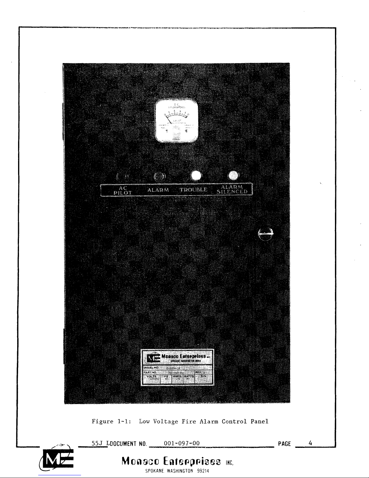
Figure
1-1:
Low
Voltage
Fire
Alarm
Control
Panel
555
LDOCUMENT
NO.
001-097-00
PAGE
4
Monaco
Ente~p~ises
INC.
SPOKANE WASHINGTON
99214
SECTION ONE
GENERAL INFORMATION
1.1 OVERVIEW
These low voltage automatic fire alarm Control Panels are local or
auxiliary units which sound local alarms and, if desired, transmit signals
to the fire headquarters through municipal Alarm boxes, McCulloh Alarm and
Trouble transmitters, polarity reversing transmitters, or Radio Alarm
System transceivers.
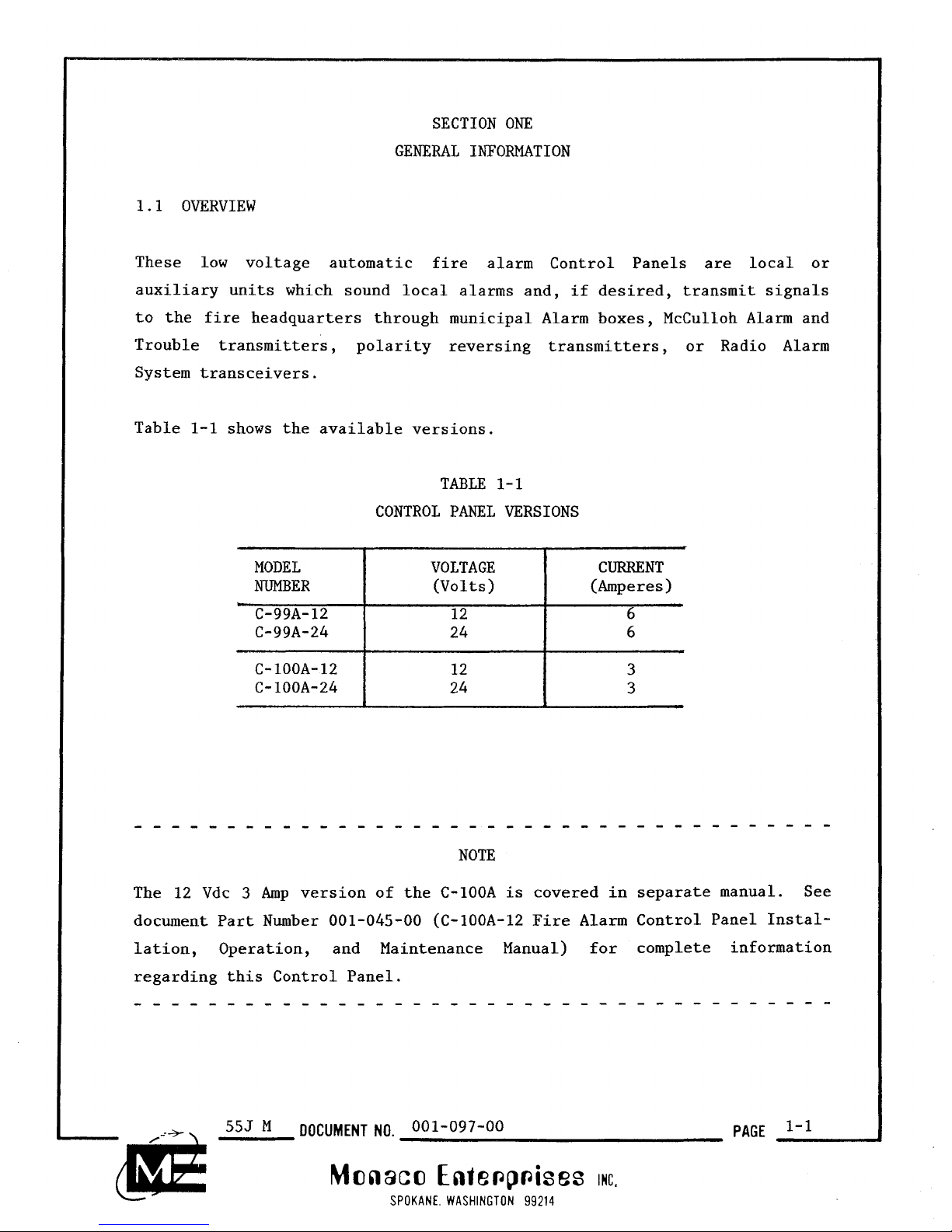
Table 1-1 shows the available versions.
TABLE 1- 1
CONTROL PANEL VERSIONS
MODEL VOLTAGE
(Volts) (Amperes)
C-99A-12
C-99A-24
......................................
NOTE
The 12 Vdc
3
Amp version of the C-100A is covered in separate manual. See
document Part Number 001-045-00 (C-100A-12 Fire Alarm Control Panel Installation, Operation, and Maintenance Manual) for complete information
regarding this Control Panel.
555
M
DOCUMENT
NO.
001-097-00
PAGE
Monaco
Entepp~ises
ING.
SPOKANE WASHINGTON
99214
The primary power input to the Control Panels is 120 VAC obtained from the
input side of the building main supply through an independent fused disconnect switch. The primary voltage is reduced and rectified to the proper
operating voltage. Terminals are also provided for connection of an emergency battery supply which is automatically connected to operate the system
in the event of a failure of the primary power.
These Control Panels are either stand-alone units or custom configured to
meet a specific application.
This manual describes the Installation, Operation, and Maintenance of the
C-99A-12, C-99A-24, and C-100A-24 low voltage automatic fire alarm Control
Panels.
1.2 FUNCTIONAL DESCRIPTION
I
All the Control Panels operate identically except for the voltage and
I
current outputs. Figure 1-2 is a simplified version of the Control Panel
models.
1.2.1 Operating Principle
Three relays operate the Control Panel circuitry. The AC monitor relay and
the Alarm relay are voltage sensitive. This means they require the full DC
voltage applied across the coil before changing their state. The Trouble
relay is current sensitive. This relay is normally energized and is
de-energized whenever supervisory current is interrupted.
555
M
DOCUMENT
NO.
001-097-00
PAGE
I'2!
Monaco Enfe~p~ises
MC.
SPOKANE. WASHINGTON
99214

NOTES
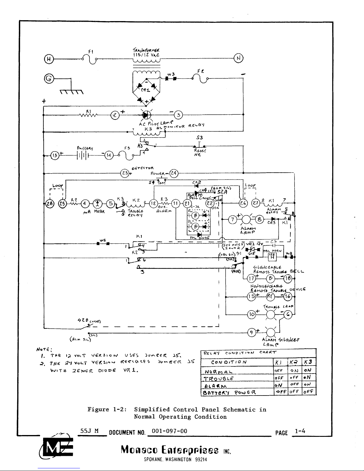
1.2.2 Normal Condition
The circuitry in Figure 1-2 shows the positive DC voltage on the left side
and the DC return on the right side. A closer study reveals several
parallel paths for potential current flow.
In the Normal condition, full potential is applied causing:
o AC pilot lamp to go ON (between terminals 2 and
3)
o AC monitor relay (K3) to energize
o Relay K3 contacts 1 and 3 to close applying normal power
to the rest of the circuit.
Detector power is applied to teminals 23 and 24. Supervisory current is
applied through to the following supervised series circuit:
o High detector loop (between terminals 28 and 25)
o Resistor R2
o Milliamp meter (between terminals
4
and
5)
o
AC
monitor relay (K3) contacts 8 and
6
o Trouble relay (K2) coil (pins 7 and 2)
o Resistor R3 (between terminals 12 and 11)
o Circuit trace (between terminals 11 and 21)
o Bell circuit end-of-line (EOL) diode
(between terminals 21 and 22)
o Alarm Silence switch (S2) contacts
A
(between terminals 22 and 26)
o Low detector loop (between terminals 26 and 27)
o Alarm relay (Kl) coil (pins 2 and 7).
The momentary Test switch S4 (between terminals 25 and 26) is used to Alarm
test the system. The momentary Reset switch S3 is used to reset the system
to Normal condition.
The standby battery is connected to terminals 13 and
14.
Fuse F3 protects
the circuitry when battery power is used.
555
M
DOCUMENT
NO.
001-097-00
PAGE
Monaco
Ente~p~ises
INC.
SPOKANE. WASHINGTON
99214
1.2.3 Trouble Condition
The series circuit containing the Trouble relay (K2) coil is the system's
supervised circuit. In the Normal condition, supervisory current is
observed by the Milliamp meter reading. The Trouble relay activates,
closing contacts
1
and 6.
An open in any portion of the series circuit causes a Trouble condition.
The following events take place:
o Supervisory Current is interrupted
o Milliamp meter reading goes to zero
o Trouble relay
(K2) de-energizes
o Trouble relay (K2) contacts 1 and
3
close
o Trouble lamp goes ON (terminals 10 and
6)
o Silenceable Trouble horn (LS1) goes ON
o Silenceable remote Trouble bell goes ON
(terminals 17 and 18)
o Nonsilenceable remote Trouble device goes ON
(terminals 15 and 16)
The silenceable Trouble horn and remote Trouble bell can be turned
OFF
by
placing the Trouble Silence switch (Sl) in the Silence position.
Correcting the Trouble condition automatically places the system in Normal
condition with one exception. The silenceable Trouble horn and remote bell
goes ON (ring back feature) indicating the Trouble Silence switch
(Sl) must
be placed in the Normal position.
1.2.4 Alarm Condition
The Control Panel goes into Alarm with the activation of any one of the
following:
o Test switch (S4)
o Heat detector
o Smoke detector
o Manual pull station.
L-
Monaco
Enie~p~ises
rc.
SPOKANE. WASHINGTON
99214
A
properly wired detector or manual pull station has its Alarm contacts (or
equivalent) closed across terminals 25 and 26 of the Control Panel.
An Alarm condition causes the following sequence of events to occur:
o Control Panel terminals 25 and 26 have a closed circuit path
o Control Panel goes into Trouble condition (see paragraph 1.2.3)
o Alarm relay
(Kl) energizes
o
Alarm relay (Kl) contacts 1 and 3 close
o Alarm relay (Kl) contacts
6
and 8 close
o Alarm lamp goes ON (between terminals 7.and
8)
o Diode CR2 conducts (between terminals 26 and 12)
o Resistor R3 or external device (auxiliary alarm) has
supply voltage applied (between terminals 12 and 11)
o Alarm bells turn ON (between terminals 22 and 21)
o Circuit conducts between terminals 21 and 11.
Silencing the Alarm bell circuit is done by placing the Alarm Silence
switch (S2) in the Silence position. The Alarm Silence lamp now goes ON
(between terminals
9
and 6). Note the auxiliary Alarm, terminals 12 and
11, cannot be silenced.
The Alarm relay (Kl) is locked ON as a result of its contacts
1
and 3
closing (terminals 26 and 27 are always shorted). This relay (Kl) coil
now has the full DC voltage applied across it.
Resetting the Control Panel can only be done by momentarily placing the
Reset switch (S3) in the Reset condition.
Be sure the alarmed detector or manual pull station is in the Normal condition or removed from the detection loop before resetting the Control Panel.
......................................
-dl@
555
M
DOCUMENT
NO.
001-097-00
PAGE
1-7
M~naco
~nie~~~ises
int.
SPOKANE. WASHINGTON
99214
The Alarm Silence lamp
will
remain
ON
indicating the Alarm Silence switch
must be placed back in the Normal condition.
1.2.5 Battery Power Condition
In the event of an
AC
power failure, the Control Panel can operate with
battery power.
A
power failure causes the following sequence of events to
occur:
o
AC
pilot lamp goes
OFF
o
AC
monitor relay (K3) de-energizes
o
AC
monitor relay (K3) contacts 1 and 4 close
o
AC
monitor relay (K3) contacts 6 and 8 open
o Battery power is applied to Control Panel
o Trouble condition occurs (see Paragraph 1.2.3)
When
AC
power is restored the Control Panel automatically restores except
for the ring back feature (due to the Trouble Silence switch (Sl) in the
Silence position). Placing this switch in Normal position turns the
audible Trouble signal
OFF.
Appendix
C
contains information on how to
calculate required battery capacity.
555
M
DOCUMENT
NO.
001-097-00
PAGE
Monaco Ente~p~ises
ac,
SPOKANE. WASHINGTON
99214
PARAMETER
Input Voltage
Input Current
Operating Voltage
Operating Current
Standard Controls
Standard Indicators
External Connections
Dimensions
Weight
C-99A-12 C-99A-24
120 Vac, 60 Hz 120 Vac, 60 Hz
1.5
A
maximum 1.5 A maximum
12 Vdc
24 Vdc
150
mA
nominal 100
mA
nominal
6
A
maximum 6 A maximum
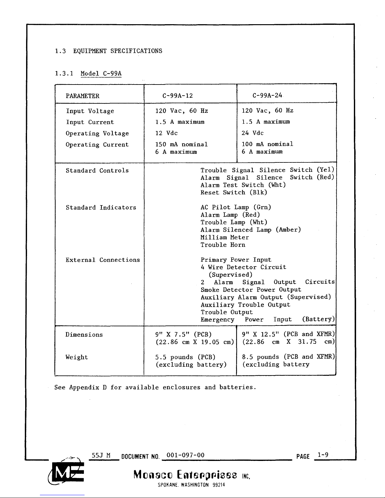
1.3 EQUIPMENT SPECIFICATIONS
1.3.1 Model C-99A
C
-
-
C
-
See Appendix D for available enclosures and batteries.
555
M
DOCUMENT NO.
001-097-00
Monaco Ente~p~ises
rc.
SPOKANE WASHINGTON
99214
Trouble Signal Silence Switch (Yel)
Alarm Signal Silence Switch (Red)
Alarm Test Switch (Wht)
Reset Switch (Blk)
AC
Pilot Lamp (Grn)
Alarm Lamp (Red)
Trouble Lamp (Wht)
Alarm Silenced Lamp
(Amber)
Milliam Meter
Trouble Horn
Primary Power Input
4 Wire Detector Circuit
(Supervised)
2 Alarm Signal Output Circuits
Smoke Detector Power Output
Auxiliary Alarm Output (Supervised)
Auxiliary Trouble Output
Trouble Output
Emergency Power Input (Battery)
9"
X
7.5" (PCB) 9" X 12.5" (PCB and XFMR)
(22.86 cm
X
19 .05 cm) (22.86 cm
X
31.75 cm)
5.5 pounds (PCB) 8.5 pounds (PCB and XFMR)
(excluding battery)
(excluding battery
PAGE
PARAMETER
Input Voltage
Input Current
Operating Voltage
Operating Current
Standard Controls
Standard Indicators
External Connections
Dimensions
Weight
120
Vac, 60 Hz
0.75
A
maximum
24 Vdc
100
mA
nominal
3
A
maximum
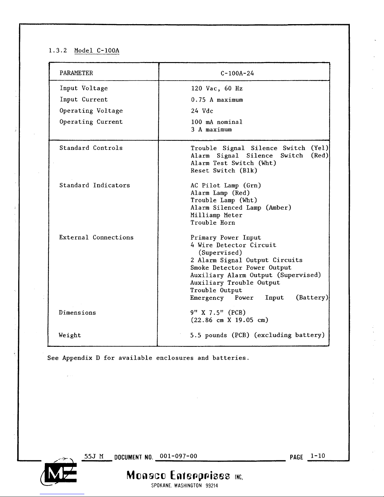
1.3.2 Model C-100A
f
-
-
L
See Appendix D for available enclosures and batteries.
555
M
DOCUMENT NO.
001-097-00
Monaco Ente~p~ises
IMC.
SPOKANE WASHINGTON
99214
Trouble Signal Silence Switch (Yel:
Alarm Signal Silence Switch (Red:
Alarm Test Switch (Wht)
Reset Switch (Blk)
AC
Pilot Lamp (Grn)
Alarm Lamp (Red)
Trouble Lamp (Wht)
Alarm Silenced Lamp (Amber)
Milliamp Meter
Trouble Horn
Primary Power Input
4 Wire Detector Circuit
(Supervised)
2 Alarm Signal Output Circuits
Smoke Detector Power Output
Auxiliary Alarm Output (Supervised)
Auxiliary Trouble Output
Trouble Output
Emergency Power Input (Battery:
9"
X
7.5" (PCB)
(22.86 cm
X
19.05 cm)
5.5
pounds (PCB) (excluding battery)
PAGE

SECTION TWO
INSTALLATION
2.1
UNPACKING
AND
INSPECTION
Your Control Panel was carefully checked and packaged at the factory and
should be ready for installation and operation when it is unpacked. If the
shipping carton shows evidence of rough handling, inspect the contents
carefully for shipping damage. If damage is found notify the carrier
immediately. Verify that all parts ordered have been received. Check the
parts against the packing list and your Purchase Order. Part lists are
provided in Section
5.
2.2
WARNINGS
2.2.1
Personnel Safeguards
The following general
safety precautions must be observed during all phases
of operation, service, and repair of this equipment. Failure to comply
with these precautions or with specific warnings elsewhere in this manual
violates safety standards of design, manufacture, and intended use of the
equipment. Monaco assumes no liability for the Customers' failure to
comply with these requirements.
A.
Proper Ground
The equipment must be connected to an electrical ground to minimize the
shock hazard.
B.
Explosive Atmosphere
Do not operate the equipment in the presence of flammable gases, fumes or
dust
.
555
N
DOCUMENT NO.
001-097-00
PAGE
2-1
Monaco Ente~p~ises
IMG.
SPOKANE WASHINGTON
99214

C. Live Circuits
Component replacement and internal adjustments must be made only by
qualified Maintenance Personnel. Do not replace components with power
connected. Under certain conditions, dangerous voltages may exist even
with the power removed. To avoid injuries, always disconnect power and
discharge circuits before touching them.
D.
Two Service Persons Required
It is recommended that another person be present when internal service or
adjustments are attempted in order to render assistance if necessary.
E.
Substitutions or Modifications
Do not install substitute parts or perform any unauthorized modifications
to the equipment before consulting with Monaco to ensure that safety
features are maintained.
2.2.2
Equipment Protection
The following general requirements must be observed during all phases of
operation, service, and repair of this equipment. Failure to comply with
these precautions or with specific warnings elsewhere in this manual may
cause considerable damage to the equipment. Monaco assumes no liability
for the Customers' failure to comply with these requirements.
A.
Power Removal
Removal of individual assemblies or their subcomponents must be done only
after power is removed from the particular equipment. This includes both
line power and battery power.
555
N
DOCUMENT
NO.
001-097-00
PAGE
2-2
Monaco Ente~p~ises
INC.
SPOKANE WASHINGTON
99214

B.
Stay within Specifications
The equipment is designed to operate within specified design parameters
such as input voltage, temperature, etc. Do not exceed the parameters
listed in the Specifications.
(See Paragraph
1.3.)
C. Authorized Personnel
Only authorized personnel are allowed to disassemble the equipment for
repair.
2.3 STANDARD CONFIGURATION
Each version of the Control Panel comes in several standard configurations.
Table 2-1 gives a detail breakdown of each configuration.
Identify the configuration purchased. An Installation, Operation, and
Maintenance Manual is included for each option in the configuration.
Contact Monaco Enterprises, Inc. to purchase additional copies of these
manua 1 s
.
Every configuration is available with the options pre-wired in an enclo-
sure. External wiring is required to complete the system, i.e. input
power, detector hook-up, and to other optional equipment.
2.4 FIELD REPLACEMENT
The low voltage automatic fire alarm Control Panels are designed to
simplify field replacement. Replaceable plug-in items are as follows:
o AC line fuse (Fl)
o DC line fuse
(F2)
o Battery power fuse
(F3)
o Alarm relay
(Kl)
o Trouble relay (K2)
o
AC monitor relay (K3).
Control Panel replacement involves removal of the electrical connections,
fasteners, and the component. See Maintenance Section for complete
details.
553
N
DOCUMENT
NO.
001-097-00
PAGE
2-3
Monaco Ente~p~ises
ac.
SPOKANE WASHINGTON
99214

TABLE
2-
1
STANDARD CONTROL
PANEL
CONFIGURATIONS
(one for
l2VDC
McCulloh-Type
Annunciator
Part Number two for
24VDC)
555
N
DOCUMENT
NO.
001-097-00
PAGE
2-4
Monaco
Ente~pises
INC.
SPOKANE WASHINGTON
99214

2.5
ENCLOSURE MOUNTING
The Control Panel and any optional accessory enclosures should be mounted
closely to each other. They may be placed at any convenient location but
preferably as close to the main building as possible. Annunciators should
be placed where the indicator lamps may be readily seen.
Before beginning any installation procedure, the PCB
Assembly(s)
MUST
BE
REMOVED
FROM
THE
ENCLOSURE.
A.
Determine where the enclosure is to be located. Use the appropriate
wall anchors, toggle bolts, lag bolts, etc., to adequately support the
weight of the enclosure. Mounting holes are provided in the back
of
the enclosure. Install any conduit necessary.
B.
After all mounting, drilling, and mechanical fitting is complete, the
enclosure must be thoroughly cleaned of all shavings and debris.
C.
Reinstall the
PCB
Assembly(s) in the enclosure using the original
hardware.
Do not use plastic anchors because they do not adequately support the
weight of the Enclosure.
See Appendix
E
for installation information on additional equipment and
accessories.
555
N
DOCUMENT
NO.
001-097-00
PAGE
2-51
Monaco
Ente~p~ises
INC.
SPOKANE WASHINGTON
99214

2.6 CUSTOM CONFIGURATION
Building monitoring requirements may change from time to time requiring
additional equipment to an existing Control Panel configuration. These new
requirements are accommodated by adding to the existing system new options.
Consult either Monaco Field Service or Customer Service for all necessary
information.
2.7 ADDITIONAL EQUIPMENT
Supervising smoke detector power leads may be done with the aid of an
end-of-line power supervision relay module. Figure 2-1 shows the supervisory scheme. The miscellaneous part Tables in Section
5
contain ordering
information for this module.
L
Single Loop Panel Functional Diagram
I
Double Loop Panel Functional Diagram
Figure 2-1: Wiring for Supervising Smoke Detector Power Leads
Refer to Appendix
D
for additional equipment which may be used in conjunc-
tion with the low voltage alarm Control Panel. See Appendix C for the
wiring diagram of a typical 24 volt installation.
555
N
DOCUMENT NO.
001-097-00
PAGE
2-6
Monaco Ente~p~ises
INC,
LT
SPOKANE. WASHINGTON
99214

SECTION TmEE
OPEMTION
This Section describes the three operating conditions (Normal, Trouble, and
Alarm). Also included are the Battery Powered Condition and Initial
Testing. Appendix
G
contains a condensed Control Operation Instruction
label included with each Control Panel.
3.1
NORMAL CONDITION
In
a
Normal condition the:
o AC pilot lamp is ON (front of enclosure)
o Milliamp meter is reading supervisory current,
8mA
nominal (front of enclosure)
o Four switches are in the "normal" (up) position
(Control Panel PCB).
Figure
3-1:
C-99A-12 PCB Assembly

3.2 TROUBLE CONDITION
In a Trouble condition the:
o Milliamp meter reading goes
to zero (front of enclosure)
o Trouble lamp goes ON (front of enclosure)
o
Silenceable Trouble horn
o Silenceable remote Trouble bell terminals 17 and
(LS1)
goes ON (Control Panel PCB)
18
have power
causing bells to ring (Control Panel PCB)
o Nonsilenceable remote Trouble device terminals 15 and 16 have
power causing device to activate (Control Panel PCB).
The Trouble horn can be turned OFF by placing the Trouble Silence switch
(Sl) in the "Silence" (down) position. Refer to Troubleshooting Section
for corrective action. Correcting the Trouble condition automatically
restores the system to normal with one exception. The ring back feature
causes the Trouble horn to sound again. This alerts the Operator to
restore the Trouble Silence switch
(Sl) to the "normal" (up) position and
silence the Trouble horn.
3.3 ALARM CONDITION
In an Alarm condition the:
o Control Panel goes into Trouble condition (see paragraph 3.2)
o Alarm lamp goes ON (front of enclosure)
o Auxiliary Alarm terminals 12 and 11 have power causing device to
activate (Control Panel PCB)
o Alarm bell terminals 22 and 21 have power causing bells to ring
(Control Panel PCB).
The Operator can silence the Alarm bells by placing the Alarm Silence
switch (SZ), located on the Control Panel PCB, in the "Silence" (down)
position. The Alarm Silence lamp now goes ON.
555
0
DOCUMENT NO.
001-097-00
PAGE
3-2
Monaco Ente~p~ises
SPOKANE. WASHINGTON
99214
INC.

The alarmed device must now he either reset to the Normal condition or
removed from the detection loop.
The Control Panel is now reset to the Normal. condition with the following
!
switches located on the
PCB.
o Momentarily place the Reset switch
(S2)
in
the "reset"
(down) position.
o Place Trouble Silence switch
(Sl)
in the "normal"
(up) position.
o Place Alarm Silence switch
(52)
in the "normal"
(up) position.
Figure
3-2:
C-99A-24 Transformer and
PCB
Assembly
555
0
DOCUMENT NO.
001-097-00
PAGE
3'3
Monaco
Ente~p~ises
IMC.
SPOKANE. WASHINGTON
99214

3.4
BATTERY
POWERED
CONDITION
Loss of primary AC power causes the Control Panel with standby batteries to
automatically go into the battery powered condition. The system's Alarm
operation is maintained. In a battery powered condition the:
o AC pilot lamp goes OFF
o Trouble condition occurs (see Paragraph 1.2.3).
Restoration of primary AC power automatically places the Control Panel in
Normal condition. The Trouble ring back feature alerts the Operator to the
changed condition.
3.5
INITIAL TEST
After the Alarm system installation is completed, wiring should be
rechecked both visually and with an ohmmeter.
Apply AC power to the system and note the AC pilot lamp on the enclosure
goes ON. Make initial voltage measurements according to Table 3-1 to
verify proper working voltages.
Figure 3-3:
C-100A-24 PCB Assembly
-
,
555
0
DOCUMENT
NO.
001-097-00
PAGE
3-4
Monaco
Ente~p~ises
m.
SPOKANE.
WASHINGTON
99214

TABLE
3-
1
CONTROL PANEL INITIAL VOLTAGES
Control Panel Nominal DC Voltages.
Terminal Block
1
C-99A-12
I
C-99A-24
I
C-
100A-24
I
Normal Condition
(+)I2
to
11
0.5 5
4
(+)21
to
22
0.5 0.5 0.5
(+)23
to
24 12 24 2 4
(+)25
to
26
10.5 22.5 22.5
(+)28
to
27
11
2 3 2 3
Trouble Condition
(+)I2
to
11
0 0 0
(+)21
to
22
0
0 0
(+)23
to
24 12 2 4 24
-L
(+)25
to
26
J-
(+)28
to
27 12 24 2 4
Alarm Condition
(+)I2
to
11
11.5 23.5
21
to
(+)22 12 2 4
(+)23
to
24
12 2 4
(+)25
to
26 0 0
(+)28
to
27
0
0
I
Battery Power Condition
(+)I2
to
11
0 0 0
(+)21
to
22
0 0 0
(+)23
to
24 12 24
2
4
(+)25
to
26 12 2 4 24
(+)28
to
27 12 2 4 24
*
Trouble condition voltage at Terminals
25
and
26
depends on where the open occurs
(0
or operating
voltage).
555
0
DOCUMENT
NO,
001-097-00
PAGE
3-5
Monaco
Ente~p~ises
ra.
SPOKANE. WASHINGTON
99214

WARNING
If this Control Panel is being connected to any central alarm system,
the authority having jurisdiction shall be notified.
No tests shall be
made without proper notification.
......................................
NOTE
Terminals 19 and 20 on all Control Panel terminal blocks are not used.
......................................
555
0
DOCUMENT
NO,
001-097-00
PAGE
3-6
Monaco
Ente~p~ises
ING,
SPOKANE WASHINGTON
99214

SECTION
FOUR
MAINTENANCE
4.1
SCHEDULED PREVENTIVE MAINTENANCE
To guarantee the entire fire alarm system is operating properly, it is
recommended a test (Alarm and Trouble condition) be performed once each
month. Tests shall be made under direct supervision of the owner or a
qualified person representing the owner and the municiple authorities
having jurisdiction.
A complete record shall be kept of all tests and operation of the system
(inspection of all equipment condition, both visual and functional,
including all batteries). After each test, the system shall be restored to
the Normal condition.
Occupants of the building shall be notified in advance as to time of
testing of sounding devices. Such tests should be held during daytime
hours.
4.2 DISASSEMBLY
AND
REASSEMBLY
Remove all
AC
input power and battery backup power from the Control Panel
enclosure before attempting to replace any components. Refer to wiring
diagrams and schematics in the Appendix for actual wiring configuration.
4.2.1
Control Panel
The Control Panel is located in the upper portion of the enclosure. Dis-
assembly requires the following:
o Remove the AC protective shield located on the top left corner of
the assembly.
o
Remove the three AC input wires
attached to terminal block (TB1).
555
P
DOCUMENT
NO.
001-097-00
PAGE
4-1
Monaco Ente~p~ises
rc,
SPOKANE WASHINGTON
99214

Only the C-99A-24 Control Panel requires these two additional steps.
o Remove the AC protective shield located on the top center of the
assembly.
o Remove the two black wires (high AC voltage) and the two green
wires (low AC voltage) attached to terminal block
(TB4).
......................................
o Carefully label and remove all internal wiring attached to
terminal blocks (TB2) and (TB3).
o Carefully label and remove all additional wiring attached to
terminal block (TB3).
o Remove the four hold down screws located near each corner of the
Control Panel.
o Carefully remove the Control Panel from the enclosure.
Assembly of a new Control Panel into the enclosure is the reversal of the
above procedure.
I
4.2.2
Transformer Assembly (C-99A-24 version only)
The transformer assembly is located at the top of the enclosure. Disas-
sembly requires the following:
o Remove the AC protective shield located on the left of the trans-
former.
o Remove the two black wires (high AC voltage) and the two green
wires (low AC voltage) attached to terminal block
(TB5).
o Remove the four hold down screws located near each corner of the
transformer assembly.
o Carefully remove the transformer assembly from the enclosure.
Assembly of a new transformer assembly into the enclosure is the reversal
of the above procedure.
555 P
DOCUMENT NO.
001-097-00
PAGE
4'2
Monaco
Enteop~ises
ac.
SPOKANE.
WASHINGTON
99214

4.2.3
Lamps
The four indicator lamps are located on the door of the enclosure. Disassembly requires the following:
o Carefully label and remove the two wires attached to the defec-
t
ive lamp.
o Using adjustable pliers crush the back of the indicator lamp.
o Carefully remove the speednut from the back of the defective
lamp.
o Carefully remove the defective lamp through front of enclosure
door.
Assembly of a new indicator lamp into the enclosure door
is
the reversal of
the above procedure with one exception. Do not crush the back of the new
indicator lamp.
[
CAUTION
I
The
AC
pilot lamp
is
a
light emitting diode (LED). Polarity must be
observed when installing or
it
will
not properly function.
4.2.4
Meter
The Milliamp meter
is
located on the door of the enclosure. Disassembly
requires the following:
o Carefully label and remove the two wires attached to the meter.
o Remove meter clamp nuts on either side of the meter clamp.
o Remove meter clamp.
o Carefully remove meter through front of enclosure door.
Assembly of a new meter into the enclosure door
is
the reversal of the
above procedure.
Monaco
Ente~p~ises
IMC.
L
fl
~-
SPOKANE. WASHINGTON
99214

4.3 TROUBLESHOOTING
Troubleshooting is presented in Tables 4-1 through 4-3. Each Table
contains one symptom with the Probable Causes and the Corrective Actions.
Determine which symptom applies to the Control Panel. Proceed to the
Appropriate Table and perform the Probable Cause and Correction Steps in
the order given.
Replace all defective parts.
Monaco provides a complete repair service program. Contact Field Service
for additional information.
TABLE 4-1
TROUBLE CONDITION
PROBABLE CAUSE
AC
Line Fuse (Fl) Open
DC
Line Fuse (F2) Open
No Supervisory Current
CORRECTIVE ACTION
Check if
CR1
diode bridge defective
Check if T1 power transformer
defective
Check for correct system wiring
Check if EOL diode is backward
Check for defective detector
Check for defective bell
Reduce peripherals
Short across the following Control
Panel terminals to check continuity (system
will
not Alarm):
o 26 to 27 (Detector Loop)
o 25 to 28 (Detector Loop)
o
4
to 5 (Meter)
o
11
to 12 (Aux. A1arm)ik
o
11
to 21 (Circuit Trace)
o 21 to 22 (Alarm Bells)*
o 22 to 26 (Alarm Sil Sw "S2"
Contacts "A")
Check if R2 (Terminals 25 and 4)
ope
nihk
Check if Alarm relay (Kl) coil open
Check if Trouble relay (K2) coil
open
Check if
AC
monitor relay (K3) coil
and contacts defective
Check if EOL diode defective
*
Do not short while panel is in Alarm condition.
J^t.
n4b
DO
not short or damage to Meter may occur.
555
P
DOCUMENT
NO.
001-097-00
PAGE
4'4
Monaco Ente~p~ises
rc.
SPOKANE WASHINGTON
99214

TABLE 4-2
CONTINUOUS
ALARM
CONDITION
I
PROBABLE CAUSE CORRECTIVE ACTION
I
Detector Loops Shorted
(Terminals 25 to 26)
Check if momentary Test switch
shorted
Check for defective loop wiring
Check for defective detectors
Check for defective manual pull
I
station
\
......................................
NOTE
The
AC
monitor relay (K3) and the Alarm relay (Kl) are the same and
can
be
interchanged if either
is
suspected of causing a problem.
......................................
Detector Loops Not Shorted
(Terminals 25 to 26)
TABLE 4-3
NO
BATTERY POWER
Replace Alarm relay (Kl)
b
PROBABLE CAUSE
1
CORRECTIVE ACTION
Battery Power Fuse (F3) open
Low Battery Voltage
Replace if battery power fuse
(F3)
open
Replace battery
(shoited)
Check battery wiring
Check if battery charger defective
Replace battery
a
%J
P
DOCUMENT
NO.
001-097-00
PAGE
4-5
1
Monaco
Ente~p~ises
INC.
SPOKANE WASHINGTON
99214


SECTION FIVE
REPLACEMENT PARTS
It is recommended that
you
have
the following spare parts on-hand to minimize
down time.
Part
numbers are
as
follows.
Part
Number
452-200-00
455-000-00
500-026-00
500-041-00
360-220-00
360-230-00
363-011-00
360-290-00
421-000-02
477-001-00
561-001-00
585-000-00
426-000-00
Description
RELAY:DPDT,12VDC,lOA CONT
RELAY:SPDT,I OPERATED,2A CONT
FUSE:FAST BLOW,1.5AMP/250V
FUSE:FAST BLOW,8AMP/32V
LAMP:INCAND,RED,l4V,lOOMA,QC
LAMP:INCAND,AMB,14V,lOOMA,QC
LED:GRN,12VDC,20MA,QC
LAMP: INCAND,WHT, I~V, 100MA,~c
ASSY,DIODE:EOL,6"LEADS
RESISTOR,P?dR:WW,50 OHM,5W,5%
XE'MR:PWR,115/230V:29V/3A,50/60
HORN:MIDI,12VDC/O.O7A,SCR
MT
BRDG RECT:VHl48,6AMP/lOOV
555
Q
DOCUMENT
NO.
001-097-00
PAGE
5'1
Monaco Ente~p~ises
at.
SPOKANE. WASHINGTON
99214

C-99A-24
(PIN 175-014-03)
PartNumber Description
452-300-00 RELAY:DPDT,24VDC,lOA CONT
455-000-00 RELAY:SPDT,I OPERATED,2A CONT
500-033-00 FUSE:FAST BLOW,3 AMP/250V
500-041-00 FUSE:FAST BLOW,8 AMP/32V
360-320-00
LAMP:INCAND,RED,28V,40MA,QC
360-330-00
LAMP:INCAND,AMB,28V,40MA,QC
363-012-00 LED:GRN,24VDC,20MA,QC
360-390-00
LAMP:INCAND,WHT,28V,40MA,QC
421-000-02 ASSY,DIODE:EOL,G" LEADS
477-016-00 RESISTOR,PWR:WW,500 OHM,5W,
426-000-00 BRDG RECT:VHl48,6AMP/lOOV
585-000-00
HORN:MIDI,12VDC/O.O5A,SCR
MT
C-100A-24
(PIN 175-014-01)
Part Number Description
452-300-00 RELAY:DPDT,24VDC,lOA CONT
455-000-00 RELAY:SPDT,I OPERATED,ZA CONT
500-123-00 FUSE:SLO BLOW,l AMP/250V
500-035-00 FUSE:FAST BLOW,4 AMP/32V
360-320-00
LAMP:INCAND,RED,28V,40MA,QC
360-330-00
LAMP:INCAND,AMB,28V,40MA,QC
363-012-00 LED:GRN,24VDC,20MA,QC
360-390-00
LAMP:1NCAND,WHT,28V,40MA9QC
421-000-02
ASSY ,DIODE
:
EOL
,6"
LEADS
477-005-00 RESISTOR,PWR:WW,400 OHM,5W,
561-001-00
XFMR:PWR,115/230V:29V/3A,50/60
585-000-00
HORN:MID1,12VDC/O.O5A,SCR
MT
426-000-00 BRDG RECT:VH148,6AMP/lOOV
-
.-+-
\
555
Q
DOCUMENT
NO.
001-097-00
PAGE
5-2
Monaco Ente~pises
rc.
SPOKANE. WASHINGTON
99214

SECTION SIX
APPENDIX
The Appendix contains the following helpful documents
.
DESCRIPTION PAGE
......................
Warranty
Schematics
C-99A-12 Control Panel PCB Assembly
......
C-99A-24 Control Panel PCB Assembly
......
C-99A-24 Transformer Assembly
.........
C-100A-24 Control Panel PCB Assembly
.....
Wiring Diagrams
............
C-99A-12 Control Panel
............
C-99A-24 Control Panel
C-100A-24 Control Panel
............
Typical Fire Alarm 24V Installation
......
Additional Equipment for Custom Configurations
...
Installation of Additional Equipment and Accessories
Battery Capacity Calculation
............
Condensed Operating Instructions
..........
55J
R
DOCUMENT
NO . 001-097-00
PAGE
6-1
Monaco
Ente~p~ises
inc
.
SPOKANE . WASHINGTON
99214

Monaco
Enteepoises
ac.
SPOKANE,
WASHINGTON
99214
LIMITED PRODUCT WARRANTY AND LIMITATION
OF
LIABILITY
Products sold by Monaco Enterprises, Inc. (hereinafter called "the Company
")
are warranted only as stated below:
Subject to the exceptions and upon the conditions specified below, the Company agrees to correct, either by repair, or
at its election by replacement, free of charge, F.O.B. Spokane, Washington, any defect of material or workmanship which
develops within
12
months from the date of delivery to the customer but in no event more than fourteen
(14)
months
after date of shipment, whichever is earlier. The buyer must notify the Company of any defect immediately after discovery, and must give satisfactory proof of defect or, upon request, return the defective item to the Company in
Spokane, Washington, at his expense for examination.
In addition to such notification and proof the following are additional exceptions and conditions:
If any expendable component or accessory incorporated in or used in connection with products manufactured by the
Company, such as batteries, visual indicators and fusing devices, or any other expendable material fails to give reasonable
service for a reasonable period of time, the Company will, at its election, replace or repair such component or accessory.
What constitutes a reasonable period of time shall be determined solely by the Company in its absolute discretion after
the Company is in possession of all the facts concerning operating conditions and other pertinent factors and after
such
component or accessory has been returned to the Company, transportation prepaid.
The Company makes no warranty concerning components or accessories not manufactured by it. However, in the event
of the failure of any component or accessory not manufactured by the Company, the Company will give reasonable assistance to the buyer in seeking an adjustment from the manufacturer of the item in question based on the manufacturer's
own warranty, if any.
The Company shall be released
From all obligations under its warranty in the event its products or parts have been subject
to accident, alteration, abuse or misuse, or which have not been operated and maintained in a normal manner.
Except as stated above, the Company makes no warranty, expressed or implied (either in fact or by operation of law),
statutory or otherwise;
all
warranties not expressly stated herein being expressly waived by the buyer.
The Company expressly disclaims any liability to its customers, dealers, distributors and representatives, and to users of
its products and to any other person or persons for special or consequential damages of any kind and from any cause
whatsoever arising out of or in any way connected with the manufacture, sale, handling, repair, maintenance or replacement of or arising out of or in any way connected with the use of said products.
Representations and warranties made by any person, including dealers, distributors and representatives of the Company,
which are inconsistent or in conflict with the terms of this warranty (including but not limited to the limitations of the
liability of the Company as set forth above), shall not be binding upon the Company unless reduced to writing and
approved by an officer of the Company.
This warranty shall be construed in accordance with and governed by the laws of the State of Washington.
This warranty gives you specific legal rights and you may also have other rights which may vary from state to state.
555
R
DOCUMENT NO.
001-097-00
PAGE
A1
Monaco
Ente~p~ises
INC.
SPOKANE WASHINGTON
99214

LOOP
AMP
I
METER
BATTERY
F3
LAST
DESIGN
CHART
RELAY
CONDITION
CHART
E=
ErJCRGlZtP
NE
=
NOT
ENIICLGIZEP
NIT
I

I
AC
PILOT
I'
I
LOOP
E=
EhlELZGIZED
N
E
:
NOT
ENEffiIZED

GRN
GRN
I
I
I
C-99A-24 Transformer Assembly Schematic
555
R
DOCUMENT
NO.
001-097-00
PAGE
B3
Monaco Ente~p~ises
rc.
SPOKANE WASHINGTON
99214

4
3
2
I
1
PROPRIETARY NOTICE
R4VlslONS
OESCRlPTlON
OATE
AP
F~RMAL
RELEASE
---
I
----
QL<
RE8
AMP
I
METEF
'Nl-C+5
0THECWtSE
TBL LAMP
0
5P%lFlED
NOTIIS"
ALM
SIL
LAMP
I,
L,NIT
5UOWN
IN
OFF
tOhlDl
TlOhr.
2
4HLDED
TCF~MINALS
ALF
IN
9IPEEVISOLY
LCOP
COMMON
3
LLL
RESISTOK5
MEASUPED
IN
OHMS.
4
ALL
CAPALITORS
FIEASVEED
I
lu
MILS2DFAfZADS.
ALM LAM
5
POLARITY
SHOWhl
OU
TERMlhl4LS
21
<
22
+.RE
FOR
AARU
MODE.
NORMAL
SLJPEKVIS
IOU
P-RITY 15
oPPOll~E
THE
ALAW NODE
POW&I~.
I
LOOP
RELAY
CONDITION
CHART
LAST
DESIGN
CHART
L-------
E=
Et4ERGIZED
NE
=
NOT
ENEtCGlZED

SUPERVISORY
NRREM
MILLInIIIIETER
0.10
MA.
IRED) ALLW
(AMBER)
ALAN
SILENCED
INSTALLATION
WIRING
DIAGRAM
CMMET
DOOR
I
M
OHM
5
WAIT
AUX.
ALARM
12
vD€
25 AMAX.
(SUPERVISED)
MODEL
C-99A-12
FIRE
ALARM
CONTROL
IRED1
ALARM SILENCE
NORMAL
SILENCE
(YELLOW)
TROUBLE
SILENCE
NORMAL
SILENCE
NORMAL
RESET
NORMAL
TEST
-
+
ALARMMODE
POLAR!TV
4-
-
SUPERVISORY
MODE
POLARITY
PAGE
C1
Monaco Ente~p~ises
MC,
SPOKANE WASHINGTON
99214
10
(SUPERVISED)
NOTE
4
NOTES:
(SUPERVISED
LBIITED
ENERGY
CIRCUIT)
Wire in accordance with NFPA Installation Standards 72A and 72B, and all applicable national, state, and local electrical codes.
Indicated circuit capacities may be exceeded provided total external current drain does not exceed 5.55 amps.
Remove resistor from terminals 11 and 12 when connecting an external device or municipal box circuit. Connect any 43 ohm 250 ma
trip coil direct. Maximum recommended supervisory current is 10 ma.
If shunt connection is used, the shunt connection is recog-
nized
as
a supplementary signaling unit
as
part of local control unit only. This type connection is not recommended as an auxiliary
control unit connection per NFPA Number 72B.
Automatic detectors, manual alarm stations and smoke detectors may be used with the C-99A but must be
U.
L. listed. The C-99A
is
also suitable for connection of waterflow alarm devices when an audible device is connected to terminals 11 and 12.
Only circuits connected to terminals 25 through 28 are limited energy arcuits.
The system
is
actuated manually or automatically through the C-99A control to sounding devices and auxiliary circuits.
The
signal
circuit is supervised noncoded type.
The C-99A may be used for local and/or auxiliary systems. When used for auxiliary systems, only rechargeable standby power system
with 60 hours capacity (NFPA 728) may be used.
U.
L. listed polarized alarm bells must be used to block the bell circuit supervisory current.
Use
IN4003 (200 volt, 1 amp) diode as end of line device on supervised alarm bell circuit.
12 VDC smoke detectors must have a minimum voltage rating of 14 VDC. End of loop detectors not having internal power supervision
must have external power supervisory module connected to the loop.
Use
Eveready 1463 battery or equal. Test battery by disconnecting AC power and placing control in alarm. Battery voltage below
10 V measured during the test indicates battery should be replaced.
For control operation instruction, refer to label
243-043-00.
Supervised power supply connections when using smoke detectors are included in I-O-M Manual, Section
11.
The
C-99A-12 is intended for the following type and senrice:
TYPE: SERVICE:
(L): Local system type. (A): Automatic fire alarm: Thermostats, smoke detectors, etc.
(A): Auxiliary system type
(M):
Manual fire alarm: ~huall~ operated boxes.
LABEL
PIN
243041.00
FBDl
REV
CMONACO
ENTERPRISES,
INC. SPOKANE.
WA
99214

INSTALLATION WIRING DIAGRAM
lW
VAC
60
HZ
3A
MAX.
(SUPERVISED)
Ill
(GREEN)
AC
PILOT
SUPERVISORY
CURRENT
MILLIMIMETER
0.10 MA.
(RED)
ALAN
(AMBER)
ALARM
SUXNCED
OXHll'E)
TROUBLE
0
AC
PRI
MODEL
C-99A-24
FIRE ALARM CONTROL
. .
(YELLOW)
TROUBLE
SILENCE
'",%?
(WHITE)
TEST
fi
&
NORMAL
&
NOPMAL
&
NORM-
4
4
SILENCE
RESET
TEST
-
+
ALARM
MODE POLARITY
CABINET
WOR
-I-
-
SUPERVISORY
MODE
POLARITY
I
SILENCE)
I,~&",L~,"X,
I$EM%zN
MAX.
CURRENT
I00
MA.
(500
NO. I4
AWG)
SUITABLE
FOR
AT
24
VDC CONNECIION
TO
REFER
10
TO
NOTE
DEVICE
INDICATED
IN
NOTE
4
NOTES:
(SUPERVISED)
(SUPERVISED
LIMITED
ENERGY
CIRCUIT1
Wire in accordance with NFPA Installation Standards 72A and 728, and all applicable national, state, and local electrical codes.
Indicated circuit capacities may be exceeded provided total external current drain does not exceed
5.55
amps.
Remove resistor from terminals
11
and 12 when connecting an external device or municipal box circuit. Connect any 43 ohm
250 ma trip coil in series with 43 ohm,
5
watt resistor and connect direct. Maximum recommended supervisory current is 10 ma.
If shunt connection is used, the shunt connection is recognized as a supplementary signalling unit as a part of local control unit
only. This type connection is not recommended as an auxiliary control unit connection per NFPA Number 72B.
Automatic detectors, manual alarm stations and smoke detectors may be used with the C-99A but must be U.L. listed. The C-99A
is also suitable for connection of waterflow alarm devices when an audible device is connected to terminals
11
and 12.
Only circuits connected to terminals 25 through 28 are limited energy circuits.
The system is actuated manually or automatically through the C-99A control to sounding devices and auxiliary circuits.
The signal circuit is supervised non-coded type.
The C-99A may be used for local
and/or auxiliary systems. When used for auxiliary systems, only rechargeable standby power
system with 60 hours capacity (NFPA 72B) may be used.
U.L. listed polarized alarm bells must be used to block the bell circuit supervisory current.
Use IN4003 (200 volt,
1
amp) diode
as
end of line device on supervised alarm bell circuit.
24 VDC smoke detectors must have a minimum voltage rating of 28 VDC. End of loop detectors not having internal power super-
vision must have external power supervisory module connected to the loop.
Use two Eveready 1463 batteries or equal connected in series. Test batteries by disconnecting AC power and placing control in
alarm. Battery voltage below 20 V measured during the test indicates batteries should be replaced.
For control operation instructions, refer to label 243-043-00.
Supervised power supply connections when using smoke detectors are included in I-0-M Manual, Section 11.
The C-99A-24 is intended for the following type and service:
TYPE: SERVICE:
(L):
Local system type. (A): Automatic fire alarm: Thermostats, smoke detectors, etc.
(A): Auxiliary system type. (M): Manual fire alarm: Manually operated boxes.
LABEL PIN 243.04240 F801 REV C MONACO ENTERPRISES INC. SPOKANE. WA 99214
555
R
DOCUMENT
NO.
001-097-00
PAGE
C2
Monaco
Ente~pises
Inc.
CPnKANF WACUINCTflhl
99714

INSTALLATION WIRING
DIAGRAM
I20
VAC
60
HZ
I A MAX
(SUPERVISED)
PRINTLO
CIRCUIT
BOAR~
TB1
I
(GREEN)
AC PILOT
SUPERVISORY
(RED)
ALARM
(WHITE)
TROUBLE
CABINET
WOR
1
MODEL
C-100A-24
FIRE
ALARM CONTROL
::
::
I
(RED1
(YELWW)
TROUBLE
HmwL
8NoMAL
Noma
%p
I
I
I
SILENCE
SILENCE
RESET
TEST
I
I
-
+
nLARM
MODE
POLARITY
I
-b
-
SUPERvlSORV
MCDE
POLARITY
I
+OOOI~MS
BATIZRY
REMOTE
TROUBLE
wA"
24V
TROUBLE
BELL
nux
3-IS AMPS
24
VDC 24VDC
ALARM
pdR
.2S(;,"TAX.
25
AMAX.
(HOT
WEN
z:42i&
TONOTE
SWERVISEDI SUPERVISED)
(SUPERVISED)
l2
(DOES
IS
USE0
.3
A
MU.
CIRCUIT
&%rq
12
SOHMS
l
2 R MAX.
ON
CONDumRS
FOR
SMOKE
I.E.
zs
m
28 & 26
m 27
(S00'NO.
IIAWCI
SUITABLE
FOR
AT
24
VDC
CONNECTION
7'0
REFER
TO
NOTE
DEVICE INDICATED
IN
10
NOTE
I
NOTES:
(SUPERVISED) (SUPERVISED
LIMITED
ENERGY
CIRCUIT)
Wire
in
accordance with NFPA Installation Standards 72A and 728, and all applicable national, state, and local electricai codes.
Indicated circuit capacities may be exceeded provided total external current drain does not exceed 2.85 amps.
Remove resistor from terminals
11
and 12 when connecting an external device or municipal box circuit. Connect any 43 ohm 250
ma trip coil in series with 43 ohm
5
watt resistor and connect direct. Maximum recommended supe~sory current is 10 ma. If shunt
connection
is
used, the shunt connection is recognized as a supplementary signaling unit as part of local control unit only. This type
connection is not recommended as an auxiliary control unit connection per NFPA Number 72B.
Automatic detectors, manual alarm stations and smoke detectors may be used with the C-100A but must be U.
L.
listed. The C-100A
is
also suitable for connection of waterflow alarm devices when an audible device is connected to terminals 11 and 12.
Only circuits co~ected to terminals 25 through 28 are limited energy circuits.
The system
is
actuated manually or automatically through the C-100A control to sounding devices and auxiliary circuits.
The signal circuit is supervised noncoded type.
?he C-100A may
be
used for local andlor auxiliary systems. When used for auxiliary systems, only rechargeable standby power system
with 60 hours capacity (NFPA 72B) may be used.
U. L. listed polarized alarm bells must be used to block the bell circuit supervisory current.
Use
IN4003 (200 volt, 1 amp) diode as end of tine device on supenriled alarm bell circuit.
24 VDC smoke detectors must have
a
minimum voltage rating of 28 VDC. End of loop detectors not having internal power super-
vision must have external power supervisory module connected to the loop.
Use two Eveready 1463 batteries or equal connected in series. Test batteries by disconnecting AC power and placing control in alarm.
Battery voltage below 20 V measured during the test indicates batteries should be replaced.
For control operation instructions. refer to label
243-045-00.
Supe~sed power supply connections when using smoke detectors are included in I-O-M Manual, Section 11.
The C-100A-24 is intended for the following type and sewice:
TYPE:
SERVICE:
(L): Local system type.
(A):
Automatic fie alarm: Thermostats, smoke detectors, etc.
(A): Auxiliary system type. (M): Manual fire alarm: Nhnually operated boxes.
LABEL
PIN
243-040-00
F7935
REV
D
MONACO
ENTERPRISES.
INC.
SPOKANE.
WA
99214

120 VAC POWER THROUGH IP 20A FUSIBLE DISCONNECT
CONNECT LINE SIDE OF DISCONNECT TO MAIN BREAKER.
I
I
CS-579-BC
I
BATTERY CHARGER
??
BATTERY CHARGER
P/N:
401
-001
-00
TO FRONT PANEL
CA42-4
ANNUNCIATOR
P/N:
710-001-00
SEE
NOT
ZONE
2
ZONE
4
(FOR GFA OR EOL ANNUNCIATDRS.
SEE RESPECnVE MANUALS)
F??f
4222
o
123456
I
I
I
TlPl
AW
I
SEE NOTE
6
I
r--'-l
AM
000000
KEMUL'
~1
u
PI PZ
n
n
NI
II~
P
*
A
I C D
lRlNC
DI
.
RT-100
SUPERMSION INTERFACE
P/N:
750-300-00
r
PNAICD
000000
12 3
4
5
6
7 8 9 10
TWPER
EOL FROM
INPUT
CONTROL PANEL
ALARM OUTPUT
K-110
ET-1 TRANSMITTER
7
2
AUXIUARY RELAY
P/N: 710-048-00
YP
P/N:
458-000-02
0
7.2
"ZZ
1234 143
8
5
1
TO AUXIUARY
CONTROL FUNCTIONS
SHUNT
C-99A/C-100A TERMINALS
I I
I
0
TB1
TB2
b b
SEE NOTE 7\ 1
2
1234
7
TM TRANSMITTER MODULE
P/N: 176-099-00
I
Lwm FOR voLrAcx
REKRSAL OR EOL RECEIVER

#
Mi-
'
/
-J
'
II
[I1
--..=..-..-
I
REVISIONS
SEE NOTE
4-
WEN AANSYlTlED ZONES ARE INOIL
MOUALLY. A
K-110
RELAY MUST
BE
USED TO PREKNT
A
TROUBLE
SCUM
Rl?l
ALL ZONE
ALARMS. ZOClE 1
lRANSYlrS ZONE
ALARM AND
PAmL
TRWBLE. ZOmS
2.
3,
&
4
TRANSWT
ALARMS ONLY.
*PPPOYED
3X.
RELAY
24
MC
a
-
I K I
(MADE NEW OWC. AOOEO
TM.
SACM. BT2-4
[
10/7/BB
]
f
&nu
DATE
ECO
;,"
:
1
2
3
4
5
CLZLI
00 00 00 00 00
lo
120 "Ac
(-
JAL CA42 ANNiJNCIATORS
REV
ZONE RT-100
w
UNUSED ZONES 00 NOT REQUIRE
TERMINATIOEI
ZONE
C
ZONE TERMINATIONS AND CONNECTIONS
ARE SAME AS ON BT2-4. EXCEPT UNUSED
ZONES MUST BE TERMINATED
WlTH 15K
OHM RESISTOR.
DESCRIPTION
ADDITIONAL BT2-
4
ZONE
CONNECTION ALTERNATE
5.)
FOR ADDITIONAL INFORMATION ON ANY PRODUCT,
CONSULT
ITS
RESPECTIVE MANUAL.
1.)
DOTTED LINES INDICATE
FOUIPMEN T.
2.)
MAY BE USEO FOR SMOKE DETECTOR POWER
PROMOED THAT TOTAL CURRENT DRAW ON
ALL ZONES
DOES NOT EXCEED THAT LISTEO
ON THE C-100A OR C-99A DATA SHEET FOR
TERMINALS 23
&
24.
THESE TERMI'IALS MAY
ALSO BE USEO FOR REMOTE ZONE ALARM MEN
6.)
TERMINALS PROWOE EASY THROUGH CONNECTIONS
FOll
F.A.C.P. DETECTION LOOP EXFANSION AND ARE ISOUTED
FROM THE RT-100 PANEL INTERFACE FVNCTION. NO
CONNECTIONS TO TERMINALS ARE REWIRED
FM INTER-
FACE OPERATION.
(79-000-00 RESISTOR ASSY.
W/tEADS. NORMALLY OPEN
COIITACTS (1.6. WATER FLOW
SHITCH,
atc.)
7.)
JUMPERS
ON
mE
M
MODULE MUST
BE
CUT
TO
SELECT
THE
DESIRED
INPUT/OUTPUT
wnom
IF
EOL
WTWT
IS USEO. AN EN0 OF LINE OEMCE WICH MATCMS
ME
SPECIFIED ON ORDER.
3.)
SUPERMSEO AUDIBLE CIRCUIT MODULES MAY BE
USEO TO EXPAND BELL CIRCUIT CAPACITY THE
INSFUCTIONS FOR DETAILS.
CONTROL PANEL
I.)
CA42/4 PCB AUXILIARY POWER/AUXILIARY ALARM
OPTION MUST BE STRAPPED FOR AUXILIARY ALARM.
mus.
SMOKE
DETECTOR
POWER
MUST BE
OBTAINED
FROM C-10OA/C-IOOA. TERMINALS 23
&
24
OR
C.4 42, TERMINALS 1
&
2.
UNLESS OTHEWlS WClFlED JOB NO.
DIMENSIONSARF IN INCHES
TOLERANCESARE: STANDARD
MONACO
ENTERBRISLS,
#1C.
FRACTIONS DECIhULS ANGLES
SPOKANE. WASHINGTON
99214
-
fl1M
.U
*
-1.
APPP~YAI~
I
~&TF
TITLE:
XXX
f
. . . . .
.-
.
. .-
-
WTERIAI
DRAWN
lO/S/as
INTERCONNECTlON DRAWING:
CHECKED
6
>&
?\
jz
ae
TYPICAL FIRE ALARM
A~MD~.F~lch III~IRR EQUIPMENT:
24
VOLT SYSTEM
I
-
L
NOTICE
1
I
FINISH OUTSTANDlNGECOlSl SIZE DRAWNGNO
REV
X-700-011-DO-D
D
.PIN
700
roll
00
K
DO NOT SCALE DRAWNG SCALE NONE
1
I
SHLtT
1
OF 1

ADDITIONAL EQUIPMENT FOR CUSTOM CONFIGURATION
Control Panels
700-010-XX C-100A Fire Alarm Control Panel, 3 AMP Capacity, 12 VDC
700-01 1-XX C-100A Fire Alarm Control Panel, 3 AMP Capacity, 24 VDC
700-01 2-XX C-99A Fire Alarm Control Panel, 6 AMP Capacity, 12 VDC
700-01 3-XX
C-99A Flre Alarm Control Panel. 6 AMP Capacity, 24 VDC
Battery Chargers
175-026-02
175-026-03
401-000-00
401.001-00
175-01 9-06
401 -002-00
401-003-00
Annunciation
7
1 0-000-00
710-001-00
7
10-002-00
7 10-003-00
7 10-004-00
7 10-040-00
7 10-046-00
Batteries
400-700-00
400-701-00
400-704-00
400-300-00
BC-112 Battery Charger, 12 VDC
BC-124 Battery Charger, 24 VDC
CU-4 Battery Charger, 12 VDC
CU.4 Battery Charger, 24
VDC
NC-579-BC-29 Nicad Battery Charger 24 VDC
CS-579 Power SupplyIBattery Charger, 12 VDC
CS-579 Power SupplyIBattery Charger, 24 VDC
CA4214-12 Four Zone Alarm and Troubie Annunciator, 12 VDC
CA4214-24 Four Zone Alarm and Trouble Annunciator, 24 VDC
CA4212-12 Two Zone Alarm and Trouble Annunciator, 12 VDC
CA4212-24 Two Zone Alarm and Trouble Annunciator, 24 VDC
CA42Rl4-24 Four Zone End of Line Resistor Annunciator, 24 VDC
CA42Rl2-24 Two Zone End of Line Resistor Annunciator, 24 VDC
GFA24 Two Zone, Class AIB Annunciator, 24 VDC
Sealed Gel-Type Battery, 12Vl5AH (See Note 1)
Sealed Gel-Type Battery,
12Vl20AH (See Note 2)
Sealed Gel-Type Battery, 12V16.5AH (See Note 1)
Nicad Battery,
24Vl7AH (7"L x 5.8" x 3.9"H)*
Transmitters and Supervisory Interface Panels
176-092-00 ET-1 McCulloh Circuit Transmitter, 12 to 24 VDCIVAC
750-200-00
RT-100 Remote Transmitter Interface Panel, Radio System, 12 VDC
750-300-00 RT-100 Remote Transmitter Interface Panel, Radio System, 24 VDC
176-099-00 TM Transmitter Module: NO, NC or Voltage Reversal Alarm and Trouble
Inputs; EOL or Voltage Reversal Output; 12 to 24
VDCIVAC
Relays
458-000-0 1 K-110-12 Auxiliary Relay, DPDT, 12 VDC
458-000-02 K-110-24 Auxiliary Relay, DPDT, 24 VDC
Accessories
Booster Panel, ACIDC, 6 AMP112 VDC
Booster Panel, ACIDC, 3 AMP112 VDC
Booster Panel, ACIDC, 3
AMP124 VDC
Supervised Audible Circuit Module, 3 AMP112 VDC*
Supervised Audible Circuit Module,
3
AMP124 VDC*
Transmitter Disconnect Switch Assembly
Lamp Test Switch Assembly, 12 volt (8 lamps per assembly)
Lamp Test Switch
~ssembly, 24 volt (8 lamps per assembly)
Pre-Signal Alarm Assembly
Height
7.75"
7.75"
7.75"
11.75"
2.5"
2.5"
8.5"
8.5"
10.5"'
6"
6
"
8.5"
8.5"
5"
5"
8.5"
5"
5"
*Items must be in a separate enclosure from the Control Panel.
-
,--+
\
55JR
DOCUMENTNO.
001-097-00
PAGE
Ill
Monaco
Ente~p~ises
INC.
SPOKANE.
WASHINGTON
99214

STEPS:
1.
Determine what components will be required for a
complete operational system.
2. Obtain height measurements for each component.
3.
To determine the size of the control panel enclosure
needed, follow the guidelines listed below:
a. Leave space at the topof the panel, 1 inch required.
b. List height of first component.
c. Space each component 0.5" apart.
d. Add 0.5 after last component listed for space
at bottom of panel.
e. Add up all component spacing required.
1
'
C-100A Fire Alarm
Control Panel
7.75"
.5'
CA42 Four Zone
Alarm
&
Trouble
Annunciator
8.5
n
2.5"
Total
.
.
.
. .
21.25"
4. Compare total with standard enclosure sizes listed below. There are five standard size control panel enclosures.
After you have determined how large your custom enclosure needs to be, select the standard enclosure size that
is closest to (larger) your requirements. When ordering a control panel, the last two digits (denoted by
XX
in custom
order list) indicate what size the enclosure will be.
-00 18" Enclosure
-01 24" Enclosure
-02 12" Enclosure
-03 36 Enclosure
-04
42"
Enclosure
If your component and space measurements total 25". the correct control panel enclosure would be 36" and the
part number would have a -03 as the last two digits (i.e., 700-010-03).
Note
1:
The 5 and 6.5 amplhour batteries are 5.9" wide, 3.7" tall, and 2.6" deep. If your system is 12 VDC you
will need one battery; if your system is 24 VDC you will need two batteries. When computing the space
required for this battery, follow the guidelines below:
Rail
Batter,
-
5.9"
-
Charwr
B
1-
12"
-
6"
4
Front View
Side View
Two batteries can fit side by side-
The battery(s) can fit in front of the charger
Note 2: The 20 amplhour battery is 6.5" wide, 6.75" tall, and 5" deep. If your system is
12
VDC you will need one
battery; if your system is 24 VDC you will need two batteries. When computing the space required for this
battery, follow the guidelines below:
Battery
Rail
Chargel
Front View
+
6--i
Side View
Batteries will
NOT
fit side-by-side.
Batteries are stacked on top
of each other under the charging
unit.
001-097-00
D2
-
/
-.+-
\
55J
DOCUMENT
NO.
PAGE
Monaco
Ente~p~ises
INC.
SPOKANE. WASHINGTON
99214

INSTALLATION OF ADDITIONAL EQUIPMENT
AND
ACCESSORIES
The information in this Appendix should be carefully read before installing
these items. This information helps insure a properly installed system.
BATTERIES: When optional wet cell batteries are used, follow instructions
packed with the batteries. A battery charger must be used when wet cell
batteries are used for emergency power. If dry cell batteries are used,
ensure that the battery cases do not come in direct contact with the
enclosure surface. The bottom of the battery enclosure or Control Panel
enclosure should be covered with rubber matting.
WIRING: All wiring shall be installed in accordance with the latest edition of the National Electric Code, the applicable National Fire Protection Association Installation standards, and local authorities having
jurisdiction.
DETECTOR CIRCUITS: Any number of automatic detectors or manual fire alarm
stations may be intalled on the detector circuits provided that the stated
wire resistance on the Installation Wiring Diagram is not exceeded. Smoke
detectors may be installed on the detector circuit only to the extent that
their total current draw does not exceed the capacity stated on the
diagram. Refer to the connection diagrams supplied with the smoke
detectors used for installation and current requirements of the detectors.
Continuity of the detector loops must be maintained when connecting
detectors. Refer to Installation Wiring Diagram for proper connection of
detector loops.
BELLS: One supervised bell circuit is provided. Total current draw of the
bells may not exceed that shown on the Installation Wiring Diagram. Wire
smaller than 1/14 AWG should not be used on bell circuits.
All bells must be Polarized to block bell circuit supervisory current. A
polarized bell has an internal diode. See Figure 6-1. This diode allows
the bell current to flow only in one direction. The usual bell wire lead
555
R
DOCUMENT
NO.
001-097-00
PAGE
El
Monaco Ente~p~ises
Inc.
SPOKANE WASHINGTON
99214

colors are Red and Black (for Positive and Negative during the Alarm mode).
Wire polarized bells so that the Alarm current (electron flow) enters the
Black lead and leaves the Red lead. Some non-standard bells may have
reversed lead colors (representing Supervisory polarity rather than Alarm
polarity).
The Control Panel reverses the voltage polarity at Terminals
21
and
22
when
an Alarm is activated, changing from the Normal supervisory mode to the
Alarm mode. In the Normal mode, the internal bell diodes block the Control
Panel bell loop supervisory current and prevent the ringing of the Alarm
bells. When the polarity of the voltage is reversed (Alarm mode), the
internal bell diodes become conducting paths allowing the Alarm bells to
ring. Figure
6-1
shows two sets of polarity markings above Terminals
21
and
22
(the bell terminals). One set represents the terminal polarity
during the Normal supervisory mode; the other represents the Alarm mode
polarity. These polarities must be observed when connecting polarized
bells.
TB3 TB3
TERMINAL
21
TERMINAL
22
-
ALARM MODE POLARITY
+
SUPERVISORY MODE POLARITY
+
-
Figure
6-1:
End-of-Line Diode Configuration
0
0
555
R
DOCUMENT
NO.
001-097-00
PAGE
E2
Monaco
Ente~p~ises
INC.
SPOKANE WASHINGTON
99214
ALARM
POLARIZED BELL
MODE
r-------
CURRENT
I
1
PATH
I
I
I
I
I
BLACK LEAD RED LEAD
I
INTERNAL
BELL DIODE
I
L
1
(TYPICAL FOR ALL BELLS)
BLACK LEAD ANODE CATHODE RED LEAD
(1
EOL DIODE
CR5
+J
SUPERVISORY MODE CURRENT PATH
(ELECTRON FLOW)

END-OF-LINE DIODE: The EOL diode is connected to allow supervisory current
to flow and to block Alarm current. The Controls Panels come with a
removeable end-of-line (EOL) diode connected to terminals 21 and 22 (see
Figure 6-1). When no external bells are connected, this diode must be
secured to these terminals to prevent a constant Trouble condition. When
external bells are connected, this diode must be removed from terminals 21
and 22. Then it must be placed at the end of the bell
loop as shown in the
Installation Wiring Diagram. The diode should be connected in parallel
with the last bell.
The polarity of the diode must be observed. The diode has a red lead and a
black lead. While connected to the Control Panel, the Black lead (anode)
is connected to Terminal 21. The Red lead (cathode) is connected to
Terminal
22. When used in the last bell box, make sure the diode's Black
wire connects to the bell loop wiring that originates at Terminal 21
(+).
Likewies, make sure the diode's Red wire connects to the bell loop wiring
that originates at Terminal 22
(-).
TROUBLE BELL: Terminals are provided for a remote Trouble bell if
required. The Trouble bell should be placed where it can be readily heard
if Trouble occurs.
AUXILIARY CIRCUIT:
If
the system is for local operation only and is not to
be connected to a municipal auxiliary box, a
5
watt,
5%
resistor shall be
connected across Terminals 11 and 12 of the Control Panel. The resistor's
value is determined by the Control Panel as follows:
0
50 ohms for the C-99A-12
4.00
ohms for the C-100A-24
500 ohms for the C-99A-24
This will maintain supervision of the auxiliary circuit.
Monaco
Ente~p~ises
at.
SPOKANE
WASHINGTON
49714

If the Control Panel is to be used to activate a "shunt trip" municipal
box, Terminals
11
and
12
should be connected to the coil of an auxiliary
relay whose contacts are used to break the shunt loop. If the Control
Panel is to be used to activate a "local energy" municipal box, the
--
tripping coil should be connected directly to Terminals
11
and
12
with an
appropriate series dropping resistor. When connecting a trip coil to
terminals
11
and
12
of the Control Panel, remove the 5 watt resistor and
connect the trip coil directly. (The total resistance across Terminals
11
and
12
must equal the resistance of the original 5 watt resistor as stated
above.
OPTIONAL
ITEMS:
Refer to individual instruction sheets and connection
diagrams for optional items which may be used in conjunction with these low
voltage fire alarm Control Panels.
555
R
DOCUMENT
NO.
001-097-00
PAGE
E4
Monaco Ente~p~ises
INC.
SPOKANE
WASHINGTON
99214

APPENDIX F
BATTERY CAPACITY CALCULATION
The backup battery power must be of sufficient capacity to operate the
system in accordance with the State and National Fire Codes.
CONVERSION TABLE
milliamp
(mA)
times 1,000 = Amp
1
microamp
(
A)
times 1,000,000 = Amp
1
CALCULATION FORMULA
Number of Time Required
Device Current (Amp)
X
Devices
X
(Hours)
=
Amp-Hours
Battery capacity calculation example:
Device (Amp)
X
DEVICES
X
(Hrs)
=
Amp-Hrs
Control Panel 0.15
Trouble Bell
-
-
Remote Trouble Connection
-
-
SmokeDetector(s) (normal) 0.005
Smoke Detector(s) *(alarm) 0.05
Alarm Bell (s) 0.125
TOTAL BATTERY CAPACITY REQUIRED
9:
Use the alarm current of 10% of the number of smoke
Detectors connected to the system.
Battery capacity requirement
will
vary according to
device power requirements and assumptions made. Each
alarm system installation is unique and requires
its
own capacity calculation to insure adequate battery
backup capacity. When Monaco's Control- Panel
is
used
in auxiliary service, only rechargeable batteries with
a capacity of 60 hours must be used.
(NFPA 72B)
DOCUMENT
NO.
PAGE
Monaco
Enteopoises
INC.
PPIIKANF WAPHINCTIIN
44714

CONDENSED OPERATING INSTRUCTIONS
A
condensed Control Operation Instruction label
is
included with each
Control Panel.
CONTROL OPERATION INSTRUCTIONS
I
IF AN ALARM OCCURS:
1.
Call the Fire Department.
2.
Evacuate area or building.
TO SILENCE THE ALARM SIGNALS BELLS, HORNS):
1.
Place 'Alarm Silence' (Red) in
LOWN
position. Note that 'Alarm
Silence' light on front panel turns on to indicate abnormal switch
position. DO NOT silence alarm until cause of system activation
is known.
2.
Silence trouble horn by placing 'Trouble Silence' switch (Yellow) in
DOWN position.
TO RESET SYSTEM AFTER A FIRE ALARM:
1.
After activating devices have been returned to normal or replaced,
press momentary (Black) 'Reset' switch to DOWN position.
--Red alarm light will go out.
--White trouble light will go out.
--Trouble horn will sound. Silence horn by returning 'Trouble
Silence' switch Yellow)
UP
to normal position.
--Return 'Alann hence7 switch (Red) UP to normal position. This
will extinguish 'Alarm Silenced' light (Amber).
TO SILENCE TROUBLE HORN:
1.
Silence trouble horn by placing 'Trouble Silence' switch (Yellow) in
DOWN position. White trouble light will remain on.
NOTE
:
Trouble signal will sound if there is a loss of AC power, or if the detector loop is cut or broken.
Upon correction of trouble condition, control panel will automatically
reset itself and trouble light will go out. The horn will sound. Silence
trouble horn by returning 'Trouble Silence' Switch (Yellow) UP to
normal position.
555
R
DOCUMENT
NO.
001-097-00
PAGE
Monaco
Ente~p~ises
rc.
SPOKANE WASHINGTON
99214

--
@
HOME OFFICE:
E.
14820
SPRAGUE AVE., SPOKANE, WA.
99216 (509) 926-6277
SPOKANE. WASHINGTON SAN ANTONIO, TEXAS PANAMA CITY, FLORIDA HONOLULU, HAWAII
WASHINGTON D.C.
TAMUNING, GUAM OKINAWA, JAPAN SEOUL, KOREA
5839
 Loading...