

Monaco C-99A, C-100A Installation, Operation, Maitenance Manual
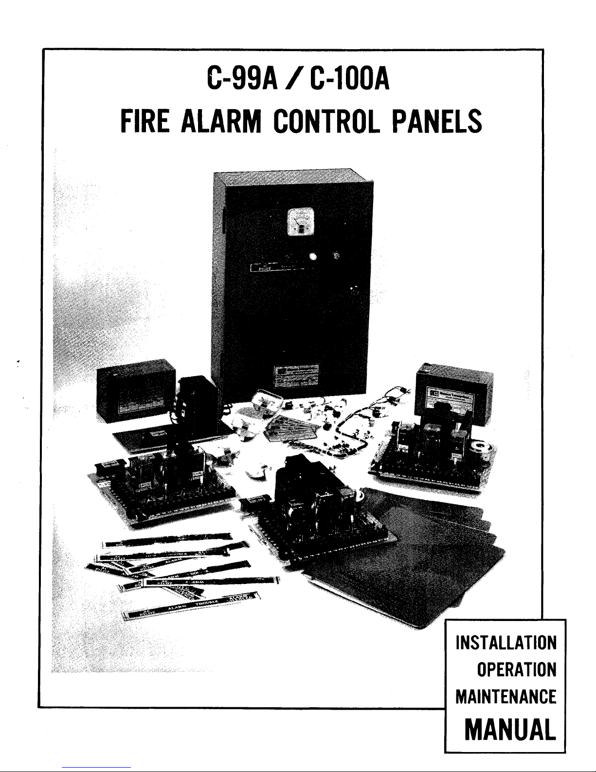
C-99A / C-100A
FIRE
ALARM CONTROL PANELS
INSTALLATION
OPERATION
MAINTENANCE
MANUAL
.
LIST
OF
EFFECTIVE
ADDENDUMS
November.
1994
The
C-99A/C-100A
Fire
Alarm
Control
Panels
I-O-M
Manual,
P/N
001-097-00,
includes
the
following addendum:
A
o
MONACO
ENTERPRISES,
INC
1994
DOCUMENT
NO.
001 -097-00
PAGE
Monaco Ente~p~ises
INC.
SPOKANE, WASHINGTON
99214
C-GQA/ C-
100A
CONTROL PANELS
INSTALLATION-OPERATION-MAINTENANCE
MANUAL
ADDENDUM
A
The
attached INTERCONNECTION
DRAWING:
?YPICAL
FIRE
AIARM
EQUIPMENT
replaces the drawing on pages C4 -C5
in
the
Appendix of
this
Manual.
MONACO
ENTERPRISES.
INC
1994
DOCUMENT
NO.
001-097-00, ADD. A
PAGE
1
of
2
Monaco Ente~p~ises
INC.
941214
CPnKANF WACUlNCTnN
P991A
C-99A/C-100A
CONTROL
PANELS
INSTALLATION
-
OPERATION - MAINTENANCE
MANUAL
Copyright, 1983
All
Rights Reserved by Monaco Enterprises, Inc., Spokane,
WA
This manual is for exclusive use by Monaco Customers and contains propri-
etary information. The manual may be loaned to subcontractors to assist in
performance of duties. Further disclosure or reproduction is expressly
prohibited unless authorized in writing by Monaco Enterprises, Inc.
These instructions are not intended to cover all details or variations in
equipment nor to provide for every possible contingency to be met in
connection with installation, operation, or maintenance. Should further
information be desired or should particular problems arise which are not
covered sufficiently for the
Customersf purposes, the matter should be
referred to Monaco Enterprises, Inc.
001-097-00
Revision
C
November, 1985

TABLE OF CONTENTS
(Continued)
SECTION
FOUR.. MAINTENANCE
4.1 SCHEDULED PREVENTIVE MAINTENANCE
..............
4.2
DISASSEMBLYANDREASSEMBLY
.................
4.2.1 ControlPanel
....................
4.2.2 Transformer Assembly (C-99A-24 version only)
....
4.2.3 Lamps
........................
4.2.4 Meter
........................
4.3 TROUBLESHOOTING
......................
PAGE
4-1
4-1
4-1
4-2
4-3
4-3
4-4
SECTION FIVE.. REPLACEMENT PARTS
.................
5-1
SECTION SIX.. APPENDIX
A..WARRCWTY
..........................
A1
B
.
SCHEMATIC DIAGRAMS
C-99A-12 Control Panel PCB Assembly
............
B1
C-99A-24 Control Panel PCB Assembly
............
B2
C-99A-24 Transformer Assembly
...............
B3
C-100A-24 Control Panel PCB Assembly
............
B4
C
.
WIRING DIAGRAMS
C-99A-12 Control Panel
...................
C1
C-99A-24 Control Panel
...................
C2
C-100A-24 Control Panel
..................
C3
Typical Fire Alarm 24V Installation
............
C4
D
.
ADDITIONAL EQUIPMENT FOR CUSTOM CONFIGURATION
.......
Dl
E
.
INSTALLATION OF ADDITIONAL EQUIPMENT
AND
ACCESSORIES
....
El
F
.
BATTERY CAPACITY CALCULATION
................
F1
G
.
CONDENSED OPERATING INSTRUCTIONS
..............
G1
LIST OF ILLUSTRATIONS
F
I
GURE
1-1
1-2
DESCRIPTION PAGE
.
Low Voltage Fire Alarm Control Panel
.........
4
Simplified Control Panel Schematic in
.............
Normal Operating Condition 1-4
Wiring for Supervising Smoke Detector Power Leads
...
2-6
.................
C-99A-12 PCB Assembly 3-1
.........
C-99A-24 Transformer and PCB Assembly
3-3
................
C-100A-24 PCB Assembly 3-4
............
End-of-Line Diode Configuration E2
LIST OF TABLES
TABLE DESCRIPTION
.
PAGE
................
1-1
Control Panel Versions
1-1
2-
1
Standard Control Panel Configurations
.........
2-4
3-1
Control Panel Initial Voltages
............
3-5
...................
4-
1
Trouble Condition 4-4
4-
2
Continuous Alarmcondition
..............
4-5
...................
4-3 No Battery Power 4-5
001-097-00
PAGE
3
555
LDOCUMENT
NO
.
Monaco
Ente~p~ises
rc
.
SPOKANE . WASHINGTON
99214
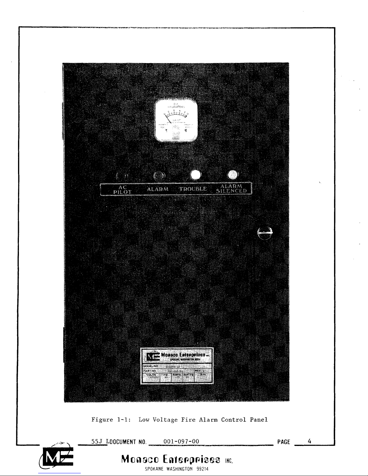
Figure
1-1:
Low
Voltage
Fire
Alarm
Control
Panel
555
LDOCUMENT
NO.
001-097-00
PAGE
4
Monaco
Ente~p~ises
INC.
SPOKANE WASHINGTON
99214
SECTION ONE
GENERAL INFORMATION
1.1 OVERVIEW
These low voltage automatic fire alarm Control Panels are local or
auxiliary units which sound local alarms and, if desired, transmit signals
to the fire headquarters through municipal Alarm boxes, McCulloh Alarm and
Trouble transmitters, polarity reversing transmitters, or Radio Alarm
System transceivers.
Table 1-1 shows the available versions.
TABLE 1- 1
CONTROL PANEL VERSIONS
MODEL VOLTAGE
(Volts) (Amperes)
C-99A-12
C-99A-24
......................................
NOTE
The 12 Vdc
3
Amp version of the C-100A is covered in separate manual. See
document Part Number 001-045-00 (C-100A-12 Fire Alarm Control Panel Installation, Operation, and Maintenance Manual) for complete information
regarding this Control Panel.
555
M
DOCUMENT
NO.
001-097-00
PAGE
Monaco
Entepp~ises
ING.
SPOKANE WASHINGTON
99214
The primary power input to the Control Panels is 120 VAC obtained from the
input side of the building main supply through an independent fused disconnect switch. The primary voltage is reduced and rectified to the proper
operating voltage. Terminals are also provided for connection of an emergency battery supply which is automatically connected to operate the system
in the event of a failure of the primary power.
These Control Panels are either stand-alone units or custom configured to
meet a specific application.
This manual describes the Installation, Operation, and Maintenance of the
C-99A-12, C-99A-24, and C-100A-24 low voltage automatic fire alarm Control
Panels.
1.2 FUNCTIONAL DESCRIPTION
I
All the Control Panels operate identically except for the voltage and
I
current outputs. Figure 1-2 is a simplified version of the Control Panel
models.
1.2.1 Operating Principle
Three relays operate the Control Panel circuitry. The AC monitor relay and
the Alarm relay are voltage sensitive. This means they require the full DC
voltage applied across the coil before changing their state. The Trouble
relay is current sensitive. This relay is normally energized and is
de-energized whenever supervisory current is interrupted.
555
M
DOCUMENT
NO.
001-097-00
PAGE
I'2!
Monaco Enfe~p~ises
MC.
SPOKANE. WASHINGTON
99214

NOTES
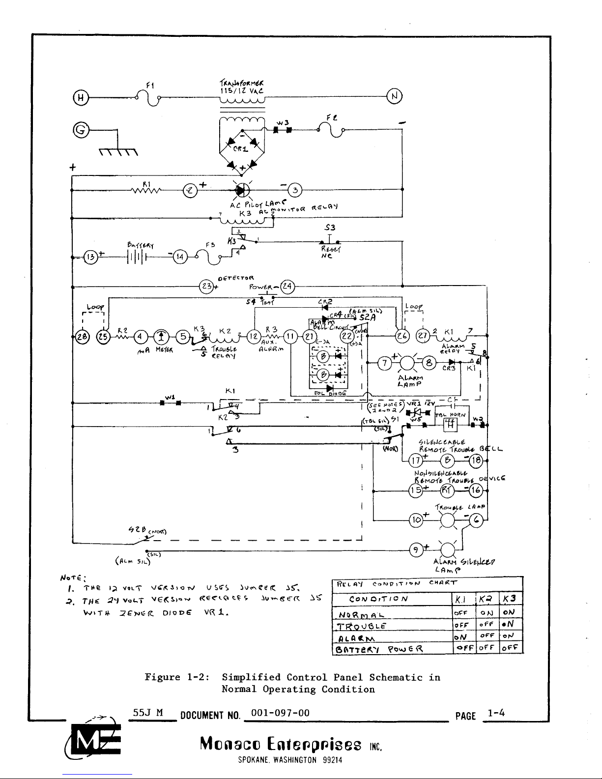
1.2.2 Normal Condition
The circuitry in Figure 1-2 shows the positive DC voltage on the left side
and the DC return on the right side. A closer study reveals several
parallel paths for potential current flow.
In the Normal condition, full potential is applied causing:
o AC pilot lamp to go ON (between terminals 2 and
3)
o AC monitor relay (K3) to energize
o Relay K3 contacts 1 and 3 to close applying normal power
to the rest of the circuit.
Detector power is applied to teminals 23 and 24. Supervisory current is
applied through to the following supervised series circuit:
o High detector loop (between terminals 28 and 25)
o Resistor R2
o Milliamp meter (between terminals
4
and
5)
o
AC
monitor relay (K3) contacts 8 and
6
o Trouble relay (K2) coil (pins 7 and 2)
o Resistor R3 (between terminals 12 and 11)
o Circuit trace (between terminals 11 and 21)
o Bell circuit end-of-line (EOL) diode
(between terminals 21 and 22)
o Alarm Silence switch (S2) contacts
A
(between terminals 22 and 26)
o Low detector loop (between terminals 26 and 27)
o Alarm relay (Kl) coil (pins 2 and 7).
The momentary Test switch S4 (between terminals 25 and 26) is used to Alarm
test the system. The momentary Reset switch S3 is used to reset the system
to Normal condition.
The standby battery is connected to terminals 13 and
14.
Fuse F3 protects
the circuitry when battery power is used.
555
M
DOCUMENT
NO.
001-097-00
PAGE
Monaco
Ente~p~ises
INC.
SPOKANE. WASHINGTON
99214
1.2.3 Trouble Condition
The series circuit containing the Trouble relay (K2) coil is the system's
supervised circuit. In the Normal condition, supervisory current is
observed by the Milliamp meter reading. The Trouble relay activates,
closing contacts
1
and 6.
An open in any portion of the series circuit causes a Trouble condition.
The following events take place:
o Supervisory Current is interrupted
o Milliamp meter reading goes to zero
o Trouble relay
(K2) de-energizes
o Trouble relay (K2) contacts 1 and
3
close
o Trouble lamp goes ON (terminals 10 and
6)
o Silenceable Trouble horn (LS1) goes ON
o Silenceable remote Trouble bell goes ON
(terminals 17 and 18)
o Nonsilenceable remote Trouble device goes ON
(terminals 15 and 16)
The silenceable Trouble horn and remote Trouble bell can be turned
OFF
by
placing the Trouble Silence switch (Sl) in the Silence position.
Correcting the Trouble condition automatically places the system in Normal
condition with one exception. The silenceable Trouble horn and remote bell
goes ON (ring back feature) indicating the Trouble Silence switch
(Sl) must
be placed in the Normal position.
1.2.4 Alarm Condition
The Control Panel goes into Alarm with the activation of any one of the
following:
o Test switch (S4)
o Heat detector
o Smoke detector
o Manual pull station.
L-
Monaco
Enie~p~ises
rc.
SPOKANE. WASHINGTON
99214
A
properly wired detector or manual pull station has its Alarm contacts (or
equivalent) closed across terminals 25 and 26 of the Control Panel.
An Alarm condition causes the following sequence of events to occur:
o Control Panel terminals 25 and 26 have a closed circuit path
o Control Panel goes into Trouble condition (see paragraph 1.2.3)
o Alarm relay
(Kl) energizes
o
Alarm relay (Kl) contacts 1 and 3 close
o Alarm relay (Kl) contacts
6
and 8 close
o Alarm lamp goes ON (between terminals 7.and
8)
o Diode CR2 conducts (between terminals 26 and 12)
o Resistor R3 or external device (auxiliary alarm) has
supply voltage applied (between terminals 12 and 11)
o Alarm bells turn ON (between terminals 22 and 21)
o Circuit conducts between terminals 21 and 11.
Silencing the Alarm bell circuit is done by placing the Alarm Silence
switch (S2) in the Silence position. The Alarm Silence lamp now goes ON
(between terminals
9
and 6). Note the auxiliary Alarm, terminals 12 and
11, cannot be silenced.
The Alarm relay (Kl) is locked ON as a result of its contacts
1
and 3
closing (terminals 26 and 27 are always shorted). This relay (Kl) coil
now has the full DC voltage applied across it.
Resetting the Control Panel can only be done by momentarily placing the
Reset switch (S3) in the Reset condition.
Be sure the alarmed detector or manual pull station is in the Normal condition or removed from the detection loop before resetting the Control Panel.
......................................
-dl@
555
M
DOCUMENT
NO.
001-097-00
PAGE
1-7
M~naco
~nie~~~ises
int.
SPOKANE. WASHINGTON
99214
The Alarm Silence lamp
will
remain
ON
indicating the Alarm Silence switch
must be placed back in the Normal condition.
1.2.5 Battery Power Condition
In the event of an
AC
power failure, the Control Panel can operate with
battery power.
A
power failure causes the following sequence of events to
occur:
o
AC
pilot lamp goes
OFF
o
AC
monitor relay (K3) de-energizes
o
AC
monitor relay (K3) contacts 1 and 4 close
o
AC
monitor relay (K3) contacts 6 and 8 open
o Battery power is applied to Control Panel
o Trouble condition occurs (see Paragraph 1.2.3)
When
AC
power is restored the Control Panel automatically restores except
for the ring back feature (due to the Trouble Silence switch (Sl) in the
Silence position). Placing this switch in Normal position turns the
audible Trouble signal
OFF.
Appendix
C
contains information on how to
calculate required battery capacity.
555
M
DOCUMENT
NO.
001-097-00
PAGE
Monaco Ente~p~ises
ac,
SPOKANE. WASHINGTON
99214
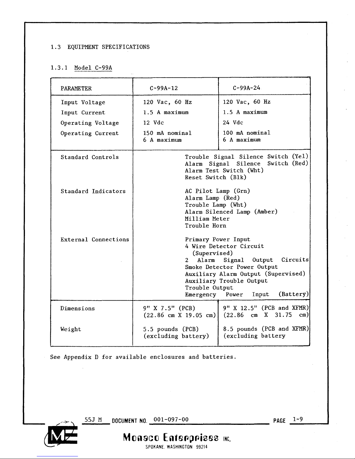
PARAMETER
Input Voltage
Input Current
Operating Voltage
Operating Current
Standard Controls
Standard Indicators
External Connections
Dimensions
Weight
C-99A-12 C-99A-24
120 Vac, 60 Hz 120 Vac, 60 Hz
1.5
A
maximum 1.5 A maximum
12 Vdc
24 Vdc
150
mA
nominal 100
mA
nominal
6
A
maximum 6 A maximum
1.3 EQUIPMENT SPECIFICATIONS
1.3.1 Model C-99A
C
-
-
C
-
See Appendix D for available enclosures and batteries.
555
M
DOCUMENT NO.
001-097-00
Monaco Ente~p~ises
rc.
SPOKANE WASHINGTON
99214
Trouble Signal Silence Switch (Yel)
Alarm Signal Silence Switch (Red)
Alarm Test Switch (Wht)
Reset Switch (Blk)
AC
Pilot Lamp (Grn)
Alarm Lamp (Red)
Trouble Lamp (Wht)
Alarm Silenced Lamp
(Amber)
Milliam Meter
Trouble Horn
Primary Power Input
4 Wire Detector Circuit
(Supervised)
2 Alarm Signal Output Circuits
Smoke Detector Power Output
Auxiliary Alarm Output (Supervised)
Auxiliary Trouble Output
Trouble Output
Emergency Power Input (Battery)
9"
X
7.5" (PCB) 9" X 12.5" (PCB and XFMR)
(22.86 cm
X
19 .05 cm) (22.86 cm
X
31.75 cm)
5.5 pounds (PCB) 8.5 pounds (PCB and XFMR)
(excluding battery)
(excluding battery
PAGE
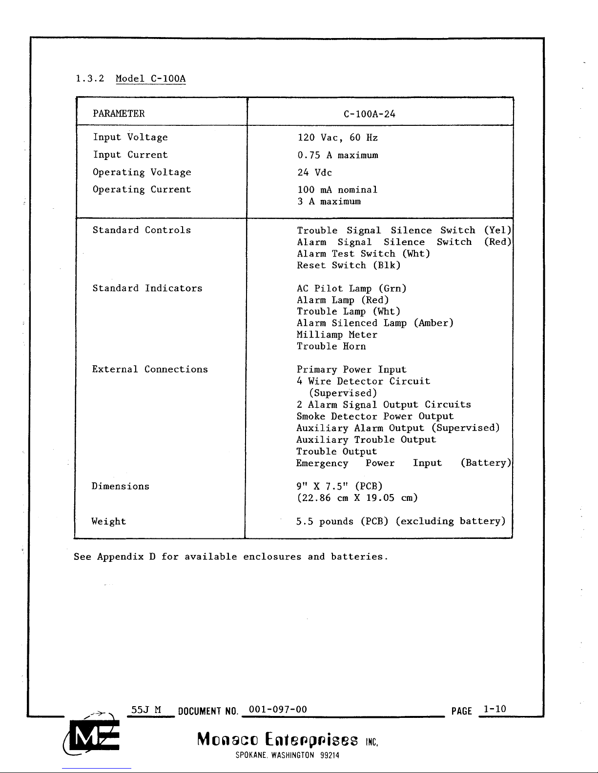
PARAMETER
Input Voltage
Input Current
Operating Voltage
Operating Current
Standard Controls
Standard Indicators
External Connections
Dimensions
Weight
120
Vac, 60 Hz
0.75
A
maximum
24 Vdc
100
mA
nominal
3
A
maximum
1.3.2 Model C-100A
f
-
-
L
See Appendix D for available enclosures and batteries.
555
M
DOCUMENT NO.
001-097-00
Monaco Ente~p~ises
IMC.
SPOKANE WASHINGTON
99214
Trouble Signal Silence Switch (Yel:
Alarm Signal Silence Switch (Red:
Alarm Test Switch (Wht)
Reset Switch (Blk)
AC
Pilot Lamp (Grn)
Alarm Lamp (Red)
Trouble Lamp (Wht)
Alarm Silenced Lamp (Amber)
Milliamp Meter
Trouble Horn
Primary Power Input
4 Wire Detector Circuit
(Supervised)
2 Alarm Signal Output Circuits
Smoke Detector Power Output
Auxiliary Alarm Output (Supervised)
Auxiliary Trouble Output
Trouble Output
Emergency Power Input (Battery:
9"
X
7.5" (PCB)
(22.86 cm
X
19.05 cm)
5.5
pounds (PCB) (excluding battery)
PAGE
 Loading...