

Monaco 134 06 05, BS EN 13240 Technical Manual
Monaco
Multi fuel stove
BS EN 13240
Model : 134 06 05
Nominal output :
5,9 kW (wood)
8,8 kW (solid mineral fuels)
Description of the appliance
Installation instructions
Operating instructions
Spare parts
Warranty certicate
Document n°1303-2
25/10/2012
Technical manual
to be saved
by the user
for future reference
Parc d’activités de la Verte Rue
Allée des Prêles
59270 BAILLEUL
Tél. : 03 28 40 32 50
Subject to modications
Monaco - 134 06 05
2 Technical manual "1303"
Package ......................................................p. 3
General characteristics .................................p. 3
Appliance description ................................... p. 3
Operating principle ......................................p. 3
Warning to the user .....................................p. 4
Location of the unit .....................................p. 4
Mounting the ue collar ...............................p. 5
Smoke exit on the top .................................p. 5
Smoke exit at rear ....................................... p. 5
Flue ............................................................ p. 5
Chimney connector ...................................... p. 6
Door closing pressure ..................................p. 6
Pre-utilisation check ....................................p. 7
Maintenance of the chimney.........................p. 7
FRANCO BELGE congratulates you on your choice.
FRANCO BELGE, guarantees the quality of its appliances and is committed to meet
its customers’ needs.
FRANCO BELGE, which can boast a 80-year experience in the industry of heating devices,
uses state-of-the-art technologies
to design and manufacture its whole range of products.
This document contains instructions on how to install your appliance and make full use of
its functions, both for your comfort and safety.
CONTENTS
Product information .................................................................................................................... p. 3
Installation instructions ............................................................................................................... p. 4
Instructions for user .................................................................................................................... p. 8
Spare parts ..................................................................................................................................p. 12
Fuel ............................................................ p. 9
Instruction for use with wood ....................... p. 9
Refuelling procedure ....................................p. 9
Operating procedure
when using solid mineral fuels .....................p. 9
De-ashing ...................................................p. 9
Maintenance of the chimney....................... p. 10
Maintenance of the stove ........................... p. 10
Safety advice ............................................ p. 10
Trouble shooting .......................................p. 11
Monaco 134 06 05
Technical manual "1303" 3
1.1. Package
• 1 package : stove.
1.2. General characteristics
* Authorised fuels under section 20 of the clean air act.
1.3 Appliance description
Multifuel stove - in conformity with BS EN 13240.
• Intermittent-burning heating appliance.
• Detachable ue spigot for rear or top chimney connection.
• Front loading door tted with large refractory glass panel.
• Adjustable primary air for controlling the burning rate.
• Large ash-pan.
1.4 Operating principle
The “ MONACO ” is designed for operation with the door
closed. Heat is mainly diffused by radiation, through the
window and body of the appliance.
Combustion occurs on the grate, with draught entry through
the top of the combustion chamber when using wood and
under the grate when using smokeless fuels
.
Reference ........................................134 06 05
Nominal heat output ............................. kW 5,9
Chimney draft required .......................... Pa 12
Hearth dimensions
- width ............................................... mm 429
- depth ............................................... mm 240
- height .............................................. mm 225
Log dimensions
- lenght maxi ........................................cm 40
Ash pan capacity ................................ litres 2,2
Net weight ............................................ kg 90
Heated Volume .................................... m3 180
PERFORMANCE WITH WOOD
Efciency (net) .......................................% 75,7
Co (13% O2) .........................................% 0,28
- Mean ue gas temperature .................. °C 317
- Flue gas mass ow ............................. g/s 4,9
PERFORMANCE WITH MINERAL SOLID FUELS (smokeless fuels)*
Nominal heat output ............................. kW 8,8
Efciency (net) ........................................% 70,6
Co (13% O2) ..........................................% 0,15
- Mean ue gas temperature ................... °C 374
- Flue gas mass ow ............................. g/s 5,8
1. Product information
This appliance is meant to burn wood safely
WARNING
Incorrectly installed, this appliance can be dangerous and possibly cause serious accidents.
We recommend that you engage the services of a professional engineer for its installation
and the regular maintenance requirements
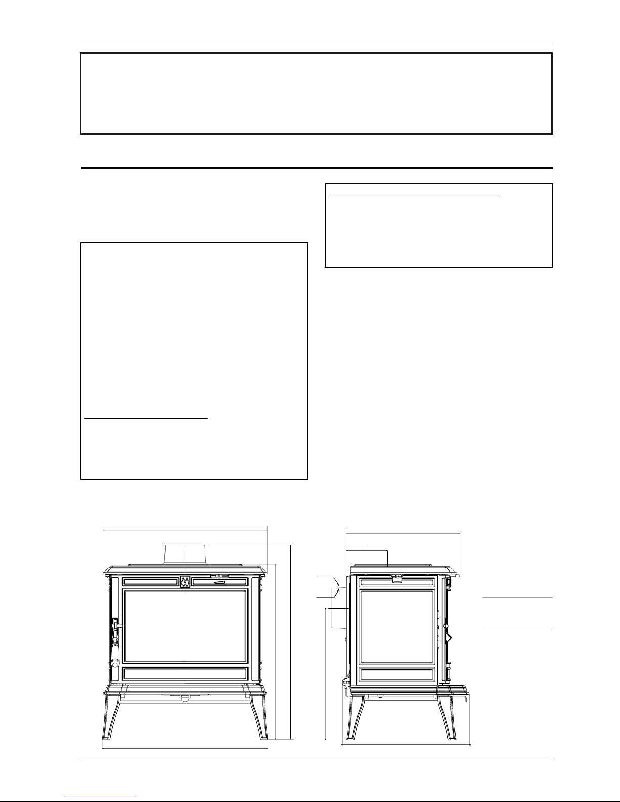
Figure 1
Dimensions in mm
561
599
654
566
433
388
141
449
Ø139
Ø125
Monaco - 134 06 05
4 Technical manual "1303"
2.1 Warning to the user
All the local and national regulations, and
in particular those relating to national and
European standards, must be observed when
installing the appliance.
An incorrectly installed heating appliance can
cause serious accidents (chimney res, burning of
plastic insulation materials, in partition walls, etc.).
This stove is exempted by DEFRA for burning wood
logs in UK Smoke Control Areas (SCA). DEFRA
exemption is dependent upon the appliance being
tted with a mechanical stop to prevent closure of the
secondary air control beyond the 25% open position.
You should check that this stop mechanism is tted
before installation of the stove and certainly before
using the stove in a SCA to burn wood logs. If the stop
mechanism is tted then the minimum chimney ue
diameter can be 125 mm but if the stop mechanism
is not tted then the stove is not exempted and
the minimum chimney ue diameter is 150 mm in
accordance with Approved Document J of the building
regulations.
The insulation of both the appliance and the
exhaust gas pipe has to be reinforced and done
according to the Standards and the Building Regulations
for safety reasons. The installation must be carried
out according to the Standards and the Building
Regulations. Failure to respect the manufacturer’s
instructions will invalidate the warranty.
The manufacturer’s responsibility shall be limited to
the supply of the appliance.
2.2 Location of the unit
Ventilation : For satisfactory appliance operation
with a natural draught, check that sufcient air
for combustion is available in the room. In houses
equipped with one VMC (controlled mechanical
ventilation), this one aspire and renew the ambient
air ; in this case, the residence is under slight low
pressure and a non-sealable external air intake must
be installed in addition to the chimney itself, at least
50cm² in section.
Position of the unit : For new installations, select
a central position within the house, to provide a
good heat distribution around the building. The heat
distribution towards the other rooms will be made
through the communicating doors. These rooms must
be at low pressure or tted with non-adjustable
air registers, placed so that they cannot be
obstructed, to encourage circulation of the hot air.
Floor and walls : make sure there are not combustible
or covered with non combustible material. Otherwise
it must be necessary to install a non combustible
protection.
2. Installation instructions
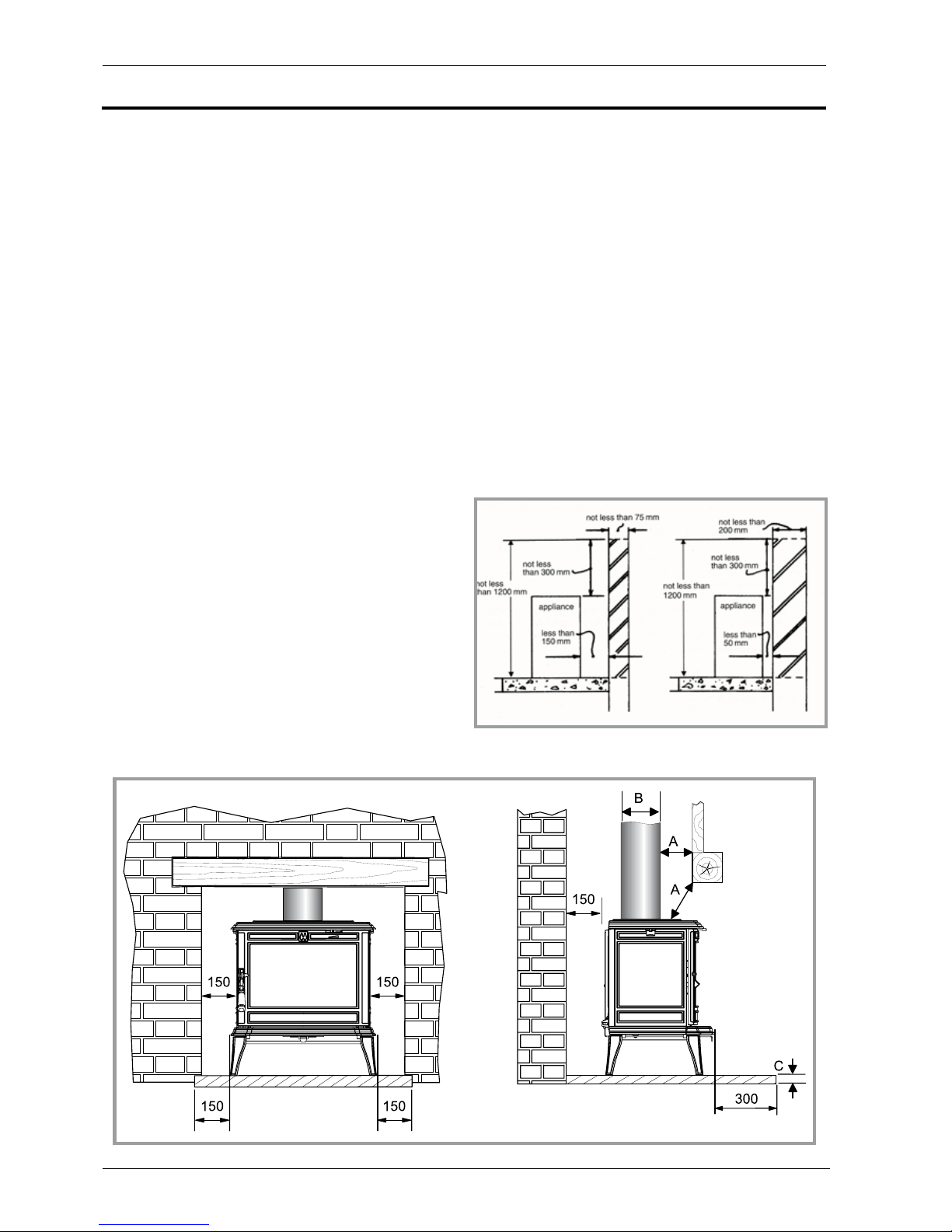
Figure 3 - Minimum clearances
Figure 2 - Smoke exit on the top
Monaco 134 06 05
Technical manual "1303" 5
There must be a clearance of at least 150 mm at each
side (back and sides) of the appliance in accordance
with the below recommandations from a non
combustible wall. This distance must be extended to
a minimum clearance of 650 mm side and 700 back
from any combustible material.
If any part of the back or sides of the appliance lies
within 150 mm horizontally of the wall, than the wall
should be of solid non-combustible construction at
least 50 mm thick from level to a level of 200 mm
above the top of the appliance and 1200 mm above
the hearth.
Il however, any part or sides of the appliance lies
within 50 mm of the wall, then the wall should be of
solid non-combustible construction at least 200 mm
thick from oor level to a level of 300 mm above the
top of the appliance and 1200 mm above the hearth.
Where the hearth itself in at least 150 mm from an
adjacent wall.
There is no requirement for protection of the wall. It
should be noted that these thicknesses of solid noncombustible material can be substituted by thinner
material if the same overall level of protection can be
achieved.
When using a single wall ue pipe, there must be
a clearance (A) of at least three times its diameter
(B) from any combustible materials. If the appliance
has to be located in an opening, this distance must
be extended to a minimum clearance (A) of 450 mm
from the pipe or the stove body to any combustible
materials.
Hearth : The appliance must stand on a reproof
hearth. It is possible to provide a hearth made of
non combusible board/sheet material or tiles at least
12 mm thick (C). Constructional hearths should be
constructed of solid non combustible material at least
125 mm thick (including the thickness of any non
combustible oor under the hearth).The hearth must
protrude at least 300 mm in front of the stove and
150 mm each side. Hearths are provided to prevent
combustion appliances setting re to the building
fabric and furnishings and to limit the risk of people
being accidentally burnt.
Therefore, they should be separated from adjacent
combustible materials and should be satisfactorily
delineated from surrounding oor nishes (carpets
etc.) as follows.
Combustible material should not be placed under a
constructional hearth for a solid fuel appliance within
a vertical distance of 250 mm from the upper surface
of the hearth, unless there is an airspace of at least
50 mm between the combustible material and the
underside of the hearth.
Where a superimposed hearth has been placed onto a
constructional hearth, combustible material placed on
or besid the constructional hearth should not extend
under the superimposed hearth by more than 25 mm
or closer to the appliance than 150 mm.
Ensure that the hear th (super imposed or
constructional) is suitably delineated to discourage
combustible oor nishes from being laid too close to
the appliance, by marking the edges or providing a
change of level.
Position the appliance on the hearth such that
combustible marerial cannot be laid closer to the base
of the appliance than :
(a) At the front, 300 mm if the appliance is an open
re or stove which an, when opened , be operated as
an open re, or 225 mm in any other case ;
(b) At the back and sides, 150 mm or in accordance
with the recommendations below which relate to
distance from hearth to walls. Please refer to section J
of the Building regulations.
When using a single wall ue pipe, there must be a
clearance (A) of at least 450 mm from any combustible
materials (timber mantel, girder).
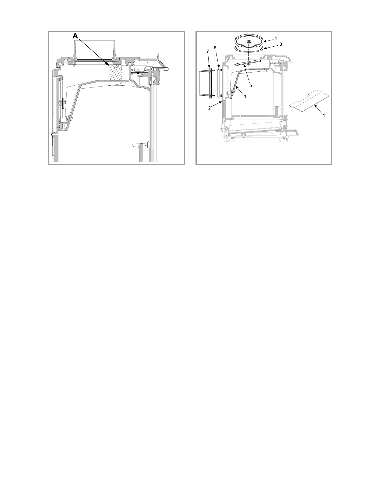
Figure 4 - Smoke exit on the top
1 - Flue bafe
2 - Back panel
3 - Gasket
4 - Blanking plate
5 - Clamp
6 - Gasket
7 - Flue collar
Figure 5 - Smoke exit at rear
 Loading...