

Momentum Sales & Marketing T7 User Manual

MOMENTUM T7 TREADMI LL
USER MANUAL

2 MOME NTUM T7 TREADMILL
For future service or related question s:
Please staple your receipt and/or write in the name and phone number of t he retail store where you purchas ed y our treadmill.
Nam e: ______________________________ Phone Number: ___________________ Rec eipt: ______________________
Precautions:
WARNING: To reduce the risk of burns , fire, elec t ric shock, or injury to persons, read the f ollowing import ant prec aut ions and
information before operat ing the t readmill. I t is the responsibility of t he owner to ensure t hat all us ers of t his t readm ill are
adequately informed of all warnings and prec aut ions.
PRECAUTIONS
• Us e the t readmill only as described in t his m anual.
• Place on a level s urface, with 6 feet (2 m ) of clearance behind it . D o not plac e the treadm ill on any surface t hat blocks air
openings. To prot ect the f loor or carpet f rom damage, place a mat under t he treadm ill.
• When c hoosing a loc ation for the t readm ill be s ure the location and pos it ion permit acc ess to a plug.
• Keep the treadmill indoors, away f rom m oisture and dust. D o not put the t readm ill in a garage or covered patio, or near
water.
• Do not operate the t readmill where aeros ol products are used or where oxy gen is being adm inistered.
• Keep children under the age of 12 and pet s away f rom the treadmill at all t imes.
• The treadmill should not be used by persons weighing more than 400lbs.
• Nev er allow m ore than one person on the treadmill at a t im e.
• Wear appropriat e exercis e clot hing when using the treadmill. Do not wear loose clothing that could bec ome caught in t he
treadm ill. Athletic support clothes are rec ommended for bot h men and women. Always wear athletic shoes. Nev er use the
treadm ill with bare f eet, wearing only st ocki ngs, or in s andals.
• When c onnecting the power c ord, plug the power cord into a grounded c ircuit. No other applianc e should be on t he same
circuit.
• Alway s straddle t he belt and allow it t o start moving bef ore stepping onto the belt.
• Alway s examine y our treadm ill bef ore using to ensure all parts are in working order.
• Allow the belt to f ully st op before dismount ing.
• Nev er insert any object or body parts into any opening.
• Follow the saf ety information in regards to plugging in y our treadmill.
• Keep the power c ord away f rom t he incline wheels and do not run the power c ord underneath your treadmill. D o not
operate t he treadm ill wit h a dam aged or fray ed power cord.
• Always unplug the treadmill before cleaning and/or serv ic ing. Serv ice to y our treadmill should only be performed by an
authorized serv ice repres entativ e, unless authorized and/ or instructed by t he manuf acturer. Failure to f ollow these
inst ructions will void t he treadm ill warranty.
• N ev er leave t he treadm ill unattended while it is running.
www.greenmasterfitness.com.tw
3
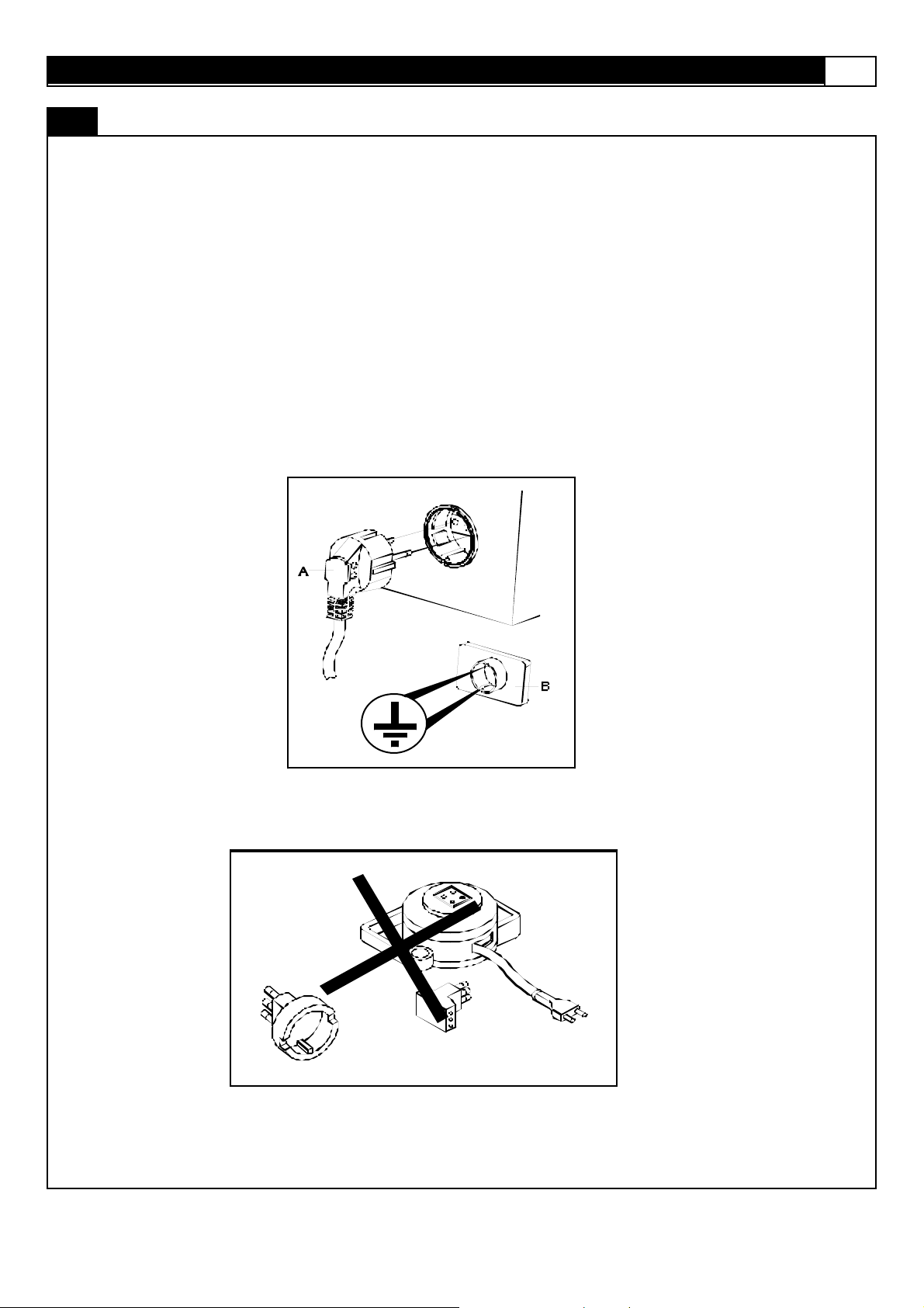
Power Requirements :
IMPROPER CONNECTION OF THE EQUI PMENT GROUNDING CONNEC TOR CAN RESULT IN A R I SK OF AN ELECTRI C
SHOC K. C H ECK WI TH A QUALIFI ED ELECTRICI AN OR SERVICE MAN IF YOU ARE I N DOUBT AS TO W H ETHER THE
PRODUCT IS PROPERLY GROUNDED. DO NOT MODIFY THE PLUG PROVIDED WITH THE PRODUCT, IF IT WILL NOT FIT
THE OUTLET; HAVE A PR OPER OUTLET INSTALLED BY A QUALIFI ED ELECTRICIAN.
This treadm ill can be s erious ly dam aged by sudden voltage changes in your hom e’s elect rical power. Voltage spik es, surges and
noise int erference can res ult from weather c ondit ions or f rom other appliances being t urned on or of f . To reduce the possibility of
treadm ill damage, alway s us e a s urge protector (not included) with y our treadmill.
This treadm ill must be grounded t o reduce t he risk of elec t rical shock. Grounding prov ides a path of least resistance for electric
current , should the t readmill malf unction. This treadm ill comes wit h an electric al cord hav ing an equipm ent -grounding conducto r
and a grounding plug. Alway s plug t he power c ord into a s urge protect or, and plug the surge protector int o an appropriate outlet
that is properly inst alled and grounded in accordance with all loc al codes and ordinanc es.
This product is for us e on a nominal 230-volt circuit, and has a grounding plug t hat looks like the plug illust rated in the drawing
below.
POWER REQ UIRE MENTS

4 MOME NTUM T7 TREADMILL
Open the boxes:
Y ou are now ready to open t he boxes of y our new equipm ent. Make sure t o invent ory all of the parts that are inc luded in t he boxes.
Chec k the Cont ents Checklist and Hardware C om parison Chart f or a full count of t he number of parts included for this product to be
ass em bled properly.
Ga t he r yo ur to ols :
Before start ing the assem bly of your unit, make sure t hat y ou have gathered all the necessary tools y ou may require to as s emble
the unit properly . Having all of t he necess ary equipm ent at hand will s av e time and mak e the ass embly quick and hassle-f ree.
Cl ear your work area:
Make sure that you hav e cleared away a large enough space to properly as s emble the unit. Mak e sure the space is free f rom
anyt hing that may caus e injury during assembly. Aft er the unit is f ully assembled, mak e sure t here is a c omfort able amount of free
area around the unit f or unobstructed operation.
Invite a friend:
Some of the ass embly steps may require heav y lif t ing. I t is recom m ended that you obtain the as s istance of another pers on when
ass em bling this product.
User Weight Limitation:
Please not e that there is a weight limitation for this product . If you weig h more than 400lbs. it i s not recommended th at you
use this product. Ser iou s injury may o ccur if the user’s weight exceed s the li mit sh o wn her e. This product is not intended
to s upport us ers whose weight exceeds this limit.
PREASSEMBLY
www.greenmasterfitness.com.tw
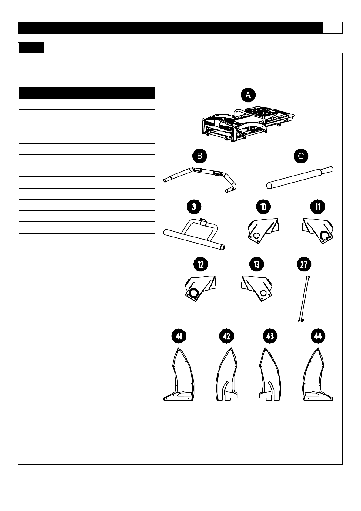
C a rt on co nt e nt s :
For y our conv enienc e, we hav e identif ied the contents of the shipping carton. Pleas e check to mak e sure you have all of the
com ponents before as s embly. This chart is prov ided to help y ou identify the com ponents used in the as s embly of this produc t.
No. Description Qty.
CO NTENTS CHECKLIST
5
A
Main Frame Assembly
B Front Handlebar Assembly 1
C Handlebar Assembly 2
3 Cons ole Support Tube 1
10 Handlebar R ear End Cap - Lef t # 1 1
11 Handlebar R ear End Cap - Lef t # 2 1
12 Handlebar R ear End Cap - Right # 1 1
13 Handlebar R ear End Cap - Right # 2 1
27 Upright Support Tube 2
41 Upright Plastic Shroud Left #1 1
42 Upright Plastic Shroud Left #2 1
43 Upright Plastic Shroud R i ght #2 1
44 Upright Plastic Shroud R i ght #1 1
1
6 MOME NTUM T7 TREADMILL
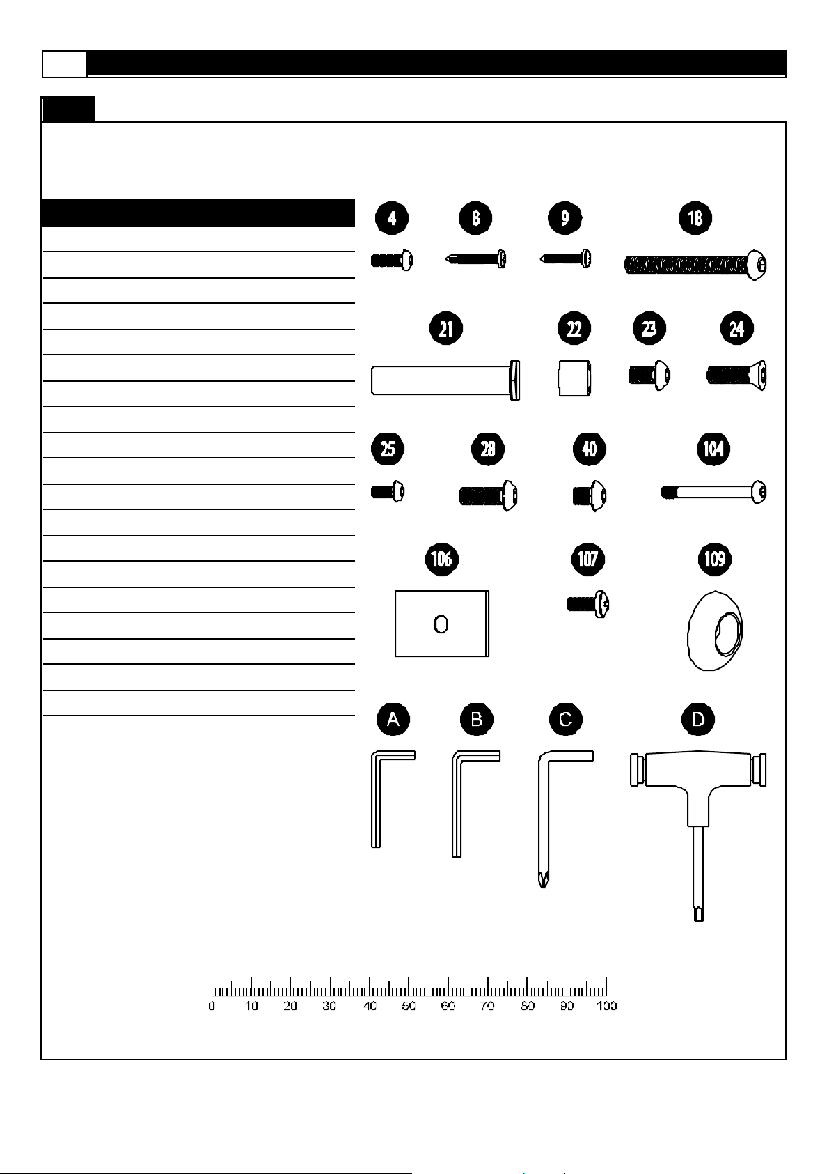
Hardware chart:
For y our conv enienc e, we hav e identif ied the hardware used in the ass embly of this product. This chart is prov ided to help you
identify t hose items that may be unf amiliar to y ou.
No. Description Qty.
H ARDWA RE COMPARISON CHART
4
M6 x 20mm Allen Head Bolt
8 #8 x 19mm Screw 20
9 #8 x 25mm Screw 8
18 M8 x 95mm Screw 2
21 1/2" x 68mm Bolt 2
22 Plastic Spacer 4
23 M8 x 25mm Allen Head Bolt 2
24 M10 x 20mm Allen Head Bolt 4
25 M8 x 20mm Allen Head Bolt 2
28 M8 x 15mm Allen Head Bolt 6
40 M8 x 10mm Allen Head Bolt 4
104 Console Screw 2
106 Upright Cover 2
107 M6 x 15mm Screw 2
109 Metal Cap 2
A 4mm Wrench 1
2
B 5mm Wrench 1
C Phillips H ead Wrench 1
D 6mm Wrench 1
MILLIMETERS

www.greenmasterfitness.com.tw
7
No. Description Qty. Or d er No. No. Description Qty. Or d er No.
1 Com put er 1 T7 - 001 35 Cus hion 4 T7 - 035
2 Key pad 1 T7 - 002 36 M6 x 13mm Was her 2 T7 - 036
3 Cons ole Support Tube 1 T7 - 003 37 #8 x 15mm Screw 38 T7 - 037
4 M6 x 20mm Allen Head Bolt 2 T7 - 004 38 Cons ole Housing - Bot t om 1 T7 - 038
5 C ons ole Support Tube 1 T7 - 005 39 D ec k Fixing Tube 1 T7 - 039
6 N/ A 40 M8 x 10mm Allen Head Bolt 4 T7 - 040
7 Plast ic Fixing Ins ert 8 T7 - 007 41 U pright Plastic Shroud Left #1 1 T7 - 041
8 #8 x 19mm Screw 24 T7 - 008 42 Upright Plastic Shroud Left #2 1 T7 - 042
9 #8 x 25mm Screw 8 T7 - 009 43 U pright Plastic Shroud R ight #2 1 T7 - 043
10 H andlebar R ear End Cap - Lef t # 1 1 T7 - 010 44 Upright Plastic Shroud R i ght #1 1 T7 - 044
11 H andlebar R ear End Cap - Lef t # 2 1 T7 - 011 45 Side Cov er - Left 1 T7 - 045
12
13
14 H andlebar Grip 2 T7 - 014 48 M5 x 10mm Screw 2 T7 - 048
PARTS LIST
Handlebar R ear End Cap - Right #
1
Handlebar R ear End Cap - Right #
2
1 T7 - 012 46 Side Cov er - Right 1 T7 - 046
1 T7 - 013 47 Power Swit c h Set 1 T7 - 047
15 H andlebar 2 T7 - 015 49 Motor Hood 1 T7 - 049
16 H and Puls e Sensor 2 T7 - 016 50 Top Maintenance C over 1 T7 - 050
17 C ons ole Housing - Upper 1 T7 - 017 51 #8 x 50mm Screw 2 T7 - 051
18 M8 x 95mm Screw 2 T7 - 018 52 Aluminum Side Rail 2 T7 - 052
19 U pright - Left 1 T7 - 019 53 Running Belt 1 T7 - 053
20 U pright - Right 1 T7 - 020 54 Running D eck Rear C over 1 T7 - 054
21 1/ 2" x 68mm Bolt 2 T7 - 021 55 Rear F oot Platform 1 T7 - 055
22 Plas t ic Spacer 4 T7 - 022 56 Rubber Spac er - Left 1 T7 - 056
23 M8 x 25mm Allen Head Bolt 2 T7 - 023 57 Rubber Spac er - R ight 1 T7 - 057
24 M10 x 20mm Allen Head Bolt 4 T7 - 024 58 Running D eck 1 T7 - 058
25 M8 x 20mm Allen Head Bolt 2 T7 - 025 59 Dec k Rubber Cushion 10 T7 - 059
26 Adjus t able Cy linder 2 T7 - 026 60 M10 x 35mm Bolt 1 T7 - 060
27 U pright Support Tube 2 T7 - 027 61 M5 x 15mm Sc rew 2 T7 - 061
28 M8 x 15mm Allen Head Bolt 16 T7 - 028 62 Clip 2 T7 - 062
29 M6 x 55mm Allen Head Bolt 2 T7 - 029 63 Elevation Motor 1 T7 - 063
30 M14 x 113mm Bolt 2 T7 - 030 64 M10 Ny lon Nut 2 T7 - 064
31 Bus hing 4 T7 - 031 65 Tension Wheel 1 T7 - 065
32 St abilizer 2 T7 - 032 66 Front Vent Cover 1 T7 - 066
33 Bas e F rame 1 T7 - 033 67 Rear Vent Cover 1 T7 - 067
34 R unning D eck Fix ed Tube Sleeve 2 T7 - 034 68 Logo Light Bracket 1 T7 - 068

8 MOME NTUM T7 TREADMILL
No. Description Qty. Or d er No. No. Description Qty. Or d er No.
69 D riv ing Motor 1 T7 - 069 103 #8 x 35mm Screw 4 T7 - 103
70 R oller C arbon Brush 1 T7 - 070 104 Console Screw 2 T7 - 104
71 Motor H older 1 T7 - 071 105 Handlebar F ixing Plat e 2 T7 - 105
72 Motor H older Adjustment 1 T7 - 072 106 Upright Cov er 2 T7 - 106
73 M10 x 136mm Bolt 1 T7 - 073 107 M6 x 15mm Screw 2 T7 - 107
74 M10 x 63mm Bolt 1 T7 - 074 108 Front Handle bar 1 T7 - 108
75 Motor D riv e Belt 1 T7 - 075 109 Met al C ap 3 T7 - 109
76 Tension W heel Bracket 1 T7 - 076 110 M8 x 45mm Bolt 12 T7 - 110
77 Transfer Board 1 T7 - 077 111 Emergency St op 1 T7 - 111
78 F ront Roller 1 T7 - 078 112 Hand Puls e Sensor W ire - Upper 2 T7 - 112
79 F ront Roller Shaf t 1 T7 - 079 113 Side Rail Guide Light Board 1 T7 - 113
80 D ec k Frame 1 T7 - 080 114 N/ A
PARTS LIST
81 Micro Switc h 1 T7 - 081 115 N/ A
82 M8 x 70mm Bolt 3 T7 - 082 116 Handle Bar Plas t ic Bushing 2 T7 - 116
83 8 x 16 x T2.0 Washer 13 T7 - 083 117 Motor C ont rol Board 1 T7 - 117
84 Motor H ood Side Cov er - Left 1 T7 - 084 118 Motor Cont rol Board Fan 1 T7 - 118
85 Motor H ood Side Cov er - Right 1 T7 - 085 119 Main Trans f ormer 1 T7 - 119
86 F ram e Side Cov er - Lef t 1 T7 - 086 120 N/ A
87 F ram e Side Cov er - Right 1 T7 - 087 121 N/ A
88 Plas t ic Clamp - Top 2 T7 - 088 122 N/A
89 Plas t ic Clamp - Bottom 2 T7 - 089 123 Motor Cont rol Board Cov er 1 T7 - 123
90 Brac k et 2 T7 - 090 124 Motor Cont rol Board Radiat or 1 T7 - 124
91 M8 x 25mm Screw 4 T7 - 091 125 Rear Frame 1 T7 - 125
92 R ear R oller 1 T7 - 092 126 Foot Platf orm Support F ram e 1 T7 - 126
93 R ear R oller Shaft 1 T7 - 093 127 Deck Frame Side C over - Lef t #2 1 T7 - 127
94 M8 x 43mm Bolt 2 T7 - 094 128 Deck Frame Side C over - Right #2 1 T7 - 128
95 M8 Ny lon Nut 12 T7 - 095 129 10 x 16 Washer 1 T7 - 129
96 D ec k Wheel 2 T7 - 096 130 Side Rail Guide Light 2 T7 - 130
1
97 Rubber Dot
98 D ec k Wheel Brack et 2 T7 - 098
Elevation Support Tube Side C over
99
- Lef t
Elevation Support Tube Side
100
Cov er - Right
101 Elevat ion Support Tube 1 T7 - 101
T7 - 097
SET
1 T7 - 099
1 T7 - 100
102 Motor Belly Pan 1 T7 - 102
www.greenmasterfitness.com.tw
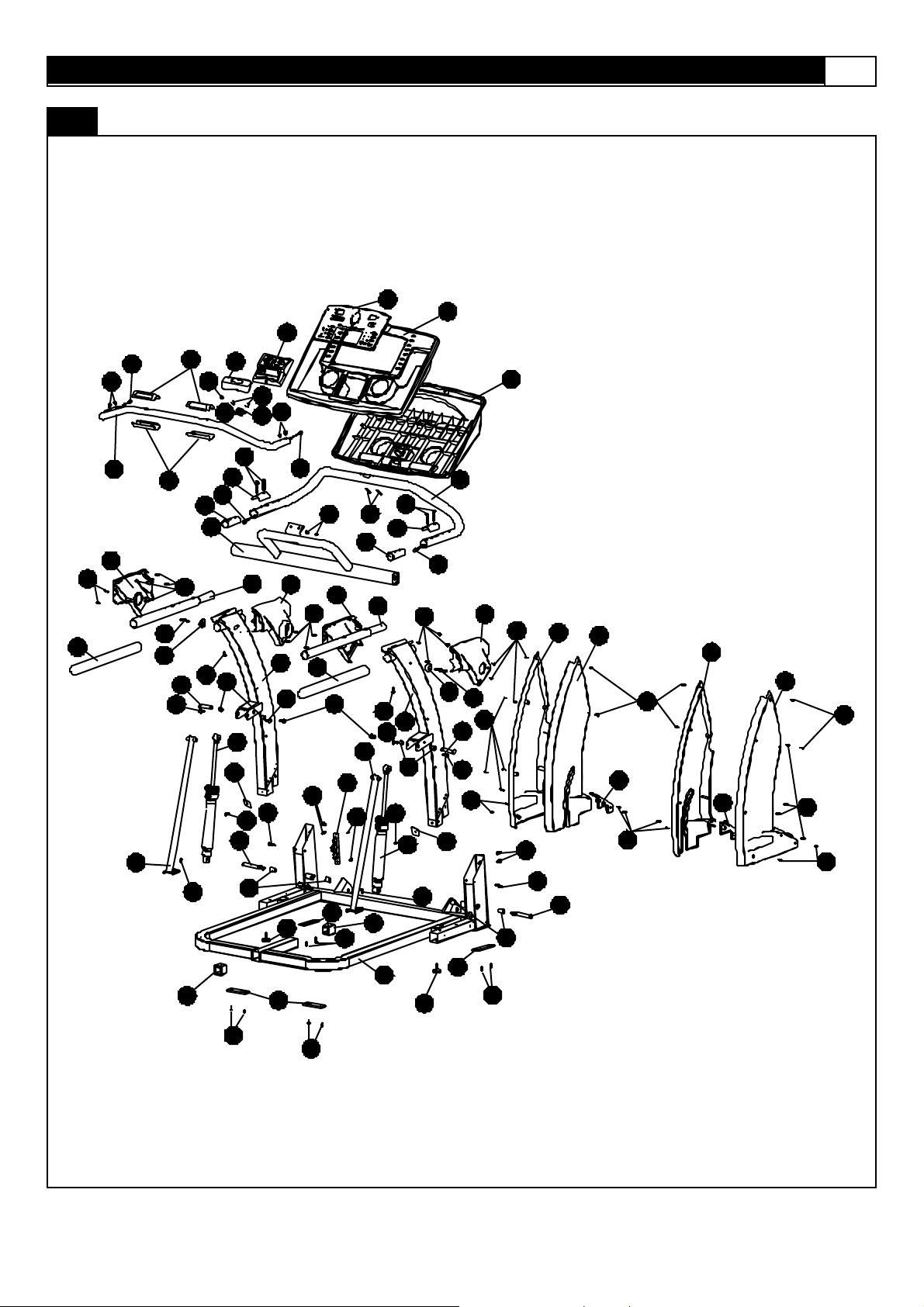
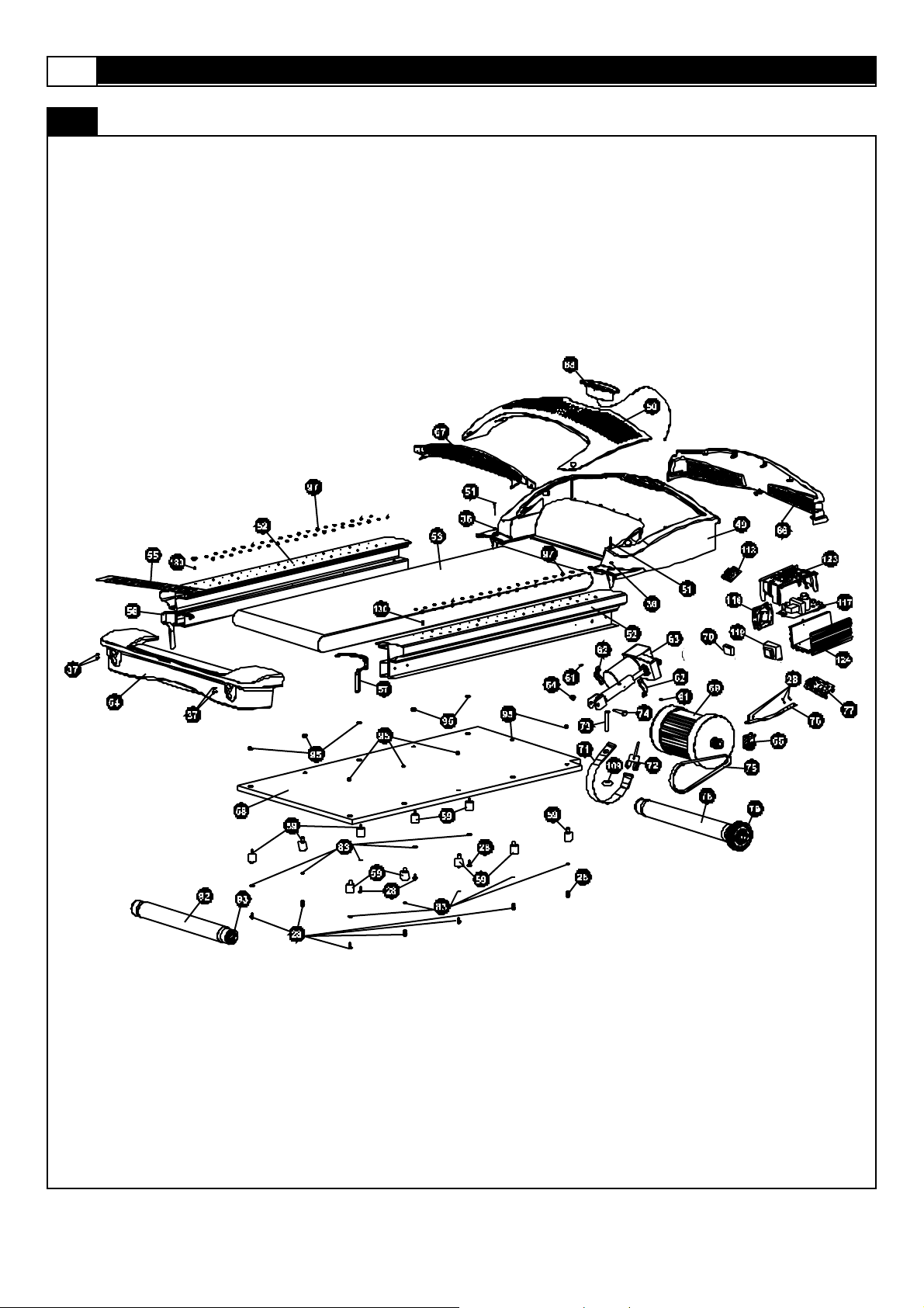
A MAJORI T Y OF THE PAR TS SHOWN HERE HAVE BEEN PREASSEMBLED AT THE FAC TORY.
PARTS DIAG RAM
9
1
2
16
114
116
3
7
25
28
111
112
115 40
113
110
105
112
15 11
22
26
106
29
107
30
31
16
4
104
105
116
12
3
23
15
25
24
27
47
107
48
5
34
7
3
8
19
14
24
28
32
16
40
108
10
8
14
16
18
109
21
24
27
110
20
22
26
17
38
5
112
109
106
13
8
41
42
43
44
18
9
21
24
8
28
9
2
30
31
8
45
46
8
8
9
8
7
28
5
32
3
3
7
33
34
37
35
37
10 MOMENTUM T7 TREADMILL
A MAJORI T Y OF THE PAR TS SHOWN HERE HAVE BEEN PREASSEMBLED AT THE FAC TORY.
PARTS DIAG RAM
www.greenmasterfitness.com.tw
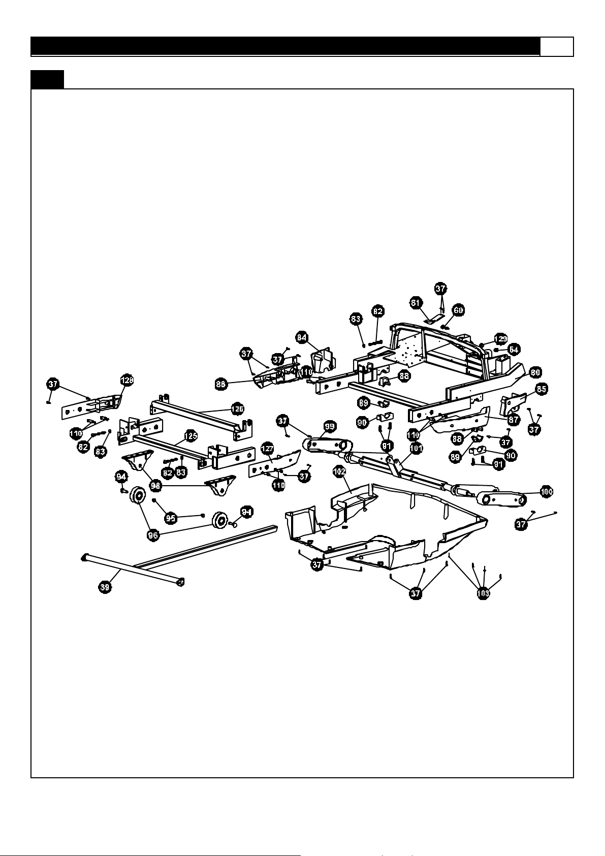
A MAJORI T Y OF THE PAR TS SHOWN HERE HAVE BEEN PREASSEMBLED AT THE FAC TORY.
PARTS DIAG RAM
11
12 MOMENTUM T7 TREADMILL
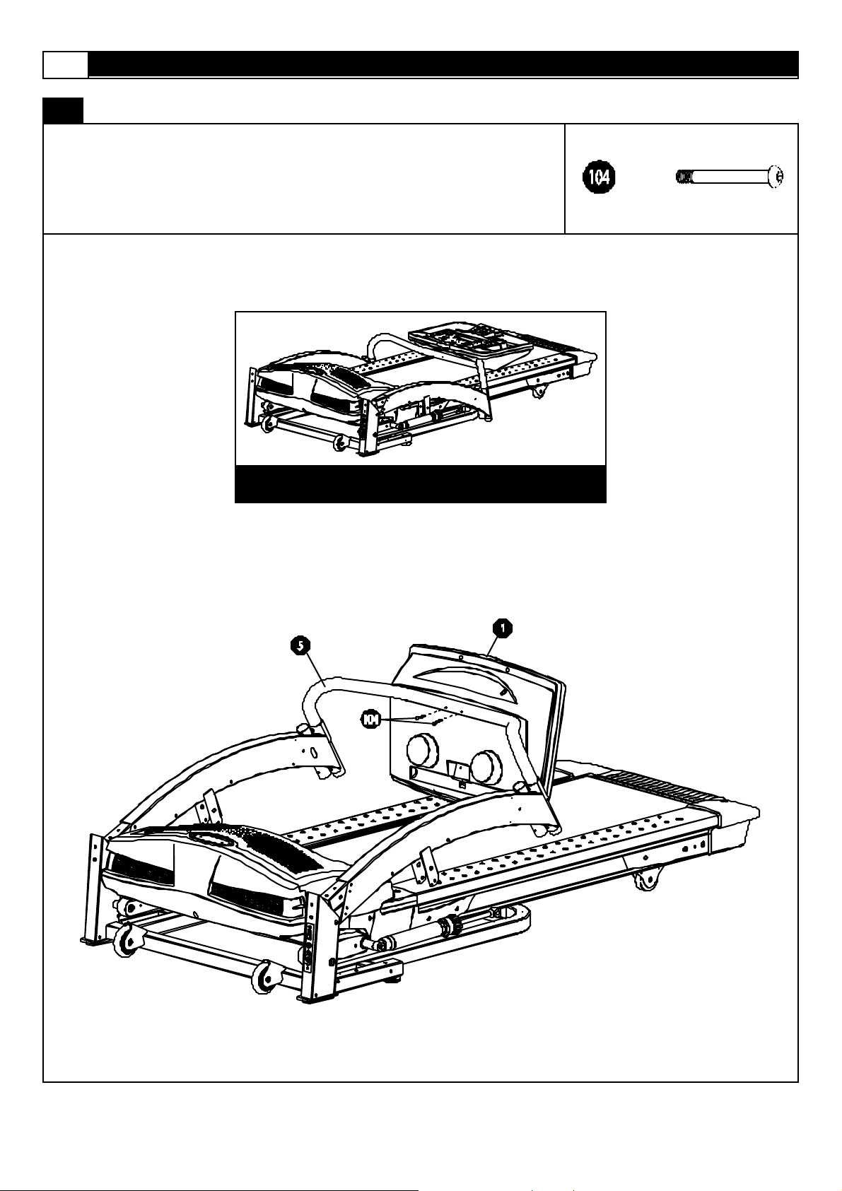
ASSEMBLY
STEP 1:
R emove your treadmill from the cart on and place it on the f loor in an open area as shown
in FI G. 1.
Secure t he Com put er (1) t o the Console Tube (5) us ing two Console Screws (104).
x2
FIG. 1
 Loading...