

Momentum Sales & Marketing Modbus Plus 170 PNT User Manual

170 PNT Series
Modbus Plus Communication
Adapters
for Momentum
User Guide
870 USE 103 00 Version 2.0
31002940.00
31002940 00

2 870 USE 103 00 May 2001

Table of Contents
About the Book. . . . . . . . . . . . . . . . . . . . . . . . . . . . . . . . . . . . . . .5
Chapter 1 Introduction. . . . . . . . . . . . . . . . . . . . . . . . . . . . . . . . . . . . . . . . . .7
At a Glance . . . . . . . . . . . . . . . . . . . . . . . . . . . . . . . . . . . . . . . . . . . . . . . . . . . . . . 7
Product Overview . . . . . . . . . . . . . . . . . . . . . . . . . . . . . . . . . . . . . . . . . . . . . . . . . 8
Status Indicators . . . . . . . . . . . . . . . . . . . . . . . . . . . . . . . . . . . . . . . . . . . . . . . . . 10
Address Switches . . . . . . . . . . . . . . . . . . . . . . . . . . . . . . . . . . . . . . . . . . . . . . . . 12
Ports and Cabling . . . . . . . . . . . . . . . . . . . . . . . . . . . . . . . . . . . . . . . . . . . . . . . . 15
Chapter 2 Assembling a Communications Adapter and I/O Base. . . . . .17
At a Glance . . . . . . . . . . . . . . . . . . . . . . . . . . . . . . . . . . . . . . . . . . . . . . . . . . . . . 17
Connections Between the Adapter and I/O Base . . . . . . . . . . . . . . . . . . . . . . . . 18
Assembling the I/O Base and the Adapter . . . . . . . . . . . . . . . . . . . . . . . . . . . . . 19
Labeling the Assembled Module. . . . . . . . . . . . . . . . . . . . . . . . . . . . . . . . . . . . . 21
Disassembling an Adapter from an I/O Base . . . . . . . . . . . . . . . . . . . . . . . . . . . 23
Chapter 3 Using Modbus Plus for Distributed I/O Servicing . . . . . . . . . .25
At a Glance . . . . . . . . . . . . . . . . . . . . . . . . . . . . . . . . . . . . . . . . . . . . . . . . . . . . . 25
Strategies for Distributed I/O Servicing. . . . . . . . . . . . . . . . . . . . . . . . . . . . . . . . 26
Network Configuration. . . . . . . . . . . . . . . . . . . . . . . . . . . . . . . . . . . . . . . . . . . . . 27
Modbus Plus Network Layouts . . . . . . . . . . . . . . . . . . . . . . . . . . . . . . . . . . . . . . 28
Chapter 4 How Communication Adapters Handle Messages . . . . . . . . .31
At a Glance . . . . . . . . . . . . . . . . . . . . . . . . . . . . . . . . . . . . . . . . . . . . . . . . . . . . . 31
How Messages Are Defined in the Application. . . . . . . . . . . . . . . . . . . . . . . . . . 32
How Messages are Transacted. . . . . . . . . . . . . . . . . . . . . . . . . . . . . . . . . . . . . . 33
Chapter 5 Communication Access Registers . . . . . . . . . . . . . . . . . . . . . .35
At a Glance . . . . . . . . . . . . . . . . . . . . . . . . . . . . . . . . . . . . . . . . . . . . . . . . . . . . . 35
Overview of Register Types . . . . . . . . . . . . . . . . . . . . . . . . . . . . . . . . . . . . . . . . 36
Data Registers. . . . . . . . . . . . . . . . . . . . . . . . . . . . . . . . . . . . . . . . . . . . . . . . . . . 38
Configuration Registers. . . . . . . . . . . . . . . . . . . . . . . . . . . . . . . . . . . . . . . . . . . . 39
Status Registers . . . . . . . . . . . . . . . . . . . . . . . . . . . . . . . . . . . . . . . . . . . . . . . . . 41
3

4 870 USE 103 00 May 2001

About the Book
At a Glance
Document Scope This manual describes the functionality of the 170 PNT Series Modbus Plus
Communication Adapters .
The following information is an introduction to this manual:
Function: The Modbus Plus Communication Adapters can be connected to any
Momentum I/O base to create a functional I/O module.
The adapters provide direct connection to the Modbus Plus network, enabling a
programmable controller to communicate with field devices wired to the I/O base
terminals.
The controller on the network can read from the input terminals and write to the
output terminals of the I/O base using Modbus Plus Peer Cop or MSTR Function
Block messaging.
Data Format: Data bits are transferred in the IEC forma t. This is the standa rd data
format for the Momentum product line.
Models:
Model 170 PNT 110 20 has one Modbu s Plus port f or con nectio n to a netw ork wit h
a single trunk cable.
Model 170 PNT 160 20 has two ports for conn ection to eith er a single-c able or dualcable network.
Validity Note The data and illustratio ns found in th is book are no t binding. We reserve the rig ht to
modify our products in line with our policy of continuous product development. The
information in this document is subject to change without notice and should not be
construed as a commitment by Schneider Electric.
870 USE 103 00 January, 2001 5

Product Related
Warnings
Schneider Electric assumes no responsibility for any errors that may appear in this
document. If you have any suggestions for improvements or amendments or have
found errors in this publication, please notify us. No part of this document may be
reproduced in any form or by any means, electronic or mechanical, including
photocopying, without express w ritten perm ission of the Publisher, Schneider
Electric.
User Comments We welcome your comments about this document. You can reach us by e-mail at
TECHCOMM@modicon.com
6 870 USE 103 00 May 2001

Introduction
1
At a Glance
Purpose This chapter gives an overview of the Momentum Modbus Plus Communication
Adapter models 170 PNT 110 20 and 170 PNT 160 20 and describes their status
indicators, address switches, ports and cabling.
What’s in this
Chapter?
This chapter contains the following topics:
Topic Page
Product Overview 8
Status Indicators 10
Address Switches 12
Ports and Cabling 15
870 USE 103 00 May 2001 7
Introduction
Product Overview
Overview This section provides an overview of the features and function of the Momentum
Modbus Plus Communication Adapt ers.
Function The Modbus Plus Communi cation Adapters can be connec ted to an y Momentu m I/
O base to create a functional I/O module.
The adapters provide direct connection to the Modbus Plus network, enabling a
programmable controller to communicate with field devices wired to the I/O base
terminals.
The controller on the network can read from the input terminals and write to the
output terminals of the I/O base using Modbus Plus Peer Cop or MSTR Function
Block messaging.
Data Format Data bits are transferred in the IEC format. This is the st andard data format for the
Momentum product line.
Models Model 170 PNT 110 20 has on e M od bus Plu s port for c on nec tio n t o a netw o rk wi th
a single trunk cable.
Model 170 PNT 160 20 has two po rts for connec tion to either a si ngle-cab le or dual-
cable network.
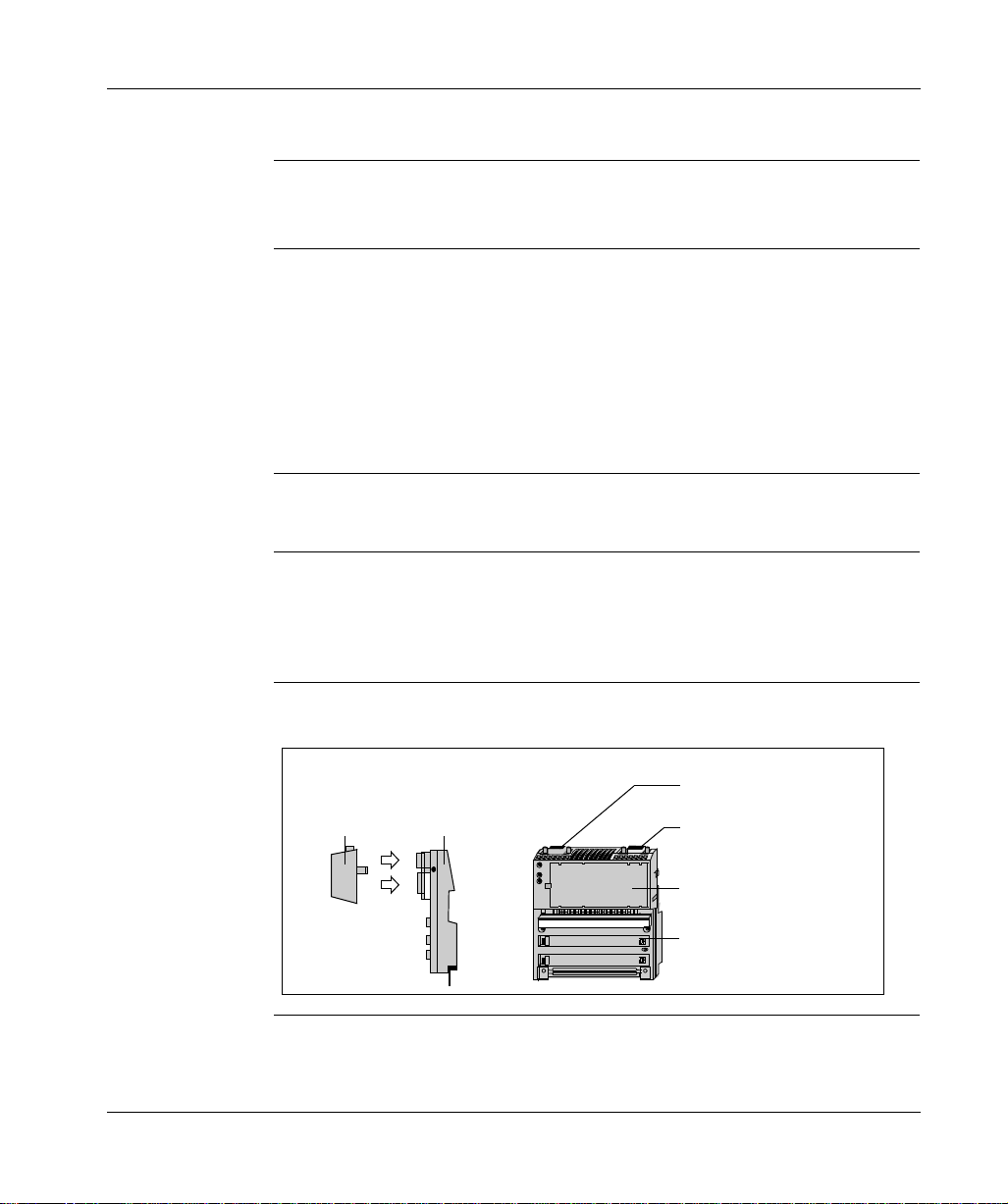
Diagram The diagram below shows a Modbus Plus Communication Adapter m ounted on a
typical I/O base.
Side
View
Communication
Adapter
8
I/O Base
Front
View
Modbus Plus Port B
(170 PNT 160 20 only)
Modbus Plus Port A
(both models)
Communication
Adapter
I/O Base
870 USE 103 00 May 2001

Introduction
Environmental
Specification
The adapter conform s to the enviro nmental specificat ion for the I/O b ase upon which
it is mounted. For further information refer to the Momentum I/O Bases User
Manual, part number 870 USE 002 00.
870 USE 103 00 May 2001 9
Introduction
Status Indicators
Overview This section describes the status indicators fo r each model, gives a diagram of the
indicators, and explains how to interpret the indicator patterns.
Indicators Each model has a front panel indicator showing its network communication status.
The dual-cable model has two additional indicators which identify communication
errors on the two cable paths.
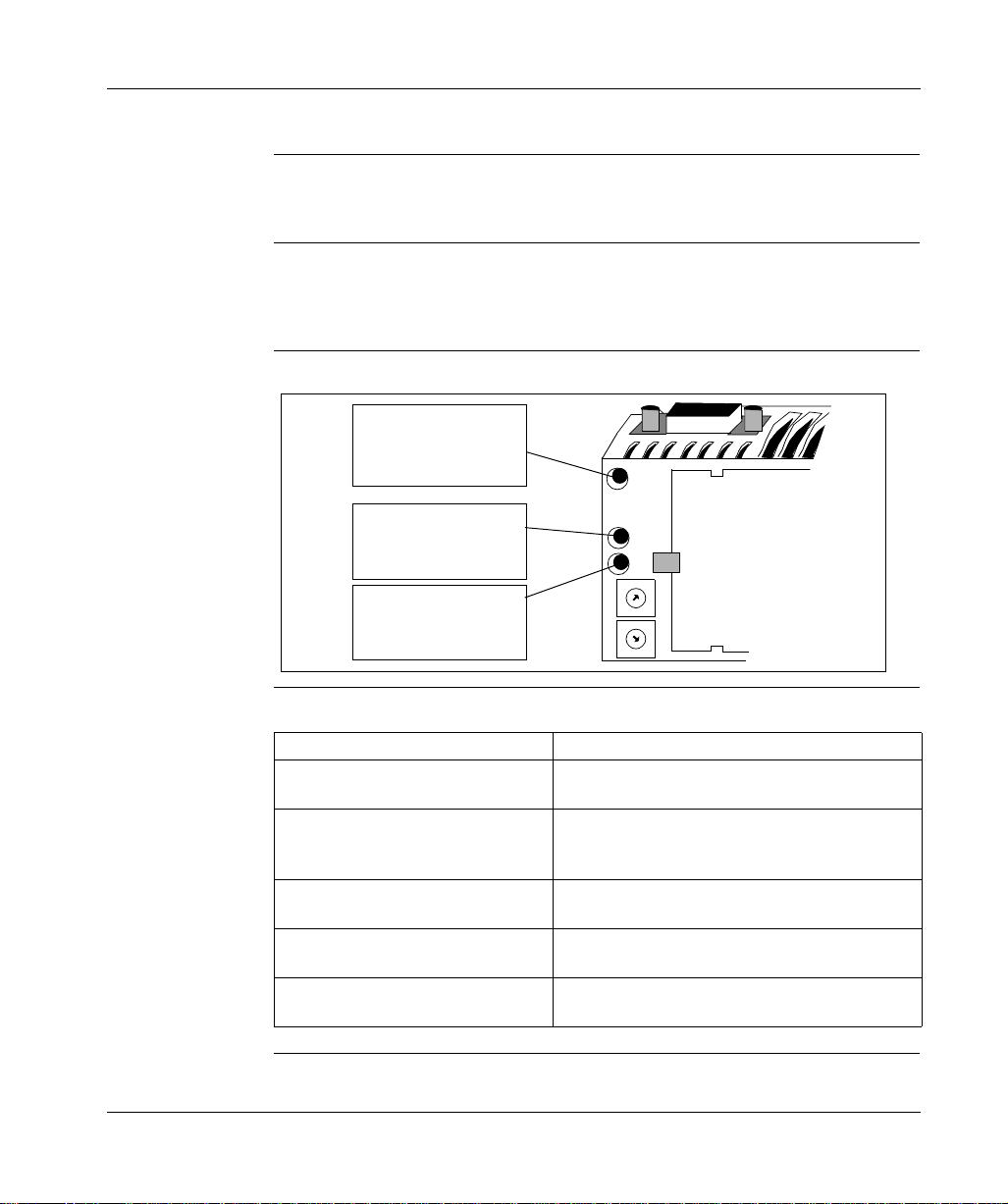
Diagram The communication status and error indicators are shown in the diagram below
Modbus Plus
Communication Active
(Green)
(All models)
Communication Error
Channel A
(Red)
(170 PNT 160 20 only)
Communication Error
Channel B
(Red)
(170 PNT 160 20 only)
MB+
ACT
ERROR
A
B
0
9
8
7
6
0
9
8
7
6
1
2
3
4
5
1
2
3
4
5
Modbus Plus
Active Indicator
Patterns
10
The table below describes the status associated with each active indicator pattern.
Indicator Pattern (Green) Status
Six flashes/second Normal operating state. All nodes on a healthy
network flash this pattern.
One flash/second The node is off-line. After being in this state for 5
seconds, the node attempts to go to its normal
operating state.
Two flashes, then OFF for 2 seconds The node detects the network token being passed
among other nodes, but it never receives the token.
Three flashes, then OFF for 1.7
seconds
Four flashes, then OFF for 1.4 sec onds The node has detected another node using the
The node does not detect any token passing on the
network.
same address.
870 USE 103 00 May 2001

Introduction
Modbus Plus
Channel Error
Indicators
Model 170 PNT 160 20 displays the following error indicator patterns:
Indicator (Red) Status
Channel A Error Communications error at network port A.
Channel B Error Communications error at network port B.
870 USE 103 00 May 2001 11

Introduction
Address Switches
Overview This section describes the address switches and explains how to use them to set the
module address.
Two Rotary
Switches
Guidelines for
Node Addresses
Addresses Must
Match
Each Modbus Plus Commun ication Adapter has two rotary switches on the lower left
portion of the front panel. These switches are used to set the Modbus Plus node
address.
Follow these guidelines when setting node addresses:
l
The node address should be assigned by your network administrator.
l
Each node must have a unique address in the range 1... 64.
l
Duplicate addresses are not allowed.
l
Addresses are assigned logically and are not dependent upon the physical
locations of the node devices.
l
Starting at address 1, the lowes t addresses should be assi gned to programmable
controllers. Commu ni cat ion a dap ters s hou ld be assigned the next a ddre sses i n
direct sequence.
The node address is al so defi ned in the Peer C op Ta ble an d MSTR funct ion blo cks
of the user’s application program. The address defined in the application program
must match the one set by the adapter's front panel switches.
12
870 USE 103 00 May 2001
Introduction
Example of Node
Address
Assignment
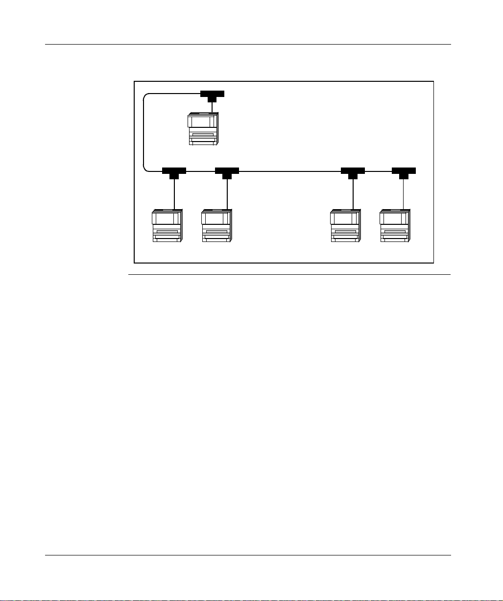
The figure below shows typical address assignments for a network with one
controller and four communication adapters.
Node 1
Programmable Controller
with Modbus Plus Port
(Assigned Node Address 1)
Modbus Plus
Communication
Adapters
with
I/O Bases
Node 4
Node 2Node 5Node 3
870 USE 103 00 May 2001 13
Introduction
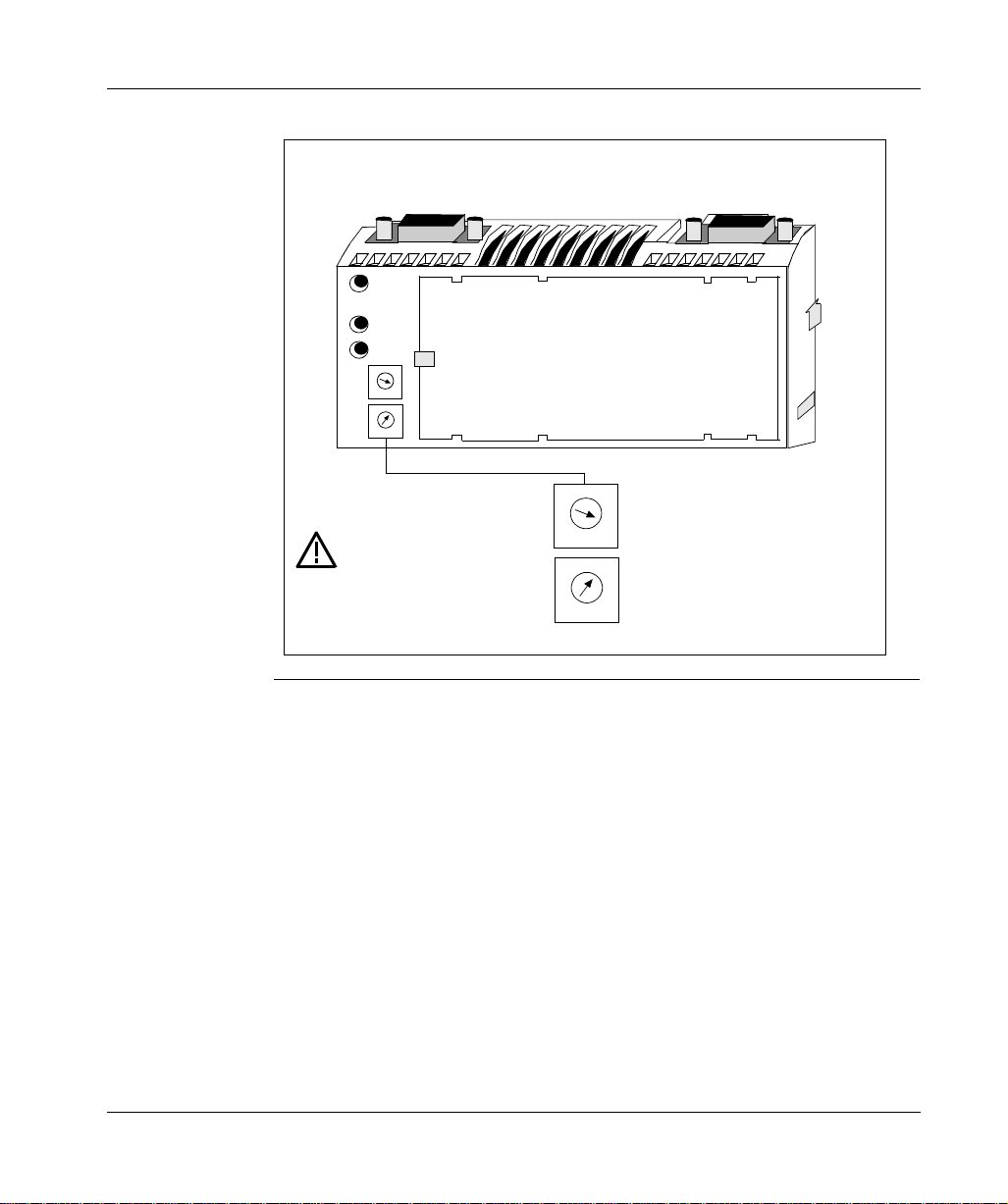
Setting the
Switches
The figure below illustrates how to set a Modbus Plus Node Address.
Do not install any adapter unless you have set
its Modbus PLus address for your application.
MB+
ACT
ERROR
A
B
0
1
9
2
8
X10
3
7
4
6
5
0
1
9
2
8
3
X1
7
4
6
5
X10
See your network
administator to get
the node address for
each adapter.
This example sets the address to 31.
X1
Node
0
1
9
8
7
6
5
Address
2
3
4
10... 19
20... 29
30... 39
0
1
9
2
8
3
7
4
6
5
40... 49
50... 59
60... 64
1... 9
Upper
Switch
0
1
2
3
4
5
6
Lower
Switch
1... 9
0... 9
0... 9
0... 9
0... 9
0... 9
0... 4
14
870 USE 103 00 May 2001
 Loading...