

Momentum Sales & Marketing MO8ME User Manual

mo8me
Mix Engine with mrc (The “Tweak”) Unit
Manual
Pro Co Sound, Inc.
225 Parsons Street | Kalamazoo, MI 49007
1-888-253-7360 | www.procomomentum.com

Warranty
Pro Co Sound guarantees Momentum for fi ve years, any excuse, even abuse. If you need to return the
Momentum unit(s), ship them to Pro Co Sound in the original carton or a suitable shipping container via
insured freight. Pro Co will return the Momentum unit(s) to you, free of charge including return postage.
Once out of Warranty, Pro Co also offers service on all its products.
Customer Responsibility:
Please read the owner’s manual thoroughly before operating the system. Complete the Warranty Card
within ten days after receipt of your Momentum system. Mail the card to us or register your product on line
at www.procomomentum.com.
The Warranty is subject to the following conditions:
1. Pro Co Sound or its authorized representative or dealer must perform all warranty servicing of the
units, otherwise all aspects of this warranty are void.
2. All tamper-proof seals on the unit(s) must be intact in order for the unit(s) to be serviced as a
warranty claim.
How obtain Warranty services:
If, after following all of the operating instructions in this manual, you fi nd that service or support is still
needed:
1. First contact the dealer or contractor from which you purchased your Momentum product for help.
2. If your problem is not resolved after contacting your dealer, call Pro Co Sound at 1-800-253-7360 and
ask for Momentum Service. Our hours are 8:00 a.m. to 6:00 p.m. EST, Monday through Friday.
If the problem cannot be resolved remotely , Pro Co Sound ma y, at its discretion, advance the replacement of
the defective unit(s) and at that time provide a Return Authorization number by which the defective unit(s)
can be returned for credit or repair.
Momentum mo8me Manual
Revision Date: 5/28/2008
2

Table of Contents
Warranty
Safety Precautions
Welcome
Thank You
Unpacking
Chapter 1: Overview
Momentum System
Features
Description of mo8me
The mo8me
The mo8me Enclosure
Front & Rear Panel
Contractor Panel
mcr (The Tweak)
Chapter 2: Connection and
Startup
Power
Network Wiring
Copper Wiring
Copper Connection
Fiber Connection
Network Confi guration
Setup
Network Clock Sync
Using the Control Panel
Setting Device
Start Channel
IP Address
Sample Rate
Chapter 3: Control Panel
Functions
F1 and F2 Functions
Description of Functions
10
11
11
11
11
11
12
13
13
13
14
14
14
14
15
15
16
2
4
5
5
5
6
6
6
6
7
8
9
9
9
Chapter 4: The Tweak;
Overview & Set Up
Menu Layout
Overview
Powering Up
Opening Screen
Communications Time Out Screen
Set Up Menu
Navigating to the Setup Menu
Description of Setup Menu
Setting the Routing
Connection to a mo8me
Selecting Mono or Stereo Mode
Selecting Default Mix & Master User
Setting Time-out & Back Light
Assigning Your Tweak an ID
Enabling Password
Chapter 5: The Tweak;
Mixing
Main Mix Menus
Current Mix Menu
Channel Mix Menu
Channel Menu
Setting Your Input Levels
Adjusting Volume Levels
Naming Channels
Adjusting and Clearing EQ Levels
Setting Output Levels
Setting Panning for Stereo Channels
Selecting a Solo Channel
Muting a Channel
Output Master Levels
Saving Mixes
Recalling Mixes
Chapter 6: mo8me Specifi cations
18
18
19
20
20
21
22
22
23
23
24
24
25
26
26
27
28
28
29
29
29
30
30
30
30
31
32
32
33
34
35
36
37
Momentum mo8me Manual
3
Safety Precautions
Always follow the basic precautions listed below to avoid the possibility of physical injury to
you or others, or damage to the device or other property. These precautions include, but are
not limited to, the following:
To reduce the risk of fi re or electrical shock, do not expose
any part of your Momentum System to rain or moisture.
To reduce the risk of electrical shock, do not remove cover. There are no
user serviceable parts inside. Refer servicing to service personnel.
Use Extreme Caution!
Before making adjustments to your Momentum system, be aware that certain actions could possibly
damage your hearing and/or the audio system itself. Think through your actions and the possible
ramifi cations of your adjustments. Proceed with caution and follow these important Safety Instructions:
1. Read these instructions carefully.
2. Retain these instructions for future reference.
3. Heed all warnings.
4. Follow all instructions.
5. Do not use any part of this apparatus near water.
6. Do not block any ventilation openings.
7. Do not install near any heat source.
8. Do not defeat the safety purposes of the polarized or grounding type plugs.
9. Do not use the Momentum power supply for any purpose other than stated in this manual.
10. Only use Pro Co recommended accessories with any Momentum device.
Momentum mo8me Manual
4

Welcome
Thank You
Thank you for your recent purchase of the Pro Co Momentum mo8me. W e hope you fi nd our product
to be versatile and fl exible. The entire line of Momentum products was designed with the intention of
offering optimal fl exibility for a multitude of applications.
Pro Co Sound, a Michigan based business, was founded in 1974. We build audio interface products,
in-ear monitor controllers and facility distribution systems. We continue to live by our mission;
“T o become our customers’ very best partner , by building a world class organization, through continual,
rapid improvement in all that we do, and to share in the successes and failures of our efforts.”
Welcome to the Pro Co Family.
Receiving Your Momentum mo8me
Upon receiving your Momentum System, please check all cartons for damage. If there is damage,
notify the shipper and dealer in that order. Before removing any components of your Momentum
System from the shipping cartons, be sure that the order is complete as expected. Do this by
checking each Momentum System component on your packing slip to be sure it matches the number
of packing boxes and the specifi c type and number of components contained within. Fill out the
warranty cards and send them in! You should fi nd the following in the carton:
1 x mo8me 1 x Antenna*
2 x Rack Ears 1 x One Spot Power Supply
2 x Stage Boots (optional) 1 x mrc (the Tweak)
NOTE: Stage boots may be requested, for no additional charge at time of order.
* Antenna is left unattached to prevent possible damage during shipping. It will need to be
attached after delivery.
Momentum mo8me Manual
5

Chapter 1
Sy
es
Overview
omentum
The Momentum digital snake system by Pro Co is designed to replace traditional analog audio wiring
anywhere audio distribution is needed. By capturing audio at the source, converting it to digital audio
and distributing it over a standard Ethernet network, many of the diffi culties in executing the increasingly
complicated audio systems of today can be simplifi ed. By reducing the amount of fi eld terminations,
installation becomes less time consuming. Texas Instrument, Burr Brown mic preamps and Cirrus Logic
digital converters provide a platform that is as close to analog as possible without the inherent problems
that are associated with traditional wiring.
Flexibility and expandability are enhanced through the use of modules for inputs, outputs and DSPs. Signal
routing becomes as easy as clicking a key . Y ou can place inputs, outputs, DSPs and controls an ywhere on
the Momentum network. Also digital interfaces are available for seamless system integration into many
of the popular formats.
tur
stem
1
The Momentum network uses standard Gigabit Ethernet technology. With using standard Ethernet
technology, the Momentum system can be setup and controlled using standard Ethernet products.
Standard Gigabit Ethernet Protocol•
Power Over Ethernet (PoE) 802.3af Compliant•
Up to 256 total active system inputs•
1.00 ms A/A latency 48k sampling (with DSP)•
Fiber optic option•
Firmware upgradable in the fi eld•
8 mono, 4 stereo or any combination of •
output mixes
Allows 32 input channels from the network •
for the output mixes
32 three band input EQ’s and 8 three band •
output EQs
The “Tweak” wireless remote control allows •
user to access all system mixing functions
48K sampling only•
Clip LED indicators for each output•
Front mounted control panel•
Available with rack mount kit or optional •
stage boots
Onboard memory and programming•
Control via mrc, free pc software, •
Crestron or AMX
Phoenix connector and DB25 options •
available for permanent installations or
easy passive splits
Momentum mo8me Manual
6
Chapter 1
e
Overview
Description of the mo8m
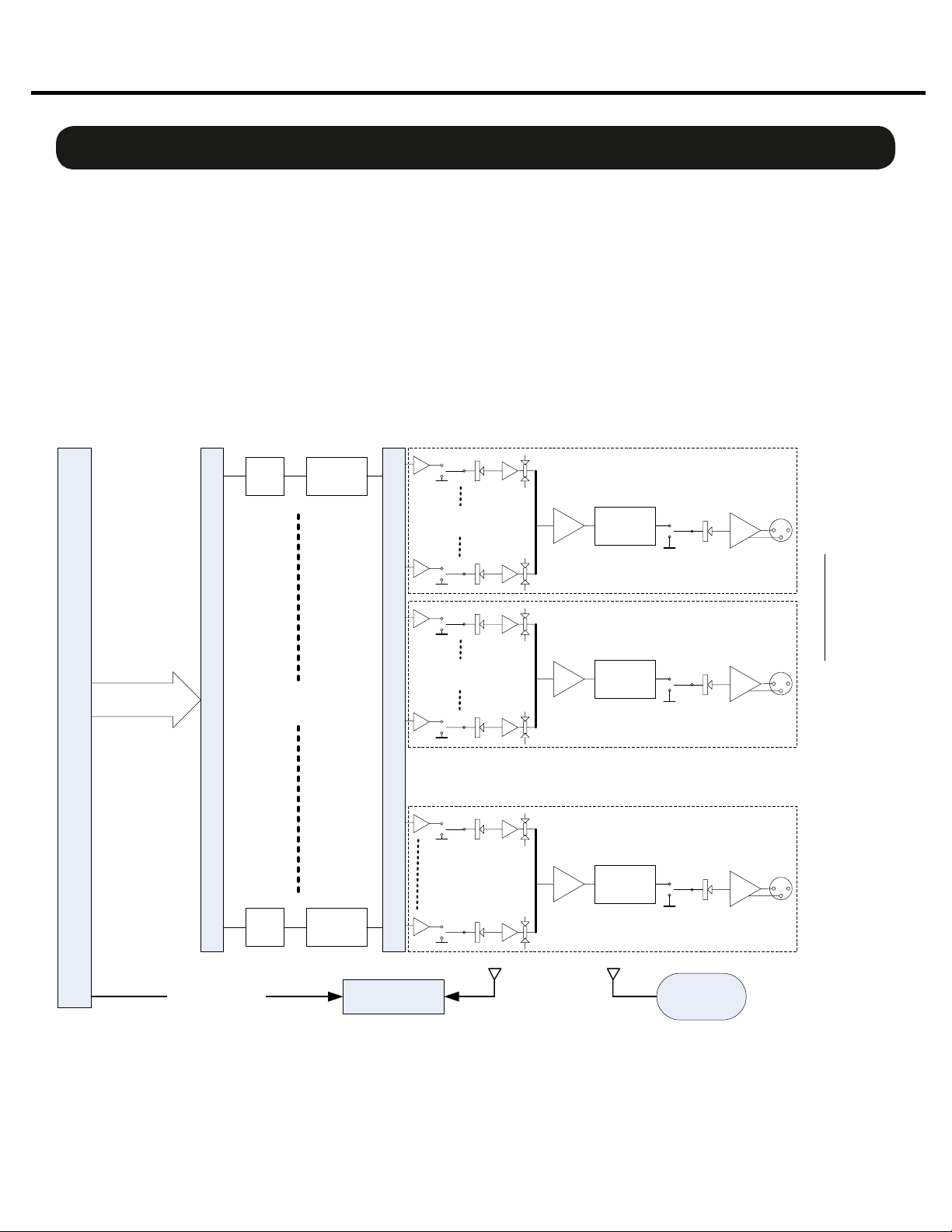
The Momentum mo8me is the DSP based mix engine component of Pro Co’s digital snake system. It utilizes 32
network inputs with 3 band EQ and HPF (high pass fi lter). Output mixes can be mono or stereo and include 3
band EQ and panning control. The mo8me is suitable for numerous tasks such as personal monitor mixing and
distributed audio systems.
Gigabit Ethernet is standard on all Momentum audio products and all components are Power Over Ethernet (PoE)
802.3af compliant. All DSP functions are controlled by the “Tweak”, a wireless user interface, or PC software. In
order for the mo8me to function as it has been designed to, a minimum of one input (mi8) devices must be
present on the Network. A full compliment of options are available to ensure that Momentum can integrate into
your system confi guration.
Block Diagram:
ETHERNET
AUDIO INPUT
MOMENTUM ETHERNET
80Hz
256 CHANNEL ROUTING BUS
80Hz
LF
CUT
32 INPUT
CHANNELS
LF
CUT
3 band EQ
3 band EQ
32 CHANNEL INPUT BUS
MUTE
32 INPUT
CHANNELS
MUTE
32 INPUT
CHANNELS
MUTE
32 INPUT
CHANNELS
PAN
FADER
MUTE
MUTE
FADER
PAN
3 band EQ
3 band EQ
8 MONO OUTPUTS or 4 STEREO OUTPUTS
PAN
FADER
3 band EQ
MUTE
OUTPUT
1/ 1L
Stereo
Link
Select
OUTPUT
2/ 1R
OUTPUT
8/ 4R
ETHERNET CONTROL
Momentum mo8me Manual
DSP
CONTROL
ZigBee 2,4GHz
300' RF
CONTROL
TWEEK
RF REMOTE
7
Chapter 1
Index
D
abo
s
3
y
Th
y
s
D
t
D
A
a
c
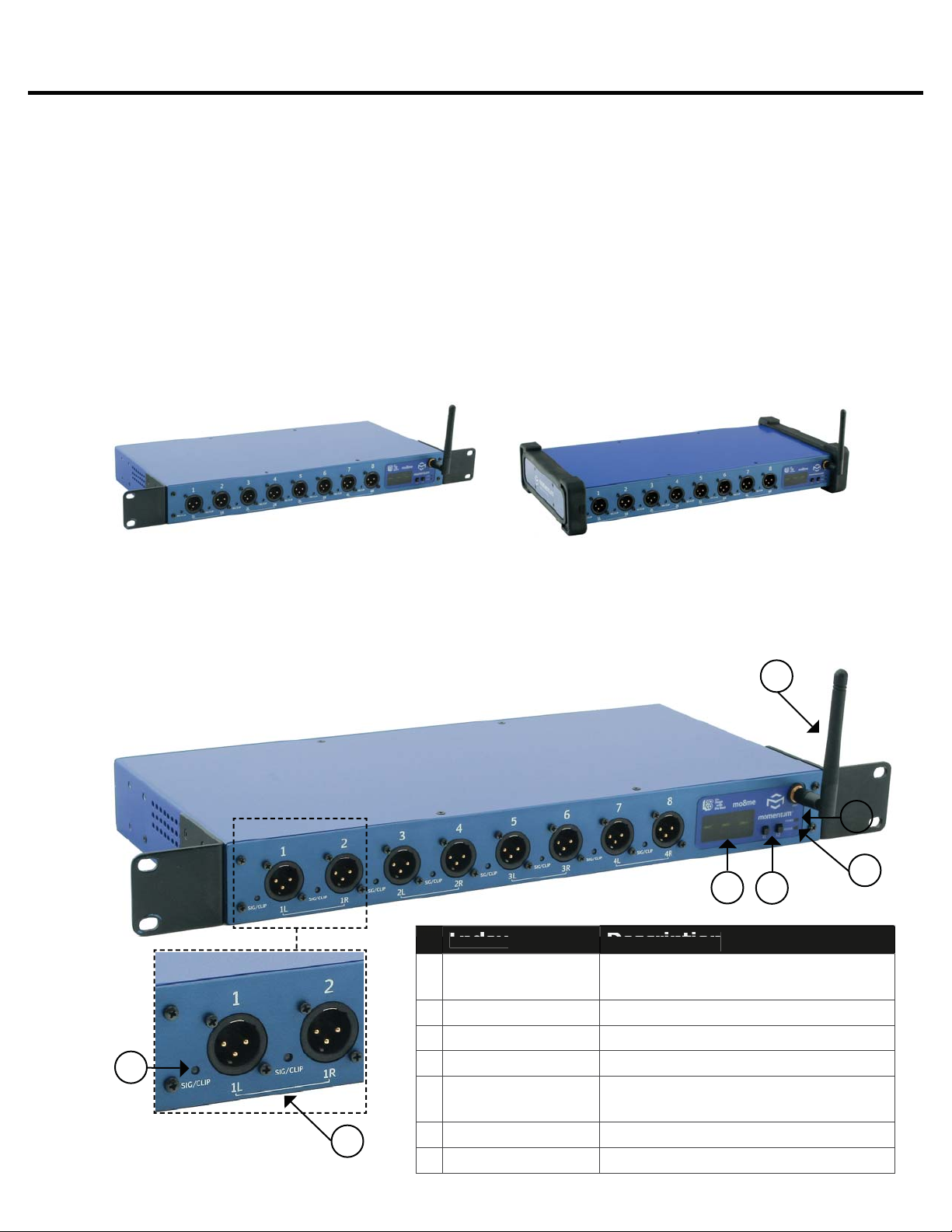
The mo8me Enclosure
The mo8me enclosure can be used in a number of different confi gurations depending on the needs
of the end user. Units are shipped with rack ears, which can be front or rear mounted or can rotate
for vertical or horizontal surface mounting. Optional rubber stage boots allow the units to be used as
stage boxes.
An optional contractor panel can be ordered, which then allows the end user to terminate all analog
connections with simple “phoenix” screw terminal connectors or utilize a standard DB25 “break out
cable” instead of the front panel XLR connectors. This also allows passive “splitting” of the analog
signals if needed. Pro Co offers whatever breakout cables you need. Just ask for them when you
order your system.
Overview
mo8me Front View with Rack Ears
mo8me Front View with optional Stage Boots
Front Panel
The front of the mo8me has a 2-key control panel, eight channels capable of any combination of
eight mono and four stereo output mixes and an antenna for remote mixing. Each channel has one
signal / clip LED indicator that is visible on the front panel.
The control panel includes a power LED, status LED,
a 3-digit readout display and control keys.
7
6
1
Momentum mo8me Manual
5
3
4
ignal/Clip LE
tereo Channel mo8me
ispla
1 & F1 Selector
tatus LE
2
wer LE
ntenn
Green = -40dB F.S. or above;
Red= -3dB F.S. or
ffers 4 stereo channel
ree character LCD displa
elect and edit mo8me functions
Green = Audio sync present;
Red = Network faul
Green = Digital power OK
Communicates with
ve
r
8

Chapter 1
n
y
TX
is
t
000
dica
s
4
y
o
n
ys
Q
T
ggl
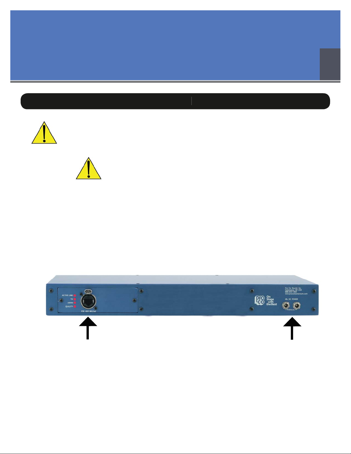
Rear Panel
The rear panel offers network status LEDs for monitoring the unit’s network connection. The
mo8me may be purchased with an optional contractor panel. Shown below.
3
Overview
escriptio
1
2
4
Active Link
1
mIn
Qualit
hows network activit
Indicates that the mo8me
ransmitting data on the network
tes that the mo8me i
connected at one gigabit
Indicates an acceptable Ethernet
ignal to noise rati
Rear View with Contractor Panel
The optional contractor panel allows input analog connection from the rear of the device. These
inputs are connected in parallel to the XLR connectors on the front of the mo8me.
MRC (The “Tweak”)
The “Tweak” or mrc (Momentum remote control) is the companion unit to the mo8me. It is a
wireless remote control that allows the user to create and save personal mixes. See chapter 5 for a
more detailed description of the Tweak’s functions.
Index Descriptio
1
2
8 Soft Ke
Encoder
sed to select functions, E
nds and saved mixes.
urn to to
down to return to previous screen
e channels and push
Momentum mo8me Manual
9
Chapter 2
Connection and Startup
Power
Only use with the power supplies provided by Pro Co Sound.
OR
Only use 802.3af PoE power supplies.
The Momentum output unit requires 48VDC power to operate. There are two ways to power the unit:
Use the 1. Pro Co One Spot power supply. It is shipped with the unit and allows the powering
of only one device. An alternative to the One Spot is the Multi Unit Power Supply (MUPS).
This power supply comes with three jumper cables that will allow up to four units to be linked
together and powered by one MUPS. The MUPS is an additional option and must be ordered
separately.
2
Use a standard 2. Gigabit IEEE 802.3af PoE network switch and power up through the
Ethernet cable. The POE switch must be capable of 15Watts per Ethernet port.
Ethernet port
One Spot or MUPS power supply ports
Momentum mo8me Manual
10
Chapter 2
Wiring
Copper Wiring
Use a minimum of • CAT5E or CAT6 network cable
Maximum cable length is 100 meters•
Maximum cable length with POE is 50 meters.•
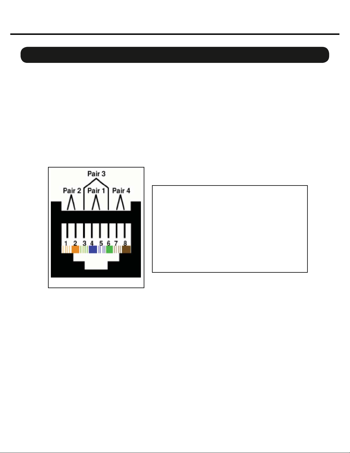
Copper Connection
Use T568B or equivalent connectors when wiring your system. This view shows the color code as •
viewed from the front of the female socket or the rear of the male connector.
Crossover wiring is not needed; the Momentum network interface compensates for unit-to-unit •
connections.
Connection and Setup
etwork
Pin T568B (female) Description
1 Orange/White
2 Orange
3 Green/White
4 Blue/Power
5 Blue/White
6 Green Receive
7 Brown/White
8 Brown Power
T568B
Bi-directional pair +A
Bi-directional pair - A
Bi-directional pair +B
Bi-directional pair +C
Bi-directional pair - C
Bi-directional pair - B
Bi-directional pair +D
Bi-directional pair - D
Fiber Connection (Optional)
The Momentum Fiber option uses ST style connectors and operates at 850nm. The system is fully
IEEE 802.3z Gigabit Ethernet compliant. The following are performance based on the cable type:
220 meter distance use 62.5/125um MMF 160MHz Km Cable
275 meter distance use 62.5/125um MMF 200MHz Km Cable
500 meter distance use 50/125um MMF 400MHz Km Cable
550 meter distance use 50/125um MMF 500MHz Km Cable
Momentum mo8me Manual
11
Chapter 2
Connection and Setup
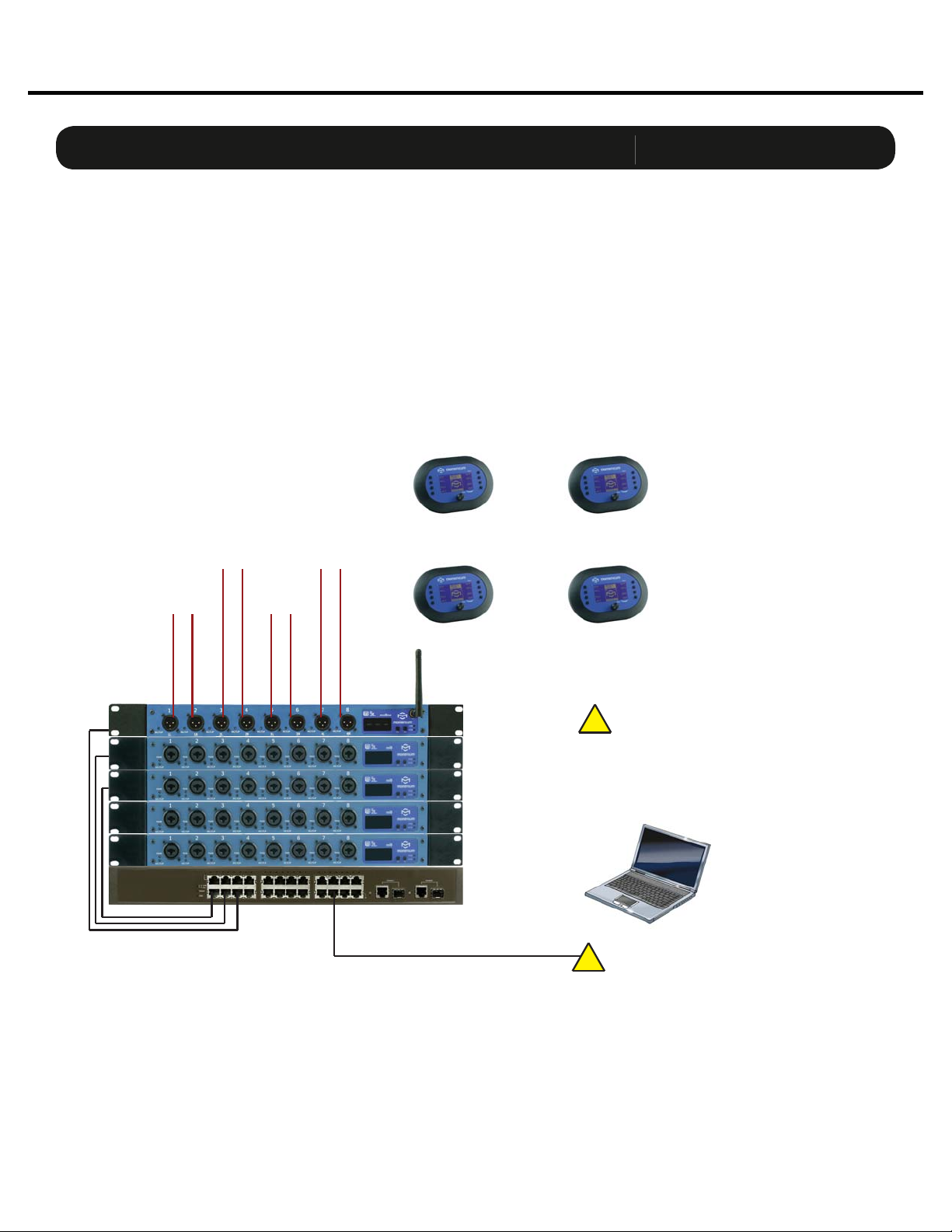
Network Confi gurations
The following are examples of network confi gurations. These samples show confi gurations using ana-
log inputs and outputs. Momentum digital input and outputs or DSP devices use the same methods for
network confi guration.
Using the Momentum system, the network confi guration possibilities are endless. For more information
on advanced confi gurations and support, visit www.procomomentum.com. F or f urther support, con-
tact you local dealer or Pro Co technical support.
Basic Mix System
SHOWN IN STEREO MODE
To In-Ear
Monitors
Mix 2
To In-Ear
Monitors
Mix 1
To In-Ear
Monitors
Mix 3
To In-Ear
Monitors
Mix 4
Wireless
Mix 1 Control
Wireless
Mix 3 Control
mo8me Mix Engine
Chn=001 Adr=005
mi8 Input
Chn=001 Adr=001
mi8 Input
Chn=009 Adr=002
mi8 Input
Chn=017 Adr=003
mi8 Input
Chn=025 Adr=004
Ethernet Switch
Wireless
Mix 2 Control
Wireless
Mix 4 Control
Chn 001 must be present on the
network at all times. This unit will sync
!
the network clock.
Control Device
Momentum mo8me Manual
CAT5E or CAT6
If running over 48 channels, you MUST
!
set the Ethernet port that is connected
to your control PC to multicast filtering.
Multicast MAC 01:15:AB:C6:00:00
(See Network Design White Papers)
12
 Loading...