

Momento UDG, UCG, UTN, USG User Manual
INSTRUCTIONS
6
7028B 06/11 (MBC)
English
T
he thermostat is an electronic on/off
thermostat for temperature control by means of
a
n NTC sensor located either externally or
i
nternally within the thermostat. The thermostat
h
as a built-in ground fault circuit interrupter
(GFCI, Class A). The thermostat and GFCI are
s
uitable for 120-240 V (incl. 208V) 50/60 Hz
p
ower supplies.
The thermostat is for flush mounts in a wall
socket.
P
roduct programme
Thermostats with built-in GFCI
UCG-4991 Programmable thermostat incl.
floor sensor
U
DG-4999 Programmable thermostat with
2 sensors:
f
loor sensor and built-in room
s
ensor
UTN-4991 Non-programmable thermostat
incl. floor sensor
P
ower module with built-in GFCI
USG-4000 Power module without sensor
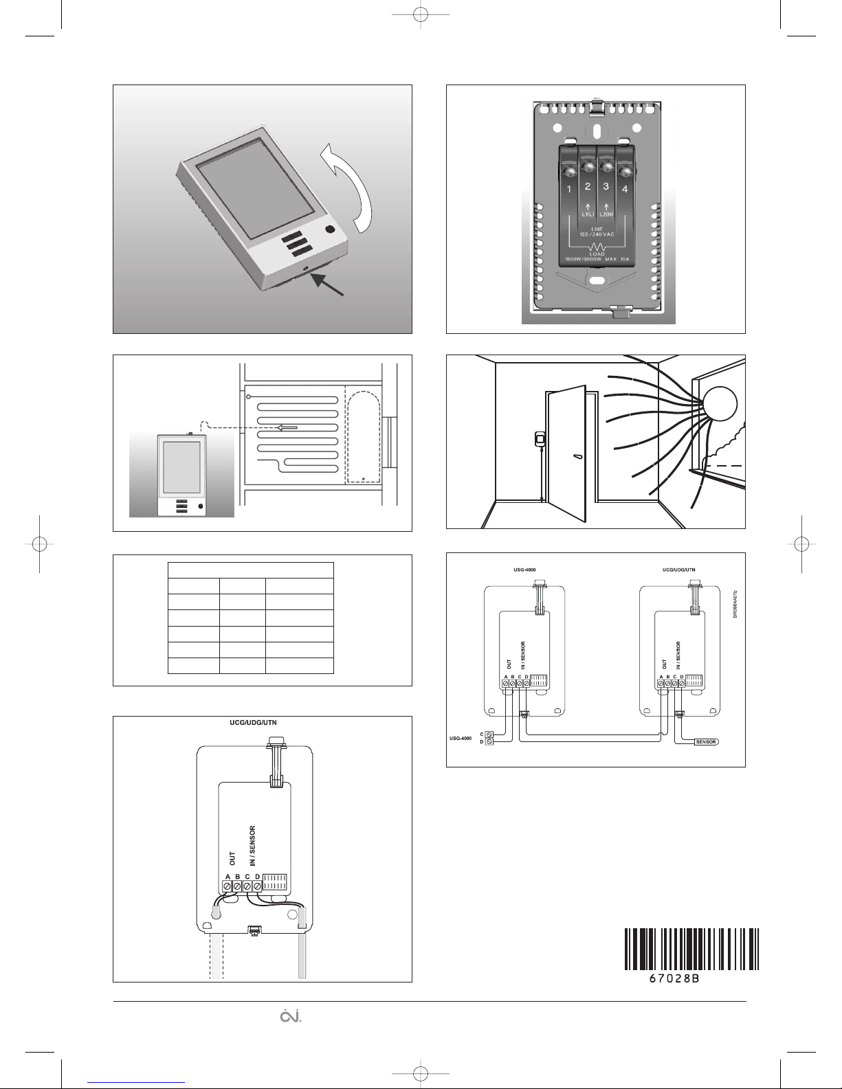
Mounting of floor sensor (fig. 3)
Floor sensor is supplied from SELV (Safety Extra
low Voltage) Circuit, allowing the sensor to be
placed as close to the floor surface as desired
without having to take special account to the
risk of shock at the damage to the sensor cable.
It is not intended that the temperature sensor
wire shall enter through the wall socket
mounting box. The sensor cable shall be
seperated from LINE and LOAD cables. Can be
separated in conduite, inside or outside the
wall. (see fig. 7)
Recommended placed in an non conductive
installation pipe, which is embedded in the floor.
(fig. 3). The pipe must be sealed in the end and
placed as high as possible in the concrete layer.
Alternativerly, the floor sensor is monted directly
in the floor construction. The sensor cable shall
be placed in a separate pipe or be separated
from power cables.
The floor sensor must be centered in between
the heating cable.
Sensor cable can be extended up to 300 ft (100
m.) by means of a separate two-core cable. Two
remaining cores of a multi-core cable which, for
example, supplies current to the floor heating
wires, must not be used. The two-core cable
must be placed in a separate pipe or be
separated from power cables.
Other approved floor sensors can be used if
they comply with the technical specifications
(see fig. 5).
Mounting of thermostat with built-in sensor
(UDG-4999) (fig. 4)
The room sensor is used for comfort
temperature regulation in rooms. The
thermostat should be mounted on the wall
approx. 5.4 ft (1.6 m) above the floor in such a
way as to allow free air circulation around it.
Draughts and direct sunlight or other heat
sources must be avoided.
Mounting of thermostat
I
nstallation
T
O AVOID ELECTRIC SHOCK, DISCONNECT
THE HEATING SYSTEM POWER SUPPLY AT
T
HE MAIN PANEL BEFORE INSTALLING THE
T
HERMOSTAT.
K
EEP THERMOSTAT AIR VENTS CLEAN AND
FREE FROM OBSTRUCTION.
T
his thermostat is an electrical product and
m
ust be installed in compliance with the
National and/or Local Electrical Code.
Installation must be performed by qualified
p
ersonnel where required by law. The
t
hermostat is equipped with a ground fault
circuit interrupter (GFCI, Class A) which requires
that the line and load cables are isolated from
o
ne another for correct operation. The
t
hermostat is designed for resistive load. The
resistive load must not exceed 15 A (1800 W at
1
20 Vac / 3120 W at 208 Vac / 3600 W at 240
V
ac).
During a ground fault, the two lines will be cut
o
ff.
Line cable
D
elivers power from the service panel (breaker
panel or fuse box) to the thermostat.
This cable must only be connected to the
thermostat’s line terminals, marked L1 and L2.
Load cable
Delivers power from the thermostat to the
heating cable.
This cable must only be connected to the
thermostat’s load terminals, marked load 15 A.
1. Use a screwdriver to release the catch (fig. 1),
and remove the front cover
2. Connect cables according to the diagram (fig. 2)
3. Mount the thermostat in the wall socket.
4. Carefully replace the front cover by first
positioning its upper edge and then clicking it
into place.
Temperature sensor
The floor sensor must be connected to
terminals marked “sensor”, terminals C and D.
(fig. 6).
Power module, type USG
If loads of more than 15 A are required,
expansion is possible using power modules.
Power modules can be connected to the live
cable and load cable, see relevant sections.
Maximum distance between thermostat and
power modules is 80 ft (25 m.)
Use field wiring cable, recommended min. 20
AWG. Connect A to C and B to D (fig. 6).
Operation
Types UCG and UDG (with built-in clock):
The first time the thermostat is connected,
time and day must be set. The thermostat will
automatically start up in the menu for setting
time and day.
Type UTN (without built-in clock):
The actual temperature setting is shown and the
thermostat is ready for use.
Checking the GFCI
It is important that the GFCI is checked for
correct installation and function.
To check the GFCI:
Testing can only be performed while the
thermostat is calling for heat.
Adjust the setpoint until the heating symbol ()
a
ppears. Use the “Up” button to increase the
h
eating demand and then press the “OK”
button. Wait 10 seconds to allow the thermostat
t
o adjust to the new setpoint.
T
hen press the “TEST” button.
T
he test is successful if the red light in the
“TEST” button lights up and “GROUND FAULT”
i
s shown on the display. If this does not occur,
c
heck the installation.
Press the “Standby/Reset” button to reset the
GFCI.
T
he red light should go out and the display
r
eturns to normal appearance.
Press the “Down” button to return to the original
temperature setting.
I
f the test fails, check the heating cable and
t
hermostat.
The GFCI should be tested monthly.
I
f during normal operation the GFCI trips
without the “TEST” button being pressed, there
could be a ground fault! To check whether it is a
g
round fault or nuisance tripping, press
“
Standby/Reset”. If this causes the red light to
go off and stay off, it was nuisance tripping and
t
he system is operating correctly. If this does
not occur, there is a ground fault!
Check the heating cable, sensor cable and
thermostat. Replace the defective part.
Programming
See user manual.
Fault location
If the sensor is disconnected or short-circuited,
the heating system is switched off. The sensor
can be checked against the resistance table
(fig. 5).
Error codes
E0: Internal error. The thermostat must be
replaced.
E1: Built-in sensor short-circuited or
disconnected. The thermostat must be
replaced (n/a for UTN-4991)
E2: External sensor short-circuited or
disconnected.
UL Listed for the US and Canada
According to the following standards:
Thermostat: UL 873
CSA C22.2 No. 24.
UL file number: E157297
GFCI: UL 943 4th ed.
CSA C22.2 No. 144.1-06
Classification
The product is a class II device (enhanced
insulation) and must be connected to the
following leads:
Phase L1 (L) 120-240 V ±10%, 50/60 Hz
Neutral L2 (N)
Max. load 15 A (resistive load)
The terminals are suitable for field wiring cables
of 12 to 22 AWG.
Technical data
Supply . . . . . . . . . . . . . .120-240 Vac 50/60 Hz
Load . . . . . . . . . . .max. 15 A (resistive load)
Power . . . . . . . . . . . . . . . .1.800 W at 120 Vac
. . . . . . . . . . . . . . . .3.120 W at 208 Vac
. . . . . . . . . . . . . . . .3.600 W at 240 Vac
GFCI . . . . . . . . . . . .Class A (5 mA trip level)
Temperature range +5 to +40°C, +41 to +104°F
Amb. temp. range . . . .0 to +25°C, +32 to +77°F
Type UDG, UCG, UTN, USG
© 2011 OJ Electronics A/S
67028B-06-11.qxp:57609 30/06/11 9:02 Side 1
F
ig. 1
BR928A07
Sensor
Temp.(˚C)
Value (ohm)
-10
0
10
20
30
64000
38000
23300
14800
9700
Temp.(˚F)
68
86
50
32
-14
Fig. 5
F
ig. 2
1,6m
Fig.4
The trademark is registered and belongs to OJ Electronics A/S · © 2011 OJ Electronics A/S
Fig. 6
1
22
1
BR0964A02
Fig. 7
Celsiair Inc.
2713, boul. Louis XIV
Québec, QC G1C 5S9 Canada
Téléphone : (418) 663-7878
Sans frais : 1 866 930-7878
Télécopieur : (418) 663-7267
info@celsiair.com
www.celsiair.com
67028B-06-11.qxp:57609 30/06/11 9:02 Side 4
 Loading...