

P
P
-
-
P
P
3
3
a
a
8
8
Lii
r
r
L
k
k
g
g
fll
f
h
y
y
h
e
e
t
nii
t
n
r
r
n
n
g
g

Molt Models P-38 Building Instructions Rev A
Molt Models Background Design Philosophy
When I was first introduced to this hobby eighteen years ago I saw my first WWII
warbird and I was hooked. Several years later when I began building radio controlled
model airplanes on my own, I learned that along with the intriguing warbird looks
came a plane that was usually difficult to fly. After a few disheartening attempts with
some larger glow powered warbirds I thought about how great it would be if I could
design a spirited yet forgiving warbird that could be flown in a space the size of a
soccer field. At that time the level of technology was not advanced enough to make
this a reality, but the developments in the last few years have made it possible and
economical.
The Molt Models design philosophy is comprised of methods that enhance scale
appearance and all around flight performance. The first thing you’ll notice about a
Molt Models kit is that the majority of wood parts, illustrations and plans are CAD
based. These items are derived from the same 3D modeling environment that the
plane was designed in. My goal is to cut down on wordy instructions and use a more
visual approach that will get you from kit to airborne in as little time as possible.
Molt Models Parkflyer P-38 Lightning
Thank you for purchasing the Molt Models Parkflyer P-38 Lightning. This kit represents a
true first in parkflyer warbirds in that it possesses characteristics that make it both
enjoyable to build and more importantly, fly. I sincerely hope that you enjoy your new
Molt Models kit. Please visit us at www.moltmodels.com for updates and information
on future kits.
Manual Revisions
Rev A - Figure 18 (wing tip measurement) 3-5/16” was 2-3/16” in “Wing Halves Joined” section
© Copyright 2004 Molt Models. All rights reserved. 2 of 44

Molt Models P-38 Building Instructions Rev A
Molt Models Parkflyer P-38 Lightning Specifications and Kit Requirements
The P-38 Lightning is a fully functional aileron, rudder, elevator, and throttle controlled
aircraft (4 channel). You may build the P-38 Lightning to fly with aileron, elevator, and
throttle only by gluing the rudders to the vertical stabilizers. If you decide to do this I
would recommend that you leave the landing gear off as take off and landing on a
hard surface will be difficult without a rudder. I also recommend leaving the landing
gear off if you intend to fly on grass only. If you fly on a nice hard surface, the P-38
Lightning with all functions and landing gear is quite impressive. On the other hand I
definitely do not recommend you attempt to fly the P-38 Lightning as a rudder,
elevator, and throttle only model.
P-38 Lightning Specifications
Length: 26 in
Wing Span: 38 in
Wing Area: 216 in2
Flying Weight: 10.0 ~ 12.0 oz
Wing Loading: 6.67 ~ 8.00 oz/ft2
Power System: GWS S1 IPS
Functions: Aileron, Elevator, Rudder, & Throttle
Battery Pack: 7.4V, 1200mAh or larger Lithium Polymer
Parts you will need to complete the P-38
Lightning kit:
• (2) GWS IPS (“S1” gearing) and
manufacturer recommend propellers
• (1) 4 channel receiver
• (1) 10A Electronic Speed Control
• (3) Servos (Hitec HS-55 or GWS Pico/Naro)
(4 Channel)
• (2) 12” servo extensions
• (2) Female JST connectors
• (1) Male JST connector
• (1) Red wire, 20” long
• (1) Black wire, 20” long
• (1) Roll of Nelson Lite Film AKA Solite
covering
Supplies and tools you will need to complete
the P-38 Lightning kit:
• Hobby knife and blades
• Stickpins
• Pliers
• 90-degree triangle
• Ruler
• Covering iron
• Fine tip ink pen
• Fine/medium sand paper
• 5-minute epoxy
• Thin CA glue and fine extension tip
• Wood glue
• Wax paper or plan protection plastic
• 3/4" trans p a rent tape
• Masking tape
© Copyright 2004 Molt Models. All rights reserved. 3 of 44

Molt Models P-38 Building Instructions Rev A
General Model Building Tips and Orientation
First and foremost, this kit is NOT for the first time wood kit builder. Having said that, if
you study the plans and instructions and get help from an experienced builder it’s
quite possible to build a nice flying model from this kit. Lastly, keep in mind that this kit
is a reasonably scale model of a real WWII airplane and consists of complex shapes. It
WILL NOT build as easily as the typical box, slab sided laser cut kits that you may have
built.
Please be sure to study the plan sheets and read through the following instructions
before attempting to build your P-38 Lightning. Having a good idea of what to expect
as you progress will cut down on mistakes and allow you to better organize your
project. Checkboxes have been provided in front of each step that allows you to
easily keep track of your work.
Begin each building section by taping the corresponding plan sheet to your building
surface; masking tape works great for this. Next cover the area of the plans you will be
building over with plan protection plastic or wax paper. This will keep your plans from
sticking to your model.
It is often necessary to pin parts of the model over the plan sheet as you progress
through the build. In conjunction, it will be necessary to have a building
surface/board that allow pins to stick into it with ease. I recommend using the smallest
diameter “stick pins” you can find as larger diameter pins can split the wood.
Appropriate sized pins are available in the craft and sewing section of most major
discount stores.
Thin CA glue is suitable for almost a ll the build sections of this model. If another type of
glue is necessary for a certain build section it will be recommended in that segment.
Standing behind the plane orients the left and right side of the model. The plans and
building instructions refer to areas of the model in this manner.
© Copyright 2004 Molt Models. All rights reserved. 4 of 44
Molt Models P-38 Building Instructions Rev A
Build Section #1 – Boom Construction
The booms of the P-38 are constructed in two halves and then glued together to form a single boom.
The boom building section of the plans refer to “Right Boom Components” and “Left Boom
Components”. In add ition, both the Right and Left Boom Components consist of an “Outside Half” and
an “Inside Half”. If you take care to build only one boom half from each of the four boom halves shown
on the plan s you will not have to worry about building incorrect boom parts. To avoid making this
mistake, mark off each boom half shown on the plans as “completed” when you finish them.
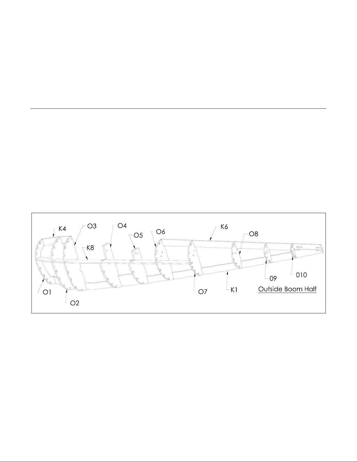
Outside Boom Half
Pin boom keels K1, K4, and K6 over one of the outside boom halves shown on the plans and glue
adjacent edges.
Glue the boom formers O1, O2, O4, O7, O8, O9, and O10 to K1, K4, and K6 making sure they are
perpendicular to the building surface. Be sure to orient each of the boom formers so that the
notches that accept K8 are in a line as you site down the boom.
Install, but DO NOT glue the boom formers O3, O5, and O6.
Glue K8 into the notches of each of the boom formers O1, O2, O3, O4, O5, O6, and O7. Note that
K8 orients O3, O5, and O6 at proper angles that interface the wing. Finish by gluing O3, O5, and O6
to K1, K4, and K6.
Figure 1
© Copyright 2004 Molt Models. All rights reserved. 5 of 44
Molt Models P-38 Building Instructions Rev A
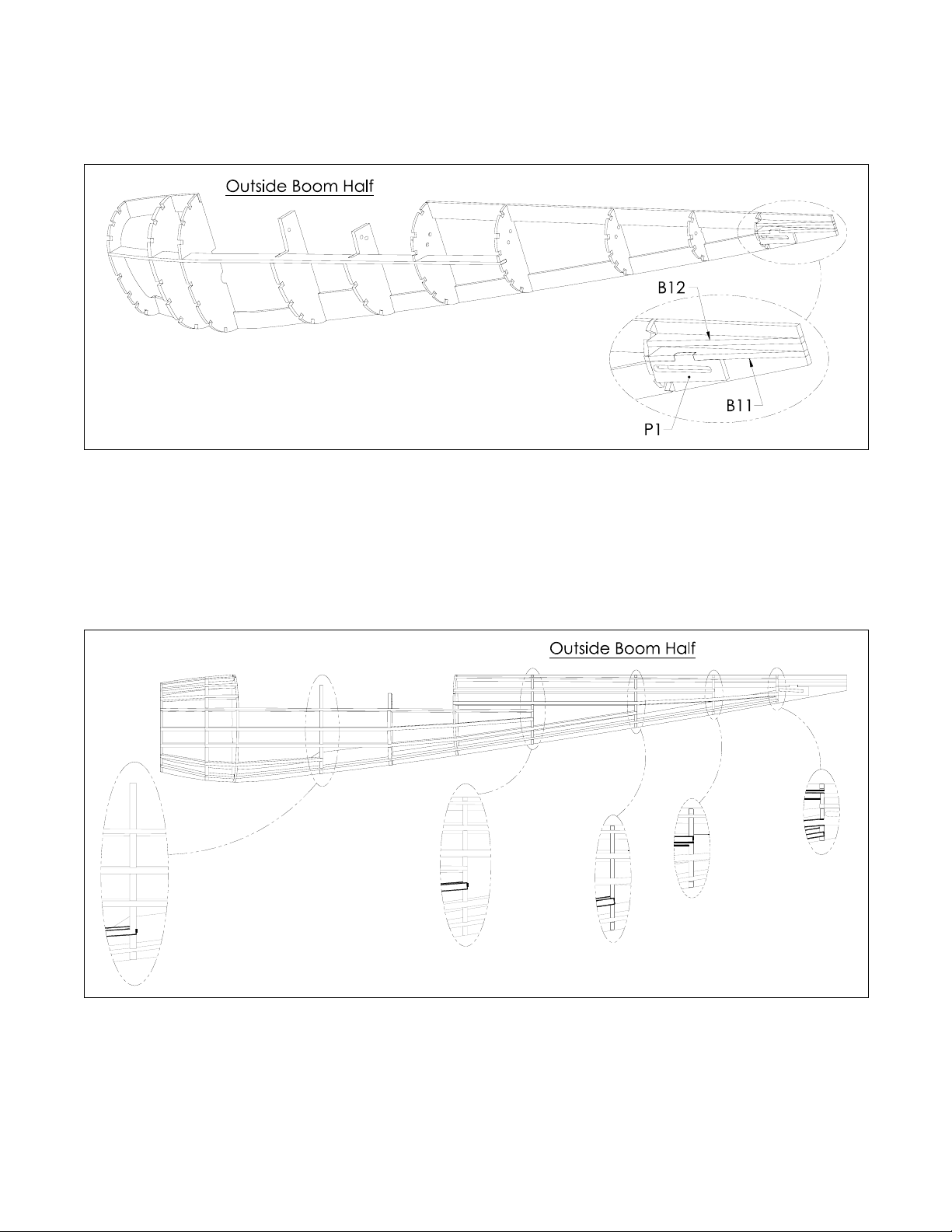
Glue B11 and B12 into the notches of K1, K6, and O10.
Glue pushrod exit P1 to B11 and O10.
Figure 2
Glue 3/32” SQ. Balsa Stringers to the boom formers as shown in Figure 3 and the plans. Figure 3
illustrates important areas of the boom where stringers end.
At this point the Outside Boom Half is complete and can be unpinned from the building board. Do
not be concerned if the boom half is a bit warped when it is removed from the building board, this
will be corrected when the boom halves are glued together.
Figure 3
© Copyright 2004 Molt Models. All rights reserved. 6 of 44
Molt Models P-38 Building Instructions Rev A
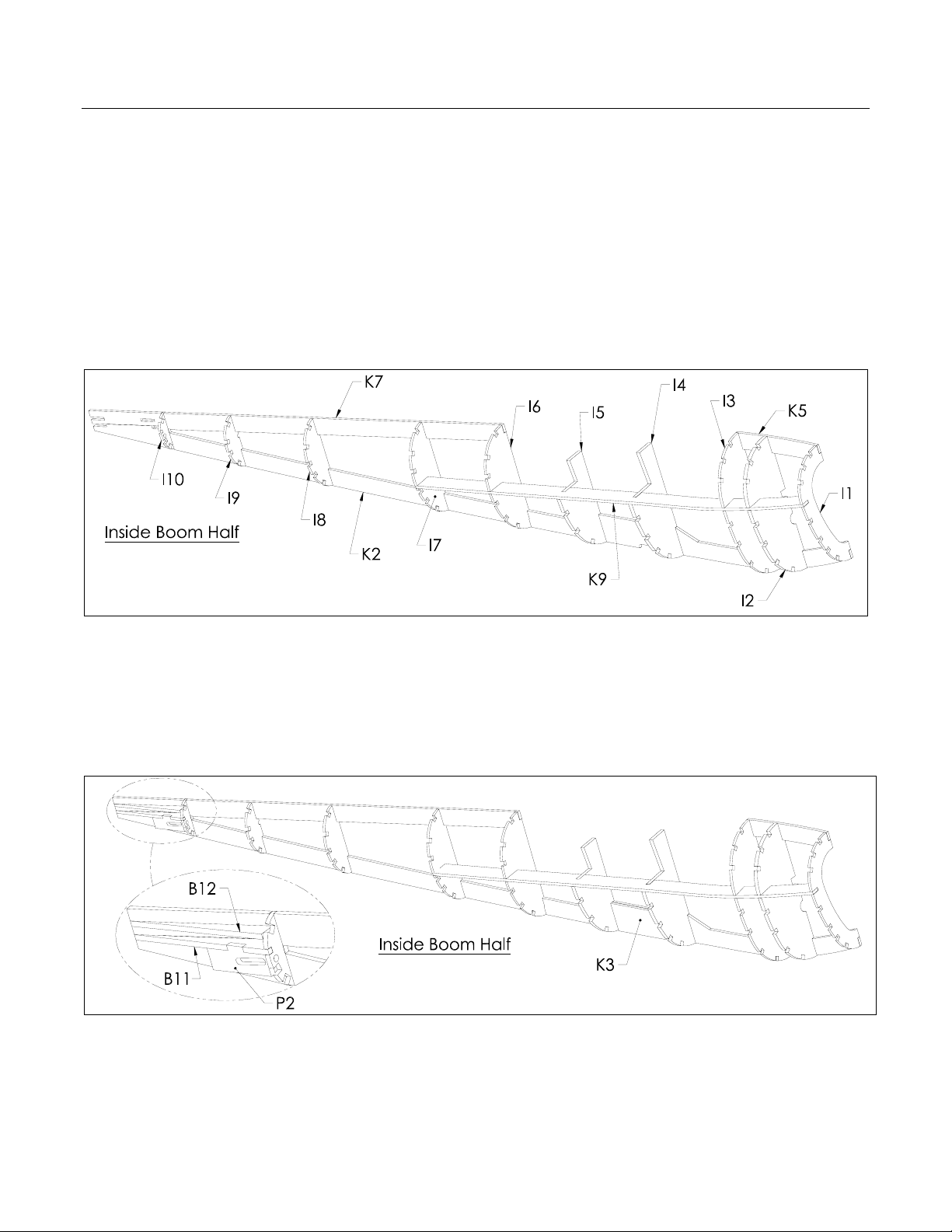
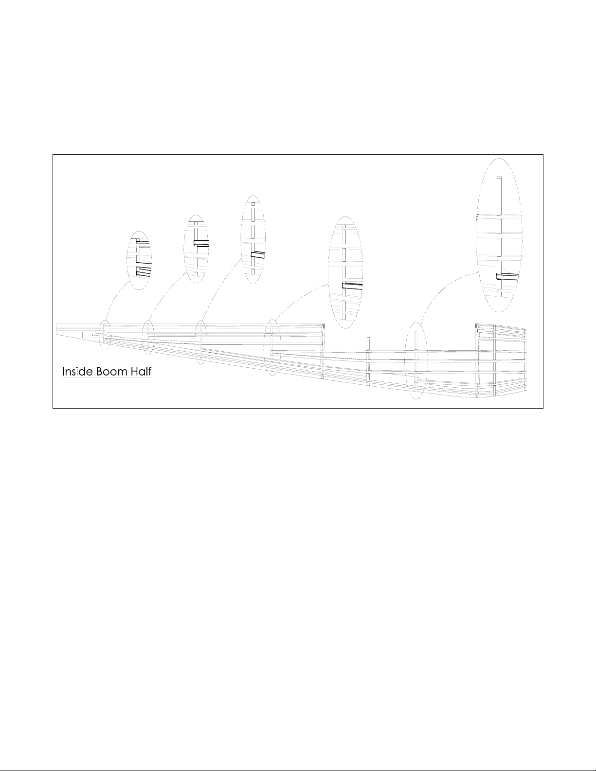
Inside Boom Half
Pin boom keels K2, K5, and K7 over one of the Inside Boom Halves shown on the plans and glue
adjacent edges.
Glue the boom formers I1, I2, I4, I7, I8, I9, and I10 to K2, K5, and K7 making sure they are
perpendicular to the building surface. Be sure to orient each of the boom formers so that the
notches that accept K9 are in a line as you site down the boom.
Install, but DO NOT glue the boom formers I3, I5, and I6.
Glue K9 into the notches of each of the boom formers I1, I2, I3, I4, I5, I6, and I7. Note that K9 orients
I3, I5, and I6 at proper angles that interface the wing. Finish by gluing I3, I5, and I6 to K2, K5, and K7.
Figure 4
Glue B11 and B12 into the notches of K2, K7, and I10.
Glue pushrod exit P2 to B11 and O10.
Glue K3 to K2, I4, and I5. K3 supports the landing gear.
Figure 5
© Copyright 2004 Molt Models. All rights reserved. 7 of 44
Molt Models P-38 Building Instructions Rev A
Glue 3/32” SQ. Balsa Stringers to the boom formers as shown in Figure 6 and the plans. Figure 6
illustrates important areas of the boom where stringers end.
At this point the Inside Boom Half is complete and can be unpinned from the building board. Do
not be concerned if the boom half is a bit warped when it is removed from the building board, this
will be corrected when the boom halves are glued together.
Figure 6
© Copyright 2004 Molt Models. All rights reserved. 8 of 44
Molt Models P-38 Building Instructions Rev A
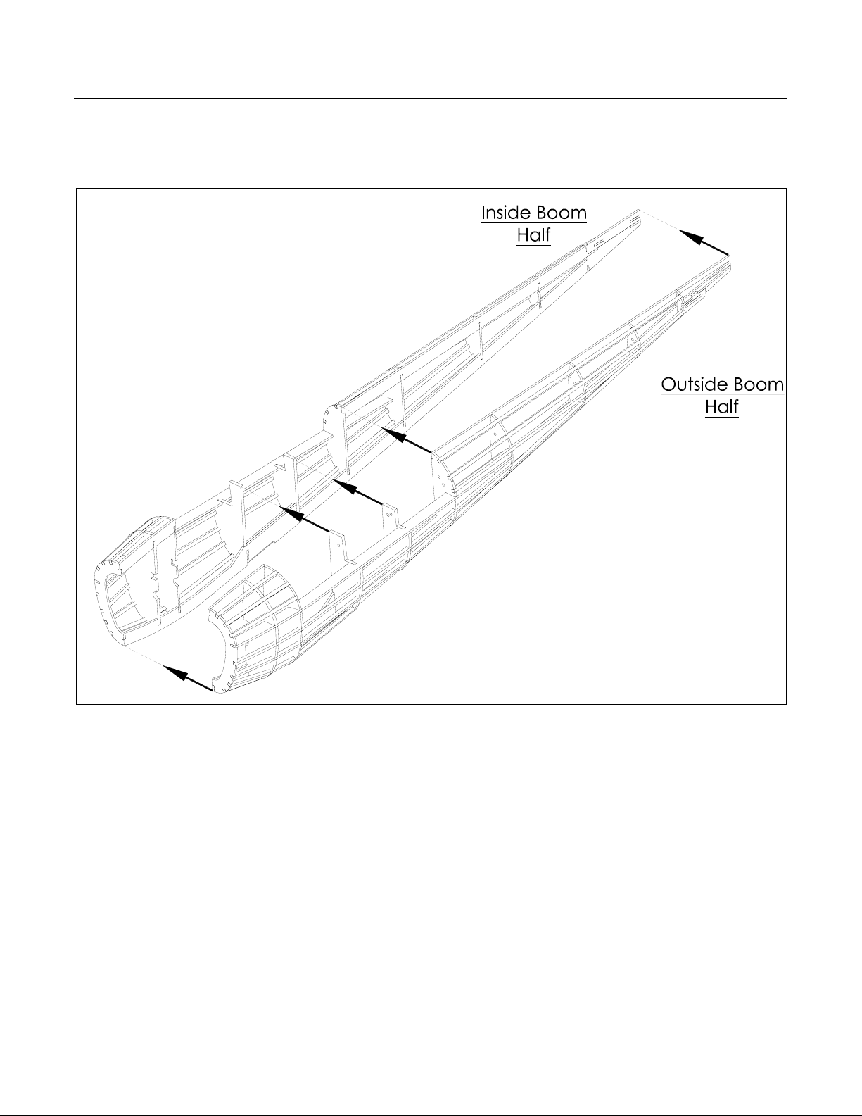
Boom Halves Joined
Glue the outside boom and inside boom halves together. Take care to insure the mating formers
I3/O3, I4/O4, I5/O5, I6/O6 are aligned and flush with each other. Be sure to glue each of the
mating formers and keels. A longer, more precise tip on your CA glue bottle can help here.
Figure 7
© Copyright 2004 Molt Models. All rights reserved. 9 of 44
Molt Models P-38 Building Instructions Rev A
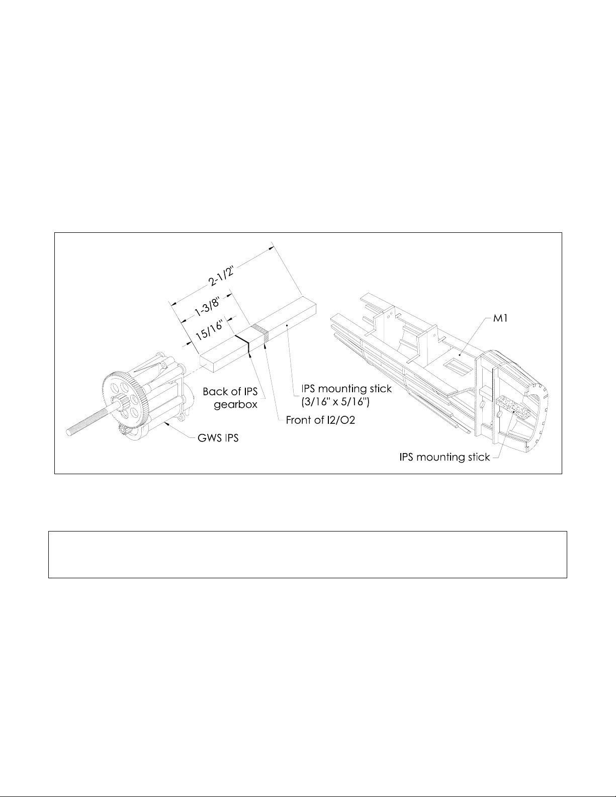
Find the 3/16” x 5/16” IPS mounting stick in the kit and cut it to the length shown in Figure 8.
Using a pencil, place marks on the mounting stick as shown in Figure 8. Make sure the GW S IPS
gearbox will slide over the mounting stick as far as it will go before gluing it to the boom. The back
of the gearbox should end up very close to the lin e d r awn at 15/16”.
Remove the GWS IPS gearbox from the mounting stick and slide the mounting stick into the
rectangular holes in I2/O2 and I3/O3. The mounting stick should slide all the w ay in until the line
drawn at 1-3/8” reaches the front of I2/O2. Glue the mounting stick to I2/O2 and I3/O3, be sure to
flood the joints with thin CA to assure a good bond.
Glue servo mount M1 to K8, K9, and I3/O3 as shown in Figure 8. Sand the boom to eliminate uneven
rough wood surfaces and excess dried glue. At this point the boom is complete.
Figure 8
At this point, one of the booms is complete. Build the other boom by starting at the
beginning of the Boom Construction section of this manual. Note that this boom will
be a mirror image of the previously constructed boom.
© Copyright 2004 Molt Models. All rights reserved. 10 of 44

Molt Models P-38 Building Instructions Rev A
Boom Covers
Pin C8 and C9 over the “Left Boom Cover” shown on the plans. Make sure C8 and C9 are
perpendicular to the building surface.
Glue C1, C2, C3, C4, and C5 to C8 and C9 as illustrated in Figure 9.
Glue the to p 3/32” SQ. Balsa Stringer, C6 and C7 to C1 through C5. Be sure to dry fit C6 and C7
before you begin gluing by pinning them to C1 through C5, starting at C5 and working your way
forward. When you are satisfied with the fit of C6 and C7 glue them to C1 throug h C5. There will be
some excess C6 and C7 material that protrudes out from C1, trim this off flush with C1 when the glue
is dry.
Glue the remaining 3/32” SQ. Balsa Stringers to C1 through C5, C6 and C7. The stringer that
interfaces with C7 will have to be cut at an angle to have a good fit.
Unpin the boom cover and finish cutting the small sections of balsa that retain the airfoil shaped
bottom of C8 and C9.
Build the “Right Boom Cover” shown on the plans in the same manner used to construct the “Left
Boom Cover”. Sand the boom covers to eliminate uneven rough wood surfaces and excess dried
glue. At this point the boom covers a re complete.
Figure 9
© Copyright 2004 Molt Models. All rights reserved. 11 of 44
Molt Models P-38 Building Instructions Rev A
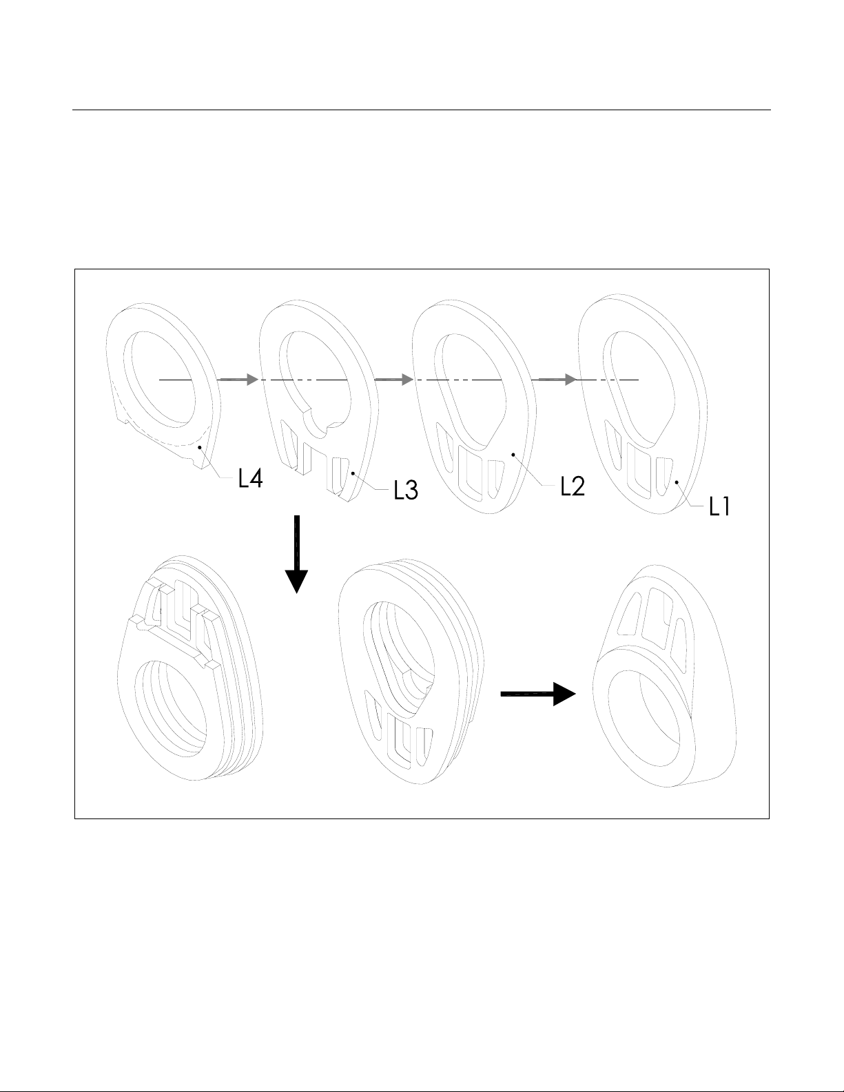
Boom Cowlings
Glue L1, L2, L3, and L4 together as shown in Figure 10 with wood glue.
Sand the lamination of L1, L2, L3, and L4 to the final shape shown in Figure 10. The engraved dashed
line on L4 is a guide to aid in the sanding process.
Build an identical boom cowling from the additional set of L1, L2, L3, and L4 formers. At this point the
boom cowlings are complete.
Figure 10
© Copyright 2004 Molt Models. All rights reserved. 12 of 44
Molt Models P-38 Building Instructions Rev A
Build Section #2 – Fuselage Construction
The fuselage of the P-38 is constructed in two halves and then glued together to form the complete
fuselage. The fuselage building section of the plans refer to “Right Fuselage Half” and “Left Fuselage
Half”.
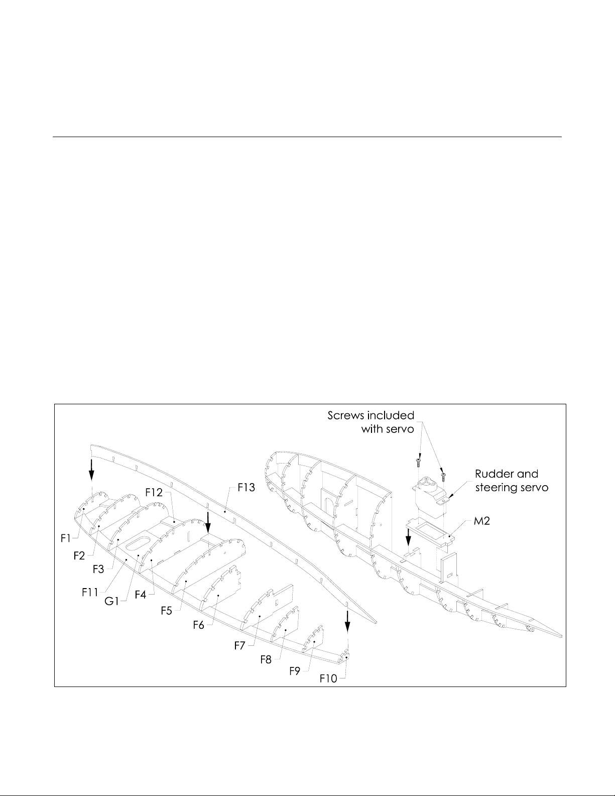
Fuselage Halves
Pin fuselage keels F11, F12, and nose gear former G1 over the “Left Fuselage Half” (“Right Fuselage
Half” when working through this section for the second time) shown on the plans and glue adjacent
edges.
Glue fuselage formers F1, F2, F3, F4, F6, F7, F8, F9, and F10 to F11, F12, and G1 making sure they are
perpendicular to the building surface. Be sure to orient each of the fuselage formers so that the
notches that accept F13 are in a line as you site down the fuselage.
Install, but DO NOT glue the fuse former F5.
Glue F13 into the notches of each of the fuselage formers F1 through F10. Note that F13 orients F5 at
the proper angle to interface the wing. Finish by gluing F5 to F11, F12, and F13.
Glue servo mount M2 to F6, and F7 as shown in Figure 11. Note M2 is NOT installed in the “Right
Fuselage Half”.
Install the rudder and steering servo wi th the mounting screws included with the servo. Note the
orientation shown in Figure 11. The servo arm should be trimmed/modified to an “L” shape; this
matches the arm shown in Figure 11.
Figure 11
© Copyright 2004 Molt Models. All rights reserved. 13 of 44
Molt Models P-38 Building Instructions Rev A
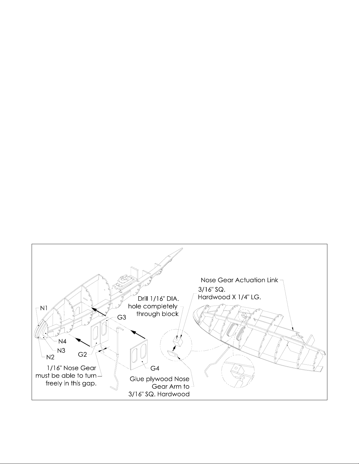
Glue G2 and G3 to G1, F3, F4, and F11. When G2 and G3 are installed there should be a 1/16” gap
between them, which receives the nose gear assembly. Be sure to fit the 1/16” nose gear wire into
the gap so it that rotates without excessive friction.
Glue N1, N2, N3, and N4 to F1 and each other with wood glue.
Construct the nose gear as shown in “Nose Gear Bending Template and Assembly” section of the
plans. Insert the nose gear assembly i nto the 1/16” gap between G2 and G3. The plastic 1/8" O.D.
plastic tubing sections will ride on the top and bottom of G1, G2, and G3.
Glue G4 to G2, G3, F3, and F4 to encapsulate the nose gear assembly. Be careful not to get glue on
any part of the nose gear assembly. The nose gear is now a permanent part of the left fuselage half
and should rotate freely. Note the nose gear assembly will be tilted at an angle while it is pinned to
the building surface.
Drill a 1/16” DIA. hole through the ce nter of the 3/16” SQ. X 1/4" LG. Hardwood block and glue the
plywood nose gear arm to it as shown in Figure 12.
Construct the Nose Gear Actuation Link that co n n e cts the nose g e a r as sembly to th e r u d der and
steering servo as shown in “Nose Gear Actuation Link” section of the plans.
Insert the Nose Gear Actuation Link into the hole and slot of fuselage formers F3 and F4.
Slide the Hardwood block/plywood nose gear Arm assembly onto the “Z” B end of the Nose Gear
Actuation Link as shown in Figure 12. Next, slide the Hardwood block/plywood Nose Gear Arm
assembly onto the nose gear assembly so that it lines up flush with the end of the 1/16” wire. This is
illustrated in Figure 12 and should be glued with 5-minute epoxy to ensure a strong bond. Once the
stringers are installed it will be difficult to gain access to this area of the fuselage again.
Figure 12
© Copyright 2004 Molt Models. All rights reserved. 14 of 44

Molt Models P-38 Building Instructions Rev A
Glue 3/32” SQ. Balsa Stringers to the fuselage formers as shown in Figure 13 and the plans. Figure 13
illustrates important areas of the fuselage where stringers end.
At this point the left fuselage half is complete and can be unpinned from the building board. Do
not be concerned if the fuselage half is a bit warped when it is removed from the building board,
this will be corrected when the boom halves are glued together.
Build the right fuselage half by starting at the beginning of the Fuselage Halves section of this
manual and working from the “Right Fuselage Half” section of the plans. Note that the right
fuselage half will not include any of the provisions to mount the nose gear or rudder and steering
servo. Only the left fuselage half contains structure and hardware for the nose gear.
Figure 13
© Copyright 2004 Molt Models. All rights reserved. 15 of 44

Molt Models P-38 Building Instructions Rev A
Fuselage Halves Joined
Glue the left fuselage and right fuselages halves together. Take care to insure the mating formers F1
through F10 are aligned and flush with each other. Be sure to glue each of the mating formers and
keels. A longer, more precise tip on your CA glue bottle can help here.
Glue T1 through T10 to F13s, F10, and each other with wood glue.
Install the nose gear wheel. The nose gear wheel is held on with short section of 1/8” O.D. plastic
tubing cut to 1/8” LG. The plastic tubing is attached with thin CA glue to the nose gear wire, be
careful not to get any glue on the wheel. This is illustrated in Figure 14. (Note, the Du-bro wheels
may have to be drilled out to fit the nose gear wire)
Install the Micro Connector to the servo arm in the location illustrated in Figure 14. Slide the Nose
Gear Actuation Link into the Micro Connector, center the nose gear and tighten the Micro
Connector screw to retain the Nose Gear Actuation Link.
Sand the nose and tail of the fuselage smooth to blend into the shape of the fuselage. Also, sand
the fuselage to eliminate uneven rough wood surfaces and excess dried glue. At this point the
fuselage is complete.
Figure 14
© Copyright 2004 Molt Models. All rights reserved. 16 of 44

Molt Models P-38 Building Instructions Rev A
Build Section #3 – Wing Construction
The wing of the P-38 is constructed in two halves and then glued together to form the complete wing.
Wing Halves
Create the laminated spars, S1 and S2 by gluing two S1’s and two S2’s together by using the “Spar
Lamination” section shown on the plans. Laminate these spars with wood glue or epoxy and pin
over the plans to make sure they remain straight and true.
Pin laminated S2, 3/32” SQ. Balsa, W11, and E1 over one of the wing halves shown on the plans and
glue adjacent edges.
Glue R2 through R15 to laminated S2, 3/32” SQ. Balsa, W11, and E1 making sure they are
perpendicular to the building surface. Note R2 has to be scored on the etched line with your
modeling knife to fit the shape shown on the plans. Flood the scored line of R2 with CA glue after it
is pinned to the shape shown on the plans.
Glue R1 to the laminate d S2, 3/32” SQ. Balsa, and E1 making sure it is tilted to the angle created with
the use of the “Rib R1 angle gauge” shown on the plans and illustrated in Figure 15.
Glue W12 and W13 to W11 and R15.
Figure 15
© Copyright 2004 Molt Models. All rights reserved. 17 of 44

Molt Models P-38 Building Instructions Rev A
Glue laminated S1, 3/32” SQ. Balsa, and LE to R1 through R15 and W11 where applicable.
Glue A9 to R13 and the bottom 3/32” SQ. Balsa.
Figure 16
© Copyright 2004 Molt Models. All rights reserved. 18 of 44

Molt Models P-38 Building Instructions Rev A
Glue the two 3/32” SQ. Balsa to R1 through R15.
Glue A8 to the two 3/32” SQ. Balsa, R15, and R11.
Glue shear webs W1 through W10 to laminated Spars S1, S2, and adjacent ribs. Note that the grain
of these shear webs is always perpendicular to the building surface. The orientation of each shear
web can be seen in Figure 17.
Ailerons
Pin E2 over one of the ailerons shown on plans.
Glue and pin A1 through A5 to E2 making sure they are perpendicular to the building surface.
Glue A7 to A1 through A5.
Glue A6 to E2 and E7. The gap between A6 and A3 is intentional and allows a place for the aileron
control horns to be glued.
Figure 17
Build the other wing half and aileron by starting at the beginning of the Wing Halves section of this
manual and working from the plans.
© Copyright 2004 Molt Models. All rights reserved. 19 of 44

Molt Models P-38 Building Instructions Rev A
Wing Halves Joined
With one wing half fixed flat to the buildi ng surface, glue on the other wing half with the tip elevated
to the dimension shown in Figure 18. Join the two wing halves with Epoxy.
Sand the leading edge of the wing blending it into the shape of the wing/airfoil. Also, sand the wing
to eliminate uneven rough wood surfaces and e x cess dried glue.
Figure 18
Build Section #4 – Horizontal/Vertical Stabilizer, Elevator, and Rudder Construction
Build the horizontal stabilizer, elevator, vertical stabilizers, and rudders per the “Tail Components”
section of the plans.
Build Section #5 – Control Installation
To maintain scale functionality, manage weight, and minimize the number of servos, the Molt Models
P-38 makes use of a creative control system. The rudder servo is mounted in the fuselage and is
required to operate the nose gear (if installed) as well as both rudders. The elevator servo is mounted in
the left boom, and the aileron servo is mounted in the right boom.
Each component containing a hole with an engra ved letter next to it designates a place where a
control tube will be routed through. The letter “r” designates a hole where a rudder c ontrol tube will
pass through, and similarly, “a” for aileron, and “e” for elevator. In most areas where a control tube
passes through you should glue the tubing to the component. However, there are areas where the
tubing SHOULD NOT be glued to a component and those areas are marked with an exclamation point
enclosed in a triangle. See Figure 19.
© Copyright 2004 Molt Models. All rights reserved. 20 of 44

Molt Models P-38 Building Instructions Rev A
Letters engraved are typical for each of the components
that require tubing to be routed through them.
Designates an area where tubing should not be glued to a component.
Figure 19
© Copyright 2004 Molt Models. All rights reserved. 21 of 44

Molt Models P-38 Building Instructions Rev A
Wing
Install the flexible plastic tubing in the wing as shown in Figure 20. The tubes for the rudder will hang
loose towards the trailing edge of the wing for the time being.
1/4"
1/4"
Flexible yellow plastic tubing
for aileron actuation cable
1/16"
Flexible yellow plastic tubing
for rudder actuation cable
1/16"
1/4"
Figure 20
1/4"
Flexible yellow plastic tubing
for aileron actuation cable
Flexible yellow plastic tubing
for rudder actuation cable
© Copyright 2004 Molt Models. All rights reserved. 22 of 44

Molt Models P-38 Building Instructions Rev A
Left Boom
Install the flexible plastic tubing in the left boom as shown in Figure 21.
Install the elevator servo with the mounting screws included with the servo. Note the orientation
shown in Figure 21. The servo arm should be trimmed/modified to the shape matching the arm
shown in Figure 21.
Install the Micro Connector to the servo arm as illus trated in Figure 21.
Flexible plastic tubing
for elevator actuation wire
7/16"
1/8"
Flexible yellow plastic tubing
for rudder actuation cable
Figure 21
Flexible yellow plastic tubing
for rudder actuation cable
© Copyright 2004 Molt Models. All rights reserved. 23 of 44

Molt Models P-38 Building Instructions Rev A
Right Boom
Install the flexible plastic tubing in the ri ght boom as shown in Figure 22. Note that there isn’t a
control tube for the elevator in this boom.
Install the aileron servo with the mounting screws included with the servo. Note the orientation
shown in Figure 22. The servo arm should be trimmed/modified to the shape matching the arm
shown in Figure 22.
Install the Micro Connector to the servo arm as illus trated in Figure 22.
Flexible yellow plastic tubing
for rudder actuation cable
7/16"
Flexible yellow plastic tubing
for rudder actuation cable
Figure 22
© Copyright 2004 Molt Models. All rights reserved. 24 of 44

Molt Models P-38 Building Instructions Rev A
Build Section #6 – Covering
Covering the P-38 is easy, but it is important to examine the next few steps so that covering is left out of
critical areas that interface each other. Before covering any of your P-38 Lightning, I recommend
taking a look forward to Build Section #7 - Assembly and Finishing. It is helpful to test fit the wing,
booms, boom covers, fuselage, tail, and all control surfaces as opposed to waiting to see if they fit after
covering. If necessary, parts should be sanded to achieve a proper fit. When you are comfortable with
the fit of the major parts, return to Build Section #6 – Covering, and proceed through the manual.
Wing
Cover the entire wing except for the section between ribs R6 and R7, and the section between both
R2’s. Also, DO NOT cover the leading and trailing edge between these ribs. This is illustrated in Figure
23 and shown by bold lines. These areas interf ace the booms and fuselage.
Completely cover each of the ailerons. DO NOT be concerned about hinging the control surfaces
at this point.
R7
R6
R2
R2
R6
R7
Figure 23
© Copyright 2004 Molt Models. All rights reserved. 25 of 44

Molt Models P-38 Building Instructions Rev A
Fuselage and Tail
Cover the entire fuselage except for the section illustrated in Figure 24 and shown by bold lines. This
area interfaces the wing.
Cover the entire horizontal stabilizer/elevator and vertical stabilizer/rudder except for the section
illustrated in Figure 24 and shown by bold lines. These areas interface the boom. DO NOT be
concerned about hinging the control surfaces at this point.
Figure 24
© Copyright 2004 Molt Models. All rights reserved. 26 of 44

Molt Models P-38 Building Instructions Rev A
Booms
Cover the entire boom except for the section between B11 and B12 (on both sides of the boom)
and the other areas illustrated in Figure 25 and shown by bold lines. These areas interface the
horizontal stab and wing.
Completely cover the top of each of the boom covers.
Figure 25
© Copyright 2004 Molt Models. All rights reserved. 27 of 44

Molt Models P-38 Building Instructions Rev A
Building Section #7 – Assembly and Finishing
Assembling the P-38 is easy, but it is important to examine the next few steps so critical areas that
interface each other are done properly. In this building section my preference is CA glue, but feel free
to use slower drying epoxy if you want more time to align the adjoining pieces.
Boom and Wing
Slide the boom into the wing noting that bo th of the spars in the wing are positioned ahead of the
boom formers. You’ll have to do this while Inserting the tube for the rudder that hangs loose towards
the trailing edge of the wing through the hole in former O5.
The boom is fully interlocked into the wing when the tops of the boom formers are aligned with or
slightly above the top of the wing spars. Be sure the bottom of the wing ribs are aligned on top of
the boom keels K8 and K9 as well.
When you’re sure things are fitting properly, soak every connecting surface of the wing and boom
with CA glue. This includes the leading edge, trailing edge, and spars of the wing to the their
adjacent boom formers as shown in Figure 26.
Repeat th e p r evious ste p s to glue the op p o s ite boom to the wing.
Glue
Glue
Glue
Figure 26
© Copyright 2004 Molt Models. All rights reserved. 28 of 44

Molt Models P-38 Building Instructions Rev A
Vertical Stabilizers, Horizontal Stabilizer and Booms
Slide each of the vertical stabilizers over their respective booms making sure they are centered on
seam created by the joined boom halves. U se a fine tipped ink pen or marker to trace a line
around each of the vertical stabilizers on the boom. Remove the vertical stabilizers and get rid of
the covering contained in lines created on the boom. Now reinstall the vertical stabilizers making
sure they are centered on the boom, use some stickpins to help hold them in p lace while you add
the horizontal stabilizer. Make sure a wood-to-wood joint exists between the vertical stabilizers and
the booms.
Slide the horizontal stabilizer over the vertical stabilizers and into the receiving slots built into the
booms. You may need to trim the notches in the horizontal stabilizer to get it to fit properly over the
vertical stabilizers and receiving slots of the boom . Use a fine tipped ink pen or marker to trace a
line around the boom and vertical stabilizers on the horizontal stabilizer. Remove the horizontal
stabilizer and get rid of the covering contained in lines created on the horizontal stabilizer. Now
reinstall the horizontal stabilizer and use stickpins to hold it in place. Make sure a wood-to-wood joint
exists between the vertical stabilizers, booms, and horizontal stabilizer.
Glue the vertical stabilizers, and horizontal stabilizer to the booms making sure each of the vertical
stabilizers are perpendicular to the horizontal stabilizer as illustrated in Figure 27.
Figure 27
© Copyright 2004 Molt Models. All rights reserved. 29 of 44

Molt Models P-38 Building Instructions Rev A
Control Surface Horns
Glue the plywood control horns in the control surfaces as shown in Figure 28 noting orientation. The
plywood control horns for the elevator and each rudder are identical and should be inserted into
the slot until they are flush with the opposite side of the control surface.
Install the Micro Connectors in the ply wood control horns shown in Figure 28.
Left rudder
Right rudder
These surfaces
flush after
installation
Bottom left
of aileron
Bottom
of elevator
Bottom right
of aileron
Figure 28
© Copyright 2004 Molt Models. All rights reserved. 30 of 44

Molt Models P-38 Building Instructions Rev A
Control Surface Hinges and Actuation
On all of my parkflyers I have used 3/4" transparent tape, which is readily available in most major
discount stores. Some people don’t care for this control surface hinge technique, but I can honestly say
I’ve never had a hinge fail when you make sure the tape is pressed firmly onto the covering.
Tape the control surfaces to their proper locations making sure to leave a 1/32” to 1/16” gap on the
hinge side to allow for rotation as illustrated in Figure 29. Make sure that the ailerons fit into their
openings without rubbing on adjacent surfaces.
3/4" transparent tape
Figure 29
© Copyright 2004 Molt Models. All rights reserved. 31 of 44

Molt Models P-38 Building Instructions Rev A
Construct the elevator actuation rod as shown in “Elevator Actuation Rod” section of the plans.
Insert the “Z” Bend end of the Elevator Actuation Rod into the elevator control surface horn then
slide the elevator actuation rod into the plastic tubing installed in the boom as illustrated in Figure 30.
Be sure to continue to slide the elevator actuation rod through the micro connector in the elevator
servo and tighten the setscrew with the elevator lined up with the horizontal stabilizer.
Tape the elevator to its proper location making sure to leave a 1/3 2” to 1/16” gap on the hinge side
to allow for rotation as illustrated in Figure 30. Make sure that the elevator fits into its opening without
rubbing on adjacent surfaces.
Cut a 32.5” length of the 1/32” diameter flexible steel cable to actuate the ailerons. Begin
installation by sliding the previously cut cable through the Micro Connector installed in one of the
aileron horns and into the yellow plastic tubing exiting the wing. Continue to sli de the steel cable
through the tubing and through the Micro Connector installed on the aileron servo. Lastly, slide the
cable through the remainder of the yellow plastic tubing for aileron control which exits the opposite
bottom of the wing and through the Micro Connector on the opposite aileron horn. Center the
ailerons in their wi ng openings and tighten each of the 3 Micro Connector setscrews.
3/4" transparent tape
Figure 30
© Copyright 2004 Molt Models. All rights reserved. 32 of 44

Molt Models P-38 Building Instructions Rev A
Install a piece of 1/8” diameter X 1/2" long heat shrink tubing over the two separate yellow plastic
tubes in the boom and wing to create a continuous run of tubing. Make sure you trim the adjoining
plastic tubes so that a smooth continuous curve is created; otherwise you will have some unwanted
friction between the cable and the tubing. Heat the heat shrink tubing with a heat gun or your
covering iron to cre ate a tight fit over the yellow plastic tubing. Do this for each of the boom/wing
interfaces. This is illustrated in Figure 31
Cut a 43” length of the 1/32” diameter flexible steel cable to actuate the rudders. Begin installation
by sliding the previously cut cable through the Micro Connector installed in one of the rudder horns
and into the yellow plastic tubi ng exiting the boom. Continue to slide the steel cable through the
tubing and through the Micro Connector installed on the rud der/steering servo. Lastly, slide the
cable through the remainder of the yellow plastic tubing for rudder control which exits the opposite
boom and through the Micro Connector on the opposite rudder horn. Align the rudders with their
vertical stabilizers and tighten each of the 3 Micro Connector setscrews.
Flexible yellow plastic tubing
for rudder actuation cable
(boom portion)
Flexible yellow plastic tubing
for rudder actuation cable
(wing portion)
1/8" diameter X 1/2" long
heat shrink tubing
Figure 31
© Copyright 2004 Molt Models. All rights reserved. 33 of 44

Molt Models P-38 Building Instructions Rev A
Main Landing Gear and Boom Cowlings
Tape the boom cowlings to each boom as illustrated in Figure 32. A small piece of 3/4" transparent
tape on each side of the boom cowling is all that is required to attach it to the boom.
Construct a left and right main landing gear as shown in “Main Landing Gear Bending Template”
section of the plans.
Glue each the left and right main landing gear to their respective booms as illustrated in Figure 32.
Install the two main landing gear wheels. The main landing gear wheels are held on with a short
section of 1/8” O.D. Plastic Tubing cut to 1/8” LG. The plastic tubing is attached with thin CA glue to
the main landing gear wire, be careful not to get any glue on the wheel. This is illustrated in Figure
32. (Note, the Du-bro wheels may have to be drilled out to fit the main landing gear wire)
Figure 32
© Copyright 2004 Molt Models. All rights reserved. 34 of 44

Molt Models P-38 Building Instructions Rev A
Boom Scoops
Trim each of the vacuum formed boom scoops to approximately match what is illustrated in Figure
33.
Paint the boom scoops to your liking.
Vacuum formed
boom scoop
~3/16" (top and bottom)
Figure 33
© Copyright 2004 Molt Models. All rights reserved. 35 of 44

Molt Models P-38 Building Instructions Rev A
Glue the boom scoops to the inside and outside of the booms between formers I7/O7 and I8/O8,
and directly onto the covering with a light amount of 5-minute epoxy. This is illustrated in Figure 34.
Glue surface
(top and bottom)
Figure 34
© Copyright 2004 Molt Models. All rights reserved. 36 of 44

Molt Models P-38 Building Instructions Rev A
Boom Covers
Tape the boom covers to their Booms as illustrated in Figure 35.
Boom Cover
3/4" transparent tape
3/4" transparent tape
Figure 35
© Copyright 2004 Molt Models. All rights reserved. 37 of 44

Molt Models P-38 Building Instructions Rev A
Battery Tray
Glue both X2 components perpendicular to X1 in the orientation illustrated in Figure 36. These parts
create the battery tray.
Glue the batt e ry tray asse m b ly to ribs R2, and fuselage formers F5 with 5-minute epoxy.
Glue some Velcro to the battery tray and battery pack as illustrated in Figure 36 with 5-minute
epoxy.
Glue a magnet to the center ribs R1 as illustrated in Figure 36 with 5-minute epoxy. This magnet
serves as one half the canopy latch.
Hook component of Velcro
X1
X2
("bristly" side)
Loop component of Velcro
on battery ("fuzzy side)
X2
Magnet
1"
Figure 36
© Copyright 2004 Molt Models. All rights reserved. 38 of 44

Molt Models P-38 Building Instructions Rev A
Canopy
Trim the vacuum formed canopy to approximately match what is illustrated in Figure 37.
Vacuum formed
canopy
~1/8" (both sides)
Figure 37
© Copyright 2004 Molt Models. All rights reserved. 39 of 44

Molt Models P-38 Building Instructions Rev A
Install the canopy over the wing and fuselage adjusting where necessary to achieve a good fit.
From a piece of 1/16” balsa scrap and magnet, fabrica te the remaining half of the canopy latch as
illustrated in Figure 38. Make sure the magnet is oriented so that it is attracted to the magnet
installed in the fuselage. Adjust the 1/16” balsa scrap and magnet in the canopy to a depth that
creates a nice tight fit between the canopy and the wing. Glue these to the canopy with 5-minute
epoxy.
Remove the canopy and paint it to your liking.
Install a small piece of 3/4" tape on the front of the canopy as illustrated in Figure 38. This piece of
tape acts as a hinge allowing you to open the canopy to replace batteries.
3/4" transparent tape
Magnet
Figure 38
© Copyright 2004 Molt Models. All rights reserved. 40 of 44

Molt Models P-38 Building Instructions Rev A
Spinner
Modify the GWS IPS rubber spinner included with your IPS to match what is illustrated in Figure 39.
Trim the plastic vacuum formed spinner to match what is illustrated in Figure 39.
Figure 39
© Copyright 2004 Molt Models. All rights reserved. 41 of 44

Molt Models P-38 Building Instructions Rev A
Install the spinner alignment plate, and modified GWS IPS rubber spinner onto the prop shaft.
Using the sp inner alig n ment plate to s u p p ort the back o f the spinner, glue the spinner onto the
modified IPS rubber spinner with 5-minute epoxy as illustrated in Figure 40.
When the glue is dry, remove the spinner from the prop shaft. Next, remove and discard the spinner
alignment plate.
Install the propeller you wish to use for your model, and then reinstall the spinner onto the prop shaft.
You will have to tri m small sections of the spinner away to fit around the propeller. Do this for both
spinners.
1/32" aircraft ply spinner alignment p late
(remove and discard after glue is dry)
Note: Spinner is shown sectio ned to
help visualize the assembly.
Figure 40
Glue between
surfaces
© Copyright 2004 Molt Models. All rights reserved. 42 of 44

Molt Models P-38 Building Instructions Rev A
Wiring
Build the motor wiring harness as shown in Figure 41. The motors are wired in parallel.
Route the harness through each wing half and boom, then connect it to each of the GWS IPS’.
Find a place for the Electronic Speed Control (ESC), and receiver in the fuselage. Connect the ESC
connector, and all servo connectors to their appropriate receiver channel. Note, you will need a
12” servo wire extension for the elevator and aileron servo.
GWS IPS
GWS IPS
Battery
NEG
POS
ESC
NEG
POS
Receiver
Motor wiring schematic
NEG
Motor
POS
NEG
Motor
POS
ESC
Figure 41
© Copyright 2004 Molt Models. All rights reserved. 43 of 44

Molt Models P-38 Building Instructions Rev A
Final Flight Preparation
I recommend you set the amount of control surface throw to the following settings…
Ailerons: 3/8" either direction
Rudders: maximize in either direction without interfering with horizontal stabilizer
Elevator: 3/8" either direction
The battery is held to the battery tray with Velcro supplied with the kit.
With everything installed in your P-38 Lightning, be sure the plane balances at the point a 1/4" in
front of the main wing spar S2.
desired performance.
After your test flight, feel free to mo ve the balance point to get the
With proper balance you’re ready f or your first flight with the P-38 Lig htning. On the first flight, get
the P-38 Lightning high enough that you can let off the control sticks to see what it does without
risking a crash. The P-38 Lightning is a very forgiving model and depending on the equipment you
chose to finish it, you may have to trim it out as necessary. If you experience some adverse yaw
with your P-38 Lightning, I’ve found that it is quite useful to coordinate the turns by add ing some
rudder. This can be done manually, or by mixing some rudder output with the aileron channel on a
computer transmitter.
Enjoy your Molt Models P-38 Lightning!
© Copyright 2004 Molt Models. All rights reserved. 44 of 44
 Loading...