

Molpir CTS100FT, CTS100MT, CTS100ST, CTS100XT User Manual

User Manual
GPS&GPRS CONTAINER TRACKING
SYSTEM
CTS100 SERIES
11/18/2008
Version 2.1

Version 2.1
NU_CTS100_001_12112010_EN
1
I. BRIEF INTRODUCTION
Container Tracking System utilizes the GPS and GPRS functions in one unit. You can
monitor the container or the vehicle location and set the system remotely. In addition,
the unit will send event report if any trigger occurs.
The standard report sent by the unit includes the information: (1) unit’s ID, (2) status,
(3) time, (4) GPS’s latitude and longitude, (5) speed, (6) direction, (7) battery level,
(8)device’s status, (9) event number, and (10) report configuration parameters.
The reporting mode can be categorized as ‘normal’ mode, and ‘power saving’ mode. In
normal mode, the GPS will always be activated while moving, and it can be shut off the
GPS when stop (for power saving purpose). To enable the maximum power saving,
user can choose “power saving mode”. In this mode, the GPS will be activated only
when there is a report to send while moving. The report parameters can be set from the
PC setup program. CTS100 can be set to go in sleep mode (while not moving); the
system will cut the power of GPS module in order to save power. With build-in 3-D
acceleration sensor, CTS100 can select related reporting modes with respect to it is
moving or not.
The device has built-in 4 circular, 5 rectangular and 20 point Geo-fence; it will send the
report to the server if the Geo-fence event is triggered.
The UNIT must be initialized by PC setup program in order to make communication
with the remote server /call center. There are four main sections that allow users to
program the device, (1) User detail (Device ID, server IP, and port, GPRS APN….) (2)
Geo-fence (4 circular, 5 rectangular and 20 point Geo-fence) (3) Report (Time,
Distance, speed, Low battery …) (4)Trigger report(Tamper, Door)
When there is no GPRS service or the server close. The unit will send short message to
the preset number. The max number of SMS message (monthly usage) and the
monthly renew date can be set from the pc setup program or the remote setup
program. Only 1 SMS number can be set. The reports sent via the SMS will be out again
via GPRS after a valid GPRS connection is made.
CTS100 can be configured by the PC setup program or the Over-the-Air (OTA)
commands / or remote program. The unit can communicate with the server via UDP or
TCP protocol. The protocol can be selected from the PC-setup program or remote
server commands.
Flash memory for recording reports up to 900 reports. It can be read out from the PC
setup program via serial port.
Using built-in real time clock to identify the report time, when GPS signal is lost. Hence,
if the report is received with “LAST KNOWN” message, the time in the report will be the
real time clock, but the GPS position will be the last known valid GPS position.
Three LED indicate the status of the system:

Version 2.1
NU_CTS100_001_12112010_EN
2
Power indicator: When the unit power on, the led will flash 1time/3sec by green. If the
power has low status, the LED will change to red, and the red LED will keep on when
charging mode. Even battery charge finished, the power LED will change to green. If
tamper switch is triggered, the power indicator will flash twice continuously; if door
sensor is triggered, the power indicator will flash 5 times continuously
GPS indicator: LED is GREEN when the unit has acquired a valid GPS signal, and it will
flash when the unit is searching GPS signal.
GSM/GPRS indicator: Orange LED will flash when the device is connected to the server
with valid GPRS connection. It will stay continuously on when it is in GSM mode. It will
stay off if there is no GSM reception.
Note that the GSM/GPRS and GPS LED’s indication will not be valid until the system
goes to the working mode, normally 30 seconds after power on.
II. The main unit’s housing with Strong Magnetic Gives You Easy Instant Install
Placement!
Just like we put you in control on how and when your CTS100 reports to you with your
own online controls, we also put YOU in control of how you want your CTS100 installed
on any container or vehicle.
In addition, the unit has built-in door magnetic sensor, it used to detect the container
door status.
III. BASIC FUNCTIONS
FUNCTIONS APPLICATIONS
GPS
GPS receiver will output a complete position, velocity, and time
(PVT) solution in the NMEA Version 3.0 protocol.
GPRS, SMS
GPRS use standard TCP or UDP communicate protocol. If the GPRS
service is failed, the SMS mode will be turned on for emergency
use.
Button Power switch
PC-setup
Initialize the uni
t and program the device, including Network APN,
server IP address, user message, report control, and Geo-fence
setting, etc …
Note that Network APN and server IP details must be set before the
installation.
Standard Report
Automatic report for tracking purpose:
Fixed time report
Fixed distance report
Trigger report
History data store 900 reports can be saved in unit and read from server and pc-setup
Version 2.1
NU_CTS100_001_12112010_EN
3
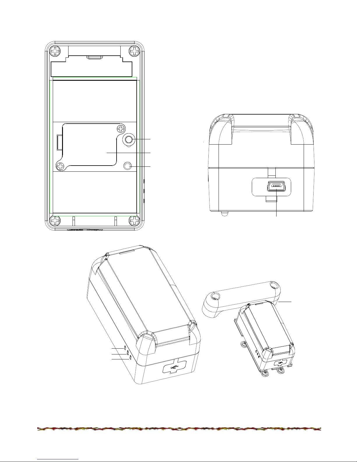
IV. PANEL INSTALLATION
Tamper switch
SIM card
Power switch
USB port
GSM/GPRS indicator: Orange
GPS status inticator: Green
Power indicator: Green/Red
Built
-
in door
magnetic
sensor
Version 2.1
NU_CTS100_001_12112010_EN
4
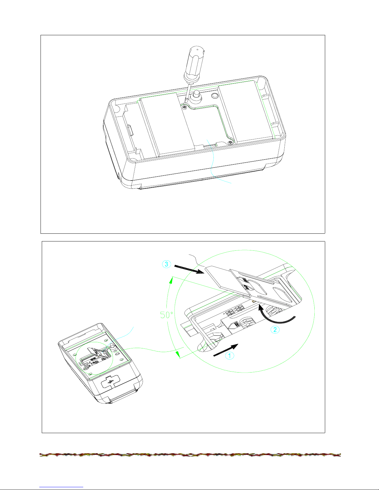
SIM card inserting guide:
SIM CARD LID
1. Using screwdriver to screw the screw, take out the SIM card lid.
SIM CARD
SIM card ped
estal lid
2. To jog SIM card pedestal lid (step 1), then opened it about 50° (step 2)
inseting SIM card (step 3)
Version 2.1
NU_CTS100_001_12112010_EN
5
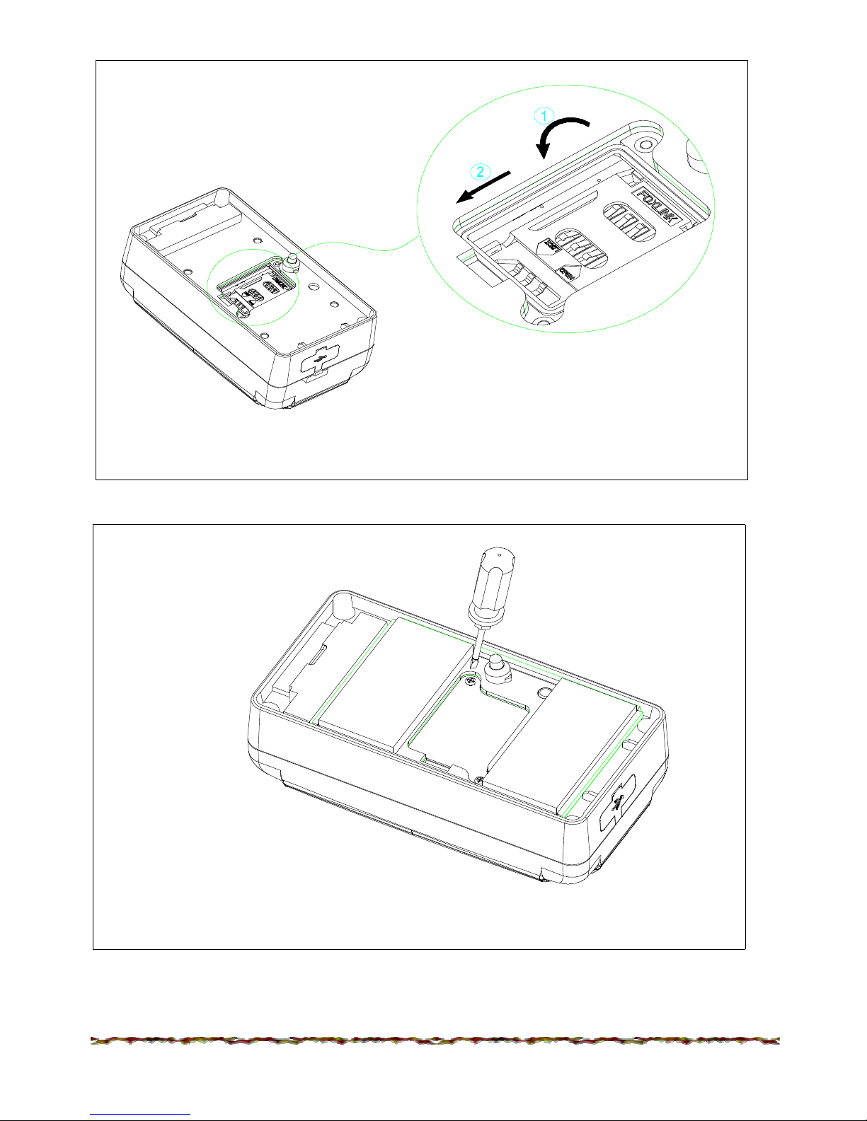
3. To set the lip of SIM card pedestal smoothly (step 1), roll it back to the
original place (step 2).
4. To cover the SIM card
lip, and tighten the screw.
Version 2.1
NU_CTS100_001_12112010_EN
6
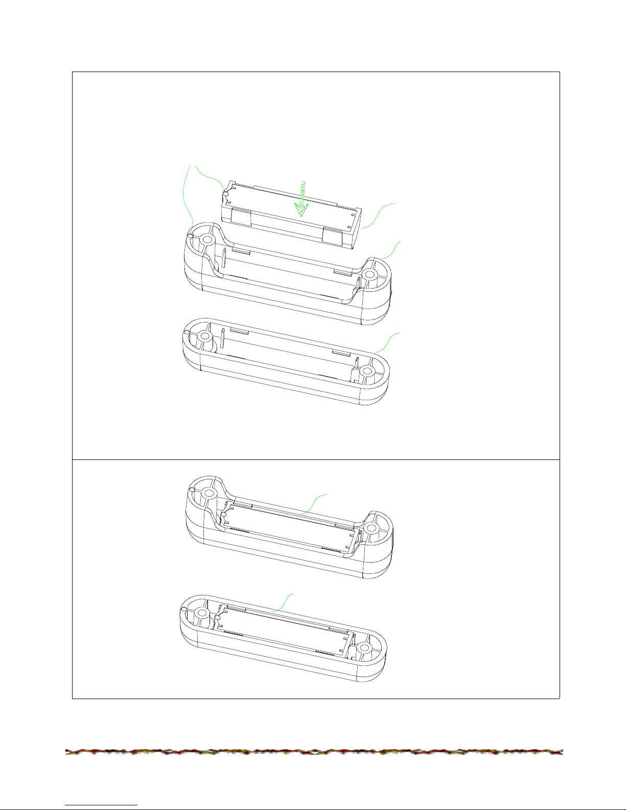
CTS100 magnetic stick installation guide
a)
Press the magnetic core into magnetic stick case. (To choose case A
or B base
on needed height)
b) Done
Door magnet B
Door magnet A
the two holes lap over
the same direction
press
Magnetic core
magnetic
stick case B
magnetic
stick case A
 Loading...