

Molnar SM450 Installation Manual
SM450 FOUR POST HOIST
5 Tonne Electro-Hydraulic Four Post Hoist
Installation Manual
Updated 14/12/2018

Page 2 of 19 Molnar 4 Post Hoist SM450
Contents
Installation Instructions Page 3-16
Installer Checklist Page 17
24V Transformer Wiring Detail Page 18
Single & three Phase Wiring Diagram Page 19
Please read this manual before you get started.
You must read and understand the precautions for safety purposes and any damages that may occur to your
property.
Address: 3 Graham Street
Export Park
South Australia 5950
Ph: +61 (08) 8234 3611
Fax: +61 (08) 8234 4322
Email: sales@molnarhoists.com.au
Web: www.molnarhoists.com.au
Specifications/images subject to change without prior notice, Images and sketches are for illustration purposes only.
Before commencing
operation inspect
system components,
control, emergency
stop and safety
equipment for
condition and correct
Page 3 of 19 Molnar 4 Post Hoist SM450
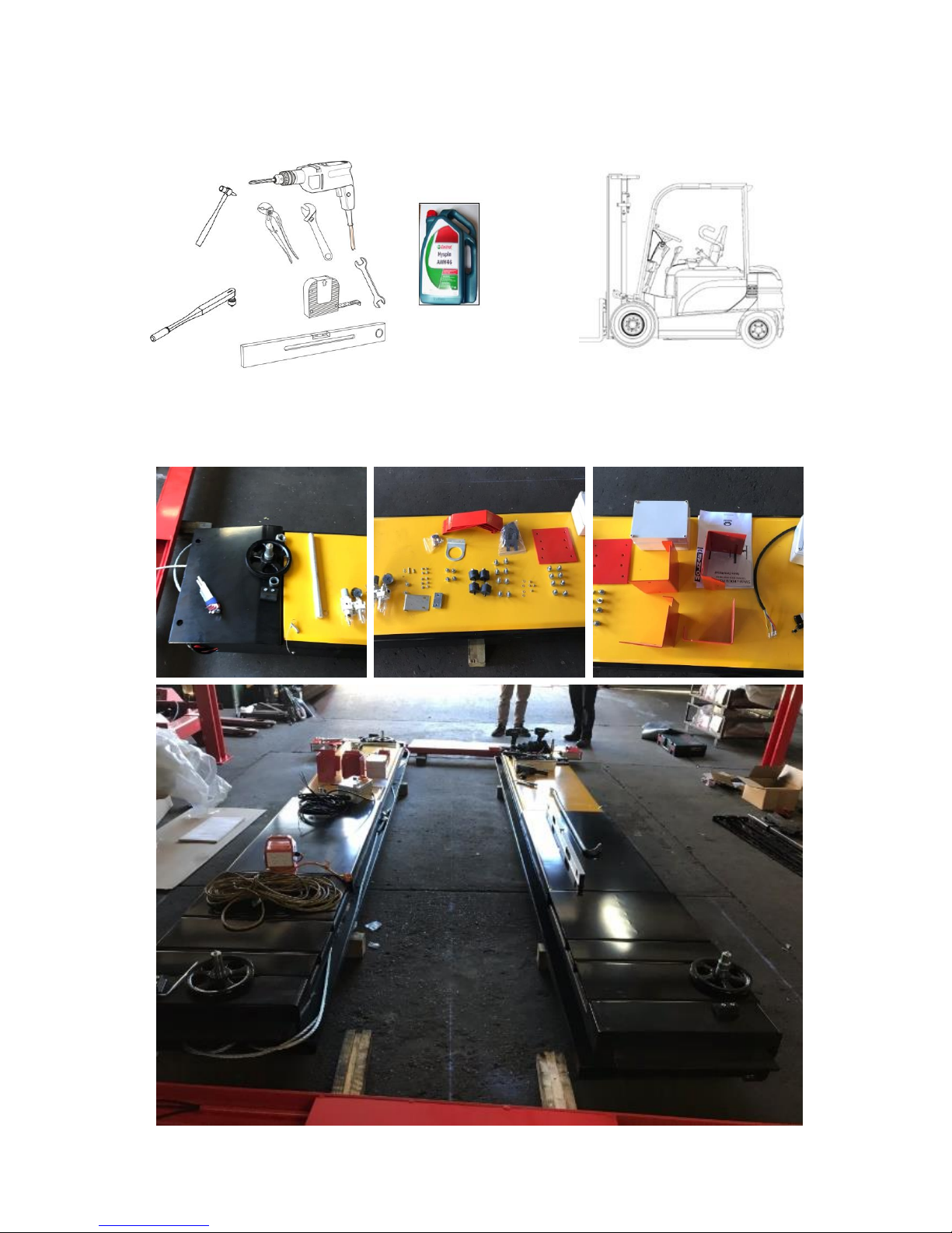
Tools Required:
Place all the components as shown to check supplied parts.
46 Weight AWH
Hydraulic Oil
10L
Page 4 of 19 Molnar 4 Post Hoist SM450
TRANSPORTATION AND INSTALLATION
Preparation for installation
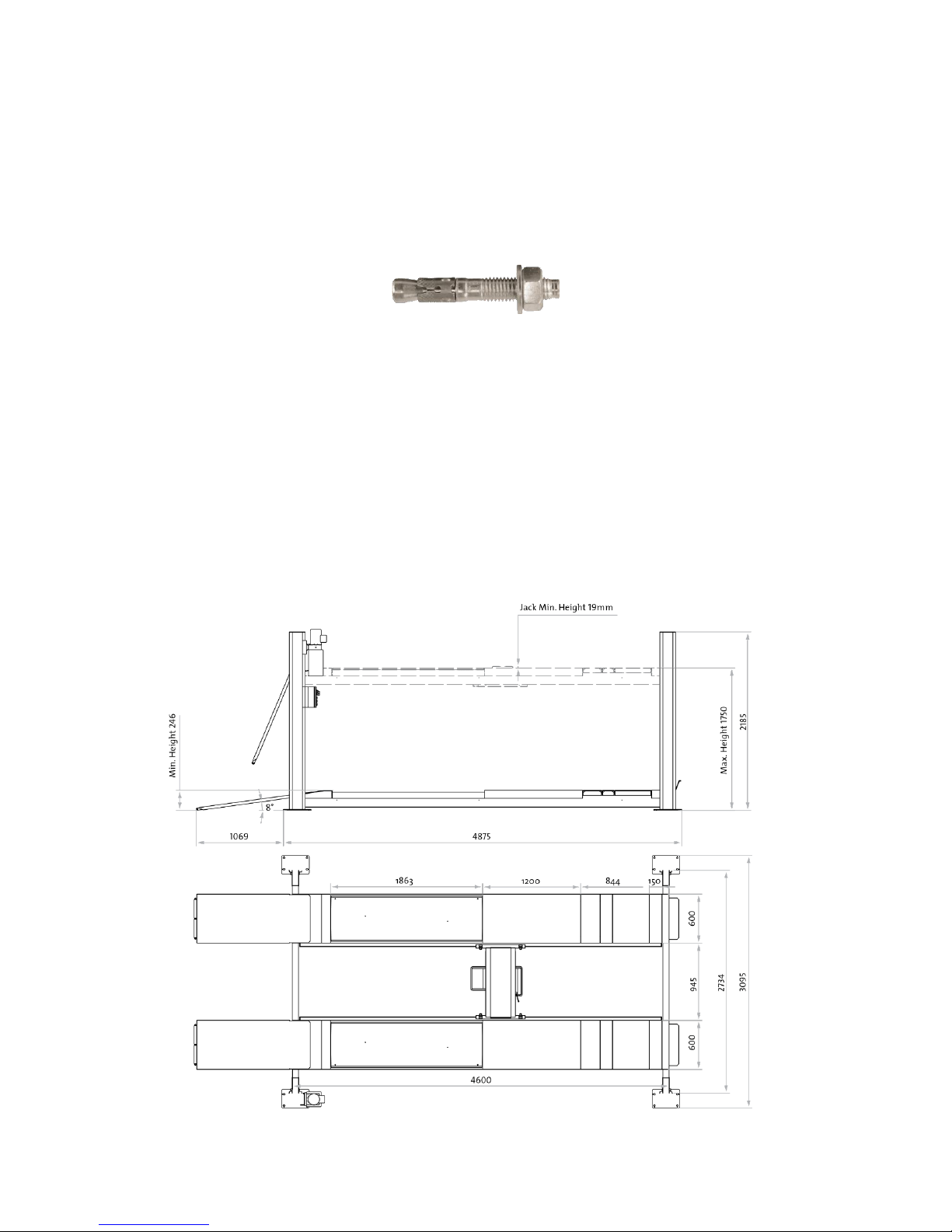
The hoist shall be installed on hard and flat floor made with reinforced concrete at 32MPa grade
with the thickness of 100mm minimum. The anchor bolt shall be M16 x 140mm tru-bolt and requires
16 anchor bolts.
Iccons Part No TB16140
Generally, this machine will be installed on the following conditions:
1) Supply voltage: 0.9 - 1.1 nominal supply voltage
2) Source frequency: 0.99 - 1.01 nominal frequency
3) Ambient temperature: 50C - 400C
4) Altitude: shall be at altitudes up to 1000m above mean sea level
5) Relative humidity: not exceed 50% at 40C
6) Atmosphere: Free from excessive dust, acid fume, corrosive gases and salt.
7) Avoid exposing to direct sunlight or heat rays which can change the environmental
temperature.
8) Avoid exposing to abnormal vibration.
9) Electrical equipment shall withstand the effects of transportation and storage temperature
within a range of -25°C to 55°C and for short periods not exceeding 24 hours at up to +70°C.
Page 5 of 19 Molnar 4 Post Hoist SM450
Installation Process
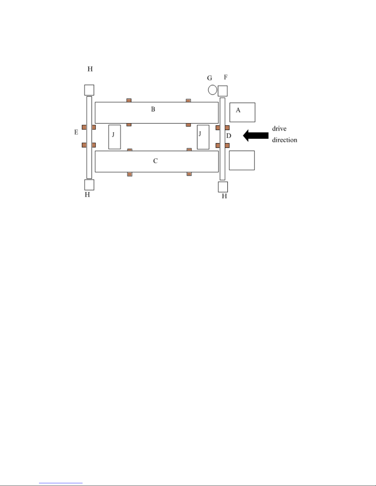
Layout Reference Diagram
A - Run up ramps
B - Control platform
C - Non-control platform
D - Transverse beam control end
E - Transverse beam non-control end
F - Control post
G - Power pack
H - Non-control post
J - Jacking beam
Placing hoist on the installation location using timber under the platforms and transverse beams
1) Place the main parts on the appropriate position in reference to the above layout diagram.
Page 6 of 19 Molnar 4 Post Hoist SM450
Assembling Transverse Beam for Platforms
1. Take the pins fixing guide block, pull out the pins and take out the transverse beam pulleys (4
positions)
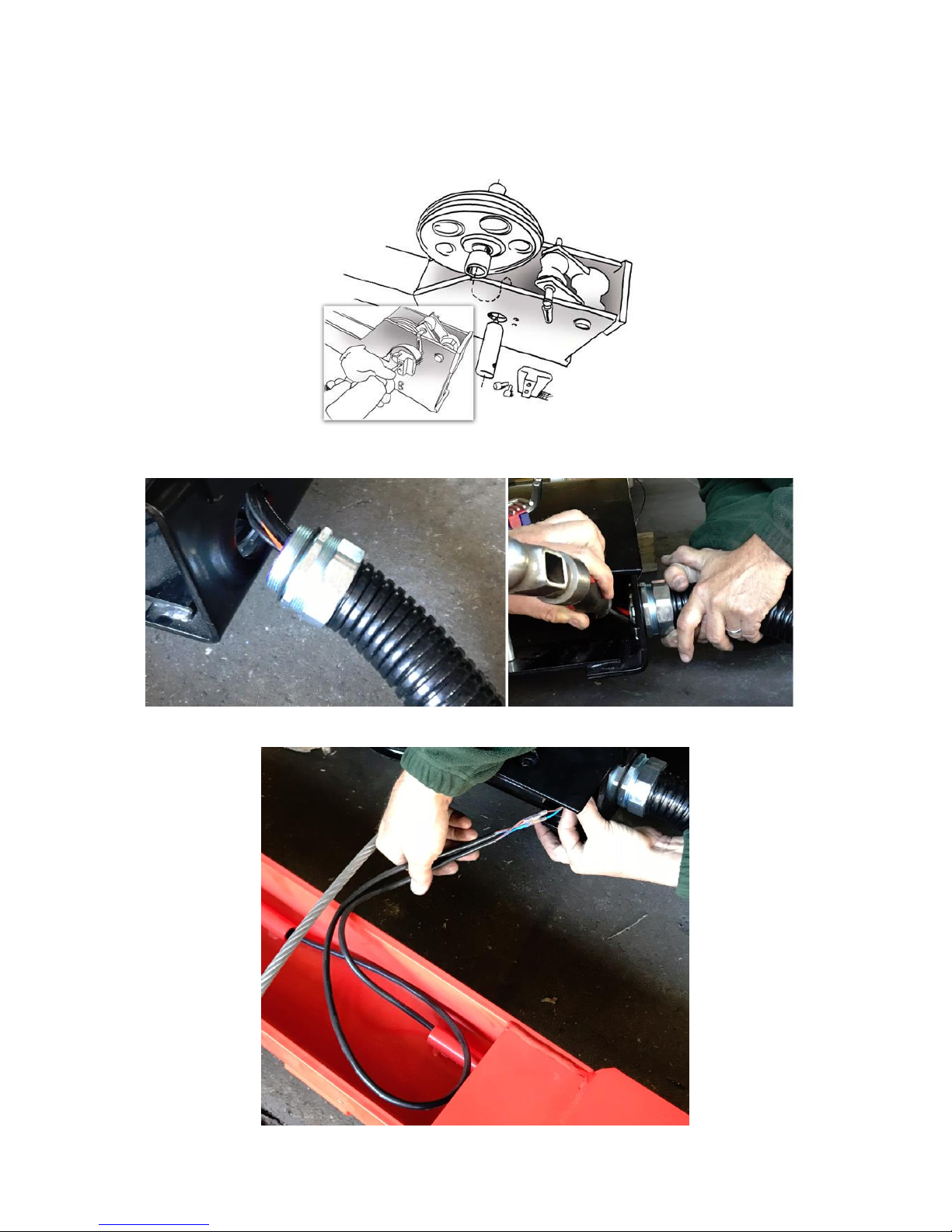
2. Remove the wood pieces inside the platform which are holding the cables inside. Cut the cable ties
and pull out the large black conduit and tighten the nut to the side of the platform.
3. Connect the lock cables into each end of the transverse beams.
 Loading...