

Molnar SM300 Installation Instructions Manual
T80123— Rev.:30/01-18
Always keep this document!
Must be read before using your equioment!
3T. Scissor lift
Installation instructions
(TRANSLATED VERSION)
T80123— Rev.:30/01-18 2
© Stenhøj A/S
Barrit Langgade 188-190
DK-7150 Barrit
Tel.: + 45 76 82 13 30
Fax.: + 45 76 82 13 31
E-mail: info@autopstenhoj.com
Internet.: www.autopstenhoj.com

T80123— Rev.:30/01-18 3
These instructions indicate step by step how you ensure a trouble-free installation and a satisfactory operation. It
is there of vital importance that you take the necessary time and care in order to ensure that the installation tolerances are not exceeded, otherwise the lift will not function effectively and you will not benefit fully from your
purchase of the lift.
NB: If these installation instructions are not followed strictly, the lift is not covered by warranty.
Information for construction engineer or architect:
Information for fitter:
8 expansion bolts used for the installation of the lift are included in the delivery.
NB: Drawing power when using other expansion bolts must be 25,2 KN per bolt.
NB: Note this arrow The lift will throughout these instructions be shown from the drive-on direction.
Model Quality of concretEN206-1: Depth
3T. Scissor lift C25/30 (Fcyl = 25 N/mm² / Fcube = 30 N/mm²)
(B25 = 25 N/mm²)
150mm. (HILTI HSA)

T80123— Rev.:30/01-18 4
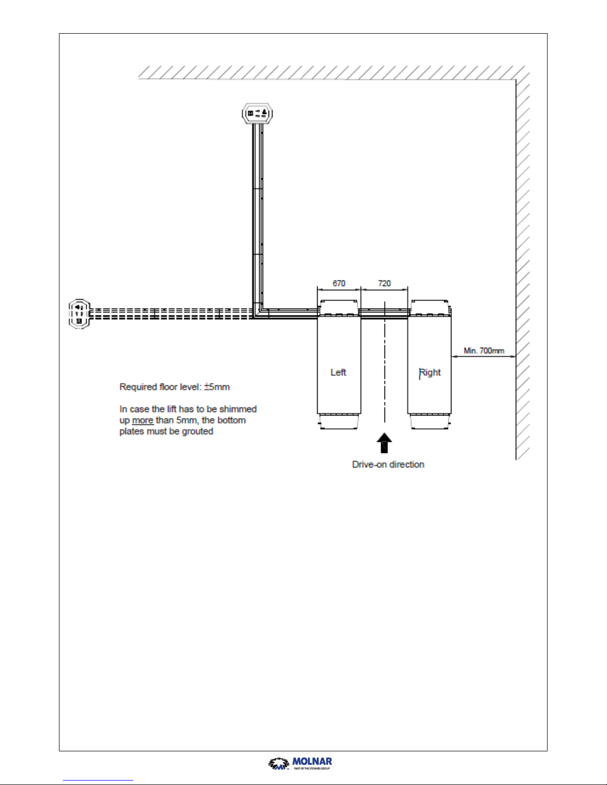
IMPORTANT: Check that installation site is in accordance with the following points:
Indoor and protected against penetrating water.
The dimensions of the installation site are as shown on picture 1.
Note: The requirements of the local authorities concerning installation of lifts must always be respected.
(Rules valid in Scandinavia: distance to walls: min. 0.7 m, distance between lifts and other machines: min.
1.1 m).
As standard the multi-purpose upright can be placed in front and/or left-right. Mark off according to the dimensions shown.
Upright is connected to mains via a switch according to local regulations and only by an authorized electrician. The installation must be connected to earth and protected by fuses:
• for 3 x 230 V-50 Hz, fuse 16A, neutral is not to be used (recommended cable section 2.5 mm²).
• for 3 x 400 V-50 Hz, fuse 16A, neutral must be used (recommended cable section 2.5 mm²).
T80123— Rev.:30/01-18 5

T80123— Rev.:30/01-18 6
2. Check that all tools shown, or corresponding ones, are available.
Provide approx. 9 l hydraulic oil according to specifications in the operation and maintenance instructions.
Check that contents of packing are complete, i.e. comprise 2 scissor members, drive-on ramps and locks, a
multi-purpose upright, a set of cable rails, a box with accessories and a CD or bag with miscellaneous technical documentation.
3. Take out the scissor members and place these exactly according to the marking off on fig. 1, i.e. both mem-
bers are placed where the left scissor member is going to be.
NOTE: Beware that hoses/cables turn forwards according to the drive-in direction.
4. Avoid in the following steps to damage these hoses/cables and place the right scissor member with a di-
stance of 785 mm to the left member (bottom plates).
 Loading...