

Page 1

MRS19201 Rev C 2014-06-25
Molift Rail System
EN - Handbook
Page 2

2
Molift Rail System / www.molift.com
Page 3

3
Molift Rail System / www.molift.com
English Manual
Content
Molift Rail System (MRS) – Introduction..................4
General...........................................................................4
1 How to use this handbook......................................5
2 Installation criteria – Principles...............................6
2.1 Site survey – Design criterias............................6
2.2 Lifting points.......................................................6
2.3 Mounting Molift Rail system............................7
2.4 Point loads.........................................................8
3 System Overview.......................................................9
3.1 Single rail system...............................................10
3.1.1 Ceiling mounted Straight rail system......11
3.1.2 Ceiling mounted Curve rail system.........13
3.1.3 Wall mounted Straight rail system..........14
3.2 Traverse rail system...........................................15
3.2.1 Ceiling mounted traverse system............16
3.2.2 Wall mounted traverse system................18
3.3 Combination of rail systems...........................20
3.3.1 Switch systems...........................................21
3.3.2 Climbing systems......................................23
4. Component Overview...........................................26
4.1 Attachment........................................................27
4.1.1 Ceiling Mounted System..........................27
4.1.2 Wall mounted System..............................29
4.2 Rails and Curves...............................................30
4.3 End Stops and End Caps................................32
4.4 Traverse Trolleys................................................33
4.5 Lift Motor Trolleys............................................35
4.6 Switches.............................................................36
4.7 Battery Charging..............................................37
4.8 Installation tools..............................................40
5. Design Conditions..................................................42
5.1 Lifting heights and lifting area.......................42
5.2 Design conditions – Attachments.................44
5.2.1 Ceiling mounted........................................44
5.2.2 Wall mounted............................................45
5.2.3 Attachments for cur ves...........................47
5.2.4 Side Support positioning.........................48
6 Installation methods...............................................54
7 Final Installation Procedure....................................56
7.1 Load test: Straight Rail System.......................56
7.2 Load test: Traverse Rail System......................56
7.3 Identification......................................................57
7.4 Installation Certification..................................57
8. System combinations – Case studies.................58
8.1 Single Rail system.............................................59
8.2 Traverse Rail system.........................................62
9. Installation instructions.........................................67
10. Maintenance.........................................................68
Service log...................................................................69
Checklist for installation of Molift Rail System......70
Periodic inspection for Molift Rail System..............71
Important
This User Manual contains important safety
instructions and information regarding the use of
the lifter and accessories.
In this manual the user is the person being lifted.
The assistant is the person operating the lifter.
Warning!
This symbol indicates important
information related to safety.
Follow these instructions carefully.
Visit www.molift.net for download of documentation to ensure you have the latest version.
Revision table
Rev ision A . 2013-12- 0 9
First release
Revision B. 2014-02-18
Updated illustrations and miscellaneous
details. New front page.
Revision C. 2014-06-25
Removed IRC components and room-to-
room transfer Molift Air. Added boxed
traverese trolley.
Page 4

4
Molift Rail System / www.molift.com
Molift Rail System (MRS)
Introduction
Molift Overhead Systems consist of a rail system,
Molift Rails System (MRS) combined with the lift
motor choices Molift AIR or Molift Nomad which
give innovative and efficient solutions when it
comes to lifting needs for disabled persons.
Molift Overhead Systems are easy and safe to use
and can solve most lifting situations. The functional and user friendly design provides greater
access to the user and increases assistant and user
safety. Molift solution gives a highly flexible, innovative, cost effective and profitable investment.
This handbook provides support and guidance to
installation performance of Molift overhead lift
systems and contains important information about
the design criteria and installation solutions. It is
important to thoroughly understand the content
of the handbook.
Conditions of Performing Installation
Lift and transfer of a person will always pose
a certain risk and only certified personnel are
allowed to install the equipment and accessories
covered by this technical manual.
Only personnel authorized by Etac
can perform installation of the
Molift overhead system and issue
the installation certificate, all in
accordance with Etac’s installation
instructions and this handbook.
The lifter is not intended to be operated by the
person being lifted. If a hoist is to be used by a
disabled person living on their own, then some
form of communication device shall be installed
in the area of use of the hoist so that in the event
of an emergency the disabled person is able to
summon assistance. This may, for example, be
the fitting of an alarm system or the supply of a
conveniently placed telephone, etc.
General
Declaration of conformity
The Molift Rail System and related accessories described in this handbook are CE marked
in accordance with EU Council Directive 93/42/EEC concerning medical devices, class 1, and
is manufactured in conformity with standards IEC 60601-1, IEC 60601-1-2 and NS-EN ISO
10535:2006.
Components made by other manufacturers
We recommend only using Etac Molift components. Etac shall not be liable for faults or accidents
that can occur when using components made by other manufacturers.
System should consist of only original MRS components. If not Decalaration of
conformity is not valid and Etac is not responisble for warranty of the system
Page 5

5
Molift Rail System / www.molift.com
In order to design a lifting solution, create a specification, order the parts and install the overhead
systems You need following documents apart
from this Handbook:
- Molift Pricelist
- Molift Product catalogue
- Site survey
- Installation instructions
The Handbook is divided into nine main chapters.
Chapter 1 – Molift Rail System (MRS)
Introduction of Molift Rail System. General terms
and a description how to use this handbook.
Chapter 2 - Installation criteria – Principles
Description of the principles for installing a Molift
Rail System, Site survey process and how to handle
different constructions material in buildings.
Chapter 3 –System Overview
Overview of possible system configuration and
combinations of MRS.
Chapter 4 – Component Overview
This chapter describes the MRS products and
which components are available for different
design solutions.
Chapter 5 - Design Conditions
This chapter describes the design conditions, limitations and possibilities how to combine the MRS
products to create a sufficient and safe Molift
Overhead System.
Chapter 6 - Installation methods
This Chapter describes work flow and tools for
survey and installation process.
Chapter 7 - Final Installation Procedure
This Chapter describes procedure for the final testing and certification of installed rail system.
Chapter 8 - System combinations – Examples
This Chapter describes a few of the most common
design solutions of Molift Rail System. Shows combination possibilities, measurements and examples
of specifications.
Chapter 9 - Installation instructions
This Chapter describe list of available Specific
Installation Instructions for the various mounting
options for MRS.
Chapter 10 - Maintenance
This Chapter describes how to perform periodic
inspection, service and repair to the rail system.
1. How to use this handbook
Page 6

6
Molift Rail System / www.molift.com
2. Installation criteria – Principles
2.1 Site survey – Design criteria
A site survey is the first project input, and it is
of great importance that this is performed and
archived in a proper way. We recommend that all
points in our Site Survey template are considered,
and that existing on-site conditions are documented preferably with photos and drawings.
Depending of the size of a ceiling lift installation
project, it is also of importance to consider how to
organize logistics for a ceiling lift installation:
• When should the installation take place (in
larger building projects)?
• What floor is the installation to be done?
• How do we get the rails there? (Crane?
Elevator? Stairs?)
• How to install efficiently? Installations teams or
single workers?
• How to handle disposals (packaging materials)?
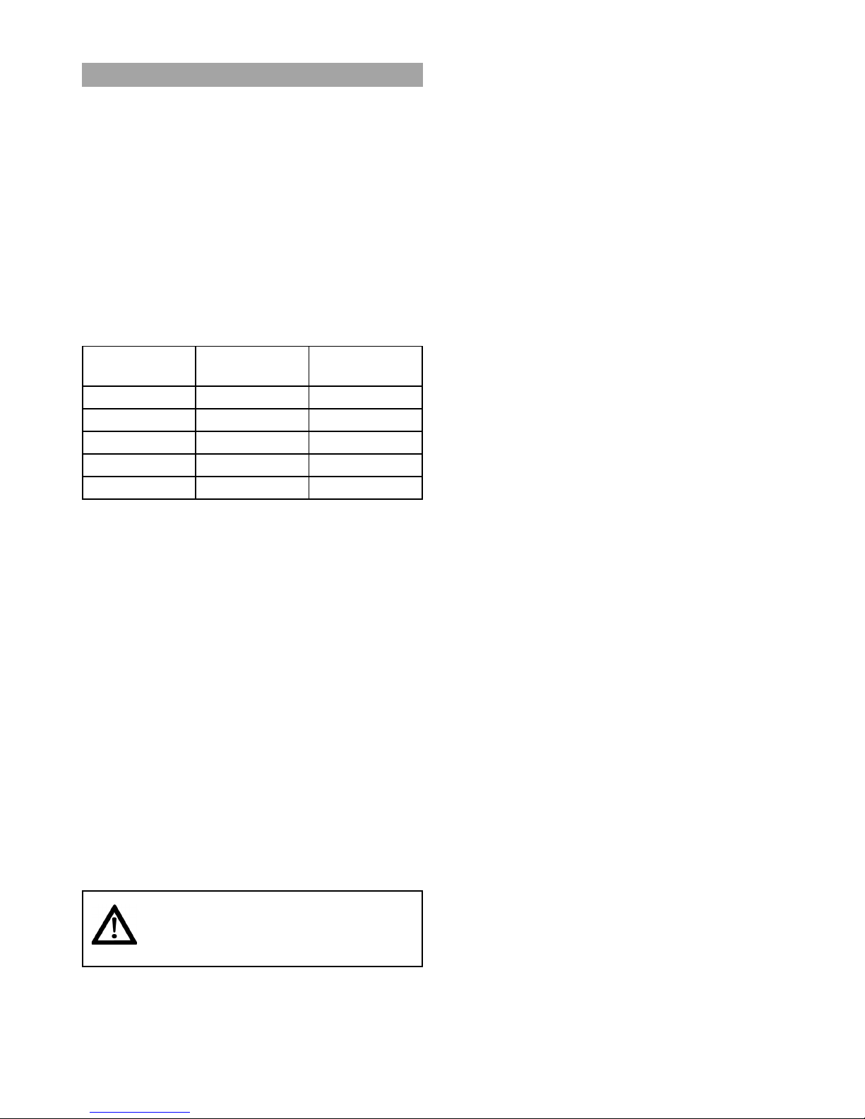
2.2 Lifting points
One important issue in the survey is to identify
and define lifting points and optimal placement of
the rail systems.
Figure: Furniture and lifitng points
100 cm
Page 7

7
Molift Rail System / www.molift.com
2.3 Mounting Molift Rail System
The way of mounting a ceiling lift system is based
on the specific materials and structural design on
each specific site.
Ceiling materials:
- Concrete; hollow core slabs or compact
layers
- Wood structures (requires reinforcements
between rafters)
- Light materials (LECA, Siporex etc)
Wall materials:
- Concrete
- Bricks
- Wood structure
- Light walls (Gyproc/plasterboards)
Upright supports:
- Upright supports are used where the exist-
ing structure or other installations does not
allow fixing in walls or ceiling.
Reinforcements to existing structues
- Reinforcements must be installed if the
existing building structure OR the materials
are too weak for the installation
Figure: Example of reinforcement of wood wall
structure with upright reinforcement between two
studs for mounting of wall bracket or wall rail.
Figure: Example of reinforcement of wood ceiling
structure with joist hangers and reinforcement
between joists.
Figure: Example of reinforcement of wood ceiling
structure with lying joist over joists.
Page 8
8
Molift Rail System / www.molift.com
2.4 Point loads
All systems should have minimum of two
anchoring (attachment) points.
One attachment point = one or more fixings
(expander bolts, chemical anchors etc.)
All attachment points of a ceiling lift system
should, according to prevailing standard EN-ISO
10535:2006, withstand a pullout force; the working load of the system installed times a safety
factor 1,5.
MRS attachment point Load Calculations:
• Molift Lift motors have 5 different weight
capacities within the range: 160 – 300 kg
Weight
capacity
Nomad Air
160 kg X
205 kg X X
230 kg X
255 kg X
300 kg X
• Standard ceiling lift system including any
straight rail or traverse system with 1 lift
motor.
• Estimated weight of equipment at pendant
support location for standard system =
approx. 30 kg
(includes: lift motor weight, rails, pendant,
traverse carrier, etc)
• Ultimate Point load for each support
attachment location is based upon the
maximum capacity of the lift motor +
estimated weight of the equipment at the
support attachment location times a safety
factor of 1,5
Example:
For a standard system with 200 kg motor:
200 kg = 200 kg – Safe Working Load
200 kg +30 kg = 230 kg – Working Load
230 kg x 1,5 = 345 kg – Ultimate Point
load
All fixings should always be tightened with torque specified by the
anchor/fixture manufacturer.
Page 9
9
Molift Rail System / www.molift.com
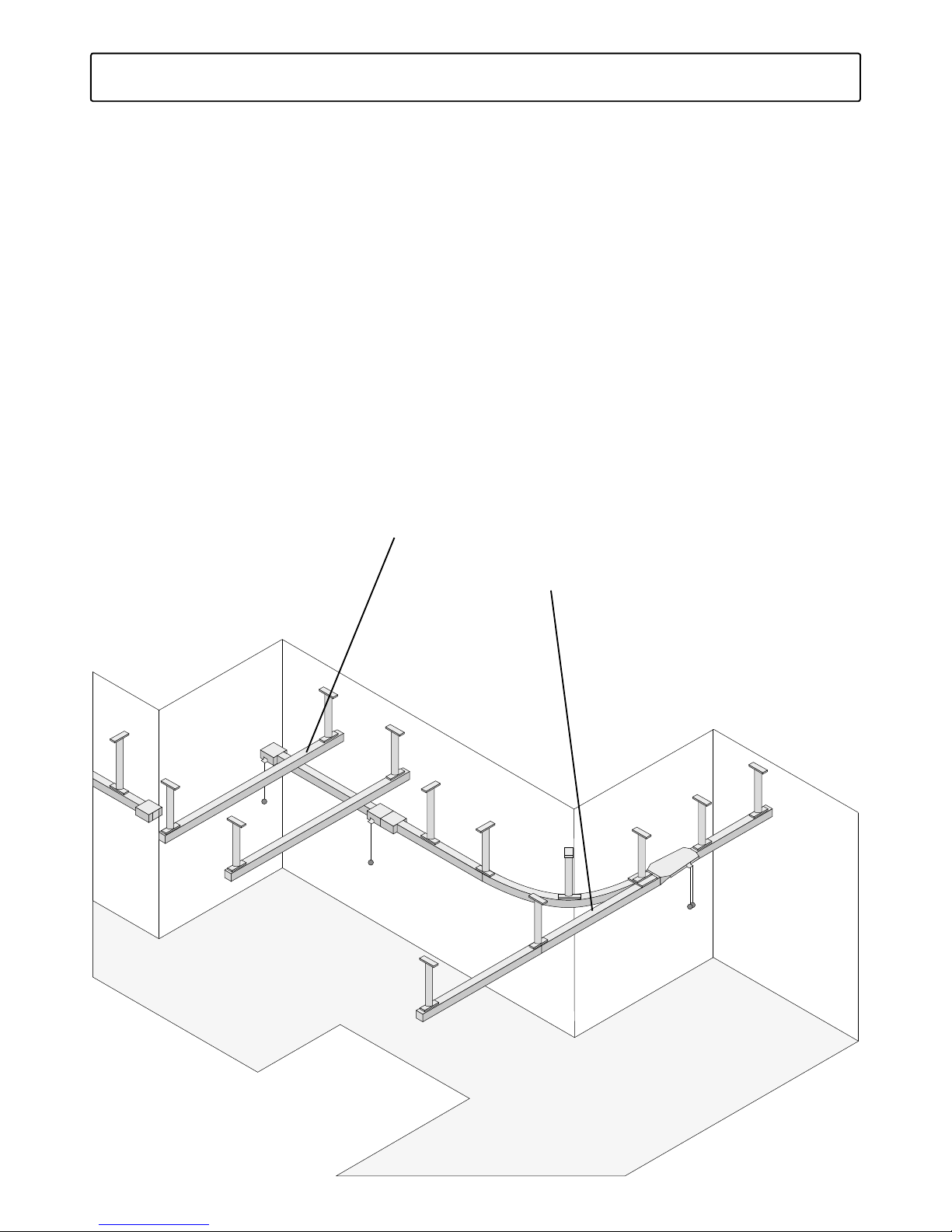
3. System Overview
Molift Rail System (MRS) is a ceiling hoist system built in three different main configurations:
1. Single rail system
2. Traverse rail system
3. Combination of single rail and traverse systems
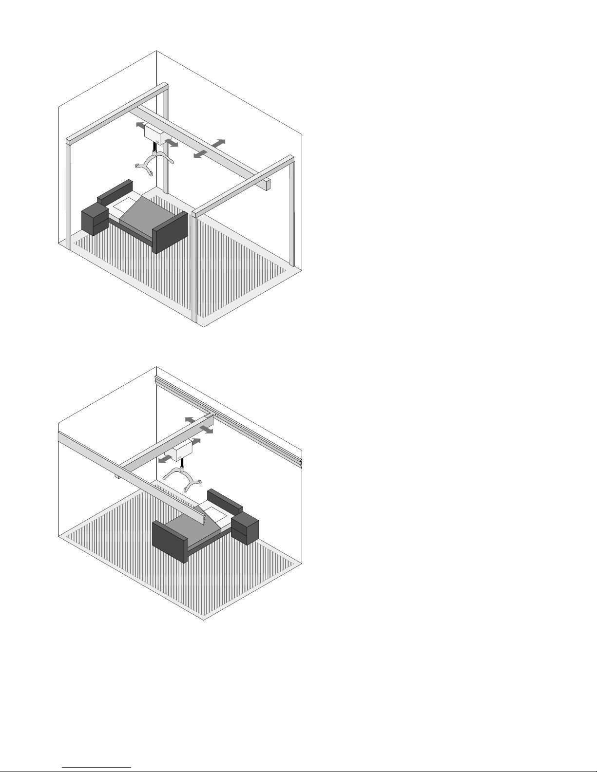
The area below the track system is defined as the lifting area. The area below a straight rail system is
limited to the rail, while a traverse system gives lifting area below the area covered by the traversing
secondary rail.
Single rail system
Traverse rail system
Page 10
10
Molift Rail System / www.molift.com
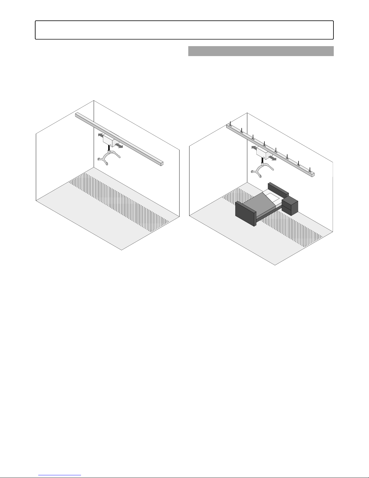
3.1 Single rail system
In a straight rail system the lift motor can be
moved horizontally along the rail path. By combining MRS curves and rails it is possible to create
single rail systems with expanded lifting area. The
curve rail system can only be mounted to ceiling
and does not allow wall mounting.
Lifting Area = Hatched area on floor under lifter.
3.1.1 Ceiling mounted Straight rail system
Can be mounted in four different ways:
1. Directly to ceiling without brackets
2. Mounted to ceiling with brackets
3. Suspended from the ceiling with telescopic
brackets
4. Suspended from the ceiling with threaded
rods
Figure: Ceiling mounted direct to ceiling without
brackets
Page 11

11
Molift Rail System / www.molift.com
Figure: Ceiling mounted with open ceiling using
40mm brackets
Figure: Ceiling mounted with telescopic brackets
Page 12

12
Molift Rail System / www.molift.com
Figure: Ceiling mounted with threaded rods
Page 13

13
Molift Rail System / www.molift.com
3.1.2 Ceiling mounted Curve rail system
By combining MRS curves and rails it is possible
to create single rail systems with expanded lifting
area. This solution does not allow free standing or
wall mounting. Can be mounted to ceiling only.
Figure: Ceiling mounted with telescope brackets
Figure: Ceiling mounted with open ceiling using
40 mm brackets.
Page 14

14
Molift Rail System / www.molift.com
3.1.3 Wall mounted Straight rail system
A wall mounted system is mounted on separate
wall brackets or on brackets connected to uprights
supported by the wall.
Figure: Wall mounted wall bracket
Figure: Wall mounted Wall brackets supported by
upright supports
Page 15
15
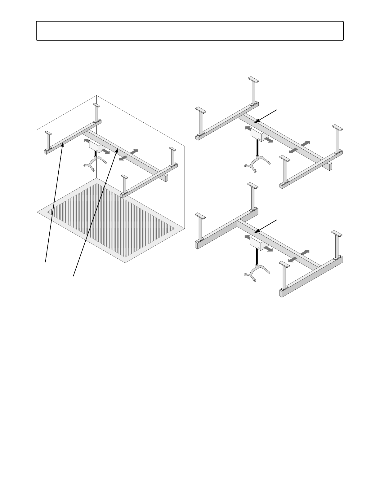
Molift Rail System / www.molift.com
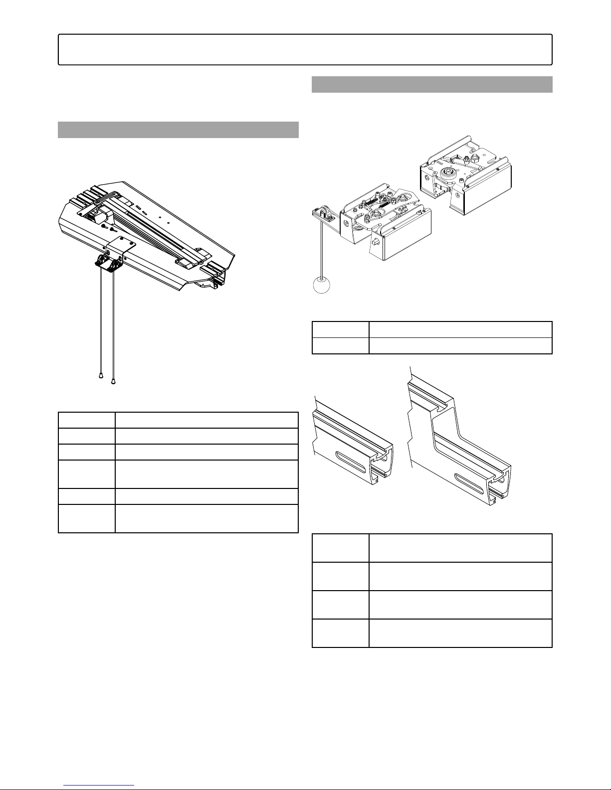
A traverse system is built up by two parallel
primary rails, a secondary rail connected to the
primary rails by a traverse trolley in each primary
rail. The lifting motor is connected in the secondary rail. This system allows full room coverage.
Primary rail
Secondary rail
3.2 Traverse System
Secondary Rail mounted
under Primary rails,
under trolley
Secondary Rail mounted
between Primary rails,
on top of trolley (Box-in)
Page 16

16
Molift Rail System / www.molift.com
3.2.1 Ceiling mounted traverse system
Ceiling mounted traverse rail system can be
mounted in different ways:
1. Directly in ceiling without brackets
2. Directly in ceiling with brackets
3. Suspended from the ceiling with telescopic
brackets
4. Suspended from the ceiling with threaded
rods
Figure: Ceiling mounted without brackets direct
to ceiling
Figure: Ceiling mounted with brackets with open
ceiling profile
Page 17

17
Molift Rail System / www.molift.com
Figure: Ceiling mounted telescopic brackets with
open ceiling profile
Figure: Ceiling mounted threaded rods with open
ceiling profile
Page 18

18
Molift Rail System / www.molift.com
3.2.2 Wall mounted traverse system
A wall mounted system is mounted on separate
wall brackets, wall mounted rails or on brackets
connected to uprights supported by the wall and
the floor.
1. Primary rails mounted on separate wall
brackets.
2. Primary rails mounted on brackets connected
to uprights supported by the wall and the
floor.
3. Primary rails mounted on wall rails.
Figure: Wall mounted rail with wall brackets
Page 19
19
Molift Rail System / www.molift.com
Figure: Wall mounted with wall brackets and
upright supports
Figure: Wall mounted rail direct to wall with wall
rail
Page 20

20
Molift Rail System / www.molift.com
MRS allows a great variation of possibilities when
combining traverse systems and single rail system.
Transfer between different systems/rooms and
locations can be solved in several ways with MRS
The simplest way is by extending the single rail
track through doorway.
The systems can also be combined with different
switches such as Rail switch and Traverse switch.
Climbing from one system to next is also an
option both with permanently mounted lift motor
Molift AIR and portable lift motor Molift Nomad.
3.3 Combination of rail systems
Page 21

21
Molift Rail System / www.molift.com
3.3.1 Switch systems
For Single rails, switching direction from straight
rail to curve etc. Manually controlled.
Figure: Rail switch
Traverse Switch – For transfer from secondary rail
in a traverse system into a straight rail or another
secondary rail in a traverse system. Manually
controlled.
Figure: Traverse system with switch to straight rail
Page 22

22
Molift Rail System / www.molift.com
Figure: Traverse system with switch in both ends.
Figure: Double traverse system connected with
switches.
Page 23
23
Molift Rail System / www.molift.com
3.3.2 Climbing systems
Molift Nomad is suitable for climbing (room to
room transfer) between two rails system
Figure: Room to Room transfer with Portable
motor Molift Nomad.
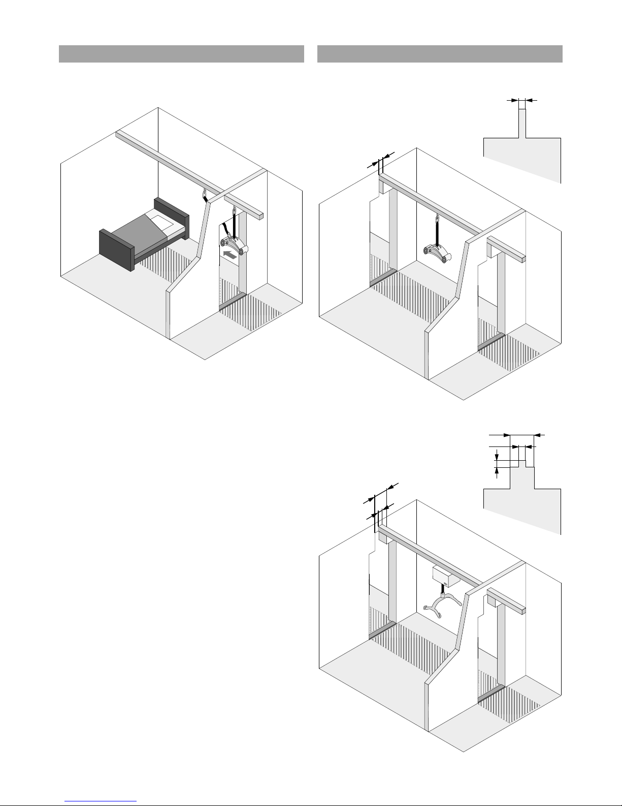
3.3.3 Hatch in door opening.
With a hatch in the dooropening, hoist can move
freely from room to room.
A
A=100mm
Figure: Hatch in door opening for Molift Nomad.
A
B=100mm
A=250mm
B
C= Rail Height (62/112/142mm)
Figure: Hatch in door opening for Molift Air.
Page 24
24
Molift Rail System / www.molift.com
3
5
6
2
1
4
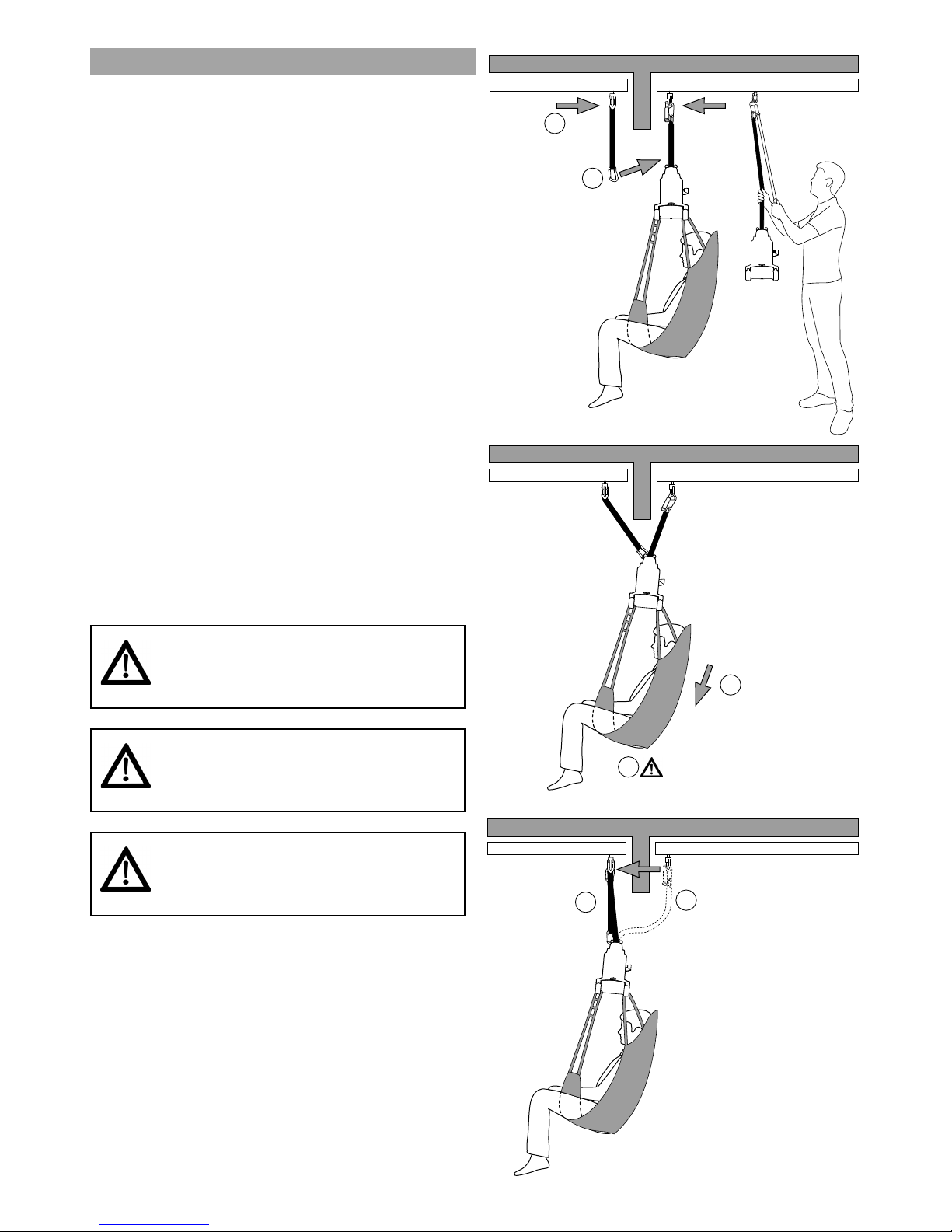
Room to room transfer Molift Nomad
With a climbing band (accessory) it is possible to
transfer a person from room to room through a
doorway between two rail systems that are not
connected, with a portable hoist.
1. Move the hoists and trolley with climbing band
as close as possible to doorway.
2. Lower hoist and connect the climbing band to
the hoist, make sure it is properly connected for
a safe transfer
3. Lower the hoist. The climbing band will take the
load and hoist will move through doorway.
4. Pay attention and make sure user does not
touch the floor
5. Lower the hoist until the climbing band is taking
up all the load, and the hoist lifting band can be
released.
6. Release the hoists lifting band and connect to
trolley in the other room. Run lifter up until the
climbing band can be released. The transfer is
complete.
Never lift the user higher than
necessary to carry out a lift.
Never leave a user unattended in a
lifting situation.
There is a risk of injury to user or
assistant from a swinging lifting
strap, suspension or hand control.
Page 25

25
Molift Rail System / www.molift.com
Page 26
26
Molift Rail System / www.molift.com
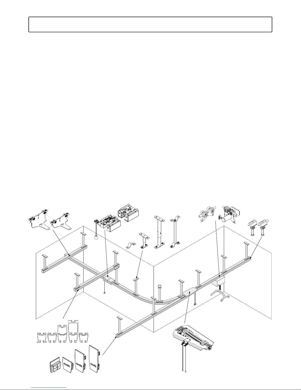
4. Component Overview
This chapter describes the MRS products and
which components are available for different
design solutions. For more details and information
of possible design, restrictions and other conditions see Chapter 5. Design conditions.
Page 27

27
Molift Rail System / www.molift.com
4.1 Attachment
4.1.1 Ceiling Mounted System
MRS includes 5 different attachments of ceilings
mounted systems.
1. Direct in ceiling which does not require any
attachments, just bolts directly into the ceiling
(Requires H62 DC profile).
2. Fixed Bracket. 40mm height. Two fixing points
to ceiling
3. Telescope Thread Bracket. 80-200mm. Two
fixing points to ceiling
4. Telescope Bracket. Two parts. 190-2000mm.
Two fixing points to ceiling
5. Threaded Rod. One or two fixing points to
ceiling. Comes in two lengths. Cut to length at
installation site.
Article no.
1109 6 9 5 Ceiling bracket set 40 mm
110970 0 Telescope Thread 80-125mm
1109710 Telescope Thread 120-200mm
1109715 Telescope 190-250mm
1109718 Telescope 240-350mm
1109720 Telescope 340-550mm
1109725 Telescope 540 -900mm
110973 0 Telescope 890-1300mm
1109735 Telescope 1290-2000mm
1109910 M10 Threaded Rod w/Bracket Set 1
Meter
1109 912 M10 Threaded Rod w/Bracket Set 2
Meter
3. Telescope Thread
80 -200mm
4. Telescope
190-2000mm
5. Threaded Rod
100-2000mm
2. Bracket
40mm
Page 28

28
Molift Rail System / www.molift.com
Bracing Side supports
Rails systems mounted with attachments like
Telescope brackets and Threaded rods need bracing in form of Side supports to eliminate horizontal
forces and vibrations. (Design and positioning of
Side support see chapter 5.2.4)
Support for Telescope or Threaded rod Ceiling
Bracket, for mounting in rail.
Article no.
1109 920 M10 Support Set 1 Meter
1109 92 2 M10 Support Set 2 Meter
1109 9 5 0 3/8” Support Set 36”
1109 9 5 2 3/8” Support Set 72”
Support for mounting around telescope ceiling
bracket.
Article no.
1109 815 Side Support unit for Telescope
Brackets
Page 29
29
Molift Rail System / www.molift.com
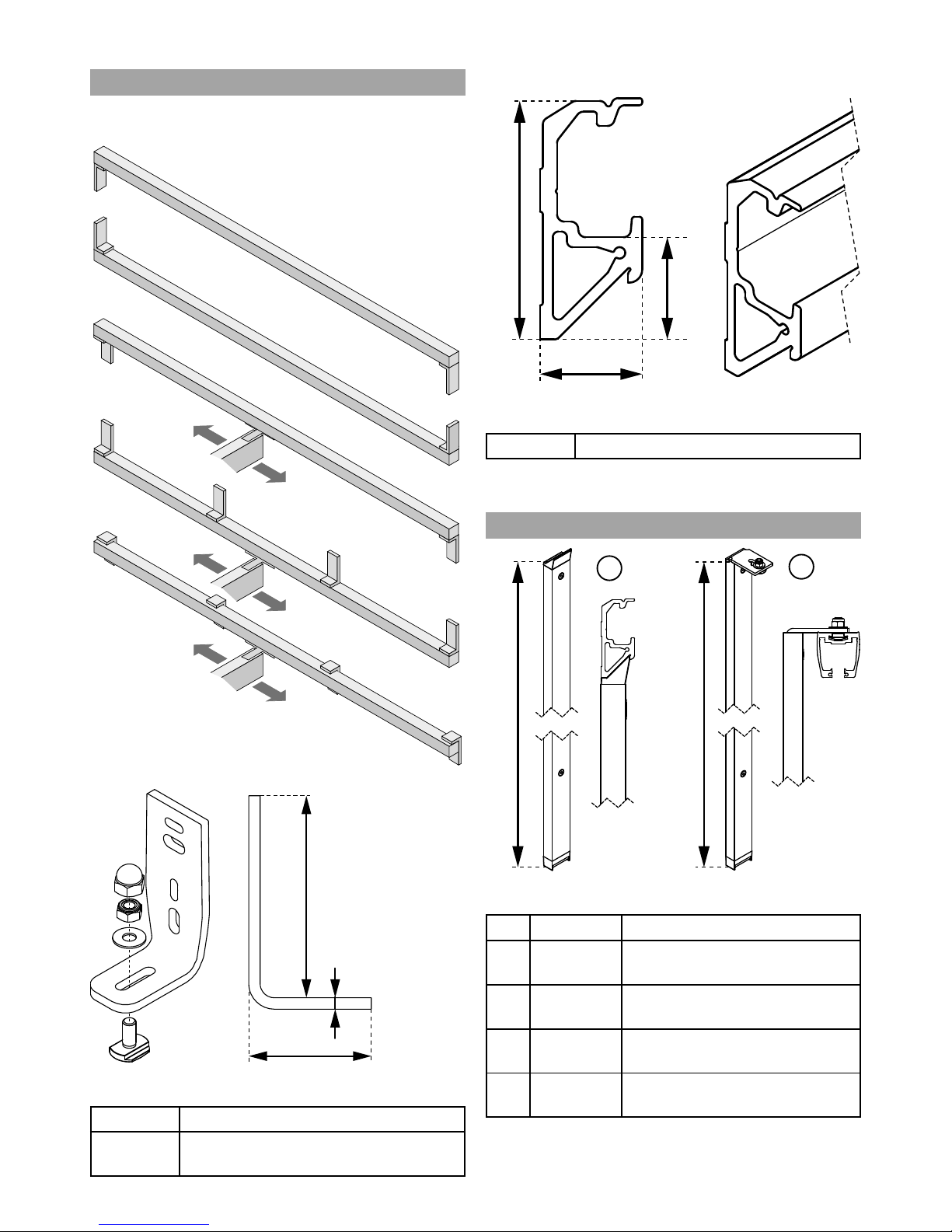
4.1.2 Wall mounted System
Wall mounting bracket is versatile and can be
mounted in different ways.
142
86
8
Article no.
1109259 Wall bracket with multibolt, white
1109269 Wall bracket with multibolt,
anodized
Wall rail
36
36
85
Article no.
1109160 Rail H85 W/A 6m-length painted
Upright Support
2500 / 3500
2500 / 3500
Article no.
Pos. Article no.
1 1109210 Wall support W-rail
L=2500mmm
1 1109215 Wall support W-rail
L=3500mmm
2 11092 2 0 Wall support OC-rail
L=2500mmm
2 1109225 Wall support OC-rail
L=3500mmm
1
2
Page 30
30
Molift Rail System / www.molift.com
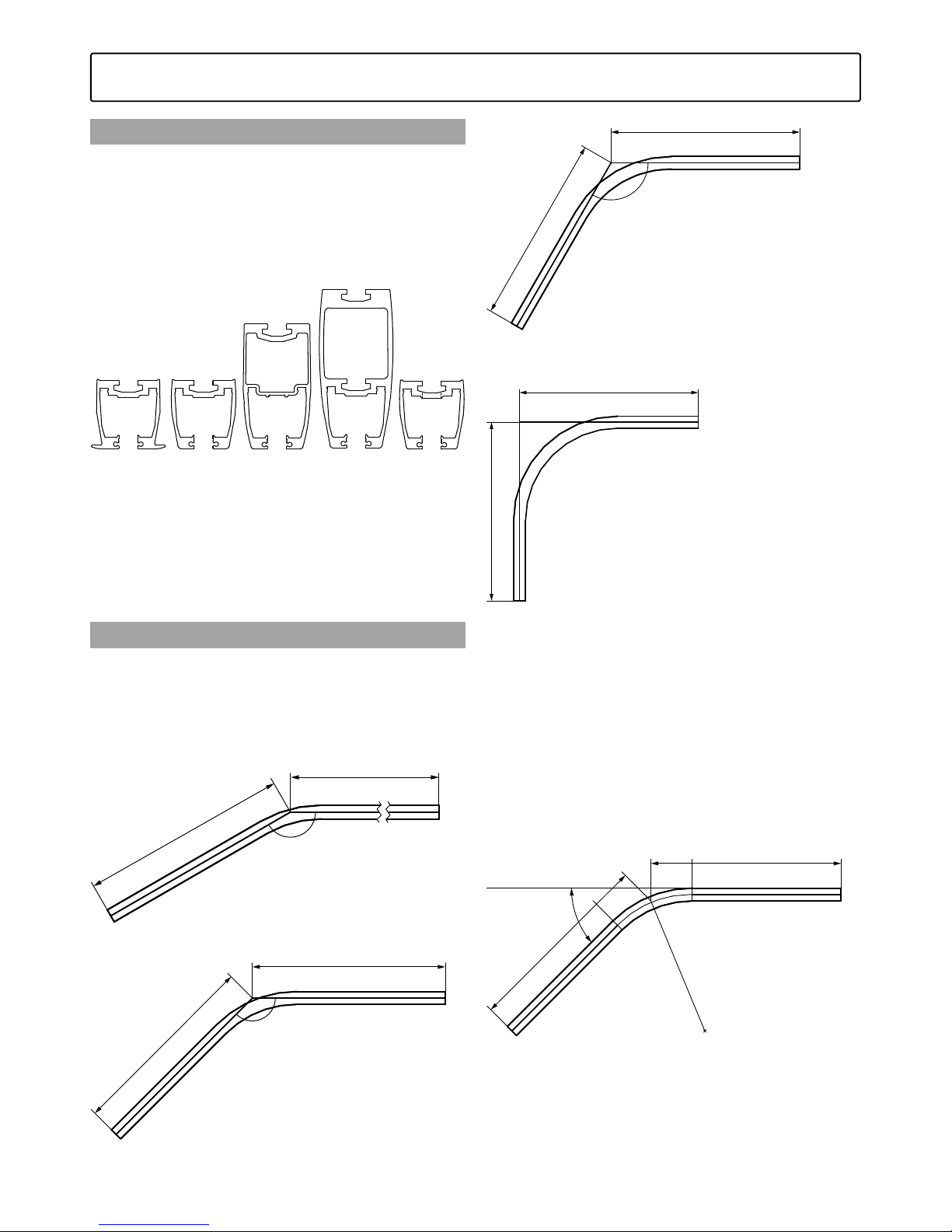
Rails
MRS rail program consists of 4 different profiles
(CC, OC, DC or W) where OC profile is available
in 3 different heights. The figures give the height
of the rail in mm. The strength of the rail relates
to the height. Higher profile gives stronger rail. All
profiles are compatible with all combinations of
the MRS products.
All rails are extruded Aluminum and comes in
two colours, anodized aluminum and white paint.
The H62 rail comes in 3 different versions, CC for
recessed rails flush to false ceiling, DC for direct
mounting in ceiling, and OC for suspended rails
from bearing ceiling.Delivered in standard lengths
or Tailor made lengths up to 7,0m.
Curves
Rail curves are available for all three H62 profiles
and come as standard in 30, 45, 60 and 90
degrees angle. Tailor made curves are possible as
well as tailor made lengths. All curves have radius
550mm. Standard length is 1000mm.
30°
1000mm
1000mm
Curve 30°
1000mm
1000mm
45°
Curve 45°
1000mm
1000mm
60°
Curve 60°
1000mm
1000mm
90°
Curve 90°
Special Curve CC/DC/OC
Tailor made curve angles can be ordered. Use part
no. 1109150 for special curves in Rail H62 profile
and specify the colour (P or A) and following
measurements when ordering:
A= 0 – 2000mm : _______
B= 0 – 2000mm : _______
C= 0-90° : _______
Dimension A
Dimension B
Dimension C 0°-90°
Top View
R 550mm, center of rail
4.2 Rails and Curves
Page 31
31
Molift Rail System / www.molift.com
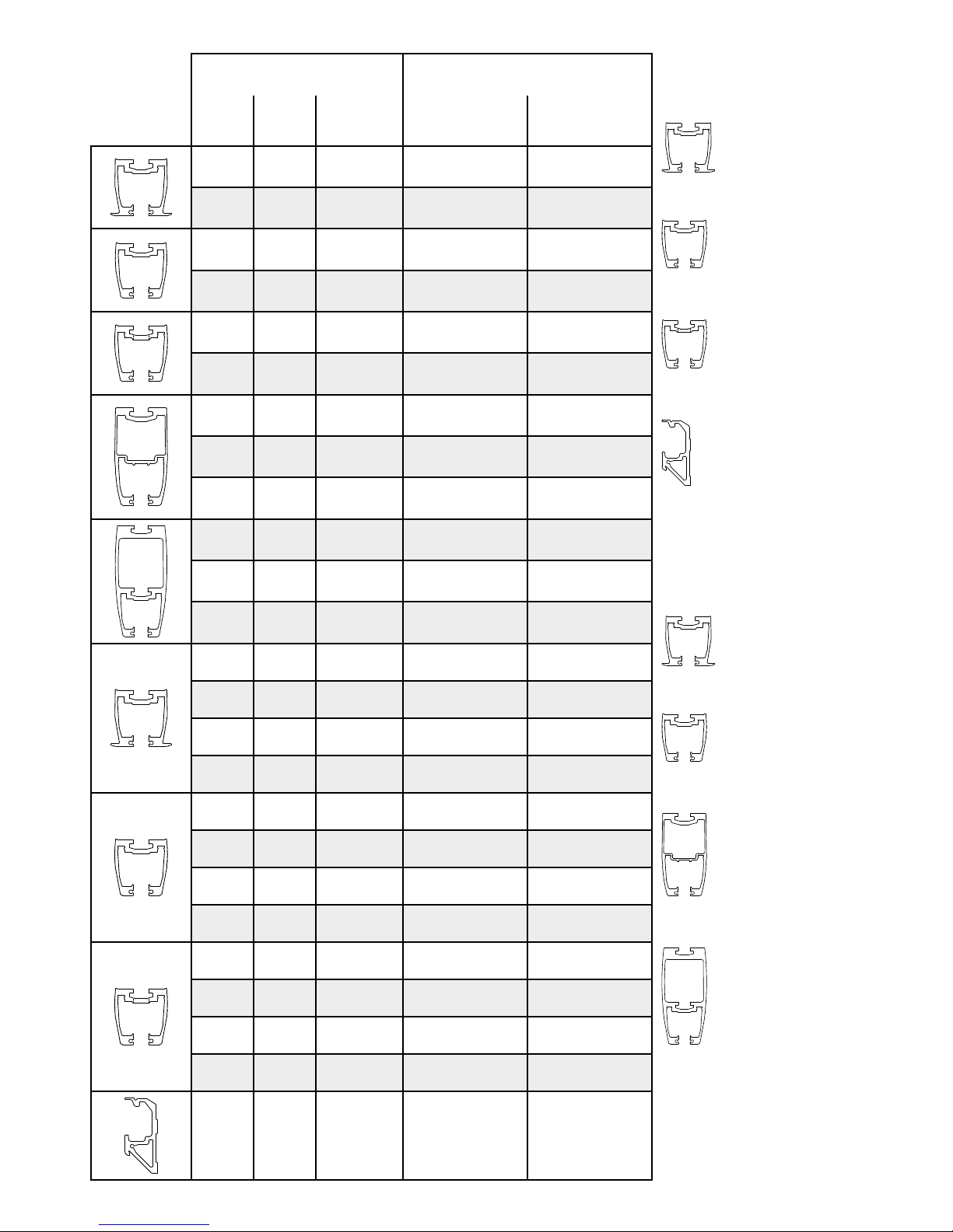
Rail profile Surface treatment
Height Profile
Length or
Curve
Anodized
(article no.)
Painted
(article no.)
H62 CC 6m 1109000-6m 1109 0 01- 6 m
H62 CC 7m 1109000-7m 110 9 0 01-7m
H62 OC 6m 110 90 02- 6m 110 9 0 03 - 6m
H62 OC 7m 1109 0 02-7m 110 9 0 03 -7m
H62 DC 6m 110 90 0 4 - 6 m 110 9 0 05 - 6m
H62 DC 7m 1109 0 0 4 -7m 1109 0 0 5 -7m
H112 OC 4m 1109 0 0 8 - 4 m 1109009-4m
H112 OC 5m 1109 0 0 8 -5m 1109009-5m
H112 OC 6m 110 9 0 0 8 - 6 m 1109009-6m
H142 OC 5m 1109010-5m 110 9011-5m
H142 OC 6m 1109010-6m 110 9 011- 6m
H142 OC 7m 1109010-7m 110 9 0 11-7m
H62 CC 30° 1109100 1109105
H62 CC 45° 1109101 1109106
H62 CC 60° 1109102 1109107
H62 CC 90° 1109103 1109108
H62 OC 30° 110913 0 1109135
H62 OC 45° 110 9131 110913 6
H62 OC 60° 110 9 132 110 9 137
H62 OC 90° 110913 3 110913 8
H62 DC 30° 110914 0 110 9 145
H62 DC 45° 110 9141 110914 6
H62 DC 60° 110 9 142 110 9 147
H62 DC 90° 110914 3 110 9148
H85 W 6m N/A 1109160
Rail profile
CC = Rail to be built into
closed ceiling
OC = Rail for open ceiling /
and mounting in rafters
DC = Rail to be mounted
directly in concrete ceiling
W = Rail for traverese
system, to be mounted
directly on wall
(H=85 W=36 mm)
Rail profile measurements:
H62 CC
H=62 W=67,3 mm
H62 OC
H=62 W=58,8 mm
H112 O C
H=112 W=61,7 mm
H142 OC = 142 mm
H=142 W=66 mm
Surface treatment
Anodized = Matte alloy
Painted = White
Page 32

32
Molift Rail System / www.molift.com
End Stops
End stop is an important safety detail for all
Overhead systems. All rail ends must have an End
stop to prevent trolleys from going out of the rail.
The end stop can also be used to limit the range
of lifting area.
45mm
Ø11
Use drill guide 1109998 to mount end stop.
Pos. Article no.
1 1109410 End stop for motor trolley
2 110 9 411 End stop for traverse trolley
Check to ensure that the end stops
are assembled into all rail ends in
the overhead system.
End caps
Plastic caps for covering rail ends. Comes in two
colours for all three different rail heights, grey and
white. (for combination with anodized or white
rails)
Article no.
1109320 End Cap Rail H62 Grey
1109321 End Cap Rail H12 Grey
1109322 End Cap Rail H142 Grey
110934 0 End Cap Rail H62 White
1109341 End Cap Rail H112 White
1109342 End Cap Rail H142 White
White plastic sleeve
To be used as cover for ceiling bracket when going
through false ceiling.
Article no.
For threaded rod system:
1120338 Sleeve LKF62/28,5/7 White
For telescope bracket (upper part):
1109 817 Sleeve RKW 1 1/2-50 White
4.3 End Stops and End Caps
1 2
Page 33

33
Molift Rail System / www.molift.com
Traverse trolleys
MRS Traverse trolleys are used in all traverse systems which uses H-profile as primary rails. Comes
in two versions, Standard and lowered 50mm.
Delivered in a complete set with two trolleys.
51
206
Primary Rail
Article no.
110955 0 Traverse trolley set (grey)
110959 0 Traverse trolley set (white)
101
206
Primary Rail
Article no.
1109570 Traverse trolley set 50mm+ (grey)
11095 8 0 Traverse trolley set 50mm+ (white)
Boxed traverse trolleys
Boxed traverse trolleys have lower building height,
and curtain pass through (CPT) version (with boggie wheels) can be used in rail systems with gap
for curtains.
224
13
Primary Rail
Article no.
1109592 Boxed traverse trolley set, white
1109593 Boxed traverse trolley set, grey
110959 6 Boxed traverse trolley CPT set, white
1109597 Boxed traverse trolley CPT set, grey
Figure: Curtain pass through.
4.4 Traverse Trolleys
Page 34

34
Molift Rail System / www.molift.com
Traverse Mounting kit
Article no.
1109345 Traverse mounting kit (under trolleys)
Article no.
1109353 Traverse mounting kit (between
primary rail)
Traverse Trolley for Wall rail
Traverse Trolley for Wall Rail (Includes end stops)
52,5
42,5 247
51,5
165
82
165
Wall,
Rail H85 W
Wall,
Rail H85 W
116
52,5
42,5 247
51,5
165
82
194
145
Article no.
110916 3 Wall mounted traverse trolley set
RH112
110916 6 Wall mounted traverse trolley set
RH142
Page 35
35
Molift Rail System / www.molift.com
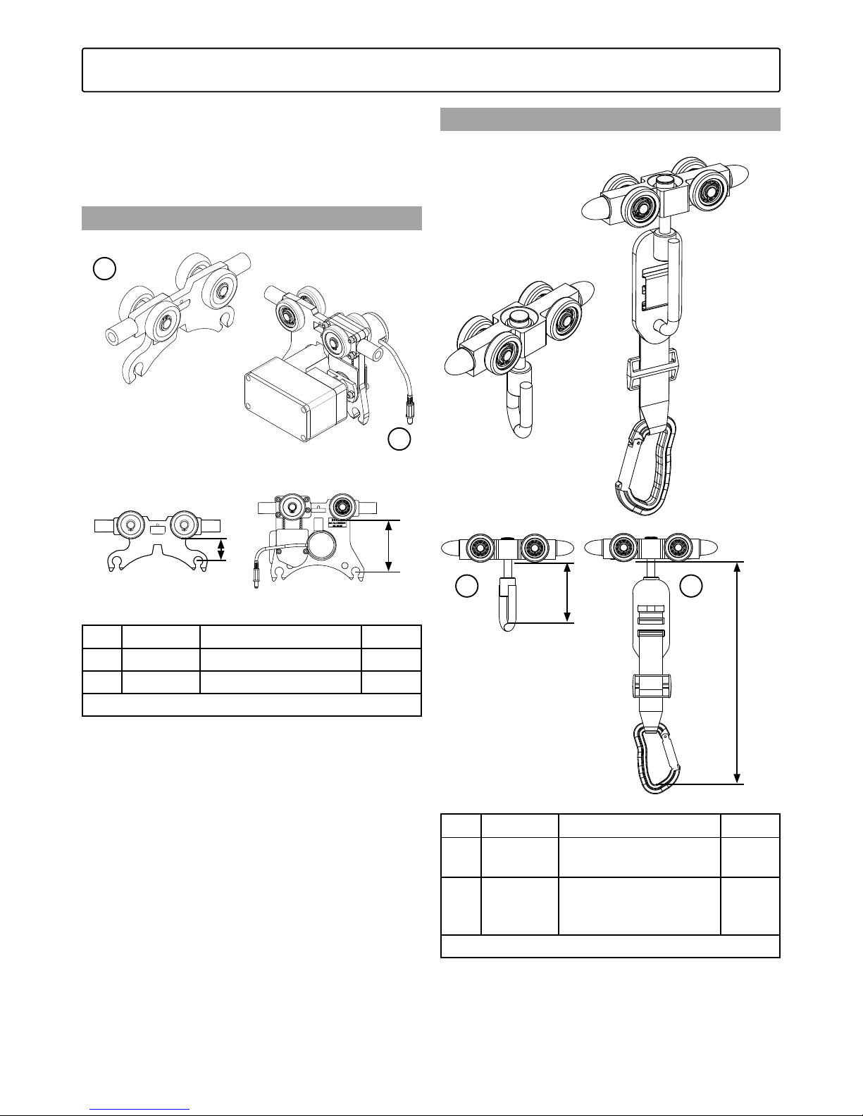
Lift motor trolleys are available in various versions
for Molift AIR and Molift Nomad. All motor
trolleys are compatible with all rail profiles and all
combinations of MRS products.
Molift AIR
Pos. Article no. L
1 2520000 Basic Trolley 29,6
2 2500103 Trolley Propulsion 72,6
All measurements in mm.
Molift Nomad
Trolley for Molift Nomad
L
L
Pos. Article no. L
1 1109109 Trolley Molift Nomad
w brake, MRS
80
2 110 9112 Trolley Molift Nomad
for climbing w brake,
MRS
295
All measurements in mm.
4.5 Lift Motor Trolleys
1
1 2
2
L
L
Page 36
36
Molift Rail System / www.molift.com
Molift Rail System has 2 different options of
switching direction within the MRS range.
Rail Switch
For Single rails, switching direction from straight
rail to curve etc. Manually controlled.
Article no.
1109 015 Switch MRS (grey)
1109066 Switch MRS (white)
1109 0 8 5 Set of covers for OC rail switch (grey)
1109 0 8 6 Set of covers for OC rail switch
(white)
1109 0 7 7 Set of covers for CC rail switch (grey)
1109 0 7 8 Set of covers for CC rail switch
(white)
Traverse Switch
For transfer from traverse system to a fixed rail.
Manually controlled.
Article no.
1109 0 2 9 Traverse Switch Unit (grey)
1109 6 5 0 Traverse Switch Unit (white)
Article no.
1109602 RH62 OC/A modified for transition
co upling (L=6m)
1109 6 5 7 RH62 OC/P modified for transition
co upling (L=6m)
1109603 RH142 OC/A modified for transition
co upling (L=6m)
1109 6 5 8 RH142 OC/P modified for transition
co upling (L=6m)
4.6 Switches
Page 37

37
Molift Rail System / www.molift.com
Charging
Molift Nomad and Molift AIR are charged with
external charger via hand control.
External charging via handcontrol
Charger mounted on wall or table connected to
motor with hand control
Article no.
124 0100 Charger for handcontrol Nomad/AIR
4.7 Battery Charging
Page 38

38
Molift Rail System / www.molift.com
Page 39

39
Molift Rail System / www.molift.com
Page 40

40
Molift Rail System / www.molift.com
Drill guide
Drill guide for Direct mounting of rail in concrete Ø
8,0mm, and Drill guide for End stops Ø 11mm
Article no.
1109999 Drill guide Ø8 mm for RH 62 DC
1109998 Drill guide Ø11 mm for endstop
Multibolt M10
Used for all connections with brackets into rail
profile.
Article no.
2520221 Multibolt kit
T-Profile washer
Used for direct mounting and for all end stops
Article no.
1109307 T-Profile washer MRS
Shims
Used for support to level brackets.
Article no.
1109312 Shims 0,5 for MRS
1109313 Shims 1,0 for MRS
1109314 Shims 2,0 for MRS
Joint set – Washer and sprints.
Used for joining rails of same profile in straight
rails or curve rail system.
Article no.
1109350 Joint set for MRS
Mounting plate for mounting of rail switch.
Article no.
1109090 Rail Mounting plate Assy Switch
MRS
4.8 Installation tools
Page 41

41
Molift Rail System / www.molift.com
Page 42

42
Molift Rail System / www.molift.com
5. Design Conditions
This chapter describes the design conditions, limitations and possibilities how to combine the MRS
products to create a sufficient and safe Molift
Overhead System.
5.1 Lifting heights and lifting areas
Recommended heights
The Overhead system working height measures
between the lower point of the rail to which the
lift motor are attached (straight rail or secondary
rail) and down to the floor of the room. Normally
the recommendation is to position the rail from
2300mm to 4000 for a Molift AIR motor depending on the ceiling heights and lifting needs. We
recommend no lower than 1800mm from the
highest position of lifting point of the suspension
down to the floor.
To be able to lift a person from the floor it is
important that the distance from floor to lifting
point of suspension does not exceed 400 mm
when the suspension is at its lowest point as picture shows. The flexibility of MRS and Molift AIR
allows walking training as well as normal patient
transfers within these heights.
Lifting Interval
2000mm
Lifting Interval
3000mm
Max 400mm
Min 1800mm 500mm
510mm
2300-3000mm
2300-4000mm
Min 1800mm
Rail
Rail
Floor
Floor
Max 400mm
Molift Nomad
Molift AIR
(4-point Medium suspension)
Page 43

43
Molift Rail System / www.molift.com
Lifting area limitations
An Overhead system covers a certain maximum
lifting area in a room. Due to the practical installation work and measurements of including parts,
a rail system cannot be mounted directly close
to the walls. There a few things to consider, the
minimum space between a rail and the wall, the
lengths of end stops, trolleys and lift motor.
Lifting Area = Hatched area
on floor under lifter.
Min. 120mm from wall
Min. 45mm
180mm
97mm
180mm
97mm
261mm
??mm
Min. 120mm
from wall
Min.
45mm
261mm
174.5mm
Page 44

44
Molift Rail System / www.molift.com
5.2 Design conditions – Attachments
Maximum distances between attachments to
fulfill maximum deflection requirements according
to ISO standard 10535 (<1mm per 200mm rail
length). Depending on Safe Working load SWL
and rail profile.
5.2.1 Ceiling mounted
A - Maximum distance between attachments
(Including distance between primary rails in
traverse systems)
B - Maximum distance from last attachment to
end of rail (Free end/Overhang)
Safe Working
Load (SWL)
Rail profile A - Max
distance
B - Max
distance
SWL 160 kg Rail H62 CC 2200 mm 400 mm
Rail H62 OC 2200 mm 400 mm
Rail H62 DC 120 0 mm 50 mm
Rail H112 OC 4800 mm 550 mm
Rail H142 OC 6000 mm 700 mm
Rail H85 W 150 0 mm 250 mm
SWL 205 kg Rail H62 CC 2000 mm 400 mm
Rail H62 OC 2000 mm 400 mm
Rail H62 DC 900 mm 50 mm
Rail H112 OC 4200 mm 500 mm
Rail H142 OC 6000 mm 650 mm
Rail H85 W 14 0 0 mm 225 mm
SWL 230 kg Rail H62 CC 1800 mm 400 mm
Rail H62 OC 1800 mm 400 mm
Rail H62 DC 600 mm 50 mm
Rail H112 OC 3900 mm 500 mm
Rail H142 OC 6000 mm 600 mm
Rail H85 W 13 0 0 mm 200 mm
SWL 255 kg Rail H62 CC 1700 mm 375 mm
Rail H62 OC 1700 mm 375 mm
Rail H62 DC 300 mm 50 mm
Rail H112 OC 3800 mm 500 mm
Rail H142 OC 5700 mm 600 mm
Rail H85 W 1250 mm 175 mm
SWL 300 kg Rail H62 CC 1600 mm 375 mm
Rail H62 OC 1600 mm 375 mm
Rail H62 DC 300 mm 50 mm
Rail H112 OC 3500 mm 450 mm
Rail H142 OC 5300 mm 550 mm
Rail H85 W 1200 mm 150 mm
B
A
A
B
B
A
A
B
B
Page 45

45
Molift Rail System / www.molift.com
5.2.2 Wall mounted
A - Maximum distance between attachments
(Including distance between primary rails in
traverse systems)
B - Maximum distance from last attachment to
end of rail (Free end/Overhang)
Safe Working
Load (SWL)
Rail profile A - Max
distance
B - Max
distance
SWL 160 kg Rail H62 CC 2200 mm 400 mm
Rail H62 OC 2200 mm 400 mm
Rail H62 DC 1200 mm 50 mm
Rail H112 OC 4800 mm 550 mm
Rail H142 OC 6000 mm 700 mm
Rail H85 W 1500 mm 250 mm
SWL 205 kg Rail H62 CC 2000 mm 400 mm
Rail H62 OC 2000 mm 400 mm
Rail H62 DC 900 mm 50 mm
Rail H112 OC 4200 mm 500 mm
Rail H142 OC 6000 mm 650 mm
Rail H85 W 1400 mm 225 mm
SWL 230 kg Rail H62 CC 1800 mm 400 mm
Rail H62 OC 1800 mm 400 mm
Rail H62 DC 600 mm 50 mm
Rail H112 OC 3900 mm 500 mm
Rail H142 OC 6000 mm 600 mm
Rail H85 W 1300 mm 200 mm
SWL 255 kg Rail H62 CC 170 0 mm 375 mm
Rail H62 OC 170 0 mm 375 mm
Rail H62 DC 300 mm 50 mm
Rail H112 OC 3800 mm 500 mm
Rail H142 OC 5700 mm 600 mm
Rail H85 W 1250 mm 175 m m
SWL 300 kg Rail H62 CC 1600 mm 375 mm
Rail H62 OC 1600 mm 375 mm
Rail H62 DC 300 mm 50 mm
Rail H112 OC 3500 mm 450 mm
Rail H142 OC 5300 mm 550 mm
Rail H85 W 120 0 mm 150 mm
A
A
B
B
A
A
B
B
A
A
Page 46

46
Molift Rail System / www.molift.com
Wall mounted - Wall Rail
A - Maximum distance between wall rail attachment points or upright supports for wall rail
B - Maximum length of secondary rail
C - Maximum distance from last attachment to
end of wall rail (Free end/Overhang)
D - Minimum distance from wall in one end. This
distance is necessary for installing secondary rail
with trolley in wall rail. Minimum distance = 350
mm
Safe Working
Load (SWL)
Rail profile
A Max
distance
B Max
distance
C Max
distance
SWL 160 kg Rail H62 CC
Rail H62 OC 2200
Rail H62 DC
Rail H112 OC 4800
Rail H142 OC 6000
Rail H85 W 150 0 250
SWL 205 kg Rail H62 CC
Rail H62 OC 2000
Rail H62 DC
Rail H112 OC 4200
Rail H142 OC 6000
Rail H85 W 14 0 0 225
SWL 230 kg Rail H62 CC
Rail H62 OC 1800
Rail H62 DC
Rail H112 OC 3900
Rail H142 OC 6000
Rail H85 W 13 0 0 200
SWL 255 kg Rail H62 CC
Rail H62 OC 170 0
Rail H62 DC
Rail H112 OC 3800
Rail H142 OC 5700
Rail H85 W 1250 175
SWL 300 kg Rail H62 CC
Rail H62 OC 1600
Rail H62 DC
Rail H112 OC 3500
Rail H142 OC 5300
Rail H85 W 1200 150
All measurements in mm
A
B
C
D
C
D
A
B
Page 47

47
Molift Rail System / www.molift.com
Secondary rail length
Length of Secondary rail (B) is determined by distance between primary rails (A) in a box-in-system,
or the distance between the wall rails (C) for a wall
mounted system.
C
A
B
B
Figure: Secondary rail (B) length
Box in system: Approx 30mm shorter than (A)
Wall rail system: Approx 130mm shorter than (C)
55mm
20mm ±5
55
15mm ±515mm ±5
Figure: Distances between Secondary and Primary
rail.
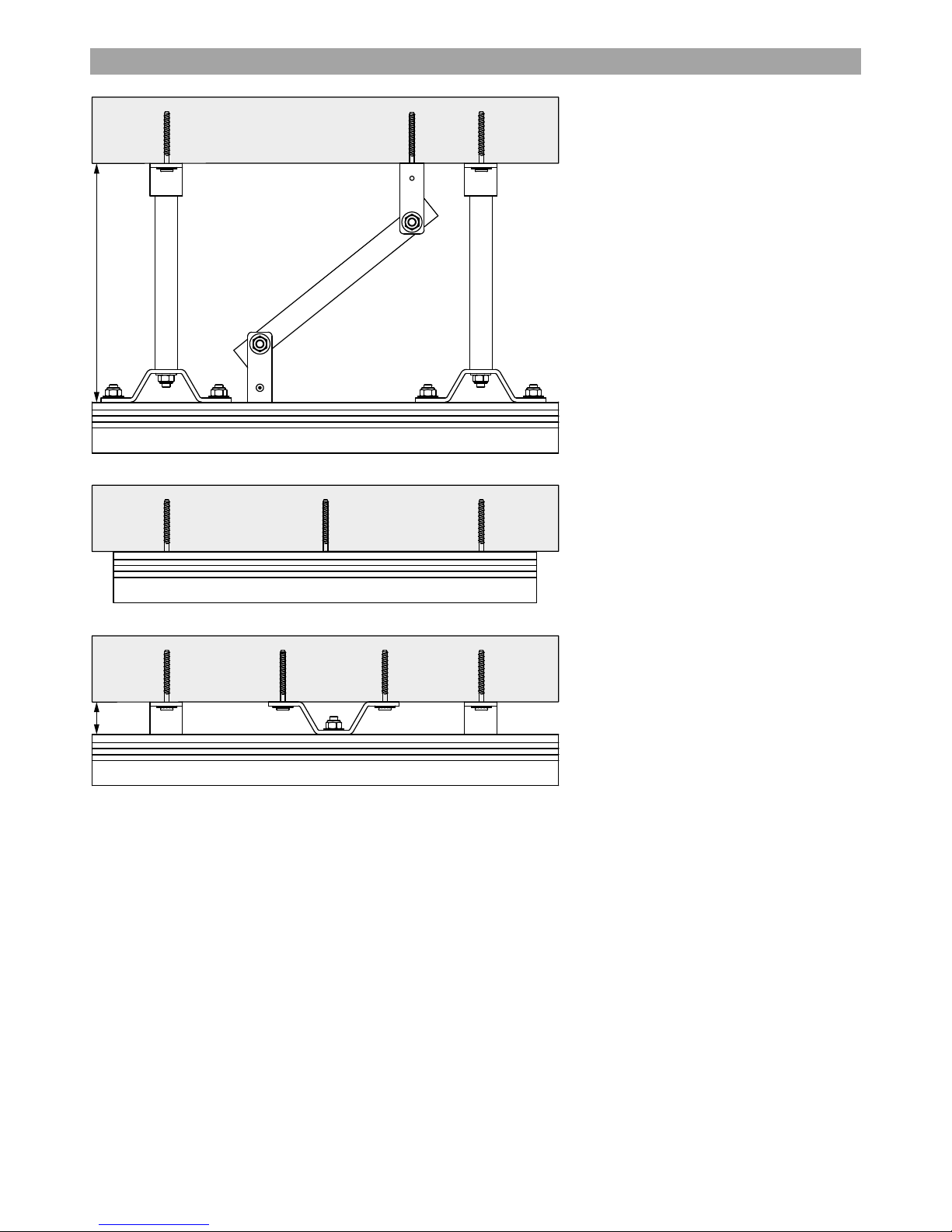
5.2.3 Attachments for curves
Rail curves are only possible for ceiling mounting.
Minimum requirements:
Figure: Minimum three attachments must be
mounted. One in each joint section and one in
center of curve radius.
For joining curves with other rails of same profile a
Joint Set is used.
Figure: Joint set and bracket mounting.
Page 48

48
Molift Rail System / www.molift.com
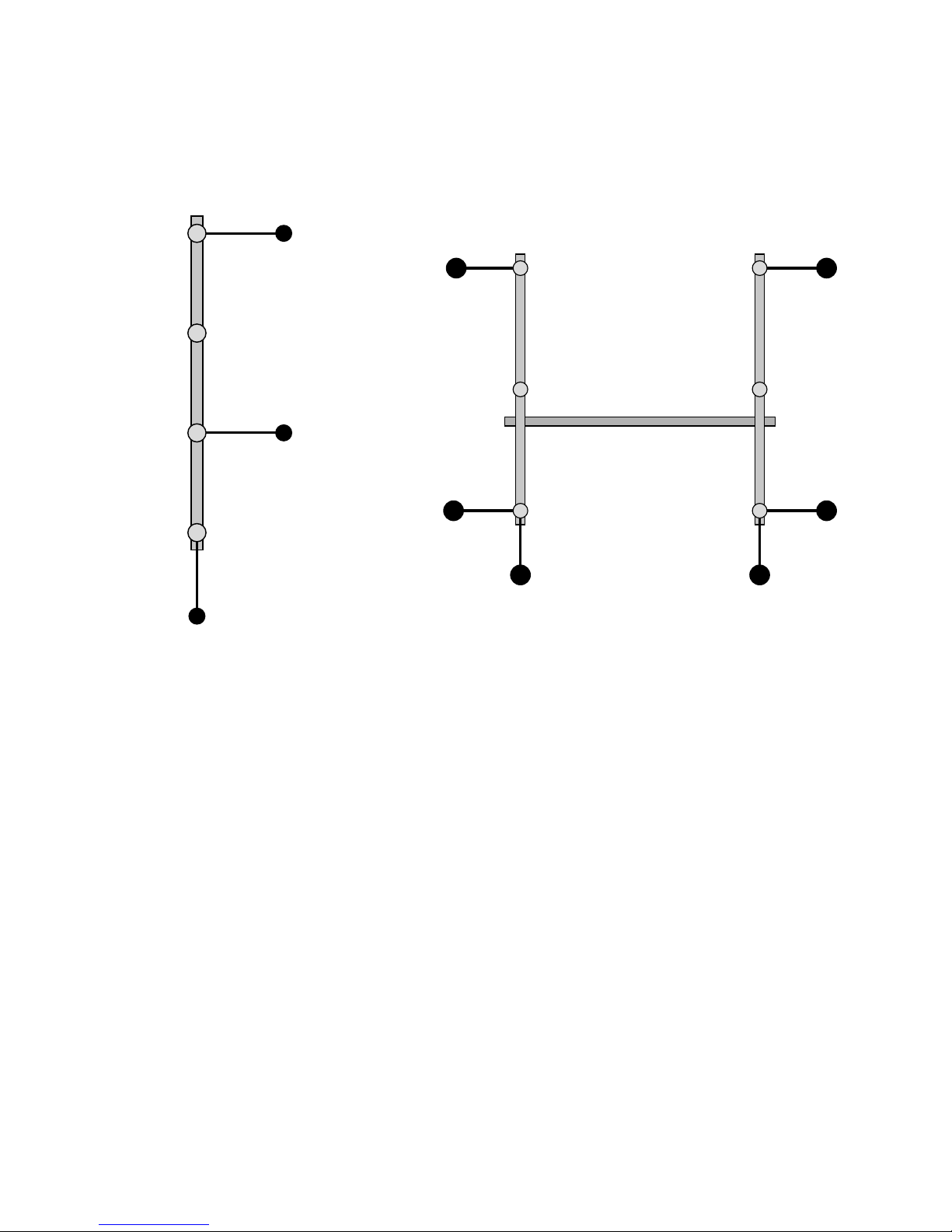
Bracing with side supports is needed to give
stability to ceiling mounted Overhead systems
depending on bracket lengths.
Straight rail and Traverse systems
Length of bracket < 800 mm, (< 32 inch.):
No need of side supports.
Length of bracket 800 > 1500 mm, (32 > 60 inch.):
Side supports should be mounted to the first and
the last bracket and in between those to every
third bracket, positioned perpendicular to the rail
in a Straight rail system and to both primary rails in
a Traverse system.
One Side support should be mounted to the first
or last pendant, positioned parallel to the rail in a
Straight rail system and to both the primary rails in
a Traverse system.
Straight Rail System Traverse System
Telescope Brackets
5.2.4 Side Support positioning
Page 49
49
Molift Rail System / www.molift.com
Length of bracket > 1500 mm ( > 60 inch.):
Side support should be mounted to all brackets
positioned perpendicular to the rail in a Straight
rail system and to both primary rails in a Traverse
system.
Side support should be mounted to the first and
last bracket positioned parallel to the rail in a
Straight rail system. Traverse Systems need one
Side support parallel to each Primary rail end.
Straight Rail System
Traverse System
Page 50

50
Molift Rail System / www.molift.com
Length of bracket < 800 mm ( < 32 inch.):
No need of side supports.
Length of bracket > 800 mm ( > 32 inch.):
One side support should be mounted to the
bracket in the middle of the curve perpendicular to
the radius.
Rules for Side support for the joining rails, see
above.
Length of bracket < 400 mm (< 16 inch.):
No need of side supports.
Length of bracket > 400 mm (> 16 inch.):
All switch functions need minimum two side supports perpendicular to each other mounted on the
closest bracket.
Traverse Switch Side rail switch
Rail Curve 90°
Rail Switches
Rail Curves – includes all angles 30°to 90°
Page 51

51
Molift Rail System / www.molift.com
Page 52

52
Molift Rail System / www.molift.com
Side support should be mounted to all rods,
positioned perpendicular to the rail in a Straight
rail system and to both primary rails in a Traverse
system.
Side support should be mounted to the first and
last rods positioned parallel to the rail in a Straight
rail system. Traverse Systems need one Side support parallel to each Primary rail end.
Straight rail and Traverse systems:
All threaded rod systems should have bracing
independent of length of rod. i.e. 100-2000mm
Straight Rail System
Traverse System
Threaded rod installation
Page 53

53
Molift Rail System / www.molift.com
Length of bracket < 800 mm ( < 32 inch.):
No need of side supports.
Length of bracket > 800 mm ( > 32 inch.)
One side support should be mounted to the rod in
the middle of the curve perpendicular to
the radius.
Rules for Side support for the joining rails, see
above.
Regardless of the lengths of Threaded rods, all
switches need minimum two side supports perpendicular to each other mounted on the closest
rod.
Traverse Switch Side rail switch
Rail Curve 90°
Rail Curves – includes all angles 30° to 90°
Rail Switches
Page 54

54
Molift Rail System / www.molift.com
6. Installation methods
The rail system can only be
installed by certified personnel in
accordance with applicable
installation instructions.
Etac is only responsible for the
system if the rail system with trolley and/or lifting motor has been
supplied by Etac and is installed by
authorised staff.
The lifter’s SWL may NEVER exceed
the SWL of the rail system.
There may never be installed more
than one lifting motor per rail
system.
The SWL of the rail system must be
clearly marked on the rail.
All rail systems must be provided
with end stops and end caps to
prevent the trolleys from running
off the system.
Etac recommends that annual
inspections of the system be carried
out according to “Check points for
periodic inspection”.
Please contact Your Service Partner
or Molift by Etac Customer Support
in case of defects to the rail system.
Tools needed for installation and surveys
Survey tools:
Digital camera
Laser range meter
Measure tape: minimum 5 meter length
Stairs
Flash light
Installation tools:
Security equipment (gloves, helmet, boots, ear
protection plugs)
Laser range meter and folding rule
Laser leveler
Working platform / stairs
Lifting equipment for profiles
Saw and table for cutting profiles
Electric drill (battery powered)
«standard» hand tooling
Lights
Fixing components for MRS
Etac Supply Gjøvik does not supply fixing components for Molift Rail System.
Fixing component examples:
- Mechanical expansion anchors
- Chemical anchors
- Concrete screws
- Wood screws
The Etac certified installer is responsible for providing correct fixing components to each project.
Building structure and material on site must be
evaluated before choosing fixing components. The
details and knowledge of this should be established during site survey. The fixing components
must meet the requirements in ISO 10535:2006
described in chapter “2.4 Point loads”.
The final installation procedure will verify the
installation before it is taken into use.
Page 55

55
Molift Rail System / www.molift.com
Principle work flow for OH installation
Recommended steps below to be performed by
installer on site:
1. Measurements – verify dimensions in drawings /
results of site survey
a. Report any mistaken dimensions or
failures early in the project
b. Place the profiles on floor according
to layout – do you have to modify
profiles?
What about the planned placement
of the charging stations? Are they
correc t?
2. Locate and mark fixing points
a. On the rails use a laser beam to
identify locations of the fixings /
holes
b. Does the planned installation make
any conflicts with other installations
/ suspended ceiling grid (are the grid
already in place?)
3. Drill holes
a. Use correct dimensions on drill bit
according to the manufacturers
specifications. (diameter / depth)
b. Remove dust and remains after
drilling
4. Mount fixings and attachments
a. Fix brackets to ceiling
b. Roughly adjust telescopes and
threaded rods (laser leveller)
5. Elevate rail system
a. Insert all multibolts necessary. Insert
from the profile end.
b. Elevate MRS rails and curves to
brackets
6. Lock profiles to brackets
a. Join rail with joint sets
b. Use correct tightening torques
according to installation instructions.
c. Loctite where necessary according
to installation instructions
7. Mount trolleys and end stops
a. Single / straight systems
b. Traver ses
c. Combined systems
8. Mount lift motor
a. Trolley
b. Charging stations
c. Start up lift motor
9. Check installations acording to Checklist for
installation of Molift Rail System
Page 56
56
Molift Rail System / www.molift.com
7. Final Installation Procedure
After finished installation a load test (according to
ISO 10535:2006) must be performed. Maximum
Safe Working Load shall be applied on all
mounted attachments. Perform at least six lifts
(lift height approx. 15 cm/6 inches) SWL at min. 6
randomly selected points along the rail.
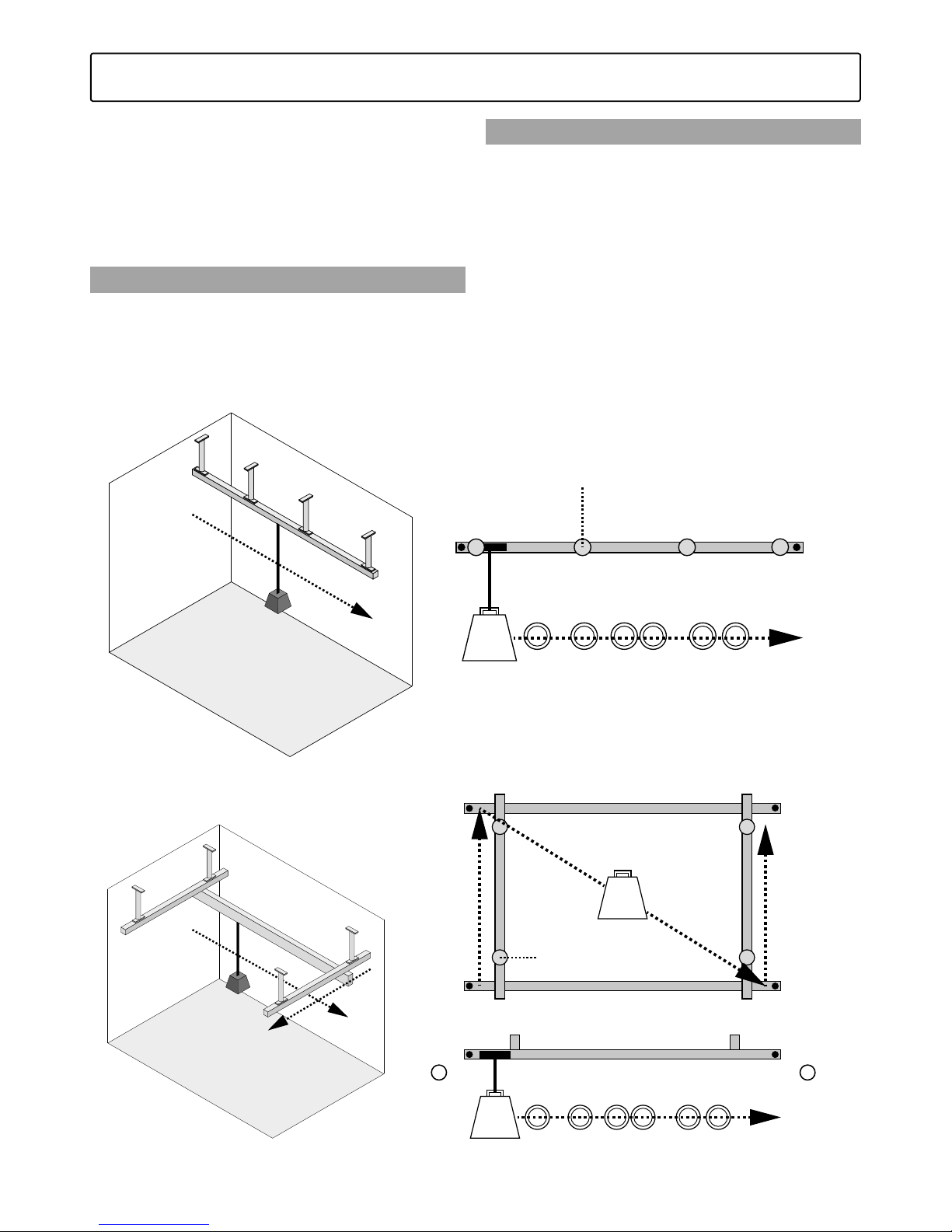
7.1 Load test: Straight Rail System
Lift the load approx. 15cm to apply the maximum
load. Travel the applied load along the rail from
one end stop to the other end stop, with a 10
second pause under each attachment point. Travel
as the dashed line shows in picture.
7.2 Load test: Traverse Rail System
Apply the maximum load for the installed
overhead rail system. Place the carriage with the
applied load at the end stop of the secondary rail
(1). Move the secondary rail, with a pause under
each attachment point, from one end stop to the
other end stop of the first primary rail. Continue
by moving the applied load diagonally through
the centre of the system over to the other side, as
the dashed line shows. Now continue by moving
the secondary rail with the applied load, from (2),
with a pause under each attachment point, from
one end stop to the other end stop of the second
primary rail.
MAX
LOAD
Pause under Attachments
Rail
End StopEnd Stop
Lift at 6 random points
Pause under
Attachments
MAX
LOAD
MAX
LOAD
Secondary Rail
End Stop
End Stop
End Stop
Primary RailPrimary Rail
Lift at 6 random points
End Stop
End Stop
End Stop
1 2
Figure: Load test: Straight Rail System
Figure: Load test: Traverse Rail System
Page 57

57
Molift Rail System / www.molift.com
7.3 Identification
After an approved test load procedure the overhead system is ready for identification marking.
This marking is made with a decal rail marking
on which the maximum load is to be stated. The
decal must be placed clearly visible on the rail in
the system to which the lift motor is attached.
When a Periodic Inspection of the system is
performed a test symbol will be placed in the
circular area on the rail decal marking. A Periodic
Inspection of the overhead system must be made
at least once a year.
Article no.
1109 014 MRS Label, SWL
SWL labels are supplied together with end stop.
7.4 Installation Certification
After approved functional and maximum load test
the installation will be finalized by the issue of
Checklist for installation of Molift Rail system as an
installation certificate. The installation certificate
has to be issued by installation personnel authorized by Etac.
Decal position for identification of SWL for Overhead
system
Molift Rail System installed by authorized personnel.
Date: Etac Molift Service ID SWL: kg
.................. (6 digits):..................... ................ lbs
Periodic
inspection
performed
www.molift.com
Page 58

58
Molift Rail System / www.molift.com
8. System configuration - Examples
This Chapter describes a few of the most common
design solutions of Molift Rail System. Shows
combination possibilities, measurements and
specifications. For each examples of configuration
there is a reference to the Installation Instructions
in chapter 9.
Page 59

59
Molift Rail System / www.molift.com
8.1 Single Rail system
Straight rail system - Ceiling mounted suspended
Straight rail system
Ceiling mounted
Suspended mounted
Telescope bracket (Threaded)
Straight rail system
Ceiling mounted
Suspended mounted
Telescope bracket
80-200
190-2000
Configuration example:
Products Description Incuding Item no Qty
Rail profile Rail H62 OC/A - 6m-length 1109 0 02- 6 m 1
Brackets Telescope Bracket Set 890-1300 mm 110973 0 3
Side Support unit for Telescope Brackets 110 9 815 3
End stops End stop for motor trolley 1109410 2
Endcaps End Cap Rail H62 Grey 1109320 2
Page 60
60
Molift Rail System / www.molift.com
Straight rail system
Ceiling mounted
Suspended mounted
Threaded rod bracket
Straight rail system
Ceiling mounted
Direct mounted
Rail H62 DC
Straight rail system
Ceiling mounted
Direct mounted
Rail H62 DC
Ceiling bracket 40mm
40
Max
2080
Straight rail system - Ceiling direct mounted
Page 61

61
Molift Rail System / www.molift.com
Straight rail system
Wall mounted
Wall bracket
H62 OC
Straight rail system
Wall mounted
Wall bracket
H62 OC
Straight rail system
Wall mounted
Wall bracket
H112 O C
Straight rail system
Wall mounted
Wall bracket
H142 OC
150
62
62
112
142
80
30
Straight rail system - Wall mounted
Configuration example:
Products Description Incuding Item no Qty
Rail profile Rail H62 OC/P - 6m-lengde 1109 0 03 - 6m 1
Brackets Wall bracket unit (White) 1109259 2
End stops End stop for motor trolley 1109410 2
Endcaps End Cap Rail H62 White 110934 0 2
Page 62
62
Molift Rail System / www.molift.com
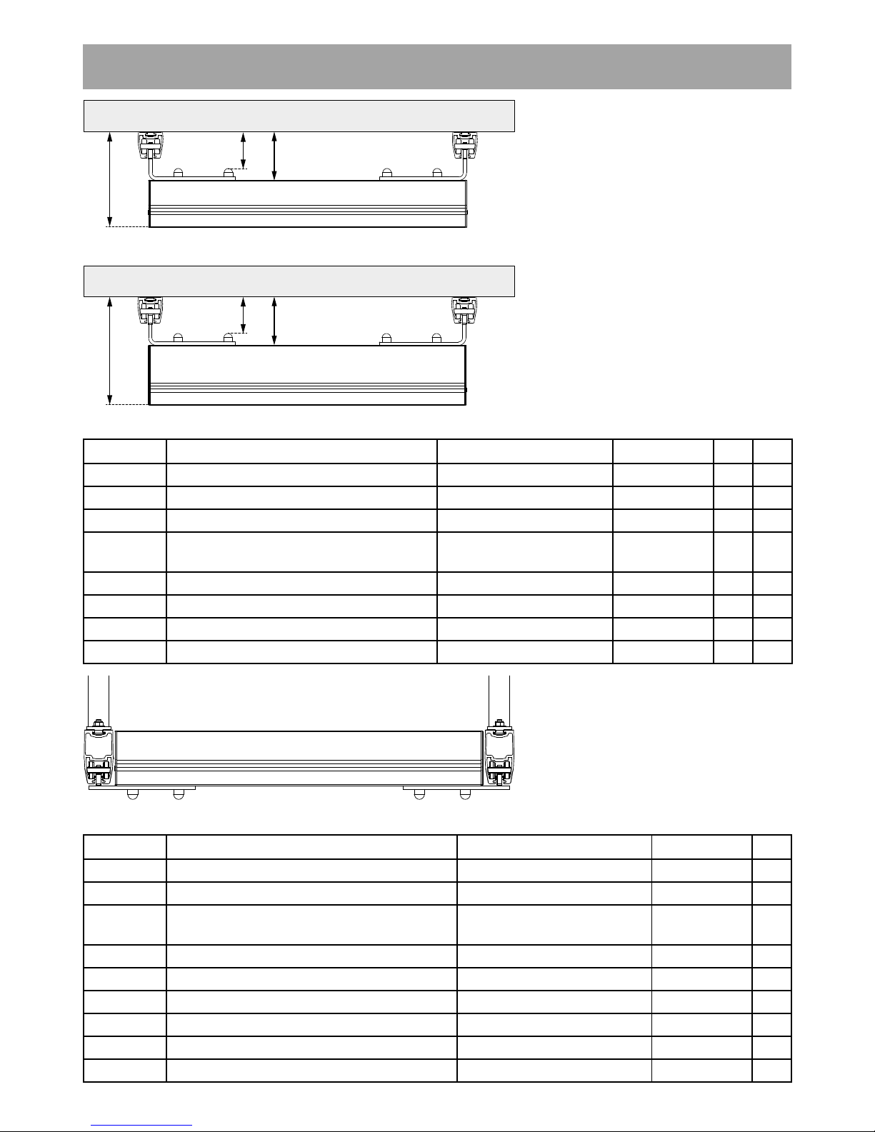
8.2 Traverse Rail system
Traverse rail system - Ceiling mounted suspended
Traverse rail system
Ceiling mounted
Direct mounted
Primary Rail H62 DC
Secondary Rail H112 OC
Traverse rail system
Ceiling mounted
Direct mounted
Primary Rail H62 DC
Secondary Rail H142 OC
Traverse rail system (boxed in)
Ceiling mounted
Suspended mounted
Primary Rail H112 OC
Secondary Rail H112 OC
257
115
227
115
85
85
Configuration example:
Products Description Incuding Item no Qty
Rail profile Rail H62 DC/P 1109 0 0 5 4 2
Rail H112 OC/P 1109009 3 1
Trolleys Traverse trolley set (white) 2 trolleys 110959 0 1
Traverse mounting kit (under trolleys) 2 sets, Bolts, nuts and
washers
1109345 1
End stops End stop for motor trolley 1109410 2
End stop for traverse trolley 1109 411 4
Endcaps End Cap Rail H62 White 110934 0 4
End Cap Rail H112 White 1109341 2
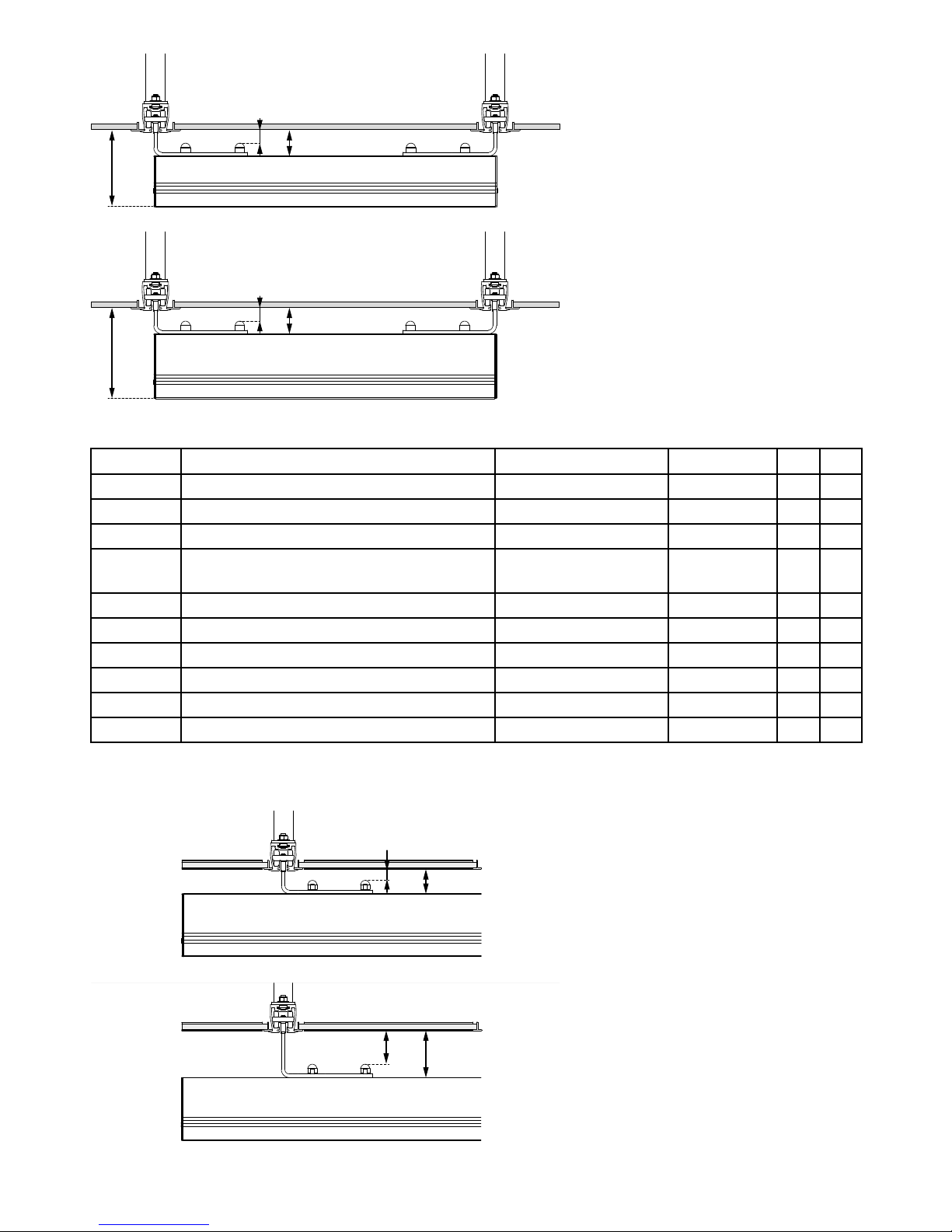
Configuration example:
Products Description Incuding Item no Qty
Rail profile Rail H112 OC/P 1109009 3
Trolleys Boxed traverse trolley set, white 2 trolleys 1109592 1
Traverse mounting kit (under trolleys) 2 sets, Bolts, nuts and
washers
1109345 1
Brackets Telescope Bracket Set 120-200 mm 1109710 6
Side Support unit for Telescope Brackets 110 9 815 6
End stops End stop for motor trolley 1109410 2
End stop for traverse trolley 110 9 411 4
Endcaps End Cap Rail H62 White 110934 0 4
Endcaps End Cap Rail H112 White 110 9 3 41 2
Page 63
63
Molift Rail System / www.molift.com
Configuration example:
Products Description Incuding Item no Qty
Rail profile Rail H62 CC/P 1109 0 01 4 2
Rail H142 OC/P - 4m-length 1109 011- 4 m 1
Trolleys Traverse trolley set (white) 2 trolleys 110959 0 1
Traverse mounting kit (under trolleys) 2 sets, Bolts, nuts
and washers
1109345 1
Brackets Telescope Bracket Set 120-200 mm 1109710 6
Side Support unit for Telescope Brackets 110 9815 6
End stops End stop for motor trolley 1109410 2
End stop for traverse trolley 1109 411 4
Endcaps End Cap Rail H62 White 110934 0 4
End Cap Rail H142 White 11093 4 2 2
Traverse rail system
Ceiling mounted
Suspended mounted
Telescope bracket
Primary Rail H62 CC
Secondary Rail H112 OC
Traverse rail system
Ceiling mounted
Suspended mounted
Telescope bracket
Primary Rail H62 CC
Secondary Rail H142 OC
Traverse rail system
Ceiling mounted
Suspended mounted
Telescope bracket
Primary Rail H62 CC
Secondary Rail H112 OC
Traverse rail system
Ceiling mounted
Suspended mounted
Telescope bracket
Primary Rail H62 CC
Secondary Rail H112 OC
Traverse trolley +50mm
200
58
28
170
58
28
58
28
108
78
Page 64

64
Molift Rail System / www.molift.com
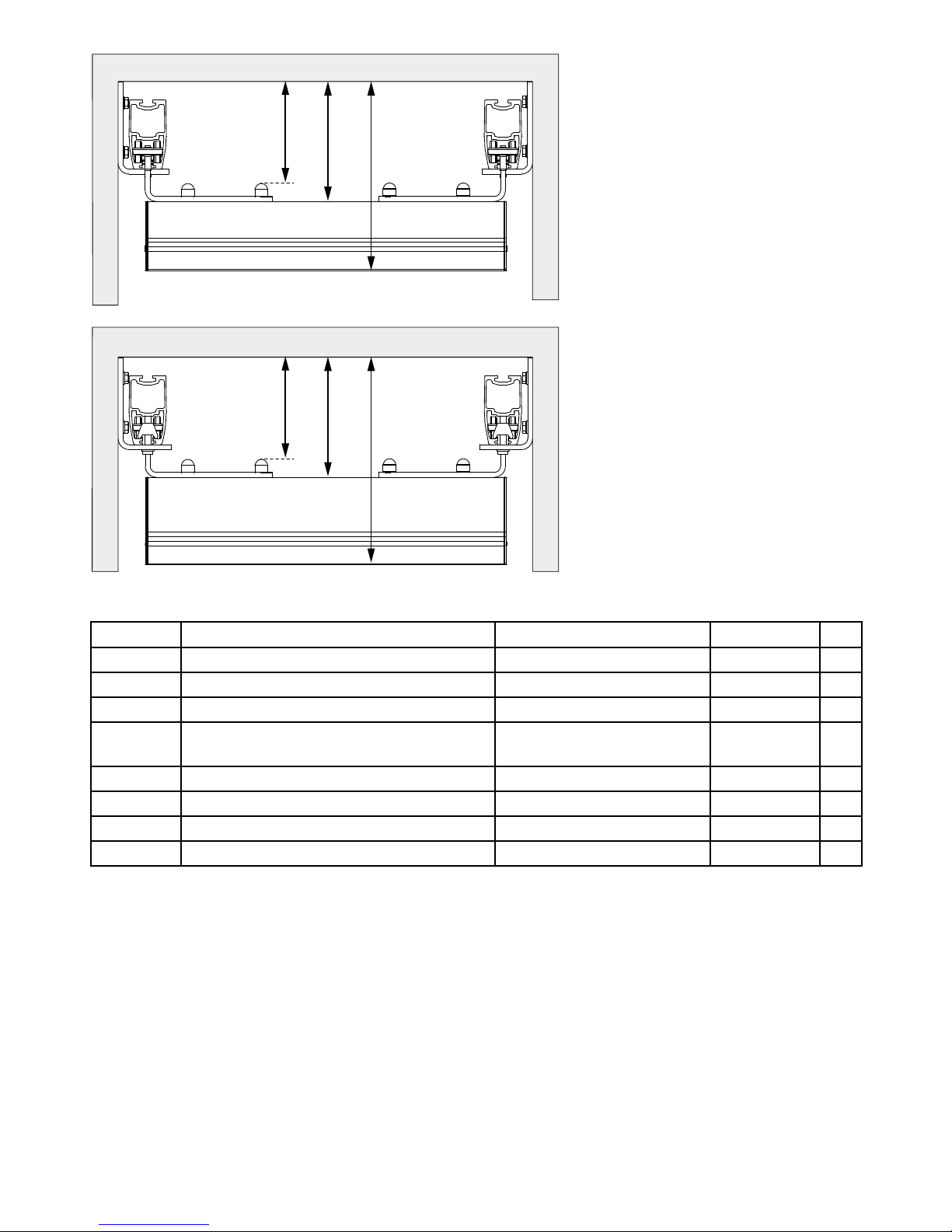
Traverse rail system - Wall mounted
163 51
22
193 51
22
Traverse rail system
Wall mounted
Wall rail
Primary Rail H85 W
Secondary Rail H112 OC
Traverse rail system
Wall mounted
Wall rail
Primary Rail H85 W
Secondary Rail H142 OC
Configuration example:
Products Description Incuding Item no Qty
Rail profile Rail H85 W/A 6m-length painted (4 meter) 1109160 2
Rail H142 OC/P - 4m-length 1109 011- 4 m 1
Trolleys Wall mounted traverse trolley set RH142 2 Trolleys and 4 end
stoppers
110916 6 1
End stops End stop for motor trolley 1109410 2
Endcaps End Cap Rail H142 White 1109342 2
Page 65
65
Molift Rail System / www.molift.com
163
193
335
163
193
305
Traverse rail system
Wall mounted
Wall bracket
Primary Rail H112 OC
Secondary Rail H112 OC
Traverse rail system
Wall mounted
Wall bracket
Primary Rail H112 OC
Secondary Rail H142 OC
Configuration example:
Products Description Incuding Item no Qty
Rail profile Rail H112 OC/P 4m-length 1109009-4m 2
Rail H112 OC/P 4m-length 1109009-4m 1
Trolleys Traverse trolley set (white) 2 trolleys 1109 5 9 0 1
Traverse mounting kit (under trolleys) 2 sets, Bolts, nuts and
washers
1109345 1
Brackets Wall bracket unit (White) 1109259 4
End stops End stop for motor trolley 1109410 2
End stop for traverse trolley 110 9 411 4
Endcaps End Cap Rail H112 White 110 93 41 6
Page 66

66
Molift Rail System / www.molift.com
201
185
123
201
185
73
Traverse rail system
Wall mounted
Wall bracket
Primary Rail H112 OC
Secondary Rail H112 OC
Traverse rail system
Wall mounted
Wall bracket
Primary Rail H112 OC
Secondary Rail H142 OC
Configuration example:
Products Description Incuding Item no Qty
Rail profile Rail H112 OC/P 4m-length 1109009-4m 2
Rail H112 OC/P 4m-length 1109009-4m 1
Trolleys Traverse trolley set (white) 2 trolleys 1109 5 9 0 1
Traverse mounting kit (between primary
rail)
2 sets, Bolts, nuts and
washers
1109353 1
Brackets Wall bracket unit (White) 1109259 4
End stops End stop for motor trolley 1109410 2
End stop for traverse trolley 110 9 411 4
Endcaps End Cap Rail H112 White 110 93 41 6
Page 67

67
Molift Rail System / www.molift.com
9. Installation instructions
Specific Installation Instructions for the various mounting options available upon request to
molift@etac.com. Installation instructions are supplied with the purchased article.
Documents:
Article no. Description Document
1109910, 1109912
1109 9 4 0 , 1109 9 42
MRS Threaded Rod 19-514 installation instruction.pdf
1109 920 , 1109 9 2 2
1109 9 5 0, 110 9 952
MRS Threaded Rod support 19-515 installation instruction.pdf
1109 6 9 5, 110 9 7 0 0
1109710, 1109715
1109718 , 11097 2 0
1109725, 110 9 7 30
1109735
40 mm bracket
1109700, 1109710 Threaded Telescope bracket 80-200mm 19-463 installation instruction.pdf
1109715, 110 9718
1109720, 110 9725
110973 0 , 1109735
Telescope bracket 19-2000mm 19-466 installation instruction.pdf
Box-in Traverse mounting 19-P20 installation instruction.pdf
1109 410, 1109 411 End Stop and drill guide (+ End cap) 19-185 installation instruction.pdf
1109 0 2 9, 1109 650 19-P04E Installation MRS Transition
Coupling
19-P04 installation instruction.pdf
1109 0 2 9, 1109 650 Traverse Switch 19-090 installation instruction.pdf
Page 68

68
Molift Rail System / www.molift.com
Periodic inspection of the rail system should be
undertaken at least once a year to ensure that the
device operate properly and safely.
Periodic inspection Checklist
When performing a periodic inspection, the
inspector shall fill out the inspection report for
Molift Rail System. The reports should be retained
by the person(s) responsible for servicing the hoist.
If the inspection reveals defects and damages,
the owner shall be notified and a Non-conformity
report should be sent to Etac. A new periodic
inspection must be performed after repair.
In the event of damage that jeopardizes the safety of the patient,
the rail system shall immediately
be taken out of service and marked
clearly with “out of order” and
shall not be used until the rail
system is repaired
When periodic inspection is completed the
inspector shall mark the hoist with a sticker on
the control label showing the date when periodic
inspection is performed, and this will then indicate
when next service should be performed.
Any Service or Repair should be documented in
the service log, and verified by using the Checklist
after service and repair.
Checklist after Service and Repair
Use the checklist to verify that the rail system is
properly installed safe before use. Document the
job by signing the Service Log.
Service Log
Defects and damage of importance to the safety
of the Rail system which have occurred between
inspections and have already lead to corrective
actions should be entered in the Service logbook.
A record of the date of inspection of the hoist and
inspection result should be noted in the logbook
together with a short description of the incident
and the signature of the inspector.
This will enable the owner and service partner
to see previous history for the rail system and in
that way maybe making future fault finding and
repairs easier.
10. Maintenance
Mark label
with month
and year of
inspection
Molift Rail System installed by authorized personnel.
Date: Etac Molift Service ID SWL: kg
.................. (6 digits):..................... ................ lbs
Periodic
inspection
performed
www.molift.com
Installation Checklist
Periodic inspection
checklist
Inspection
label
Service and repair
checklist
Service log
OK
FAIL
OK
Service required
every 12 months
Figure: Documentation of maintenance flow chart.
Page 69

69
Molift Rail System / www.molift.com
Checklist for installation of Molift Rail system
Installation Certificate
Customer:
........................................................................................
...
Room number / Section:
.........................................................................................
.........................................................................................
System should consist of only
original MRS components. If not
Decalaration of conformity is not
valid and Etac is not responisble for
warranty of the system
Checkpoints
N/A OK
All rail system components are fitted according to applicable installation instructions.
Check that there is no shavings after drilling or cutting or other objects in the rail
Clean after mounting
The trolley / hoist is to run smoothly and without any noise through the entire rail system
All rail ends in the system have been fitted with end stops and end covers.
All end stop screws are tightened to 40 Nm/ 30 ftlbs
Performed at least six lifts (lift height approx. 15 cm/6 inches) with load = system SWL
at randomly selected points along the rail. The trolley/lift runs smooth through the entire
system with load=SWL and:
transition coupling
switch
The hoist fitted to the system has the same or lower SWL
The hoist is checked seperately according to Hoist User manual.
The system is correctly marked with SWL label, with date and a valid signature and certifi-
cate number by the authorized installer.
All parts and components which before, during or after installation are damaged,
deformed or are otherwise defective must be replaced or repaired before the
system can be brought into use!
Performed by
Installation must be performed by a person who is certified by Etac education.
Date/Place:
...........................................................................................
Signature:
...........................................................................................
Etac Molift Service ID (6 digits):
...........................................................................................
Comments:
Page 70

70
Molift Rail System / www.molift.com
Periodic Inspection for Molift Rail System
In accordance with ISO:10535 Annex B.
Performed by
Periodic inspection should be performed by a
person who is certified by Etac education.
Date/Place:
..........................................................................................
Signature:
..........................................................................................
Etac Molift Service ID (6 digits):
..........................................................................................
Approved without faults
Approved after repair.
System is marked with “out of order” and
waiting for repair. (perform new)
System is not eligible for repair and taken
out of service.
If periodic inspection reveals any defect, wear or
other damage that jeopardizes the safety of the
user the system may not be used until the deficiency has been eliminated. Defects and damages
should be reported back to the manufacturer for
action in a non-conformity report (NCR).
The owner is notified
NCR report sent to Etac, molift@etac.com
Non conformity report can be obtained from
www.molift.com or by request, molift@etac.com.
Any Service or Repair should be documented in the service log, and verified
by using the Checklist for installation of
Molift Rail System
Installation Year:
.........................................................................................
Owner:
.........................................................................................
.........................................................................................
Situation of use:
Home
Hospital
Nursing home
Other:
.........................................................................................
Physical examination
Test FUNCTION and check for wear.
All checkpoints must be checked of to approve the rail system for further use.
OK
The entire rail system with traverse, trolleys, motors, and switches have been tested with load
and is approved without faults with no loose or missing parts.
Visual examination
Visual examination of load bearing structure to make sure there is no damage,
cracks, frays or deformation. All checkpoints must be checked of to approve the rail
system for further use.
OK N/A
The entire system has been checked for damage, wear and deformation (especially end
stops and switches).
All visible bolts have been checked. ”Loose” bolts have been fastened according to the
torque specified in applicable installation insctructions.
All ends are secured by end stops
Trolleys, including straps for climbing have been checked and has no damage or faults.
The system is clearly marked with SWL.
Systems installed in swimming facilities have been checked and has no corrosion.
Page 71

71
Molift Rail System / www.molift.com
Checklist after Service and Repair
Customer:
........................................................................................
...
Room number / Section:
.........................................................................................
.........................................................................................
Installation Year:
.........................................................................................
System should consist of only
original MRS components. If not
Decalaration of conformity is not
valid and Etac is not responisble for
warranty of the system
Checkpoints
N/A OK
Check that there is no shavings after drilling or cutting or other objects in the rail
Clean after mounting
The trolley / hoist is to run smoothly and without any noise through the entire rail system
All rail ends in the system have been fitted with end stops and end covers.
All end stop screws are tightened to 40 Nm/ 30 ftlbs
Performed at least six lifts (lift height approx. 15 cm/6 inches) with load = system SWL
at randomly selected points along the rail. The trolley/lift runs smooth through the entire
system with load=SWL and:
transition coupling
switch
The hoist fitted to the system has the same or lower SWL
The system is correctly marked with SWL label, with date and a valid signature and certifi-
cate number by the authorized installer.
All parts and components which before, during or after service and repair are damaged, deformed or are otherwise defective must be replaced or repaired before
the system can be brought into use!
Performed by
Service and Repair must be performed by a person who is certified by Etac education.
Date/Place:
...........................................................................................
Signature:
...........................................................................................
Etac Molift Service ID (6 digits):
...........................................................................................
Comments:
Page 72

Etac AS
Etac Supply Gjøvik
Hadelandsveien 2, 2816 Gjøvik, Norway
Tel +47 4000 1004
molift@etac.com www.molift.com
Find your distributor
visit www.molift.com
 Loading...