

Page 1
Use In TM42, TM40, Base Unit Adapter
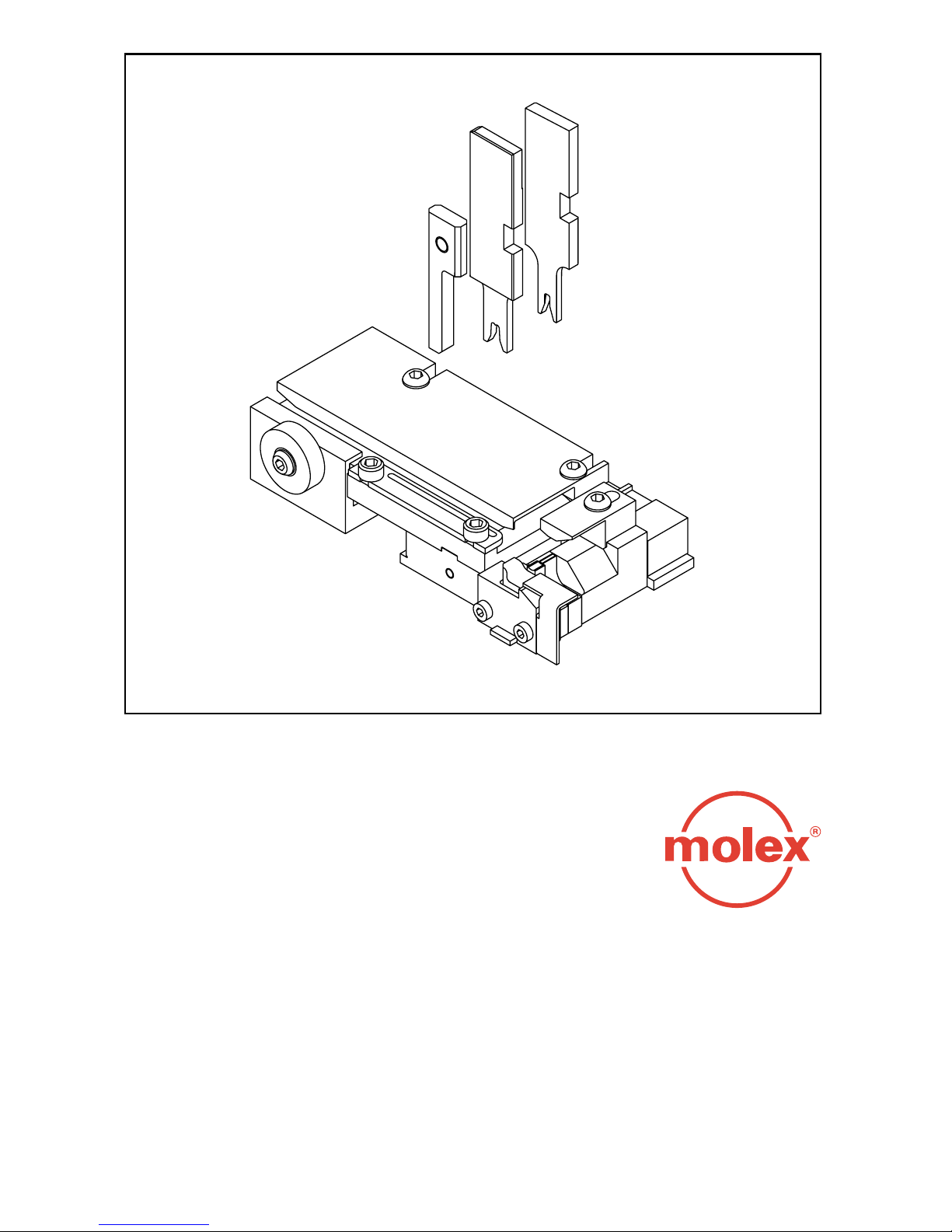
Molex Terminator
Description • Operation • Maintenance
DOC No 638500090
Release Date 99/07/01
Revision A
Revision Date 99/07/01
Page 2

WARNING
NEVER USE THIS TERMINATOR IN A PRESS WITHOUT GUARDS OR SAFETY DEVICES THAT
ARE INTENDED TO PREVENT INJURY. THE TERMINATOR IS SUPPLIED WITHOUT
GUARDS. PLEASE USE GUARDS SUPPLIED WITH THE PRESS. RUNNING THE PRESS
WITHOUT GUARDS UNDER ANY CIRCUMSTANCES CAN CAUSE SERIOUS INJURY.
NEVER INSTALL, OPERATE ADJUST, OR SERVICE THIS TERMINATOR WITHOUT PROPER IN-
STRUCTION AND WITHOUT FIRST READING AND UNDERSTANDING THE INSTRUCTIONS IN THIS MANUAL AND THE TM42 PRESS, TM40 PRESS, OR 3BF WITH BASE
UNIT ADAPTER MANUALS.
NEVER INSTALL, REMOVE OR SERVICE TERMINATOR TOOLING WHILE THE FLYWHEEL IS IN
MOTION OR POWER CONNECTED TO THE PRESS.
NEVER INSTALL, REMOVE OR SERVICE THE TERMINATOR TOOLING WITHOUT MANUALLY
CYCLING THE PRESS TO VERIFY THAT THE CLUTCH CONTROL IS IN THE LOCKED POSITION PAST TOP DEAD CENTER, BLOCK THE RAM IN THE UP POSITION IF A DEFECTIVE CLUTCH IS SUSPECTED.
CAUTION THE PRESS SHOULD ALWAYS BE HAND CYCLED WITH THE TERMINATOR INSTALLED
PRIOR TO RUNNING PRODUCTION. THIS PROCEDURE WILL PREVENT DAMAGE OR
REDUCE TOOL WEAR.
WORK SAFELY AT ALL TIMES
FOR SERVICE
CONTACT YOUR LOCAL SALES OFFICE
APPLICATION TOOLING GROUP
1150 DIEHL ROAD,
NAPERVILLE, ILLINOIS 60563
PH: (630) 969-4550
FAX: (630) 505-0049
3
Page 3

Molex Terminator
Table of Contents
Section
1. General Description
2. Installation - Setup - Operation
3. Maintenance
Appendix
A. Terminator Types & T2 Assembly Drawing
B. Crimp Definitions
C. Statistical Process Control (Summary)
5
Page 4

SECTION 1
General Description
Page
1.1 Description. . . . . . . . . . . . . . . . . . . . . . . . . . . . . . . . . . . . . . . . . . . . . . . . . . . . . . . . . . . . . . . . . . . 9
1.2 Features . . . . . . . . . . . . . . . . . . . . . . . . . . . . . . . . . . . . . . . . . . . . . . . . . . . . . . . . . . . . . . . . . . . . 9
1.3 Technical Specifications. . . . . . . . . . . . . . . . . . . . . . . . . . . . . . . . . . . . . . . . . . . . . . . . . . . . . . . . . . 9
1.4 Delivery Check. . . . . . . . . . . . . . . . . . . . . . . . . . . . . . . . . . . . . . . . . . . . . . . . . . . . . . . . . . . . . . . 10
1.5 Tools . . . . . . . . . . . . . . . . . . . . . . . . . . . . . . . . . . . . . . . . . . . . . . . . . . . . . . . . . . . . . . . . . . . . . . .10
1.6 Safety & Work Area Check . . . . . . . . . . . . . . . . . . . . . . . . . . . . . . . . . . . . . . . . . . . . . . . . . . . . . . .10
7
Page 5
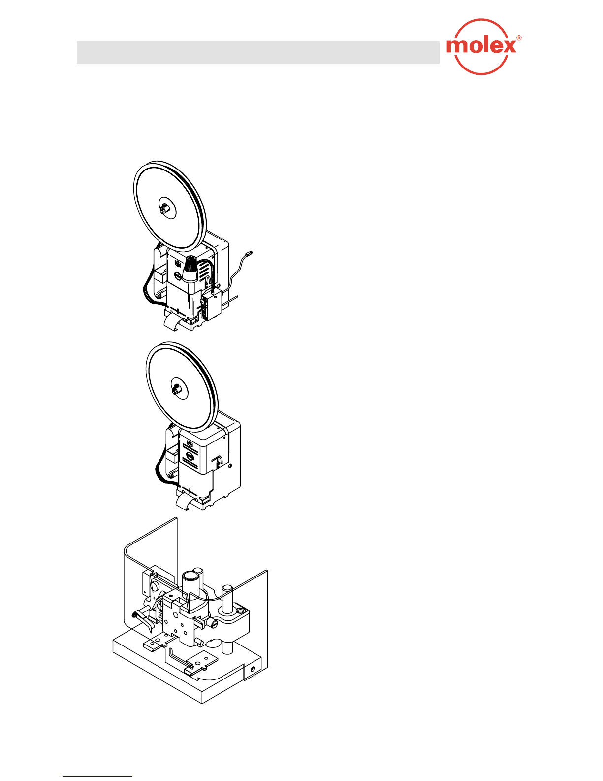
Molex Presses and Adapters
For “T” or “T2” Style Terminators
TM42 Press
ISO Metric.
■
Flexible external light.
■
Resettable counter.
■
1.5” Stroke.
■
TM40 Press
Internal Light.
■
Non resettable counter.
■
1.0” Stroke.
■
Base Unit Adapter
Allows 3BF press to run Terminator style tooling.
■
8
Page 6

General Description
1.1 Description
The Molex Terminator is an easy to use tool for the termination of a variety of Molex crimp terminals.
Production flexibility is obtained through the use of simple interchangeable tooling. The tooling is
inexpensive, and unlike a modular applicator, all crimp height and terminal feed adjustments are located
in the press. The terminator die can be installed in the TM42, TM40 presses or Base Unit adaptor, and is
ideally suited for mid-volume bench operation.
The Molex T2 terminator is the newer version tool that allows for track adjustment. It contains the identical
perishable tooling as the Molex FineAdjust applicator. (Center carrier excluded)
1.2 Features
■
Flexible and inexpensive.
■
Enhanced crimping productivity.
■
Simple installation.
■
Quick release punches.
■
T2 terminator has standardized tooling with Molex FineAdjust Applicator.
■
Track Adjustment capabilities in the T2 terminators for improved control of the bellmouth size and cutoff
tab length.
1.3 Technical Specifications
Dimensions
Width - 127.0 mm (5.0”)
Depth - 44.0 mm (1.8”)
Height - 25.0 mm (1”)
Weight - 1.4 kg (3.0 lbs)
9
Page 7

1.4 Delivery Check
Terminator 1
Sample crimped terminals 5
Manual 1
Setup & Specification Documents 1
1.5 Tools
The following tools are recommended for setup and adjustments of the terminator tool.
1. Metric Allen Set
2. English Allen Set (for older terminator tools)
3. Large and Small Screwdriver
4. Cresent Wrench
5. Pliers (needle nose)
6. Crimp Micrometer
7. Eye Loop (10x)
8. Wire Stripper/Cutter
Qty
1.6 Safety & Work Area Check
Check that the crimping position is ergonomic for the
operator’s size. A bench height of 762 to 813 mm (30
to 32 inches) will provide operator comfort, and allow
both feet to rest on the ground. The foot pedal should
be positioned for ease of reach.
Check that the press position is located paralleled and
approximately 150 mm (6 inches) from the edge of the
table. A chair or stool, with adjustable height and
backrest should be provided for maximum comfort and
back support to the operator. Adjust press light to give
appropriate visibility to the work area.
Check that the operators and observers are wearing
approved safety goggles when the press is in operation
and/or service.
10
Page 8

SECTION 2
Setup And Operation
Page
2.1 Terminator Die Installation and Removal. . . . . . . . . . . . . . . . . . . . . . . . . . . . . . . . . . . . . . . . . . . . . 13
2.2 Loading the Terminal Strip . . . . . . . . . . . . . . . . . . . . . . . . . . . . . . . . . . . . . . . . . . . . . . . . . . . . . . . 15
2.3 Manually Cycling the Press. . . . . . . . . . . . . . . . . . . . . . . . . . . . . . . . . . . . . . . . . . . . . . . . . . . . . . . 17
2.4 Punch and Anvil Alignment. . . . . . . . . . . . . . . . . . . . . . . . . . . . . . . . . . . . . . . . . . . . . . . . . . . . . . . 19
2.5 Feed Finger Location . . . . . . . . . . . . . . . . . . . . . . . . . . . . . . . . . . . . . . . . . . . . . . . . . . . . . . . . . . . 21
2.6 Forward and Back Feed Adjustment . . . . . . . . . . . . . . . . . . . . . . . . . . . . . . . . . . . . . . . . . . . . . . . . 23
2.7 Conductor Crimp Adjustment. . . . . . . . . . . . . . . . . . . . . . . . . . . . . . . . . . . . . . . . . . . . . . . . . . . . . . 25
2.8 Insulation Crimp Adjustment. . . . . . . . . . . . . . . . . . . . . . . . . . . . . . . . . . . . . . . . . . . . . . . . . . . . . . 27
2.9 Final Check and Operation . . . . . . . . . . . . . . . . . . . . . . . . . . . . . . . . . . . . . . . . . . . . . . . . . . . . . . . 29
11
Page 9
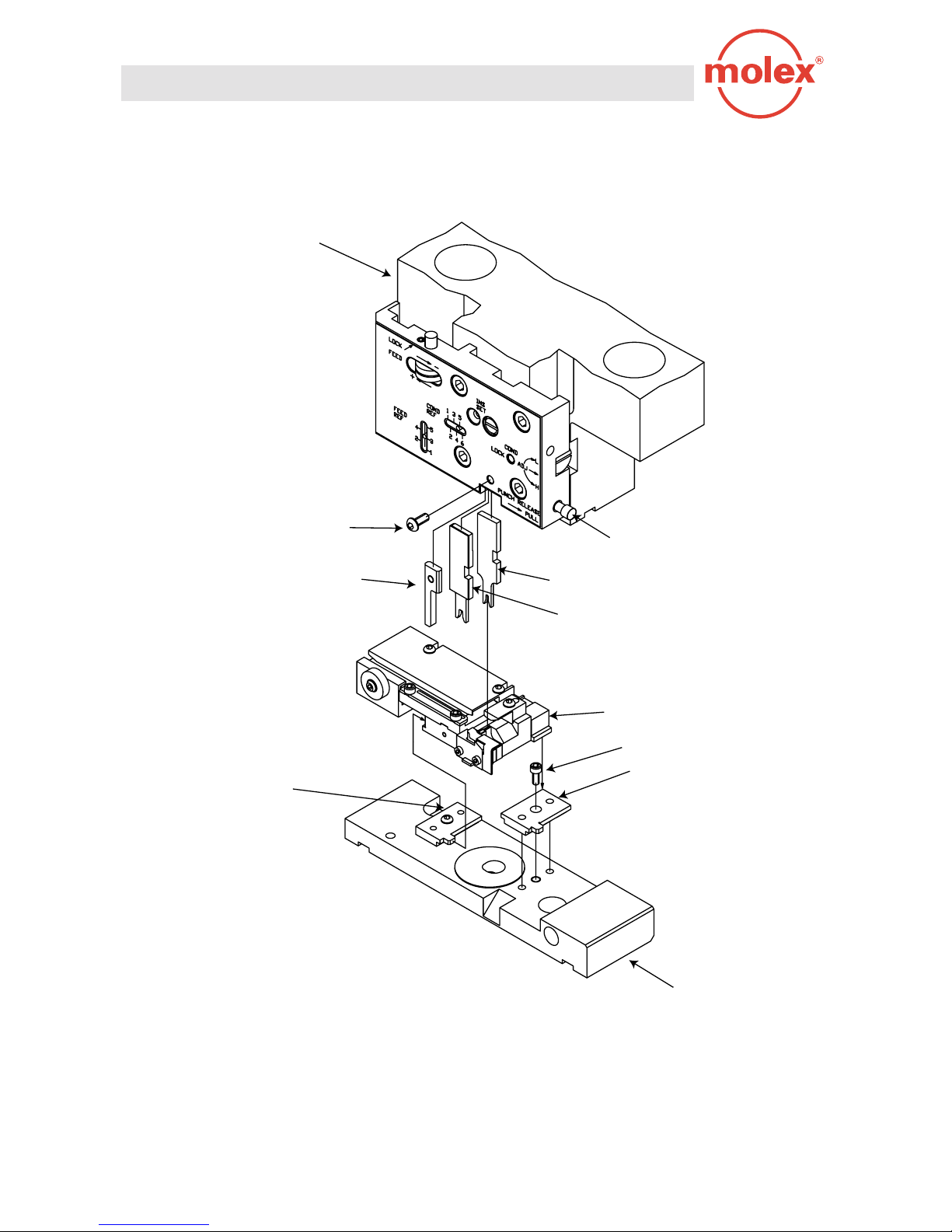
Ram
10-32 x 3/8 Lg. B.H.C.S.
Front Striker
Left Locating Plate
Punch Release Pin
Conductor Punch
Insulation Punch
T2 Terminator Base
M6 x 20 Lg. S.H.C.S.
Right Locating Plate
12
Bolster
TERMINATOR INSTALLATION
Fig. 1
Page 10

Terminator Die Installation & Removal
CAUTION
Always power down the press when installing or removing Molex tooling by pressing the emergency stop button located on
the front panel.
STEPS
(Ref. Fig. 1)
1. Remove Press guard. (Ref. Press or Base Unit manual.)
2. Confirm that the Terminator is correct for the specified product. (Ref. Specification sheets supplied with the
Terminator.)
3. Make sure all the tooling from a previous setup is removed. (See Step 11.)
4. Load all top tooling first, starting with the rear striker. (See Fig. 16.)
5. Pull on punch release pin to install punches into the punch cavity.
6. Finish with front striker (if specified). Confirm that all components follow assembly drawing sequence.
7. Clean bolster plate of scrap or chips that may interfere with the Terminator base installation.
8. Remove 6 mm S.H.C.S (TM42) and lift the right locating plate from the bolster.
9. Place the Terminator base on the bolster plate and slide to the left. The slot in the base will locate on the
left guide block
10. Replace the right locating plate and tighten 6 mm screw.
11. To remove the Terminator reverse the above steps.
13
Page 11
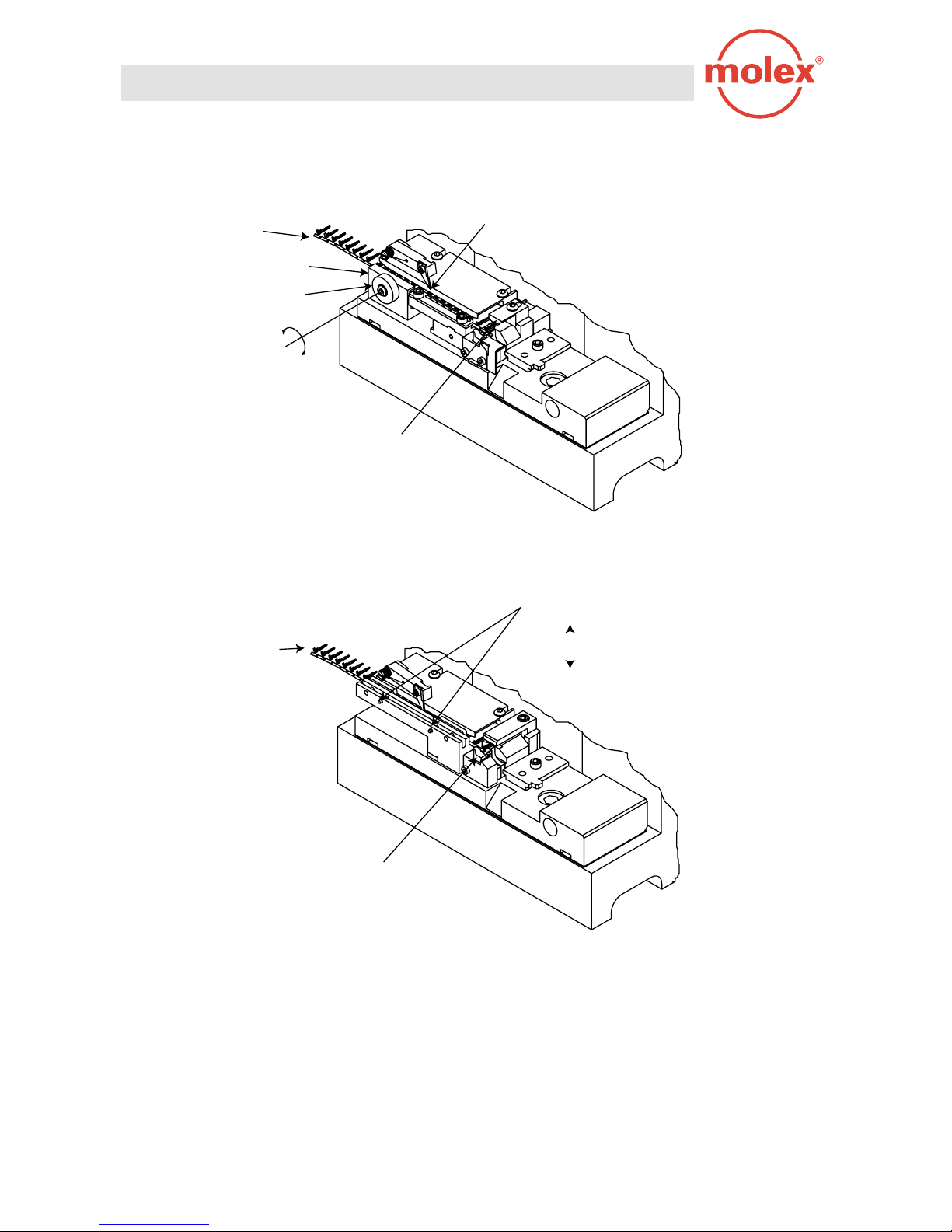
Terminal Strip Feeding
Drag Frame
Drag Cam
Rotate Drag Cam
Either Direction
to Raise or to Lower
Drag Frame
Lift the Feed Finger Up
First Terminal
Above Anvils
"T2" Style
Drag Finger / Anti-Back Up Finger
Terminal Strip Feeding
Lift up to Feed Terminal Strip
Release to Apply Drag on Terminal Strip
First Terminal
Above Anvils
"T" Style
LOADING THE TERMINAL STRIP
Fig. 2
14
Page 12

Loading The Terminal Strip
Note
Terminator Drag mechanism may vary on product selection or Terminator type.
Steps
(Ref. Fig. 2)
1. Confirm terminal part number matches the terminator specification sheet.
2. Install the terminal reel on the press reel holder.
3. Raise the drag plate (T2) and slide the terminal strip under both the cover plate and the drag plate.
4. For other “T” style Terminators, raise the drag finger and anti backup finger.
5. Ease the terminal strip forward until the first terminal on the strip is sitting on the anvils.
6. If severe resistance is encountered or the terminal strip does not fit, you may need to make a cover plate
adjustment.
Removing The Terminal Strip
Steps
1. Raise Terminal Drag plate or “T” style drag finger and anti backup finger.
2. Lift the Feed Finger from the carrier strip
3. Gently pull on the terminal strip until it has exited the track.
15
Page 13

Manual Cycle Clutch Release
16
Manually Cycling
HAND CYCLING
Fig. 3
Page 14

Manually Cycling the Press
Note
Hand cycling is necessary to confirm correct tool alignment, terminal feed adjustment, and also to give the setup
person the ability to step through the press cycle manually.
Steps
(Ref. Fig. 3)
1. Always power down the press by pressing the emergency stop button on the front control panel.
2. Release the clutch by inserting a screwdriver through the access hole to trip the locked actuator.
3. Insert the 10 mm hex wrench supplied with the press through the hole in the center of the rear cover and
engage it in the 12 mm S.H.C.S.
4. Rotate the press flywheel to move the ram as desired.
WARNING
When the actuator is disengaged, the ram is free to drop. Due to the weight of
the ram it is possible for the ram to start a downward movement.
Care must be taken to insure that the area in front of the press is clear of fingers
and hand tools.
The guards should be in place or the ram blocked.
Never insert anything through the press guards while the flywheel is in motion.
17
Page 15

Terminal in Position
over the Anvils
Anvil Mounting Screws
Hex Wrench
M4 x 20 Lg. S.H.C.S.
M4 X 50 Lg. S.H.C.S.
Press Ram at Bottom
of Full Down Stroke
Conductor Punch
Insulation Punch
Conductor Anvil
Insulation Avil
18
PUNCH & ANVIL ALIGNMENT
Fig. 4
Page 16

Punch and Anvil Alignment
Note
Correct punch and anvil alignment will insure quality crimps and excellent tool life.
Steps
(Ref. Fig. 4)
1. Slightly loosen the anvil mounting screws.
2. Place the hand cycling wrench through the hole in the center of the rear cover.
3. Gently lower the press ram until it is in the fully down position, with a terminal sitting on the the anvils the
punch will align the bottom tooling.
4. With the ram in the fully down position tighten the anvil mounting screws.
5. Bring the ram back to top dead center insuring that the clutch collar is engaged by the actuator.
6. Repeat the hand cycling operation to confirm alignment.
19
Page 17

Feed Finger Location
Feed Finger Location
Feed Finger Location
Feed Finger Location
Dual Carrier
End Carrier
Nose Carrier
Feed Finger Location
20
Center Carrier
Center Carrier
FEED FINGER LOCATION
Fig. 5
Page 18

Feed Finger Location Adjustment
Note
Feed finger location will vary depending on product selections see the feed finger location chart. (Ref. Fig. 5)
Steps
(Ref. Fig. 5.1)
1. Select feed finger position.
2. Loosen the feed finger shaft locking screw and position the feed finger in the selected position.
3. With a small screwdriver or 6" scale rotate the feed finger shaft to increase the spring pressure on the feed
finger.
4. While maintaining the spring pressure on the feed finger, tighten the feed finger locking screw.
Hex Wrench
Feed Lever
Feed Finger Shaft
Torsion Spring
Decrease
Increase
To Shaft Locking Screw
Feed Arm
Feed Finger
FEED FINGER SPRING ADJUSTMENT
Fig. 5.1
21
Page 19

Forward Feed Adjustment Lock Screw
Forward Feed
Adjustment Lock Wheel
Adjusting Backward
+
Adjusting Forward
Forward Feed Adjustment Indicator
1
Min. Backward Feed
5
Max. Forward Feed
Backward
M6 Jam Nut and
Fine Adjust Screw
Forward
Feed Finger
22
FORWARD AND BACKFEED ADJUSTMENT
Fig. 6
Page 20

Forward and Back Feed Adjustment
Note
Because of different terminal progressions, feed adjustment may be necessary.
Steps
(Ref. Fig. 6)
1. Make sure the press ram is in the fully up position and the clutch collar is engaged by the actuator.
2. Slide the terminal carrier strip all the way forward until it is centered over the anvils.
3. See the feed finger location (Fig. 5) for feed finger position.
4. Rotate the feed finger shaft with small screwdriver or 6” scale to get desired feed finger spring pressure
and tighten shaft locking screw.
5. Loosen 6 mm feed adjustment wheel locking screw.
6. Turn the feed adjustment wheel if necessary to position the terminal over the anvils.
7. Place the 10 mm hex head Allen wrench in the 12 mm S.H.C.S. located in the back of the press and slowly
hand cycle the press to the fully down position.
8. The feed finger should start to move backward one progression, if not loosen the 6 mm jam nut and back
the set screw out enabling the feed finger to move to the next pick up point.
9. If the feed finger is moving back more than one progression rotate the 6 mm set screw clockwise until the
feed finger is in the correct pickup point.
10. Hand cycle the press ram a few times and if necessary make the appropriate adjustments.
11. Tighten M6 lock nut and 6 mm feed adjustment locking screw.
23
Page 21

Conductor Adjustment Indicator
1
Setting (Loosest)
6
Setting (Tightest)
Lower Crimp Height
Higher Crimp Height
Conductor Adjustment Lock Screw
CONDUCTOR HEIGHT ADJUSTMENT
Conductor
Adjustment
Screw
Fig. 7
24
Page 22

Conductor Height Adjustment
Note
It is desirable to adjust the conductor adjustment wheel all the way to (1) on the conductor adjustment indicator, to
avoid punch crash prior to beginning this process.
Steps
(Ref. Fig. 7)
1. Replace the press guard.
2. Prepare wire for crimping. The selected wire should meet the parameters on the specification sheet.
3. Make sure that the 10 mm hex head Allen wrench is removed from the back of the press.
4. Turn the power on.
5. Place the wire through the slot in the press guard and all the way to the Terminator wire stop.
6. Activate the foot pedal, sweeping the crimped wire to the right.
7. Measure the crimped wire and verify desired crimp height on the specification sheet.
8. If crimp height adjustments are required, power down the press and remove the press guard.
9. Loosen the 6 mm crimp height locking screw and rotate conductor adjusting screw. Rotating the conductor
adjusting screw clockwise one full turn will tighten the crimp height approximately 0.03mm (.001”).
10. Repeat steps 1 thru 9 until the correct crimp height is achieved.
11. When correct crimp height is achieved tighten 6 mm lock screw.
12. Replace the press guard.
25
Page 23

Insulation Adjustment Indicator
1
Setting (Loosest)
8
Setting (Tightest)
Lower Crimp Height
Insulation Adjustment Cam
Higher Crimp Height
26
INSULATION CRIMP ADJUSTMENT
Fig. 8
Page 24

Insulation Crimp Adjustment
Note
The insulation crimp provides strain relief for the conductor crimp. The quality of the insulation crimp will depend
on the insulation diameter and durometer. Refer to the specification sheet for insulation diameter parameters.
Steps
(Ref. Fig. 8)
1. Place a stripped wire against the wire stop, crimp it under power.
2. Inspect the sample to determine if adjustments are needed.
3. If adjustments are needed powers down the press by pressing the emergency stop the button located in the
front of the control panel.
4. Remove the press guard.
5. Rotate the insulation adjusting cam to obtain the required insulation wrap.
6. Rotate the insulation adjusting cam, counter clockwise to tighten the insulation wrap.
7. Each increment represents approximately 0.1mm (.004).
8. Beginning at # 1 (loosest) to # 8 (tightest) insulation crimp.
9. Replace the press guard.
10. Repeat the above steps until the desired insulation crimp is obtained.
27
Page 25

28
OPERATION
Fig. 9
Page 26

Operation
Note
Check that all setup procedures were followed and all locking screws have been tightened. Follow the safety and
work area instructions.
Steps
(Ref. Fig. 9)
1. Press guard should be in position.
2. Wire should be pre stripped and prepared for crimping.
3. Place pre stripped wire through the slot in the press guard.
4. Touch pre-stripped wire against the wire stop.
5. Press foot pedal down once.
6. Use sweeping motion to the right with the crimped wire.
7. Check the crimped wire and confirm that it meets the Terminator specifications and visual inspection.
29
Page 27

SECTION 3
Maintenance
Note
Terminator maintenance will increase tool life and produce a consistent, reliable quality crimp. The following
procedure should be followed at the end of each operation.
Steps
1. Power down the press.
2. Remove the press guard.
3. Make sure that the clutch collar is engaged by the clutch actuator.
4. Take a small brush and clean in and around the terminator anvils.
5. Inspect perishable tooling for wear or fracture.
Molex recommends that you maintain a spare tooling kit at your facility.
The Terminator should be free of all carrier strip tabs and plating that may have accumulated during
production.
30
Page 28

Terminator Types
Note
Molex supplies different types of Terminators depending on the vintage. The following illustrations are a generic
guide to the Tool that you may have.
1. Track Adjustment. . . . . . . . . . . . . . . . . . . . . . . . . . . .Fig. 10
2. End carrier T2 . . . . . . . . . . . . . . . . . . . . . . . . . . . . . .Fig. 11
3. Dual carrier T2. . . . . . . . . . . . . . . . . . . . . . . . . . . . . .Fig. 12
4. Center carrier “T”. . . . . . . . . . . . . . . . . . . . . . . . . . . .Fig. 13
5. Micro terminal “T”. . . . . . . . . . . . . . . . . . . . . . . . . . .Fig. 14
6. T2 Terminator Assembly. . . . . . . . . . . . . . . . . . . . . . .Fig. 15
7. Rear Striker Installation . . . . . . . . . . . . . . . . . . . . . . .Fig. 16
31
Page 29

T2 Terminator
Track Adjustment Front
Track Adjustment Back
T2 Terminator
Base
Terminal Track
M5 x 10 Lg. S.H.C.S.
T2 TERMINATOR
Fig. 10
Track Adjustment T2 Series
The T2 Terminator allows for adjustment of both the bellmouth and cut-off tab by loosening the 6 mm S.H.C.S and
moving the terminator track in or out to achive desired conditions on crimp.
32
Page 30

Insulation
Punch
Conductor
Punch
Rear Cover
Front
Plunger
Striker
Front Cut-Off
Plunger
Cut-Off
Plunger
Spring
Plunger
Retainer
Conductor
Anvil
Insulation
Anvil
Front Cover
Track
Base
Wire Stop
Anvil Mount
Tooling Key
Scrap Deflector
T2 END CARRIER (GENERIC)
Fig. 11
33
Page 31

Front
Plunger
Striker
Insulation
Punch
Punch
Hold Down
Spring
Hold Down
ShaftConductor
Rear
Striker
Rear Cut-Off
Plunger
Cut-Off
Plunger
Spring
Front
Cover
Rear Cover
Wire
Stop
Base
Track
Front Cut-Off
Plunger
Cut-Off
Plunger
Spring
Front
Plunger
Retainer
Cut-Off
Blade
Rear Spacer
Rear Plunger Retainer
Tooling Key
Front Spacer
Conductor Anvil
Insulation Anvil
T2 DUAL CARRIER (GENERIC)
Fig. 12
34
Page 32

Carrier Hold Down
Hold Down Spring
Hold Down Plunger
Cut-Off Punch
Conductor Punch
Stop Finger Torsion Spring
Cover Plate
Stop finger
Spiral Pin
Insulation Punch
Rear Cut-Off Die
Pivot Pin
Cover Mounting Screw
Cover Guiding Pin
Front Cover
Wire Stop
Track
Tooling Mounting Screw
Spacer
Front Cut-Off Die
& Anvil Combination
T” STYLE CENTER CARRIER (GENERIC)
Fig. 13
35
Page 33

Front Cover
Rear Cover
Conductor Punch
Insulation
Punch
Plunger
Striker
Adjusting Screw
Pin Lock
Adjusting Screw
Plunger
Retainer
Tooling
Mounting
Screw
Track
Adjustor Bar
Wire Stop
Bracket
Wire
Stop
Base
Anvil Mounting Block
Combination Anvil
Cut-Off Plunger
Cut-Off Plunger Spring
36
Spring Plate
MICRO TERMINAL (GENERIC)
Fig. 14
Page 34

2
3
1
5
6
7
8
4
T2 Terminator Bill of Materials
Item No. Order No. Description Qty.
1 638008501 T2 Terminator Base 1
2 638000108 Terminal Track 1
3 690280660 Drag Springs 2
4 638000316 Guide Pin-Drag Frame 2
5 638000312 Drag Frame 1
6 638000115 Spacer Tube 1
7 638000313 Drag Cam 1
8 M4 x 12 Lg. B.H.C.S. 1
9 M5 x 10 Lg. S.H.C.S. 1
9
T2 TERMINATOR ASSEMBLY
Fig. 15
37
Page 35

Hold Down Plunger Set Screw
Hold Down Spring
Hold Down Plunger
REAR STRIKER INSTALLATION
Rear Striker
Rear Striker Mounting Screw
Fig. 16
38
Page 36

Crimp Terminations
40
Page 37

Definitions
Anatomy Of A Crimp Termination
Bellmouth ( Flare)
The flare that is formed on the edge of the conductor crimp acts as a funnel for the wire strands. The funnel reduces
the possibility that a sharp edge on the conductor crimp will cut or nick the wire strands.
Bend Up /Bend Down /Twisting / Rolling
The terminal bending up, bending down, twisting or rolling indicates that the nose of the terminal is reacting to the
crimping process
Brush
The conductor brush is made up of wire strands that extend past the conductor crimp.
Conductor Crimp
This is the metallurgical compression of a terminal around the wire’s conductor.
Crimp Height
The conductor crimp height is measured from the top surface of the formed crimp to the bottom most radial surface.
Cut-Off Tab Length
This is the material that protrudes outside the insulation crimp after the terminal is separated from the carrier strip.
Insulation Crimp
The insulation crimp provides a strain relief for the crimped wire and support for insertion into the housing.
Strip Length
The strip length is the pre determined amount of bare wire that is exposed for crimping.
41
Page 38

Statistical Process Control (Summary)
Process Confirmation.
Molex recommends that prior to production, a 25 piece process capability study on both crimp height and pull force.
Setup/Visual Inspection
Minimum 5 piece sample should be checked for crimp height per specification sheet.
Visually check bellmouth, conductor brush, insulation position, cutoff tab length and insulation crimp to specification
sheet guidelines for optimum setup.
Production
Visual check every bundle by fanning the crimped wires.
Check crimp height every 250- 500 pieces.
Molex recommends control charting of crimp heights for long production runs.
Example Control Chart
Contol Limit for sample of 5 = Avg (Avg of 5 readings) + .577 x Avg (Ranges)
X & R Chart
Note
: For more detail information please refer to the Molex Quality Crimping Handbook, Order No. 63800-0029.
42
Page 39

Terminator Crimping Manual
Corporate Headquarters
2222 Wellington Court
Lisle, IL, 60532, U.S.A
Tel : 630-969-4550
Application Tooling Division
1150 E. Diehl Rd
Naperville, IL, 60563
Tel : 630-969-4550
European Headquarters
Munich, Germany
Tel : 49-89-413092-0
Printed in U.S.A 1999 Molex Incorporated
Order Number - 638500090
Far East North Headquarters
Kanagawa, Japan
Tel : 81-462-2324
Far East South Headquarters
Jurong Town, Singapore
Tel : 65-268-6868
 Loading...