

Page 1

TM-3000 and TM-4000 Universal Press
Use with Molex FineAdjust, Mini-Mac Applicators and the Molex
Description
Operation
Maintenance
Order No: TM-638017299 Release Date: 06-06-05 UNCONTROLLED COPY Page 1 of 47
Revision: D Revision Date: 12-0-02-09
TM-3000 UNIVERSAL PRESS
TM-4000 UNIVERSAL PRESS
Tape Terminal Crimp Module
Instruction Manual
Order No.63801-7299
Page 2

TM-3000 and TM-4000 Universal Press
WARNING
NEVER USE THIS MACHINE WITHOUT THE GUARDS OR SAFETY DEVICES THAT ARE INTENDED TO
PREVENT HANDS FROM REMAINING IN THE DIE SPACE. RUNNING THIS MACHINE WITHOUT
GUARDS, UNDER ANY CIRCUMSTANCES, CAN CAUSE SERIOUS INJURY.
NEVER LIFT THIS PRESS WITHOUT THE AID OF MECHANICAL LIFTING DEVICES.
NEVER OPERATE, SERVICE, OR ADJUST THIS MACHINE OR INSTALL APPLICATOR DIES WITHOUT
PROPER INSTRUCTION AND WITHOUT FIRST READING AND UNDERSTANDING THE
INSTRUCTIONS IN THIS MANUAL.
NEVER SERVICE THIS MACHINE WHILE IT IS CONNECTED TO ANY ELECTRICAL POWER SOURCE.
DISCONNECT POWER BY UNPLUGGING THE PRESS FROM ITS POWER SOURCE AND FROM
THE COMPRESSED AIR SUPPLY.
NEVER INSTALL OR REMOVE APPLICATOR DIES WITH THE MOTOR RUNNING, OR AIR SUPPLY
CONNECTED.
CAUTION THIS PRESS IS SHIPPED FROM THE FACTORY AT A SHUT HEIGHT OF 135.80mm (5.346”).
FAILURE TO HAND CYCLE THE PRESS WHEN INSTALLING APPLICATORS CAN CAUSE
SEVERE DAMAGE TO THE TOOLING AND/OR PRESS.
CAUTION MOLEX CRIMP SPECIFICATIONS ARE VALID ONLY WHEN USED WITH MOLEX TERMINALS,
APPLICATORS AND TOOLING.
WORK SAFELY AT ALL TIMES
Order No: TM-638017299 Release Date: 06-06-05 UNCONTROLLED COPY Page 2 of 47
Revision: D Revision Date: 12-0-02-09
For Service, Contact Your
Local Molex Sales Office
Molex Application Tooling Group
2200 Wellington Court
Lisle, Illinois 60532
Tel: 630-969-4550
Fax: 630-505-0049
Page 3

TM-3000 and TM-4000 Universal Press
1 General Description
2 Installation
3 Setup - Operation
4 Maintenance and Troubleshooting
5 Parts List, Assembly Drawings, Electrical Schematics
6 EC Declaration of Conformity
A Options
1. Taped Terminal Crimp Module
Table of Contents
SECTION
APPENDIX
Order No: TM-638017299 Release Date: 06-06-05 UNCONTROLLED COPY Page 3 of 47
Revision: D Revision Date: 12-0-02-09
Page 4

TM-3000 and TM-4000 Universal Press
1.1 Description
1.2 Features
1.3 Technical Specifications
1.4 Delivery Check
1.5 Tools
Section 1
General Description
Order No: TM-638017299 Release Date: 06-06-05 UNCONTROLLED COPY Page 4 of 47
Revision: D Revision Date: 12-0-02-09
Page 5

TM-3000 and TM-4000 Universal Press
General Description
1.1 Description
The 63801-7200 (120V AC version), the 638017300 (240V AC version) TM-3000 Universal Press
and the 63801-7600 (240V AC version) TM-4000
Universal Press are economical, electricallyoperated, single-cycle and split cycle direct drive
presses. They are designed to provide an effective
method of applying a wide range of side-feed and
rear-feed terminals to a pre-stripped discrete wire or
cable. Both the TM-3000 and the TM-4000 are
suited to mid-volume semi-automatic operations.
Production flexibility is obtained using
interchangeable FineAdjust or Mini-Mac applicators
and most Industrial Standard Applicators.
These presses will complete one crimping cycle with
each depression of the foot pedal and two
depressions for split cycle. Safe operation is
provided by an interlock switch that renders the
press inoperative if the safety guard is opened or
removed.
1.2 Features
Utilizes both FineAdjust and Mini-Mac
applicators side and rear feed, and most
industry standard applicators
Press is shipped set to Industry shut height of
135.80mm (5.346”)
Ideal for mid-volume, semi-automatic
applications
Meets O.S.H.A. safety standards is ANSI-
Z535.2-2002 compliant
Totally enclosed for operator safety, including a
power interlock switch for the front guard
Resettable counter for accurate batch counting
Modular solid state controls with an easy plug in
power cord and foot switch.
“CE” Certified
1.3 Technical Specifications
Dimensions with reel mounted
Height 1210mm (47.60“)
Width 648mm (25.50“)
Depth 559mm (22.00“)
Unpacked weight 100kg (220 lb)
Power Requirements
Voltage: 63801-7200-120V AC 60 Hz
Voltage: 63801-7300-240V AC 50 – 60 Hz
Voltage: 63801-7600-240V AC 50 – 60 Hz
Note:
If 240V power is not available, then 120V power
may be used with an appropriate (1000VA
minimum) step-up transformer.
Recommended step-up transformer: Allied
Electronics #836-0181 (phone: 1-800-433-5700).
Pneumatic Requirements (Air Feed Applicators
only)
75 psi min. (366 kN/cm2) min.
1.0 SCFM (28.3 L/min)
¼” NPT inlet 12.7mm (1/2”) supply pipe minimum.
Production Rate
2400 terminations per hour maximum, depending
on operator skill and wire length.
Processing Capability
TM-3000 Press output = 4000 lbf (18kN).
Copper conductors up to 10 AWG (5.0mm²) in
solid or stranded wire.
TM-4000 Press output = 7000 lbf (31kN).
Copper conductors up to 4 AWG (21.0mm²) in
solid or stranded wire.
Sound Level
Operator will be exposed to less than 85 dBA.
1.4. Delivery Check
After removing the packaging band, the top and
sides of the box should lift off easily. The following
items are included in this package :
Quantity
Main Press Body 1
Reel Support Assembly 1
“T” wrench for manual cycling 1
Order No: TM-638017299 Release Date: 06-06-05 UNCONTROLLED COPY Page 5 of 47
Revision: D Revision Date: 12-0-02-09
Page 6

TM-3000 and TM-4000 Universal Press
Carton Contents Quantity
69018-6237 PowerCord
(for 63801-7200) 1
OR
62500-1774 Power Cord 220V 10A
(for 63801-7300 and 63801-7600) 1
63801-7271 Foot Pedal 1
TM-638007299 Instruction Manual 1
1.5 Tools
The following tools are recommended for setup
and adjustments to the applicator in this press
Metric hex wrench set
Small standard screwdriver
Adjustable wrench
Needle nose pliers
Crimp micrometer
Eye loupe (10x)
Wire stripper/cutter
English hex wrench set for some non-metric
applicators
Order No: TM-638017299 Release Date: 06-06-05 UNCONTROLLED COPY Page 6 of 47
Revision: D Revision Date: 12-0-02-09
Page 7

TM-3000 and TM-4000 Universal Press
2.1 Lifting/Mounting
2.2 Reel Support
2.3 Foot Pedal and Power Connection
2.4 Pneumatic Supply Hook-up
2.5 Terminal Feed Guide
2.6 Function Test
2.7 Safety and Work Area Check
Section 2
Installation
Order No: TM-638017299 Release Date: 06-06-05 UNCONTROLLED COPY Page 7 of 47
Revision: D Revision Date: 12-0-02-09
Page 8
TM-3000 and TM-4000 Universal Press
LIFT HOOK
TERMINAL GUIDE
POWER CORD
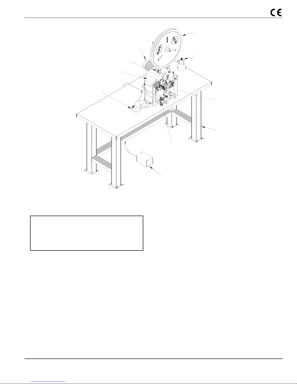
2.1 Lifting/Mounting
WARNING: This Press weighs over 100 kg (220
lb); it should not attempt to be lifted by one
individual. Mechanical lifting devices should be
used. A person lifting the press can sustain
severe back or other injuries.
A lifting hook is provided on the top of the press. A
heavy-duty chain, rope, cable, or belt can be used
with loops, links, or rings on each end that can
securely attach to the lifting hooks. An electric,
hydraulic, or mechanical crane should be used to
lift the press. Lift the press up approximately
12mm (.50”) and verify that the press is well
balanced. Upon verification, the press can be lifted
onto a sturdy workbench. Access to the back of
the machine is required for manual cycling. A
wooden bench that is a minimum of 25mm (1.00”)
thick will offer quiet vibration-free operation. For
thinner or sheet metal tops, the TM-3000 can be
MOTOR
REEL SUPPORT
ASSEMBLY
WORK LIGHT
PRESS CONTROL
ASSEMBLY
WORK BENCH
OILER ASSEMBLY
FOOT PEDAL
ASSEMBLY
Figure 2-1
attached to the table with two 12mm bolts. Bolts
are not supplied by Molex.
2.2 Reel Support
Install the reel support in the hole located on the top of
machine frame. For rear feed, rotate the reel support
as required. See Figure 2-3. Loosen the M10 set
screw that holds the reel support. Pull up from the
hole and rotate for the proper feeding orientation.
Then slide down back into the hole and tighten the
M10 set screw.
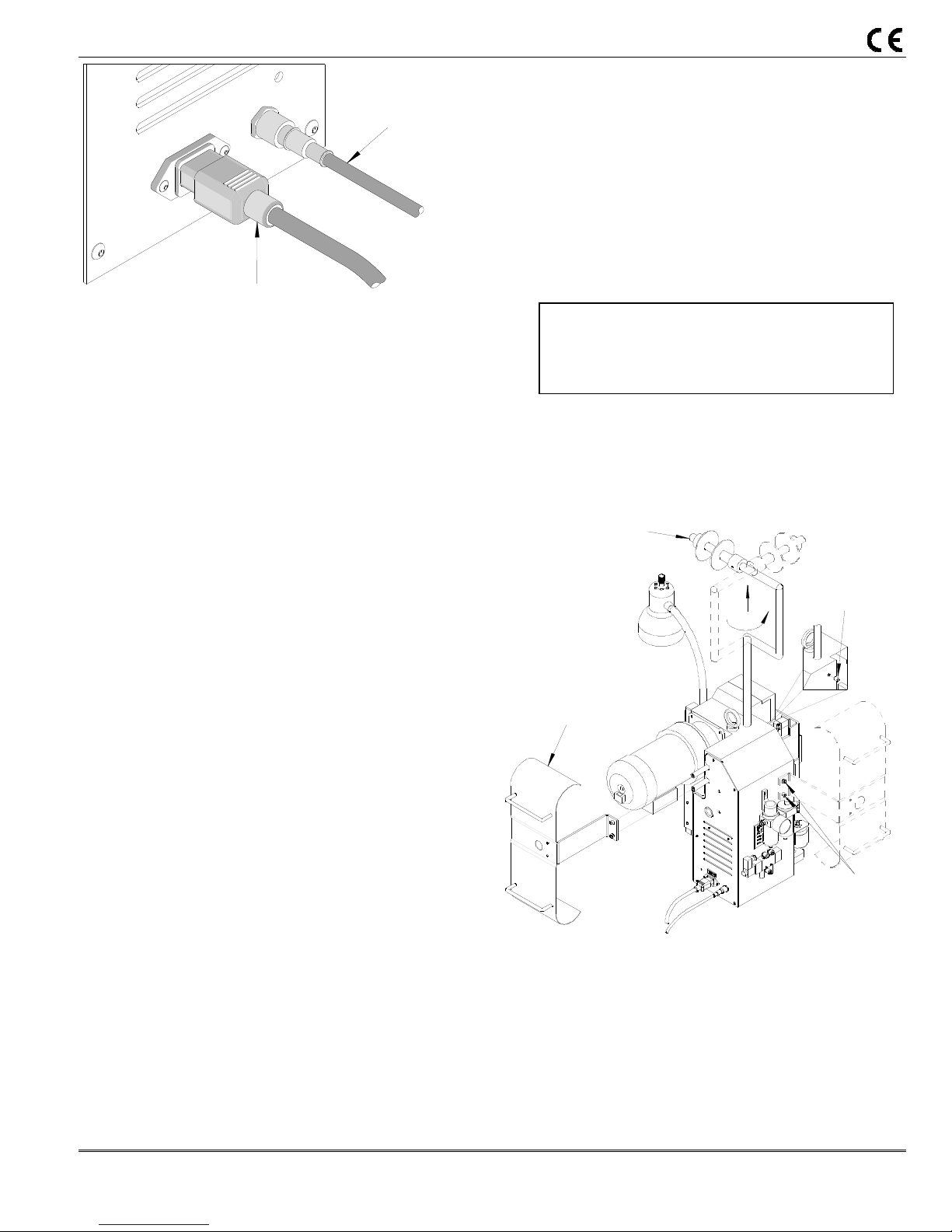
2.3 Foot Pedal and Power Connection
Connect the 3-pin plug for the foot pedal in the rear of
the press control assembly. Turn the locking ring
clockwise until tight. Connect the power cord plug to
the socket in the back of the control assembly. Use a
grounded electrical outlet as the power source. See
Figure 2-2.
Order No: TM-638017299 Release Date: 06-06-05 UNCONTROLLED COPY Page 8 of 47
Revision: D Revision Date: 12-0-02-09
Page 9
TM-3000 and TM-4000 Universal Press
FOOTSWITCH
CORD
Figure 2-2
POWER
CORD PLUG
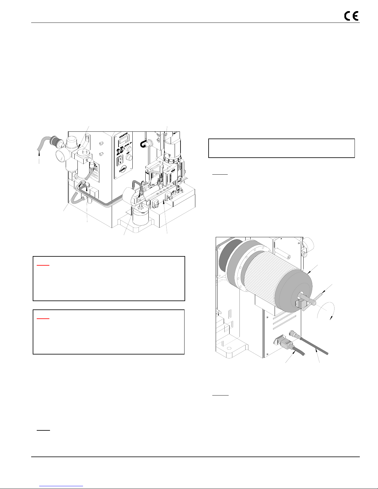
2.4 Pneumatic Supply Hook-Up
A compressed air supply is required if air feed or other
air powered applicators will be used. The press
comes equipped with an air supply system, which
consists of filter, regulator, lubricator and a valve to
actuate the air feeds at the proper time in the press
cycle.
Due to the considerable types of air connection and
quick connect fittings available; Molex only supplies
the press with a 1/4 NPT female threaded fitting. The
customer may attach whatever type of air connections
that are commonly used in their plant to this port.
The minimum flexible tube size used to connect the
press should be 8mm or 5/16” to assure adequate flow
rate.
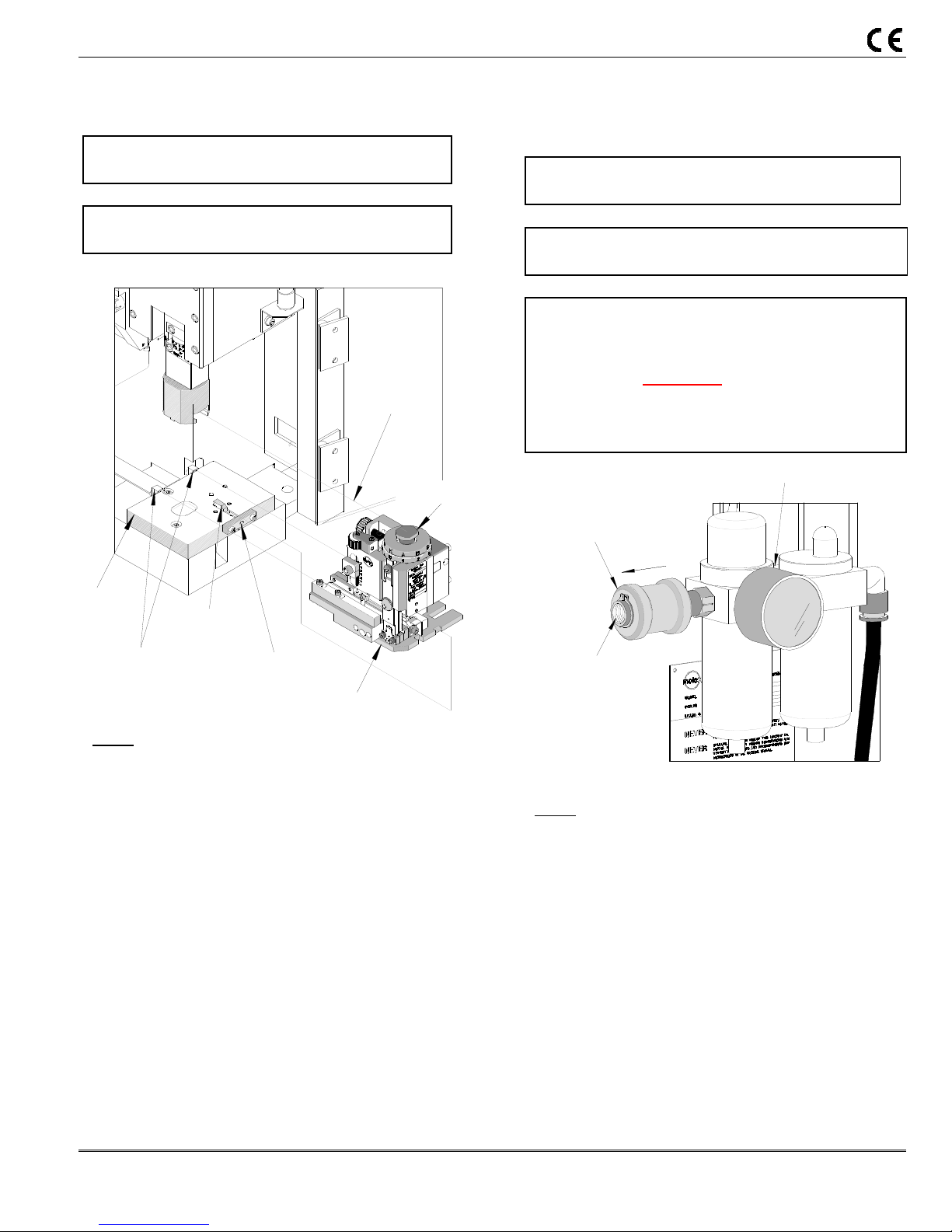
A filter-regulator-lubricator unit is supplied to properly
condition the incoming air. The filter will remove
particulate and moisture from the air that can damage
or reduce the life of cylinders and valves. This filter
and bowl should be serviced on a regular schedule.
(See section 4.1) The filter has an automatic drain at
the bottom of the bowl that will automatically open and
expel fluid when the bowl is getting full. It is
recommended that, a 6mm or 1/4” flexible tube, be
attached to the drain hose barb and run to a container
if the air system contains excessive moisture.
The regulator adjusts the pressure of the incoming air
to what the applicators require usually 60-80 PSI (refer
to the applicator manual for recommended pressures.)
Adjustment is accomplished by pulling up on the knob,
rotating it until the gauge indicates the desired
pressure, then pushing it down to lock the setting.
A lubricator is supplied for those applicator air feeds
that need lubrication. Molex air-feed applicators do
not require lubrication. The lubricator is shipped
without lubricant in it. To use, fill the lubricator (make
sure the main air supply is disconnected or that the
slide valve provided is in the off position before adding
lubricant) through the fill plug on the top of the unit,
with high quality SAE 10 W oil. The lubricator has a
graduated dial on top, turn the dial to the 1 or 2
setting.
Caution: Do not over lubricate. Only a very
small amount of lubricant is required to assure
smooth operation. Excess lubricant is exhausted
to the atmosphere.
If lubrication is not required set the dial to 0 to turn off
the lubricator.
2.5 Terminal Feed Guide
PULL UP FROM
HOLE, ROTATE AND
SLIDE DOWN INTO
HOLE
REPOSITION
TERMINAL GUIDE
Figure 2-3
Depending on side or rear-feed applications, the
terminal guide plate and bracket must be repositioned.
The press is set for side-feed applicators when
shipped from the factory. When rear-feed applicators
are used, the two M6 BHCS from the terminal guidemounting bracket are to be removed. See Figure 2-3.
The guide bracket is rotated 180 degrees and the
assembly is then mounted on the two standoffs in the
LOOSEN
M10 SSS IN
FRONT OF
PRESS
REMOVE M6 BHCS
AND REMOVE
TERMINAL GUIDE
Order No: TM-638017299 Release Date: 06-06-05 UNCONTROLLED COPY Page 9 of 47
Revision: D Revision Date: 12-0-02-09
Page 10
TM-3000 and TM-4000 Universal Press
rear of the press with the two M6 SHCS. See Figure
2-3.
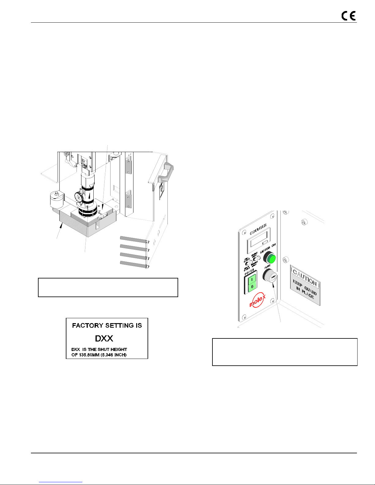
2.6 Function Test
When the press is shipped from the factory, it is set
to the industry shut height of 135.80 mm (5.346”) with
a calibrated load gauge. The press shut height
gauge is spring loaded to give an accurate reading
on the press shut height. See Figure 2-4. Molex
recommends hand cycling the press each time an
applicator is installed. See Section 3-3.
PRESS
SHUT HEIGHT GAUGE
CAUTION: Always manually cycle the press
before restoring power to the machine.
2.6.1 Verification of Press Shut Height
This press comes factory set at an Industry Standard
shut height of 135.80mm (5.346”). A label is
attached to the front of each press indicating the
factory settings. This press has an adjustable shut
height, see Section 3.4.3 for crimp height adjustment.
Always return the press to the factory setting on the
label before installing applicators to avoid tooling
PRESS QUICK CHANGE
MOUNTING PLATE
Figure 2-4
damage. Check the factory setting periodically with a
calibrated shut height gage.
Shut height gauges may be purchased from:
Artos Eng. 602-581-0070
Komax Corp. 847-537-6640
2.7 Safety and Work Area Check
Check that the crimping position is ergonomic
for the operator’s size. A bench height of 762.00
to 813.00mm (30.00 to 32.00”) will provide
operator comfort, and allows both feet to rest on
the floor. The foot pedal should be placed in a
comfortable position. Check that the press
position is located approximately 150mm (6“)
from the edge of the bench. A chair or stool with
adjustable height and backrest should be
provided for maximum comfort and back support
for the operator.
FUSE HOLDER
CAUTION: Molex recommends that the operator
and observers wear eye protection when the press
is in operation or being serviced.
The fuse is located on the control panel. To
replace the fuse (10AMP on 110 V models and
5AMP on 220V models), turn the holder in the
direction as shown. Turn clockwise to secure
holder in place when replaced. See Figure 2-5.
Figure 2-5
Order No: TM-638017299 Release Date: 06-06-05 UNCONTROLLED COPY Page 10 of 47
Revision: D Revision Date: 12-0-02-09
Page 11

TM-3000 and TM-4000 Universal Press
3.1 Applicator Installation
3.2 Air Feed Applicator Installation
3.3 Manually Cycling the Press
3.4 Operation
Section 3
Setup and Operation
Order No: TM-638017299 Release Date: 06-06-05 UNCONTROLLED COPY Page 11 of 47
Revision: D Revision Date: 12-0-02-09
Page 12
TM-3000 and TM-4000 Universal Press
3.1 Applicator Installation
Power down the press by turning off the “POWER”
switch located on the control panel.
Note: Once the press guard is open the guard
interlock switch will disconnect power to the motor.
QUICK
CHANGE
PLATE
LOCATOR
CLAMPS
LOCKING
CLAMP
HEX WRENCH
Figure 3-1
USE 4mm
BASE PLATE
Steps
1. Swing the press guard open.
2. Verify that the applicator is correctly tooled for
the terminal being used. (Reference
specification sheets supplied with the
applicator).
3. Clean the press quick change mounting plate of
scrap or chips that may interfere with the
applicator installation.
4. Using a 4mm hex wrench, turn the M5 SHCS
clockwise until the locking clamp is fully opened.
5. Locate the applicator lug bolt in the press yoke.
See Figure 3-1.
6. Align the applicator base plate slots with the
locator clamps on the press quick change plate.
7. To lock applicator, turn M5 SHCS counter
clockwise until tight.
8. Confirm that the applicator is secured properly.
ENGAGE
PRESS YOKE
LUG BOLT
3.2 Air Feed Applicator Installation
Power down the press by turning off the “POWER”
switch, located on the control panel.
Note: Once the press guard is open the guard
interlock switch will disconnect power to the motor.
Warning: When using air feed applicators, always
use the slide valve supplied to shut-off and vent air
pressure to the air feed before servicing. The guard
interlock switch DOES NOT remove air pressure. If
an air feed is jammed and air pressure is not
removed before servicing, the feed could move
unexpectedly and cause injury.
SHUT-OFF
SLEEVE
SLIDE LEFT TO
SHUT OFF
TO MAIN
AIR SUPPLY
Figure 3-2
Steps
1. Swing the press guard open.
2. Verify that the applicator is correctly tooled for the
terminal being used. (Reference specification
sheets supplied with the applicator).
3. Clean the press quick change mounting plate of
scrap or chips that may interfere with the
applicator installation.
4. Using a 4mm hex wrench, turn the M5 SHCS
clockwise until the locking clamp is fully opened.
5. Locate the applicator lug bolt in the press yoke.
See Figure 3-1.
6. Align the applicator base plate slots with the
locator clamps on the press quick change
mounting plate.
FILTER-REG-LUBRICATOR
Order No: TM-638017299 Release Date: 06-06-05 UNCONTROLLED COPY Page 12 of 47
Revision: D Revision Date: 12-0-02-09
Page 13
TM-3000 and TM-4000 Universal Press
7. To lock applicator, turn M5 SHCS counter
clockwise until tight.
8. Confirm that the applicator is secured properly.
9. Disconnect the air supply from the filter-regulatorlubricator supplied with the press, by sliding the
shutoff valve sleeve to the left, as shown in Figure
3-2. Remove the plugs from the fittings on the air
valve. Do not discard the plugs; when the air
applicator is not being used, the fittings should be
plugged.
FILTER-REG. LUBRICATOR
RETRACTS
TO MAIN
AIR SUPPLY
PORT ”A”
Figure 3-3
PORT ”B”
ADVANCES
APPLICATOR
Note: When not using an air feed applicator always
shutoff the air supply to the filter-regulator-lubricator
by sliding the shutoff valve sleeve to the left, the
opposite direction of the airflow, as shown in Figure
3-2.
Note: Some applicators feed terminals in the
retracted position, for those air tubes must be
reversed. In addition, some applicators are air
advance and spring return, on these applicators one
port will need to be plugged.
10. Insert the “A” port of the air valve with the tube
that retracts the feed mechanism of the applicator.
See Figure 3-3.
11. Insert the “B” port of the air valve with the tube
that advances the feed mechanism of the
applicator. See Figure 3-3.
Note: When using the 64016-2000 Crimp Module, set
the feed selector on the control panel to “SINGLE” or
AIR-FEED
“DOUBLE”, depending on the spacing of the taped
terminals. See Figure 3-5.
12. Connect the main air supply to the filter reglubricator. (Custumer supplied fitting)
13. Adjust the regulator to 75-80 PSI (366-390
kN/cm2).
14. Check that the tubing for the applicator is properly
connected by dry cycling the press and observing
the feed motion.
3.3. Manually Cycling the Press
Turn off the “POWER” switch which is located on
the control panel to power down the press.
Note: Once the press guard is open the guard
interlock switch will disconnect power to the motor.
Hand cycling the press is necessary to confirm
correct tool alignment and terminal feed
adjustment. It also gives the setup person the
ability to step through the press cycle manually.
Figure 3-4
POWER CORD
Steps
1. Insert the 8mm square socket T-handle wrench
through the access hole in the center of the rear
cover on the motor and locate it in the shaft motor.
See Figure 3-4.
MOTOR
T-HANDLE
WRENCH
TURN
CLOCKWISE
FOOT SWITCH
CORD
Order No: TM-638017299 Release Date: 06-06-05 UNCONTROLLED COPY Page 13 of 47
Revision: D Revision Date: 12-0-02-09
Page 14
TM-3000 and TM-4000 Universal Press
2. Rotate the wrench clockwise. This turns the motor
and moves the ram down and up.
3. Always return the press back to top dead center
insuring that the ram is in the start up position.
4. Remove the T-handle wrench.
NOTE: When the T-handle is put into the motor
shaft the motor turns off automatically.
3.4. Operation
3.4.1 Full Cycle Operation
CAUTION: Make sure the press guard is in position
and all setup procedures are followed. Follow the
safety and work area instructions.
Steps:
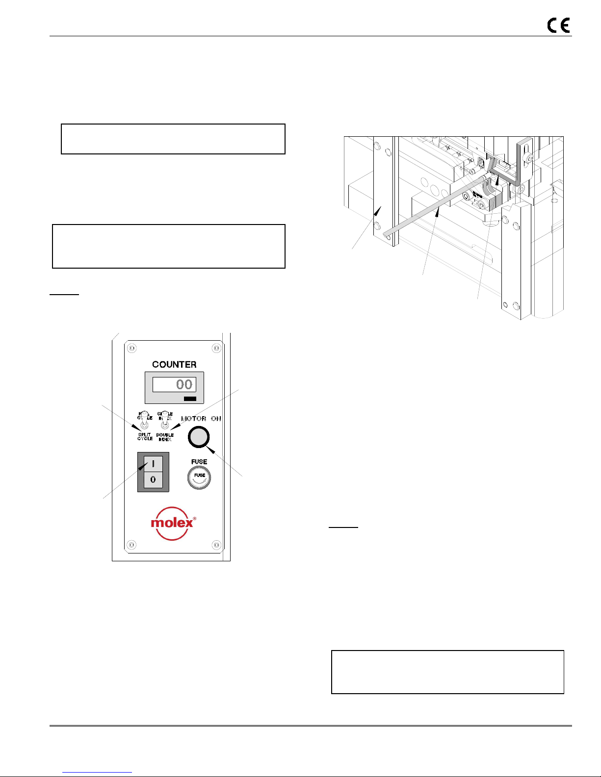
1. Push the toggle switch on the control panel to “Full
Cycle”. See Figure 3-5.
TOGGLE
SWITCH
TO FULL
CYCLE
POWER
ON
Figure 3-5
2. Turn the “Power “ switch on, the power indicator light
will light up.
3. Press the “Motor On” push button, the motor
indicator light will light up. After a 5 second delay
the press will be ready to cycle.
4. Place the prestripped wire through the slot in the
press guard and push until it contacts the wire stop.
See Figure 3-6.
FEED
SELECTOR
PUSH
MOTOR ON
5. Press the foot pedal down once. Use a sweeping
motion to the right with the crimped wire and
remove.
6. Check the crimped wire and confirm that it meets the
applicator specifications and visual inspection.
7. Repeat steps 4 and 5 for the next crimp.
GUARD
PRE-STRIPPED
Figure 3-6
WIRE
WIRE
STOP
3.4.2 Split Cycle Operation
Desription:
The split cycle is used mostly for closed barrel
terminals. This makes it easier to locate the terminal
before crimping the wire. The punch/ram will close
partially to assist in locating the terminal for the
termination. Then the wire can be placed into the
terminal and be terminated. To setup the machine
for split cycle push the toggle switch on the control
panel to “Split Cycle”. See Figure 3-5.
Steps:
1. Depress the foot switch once, the ram will lower
partially, positioning the terminal for termination.
2. Place the prestripped wire into the terminal.
3. Depress the foot switch a second time. The ram will
complete its downward stroke and return to the top
position to complete the cycle of terminating the
crimp.
CAUTION: Make sure the press guard is in position
and all setup procedures are followed. Follow the
safety and work area instructions.
Order No: TM-638017299 Release Date: 06-06-05 UNCONTROLLED COPY Page 14 of 47
Revision: D Revision Date: 12-0-02-09
Page 15
TM-3000 and TM-4000 Universal Press
Split Cycle Ram Adjustment
When setting up an applicator for split cycle operation it
may be necessary to adjust the ram for a partially closed
position (1st position), so the terminal will be captivated
in the punch and not terminated. For adjustment, the
prox sensor located on the left side of the ram cover,
needs to be adjusted. See the following steps:
Steps:
1. Depress the foot switch once, with the terminals in
the applicator. See where the punch is located in
the 1st position of the cycle.
2. If the punch is too high and does not center the
terminal so that the prestripped wire can be inserted
in the closed barrel or the punch is too low partially
crimping the terminal, the prox sensor needs to be
adjusted.
3. Open the press guard.
4. Loosen the two M12 jam nuts on the split cycle prox,
located on both sides of the prox bracket. Then
loosen the M4 jam nut holding the M4 X 25 SHCS.
Turn the screw clockwise to raise the prox or
counter-clockwise to lower the prox. See Figure 3-7.
Raise the prox if the punch is partially crimping the
terminal; or lower the prox if the ram is not closing
far enough and not centering the terminal punch.
M12 JAM NUT
PROX BRACKET
M4 JAM NUT
PROX SENSOR
1.52mm
(.06”)
MAX. GAP
TOGGLE SWITCH
TO SPLIT CYCLE
Figure 3-7
5. Retighten the M4 SHCS and the (2)M12 jam nuts
positioning the prox for the 1st position of the split
cycle. See Figure 3-7.
6. Close the press guard.
7. Repeat step 1 to check for the correct position of the
ram. (Be sure Ram is at Top-Dead-Center first.)
Note: The gap between the prox and the ram
should be 1.52mm (.06”) Max. See Figure 3-7.
CAUTION: Always return the ram to the top dead
center position or start position of the cycle before
recycling the press. This is done by manually
cycling the press. See section 3.3.
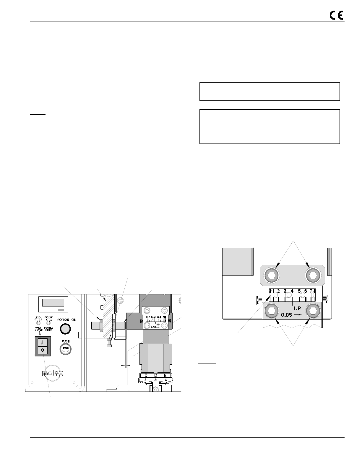
3.4.3 Crimp Adjustment
See Section 2.6.1 for Industry standard shut height.
Crimp Adjustment Full and Split Cycle
If crimp adjustment is required and cannot be made by
the cam adjustment on the applicator, the fine
adjustment dial on the press ram can be adjusted by
following the steps below.
LOOSEN M6 SHCS
ADJUSTABLE DIAL
Figure 3-8
LOOSEN M6 SHCS
Steps:
1. Open the press guard.
2. Loosen the four M6 SHCSs on the front of the press.
3. Rotate the adjustment dial to the right to raise crimp
height or to the left to decrease. Dial indicator lines
represent increments of .05mm (.002”). See Figure
3-8.
Order No: TM-638017299 Release Date: 06-06-05 UNCONTROLLED COPY Page 15 of 47
Revision: D Revision Date: 12-0-02-09
Page 16

TM-3000 and TM-4000 Universal Press
4. When adjustment is complete, retighten the four M6
SHCSs.
5. Close the guard.
6. Place a prestripped wire into the terminal and
terminate under power. Examine the quality of the
crimp.
7. Repeat steps 1 thru 6 if the desired crimp is not
achieved.
Use caution adjusting the ram downward. Over
adjustment in this direction may cause tooling
damage or breakage.
Always return the adjustment to the factory setting
before installing another applicator, or recalibrating
shut height. See Section 2.6.1.
Order No: TM-638017299 Release Date: 06-06-05 UNCONTROLLED COPY Page 16 of 47
Revision: D Revision Date: 12-0-02-09
Page 17

Molex Taped Terminal Crimp Module
4.1 Maintenance
4.2 Oiler
4.3 Troubleshooting
Section 4
Order No: ATS-638017299 Release Date: 06-06-05 UNCONTROLLED COPY Page 17 of 47
Revision: B Revision Date: 10-06-08
Page 18

TM-3000 and TM-4000 Universal Press
4.1 Maintenance
Power down the press by pressing the power button to off “O” located on the control panel.
For efficient operation the press should be cleaned daily with a soft
bristle brush to remove any carrier strip debris and terminal plating dust
from the tooling area.
Maintenance Schedule
The following is offered as a general guideline for maintenance. Tool
life can be increased with good maintenance practices or decrease with
lack of maintenance.
Item
Air Filter 100,000 Weekly
Air
Lubricator
Ram 25,000 Daily
Main Bearing 25,000 Daily
Cleaning 25,000 Daily
Frequency
Cycles
100,000 Weekly
Frequency
Time
Materials
Clean bowl and sintered
filter with denatured alcohol
SAE 10W oil. Check and
refill if used
SAE 10W oil
Oil Cup (Top of ram)
Grease fitting right side of
Press bearing lube
Use soft bristle brush on
Applicator mounting plate
4.2. Oiler
LID
Description
The wick action oiler is included with the press. The oiler
applies a thin coat of lubricant to the terminals, which
TUBE
helps with feeding and better release from termination
punches. The oiler is primarily used for terminals with
gold plating. To avoid contamination when shipped and
WICK
(PKG OF 25
#638900727)
during setup, the oiler is shipped from the factory with no
lubricant oil. The oiler should only be used on
applicators that require lubrication for smooth troublefree operation.
Oiler Position
Adjust the position of the oiler unit using the mounting screw that attaches the oiler to the quick change mounting
plate. Simply loosen the screw, slide the unit to the desired position, and tighten the screw. The unit can be removed
and placed on the rear side of the quick change mounting plate for rear-feed applications.
OIL CUP
Figure 4-8
Figure 4-9 OILER ASSEMBLY
GREASE FITTING
(OIL RESERVOIR)
MOUNTING
BRACKET
JAR
Order No: TM-638017299 Release Date: 06-06-05 UNCONTROLLED COPY Page 18 of 47
Revision: D Revision Date: 12-0-02-09
Page 19

TM-3000 and TM-4000 Universal Press
Oiler Wick
Adjust the height of the oiler wick by pulling up or pushing down on the wick to the appropriate height. The wick can
be moved using pliers or simply grab it with your fingers.
Filling the Reservoir
While firmly holding the lid, screw the jar (oil reservoir) counter clockwise until it is removed. Fill the jar with the
desired lubricant oil and replace the lid.
Replacing the Wick
While firmly holding the lid, screw the jar oil reservoir) counter clockwise until it is removed. Feed a new wick up into
the tube until it protrudes from the top end of the tube and replace the lid.
Package of 25 Wicks:
Molex Order No: 63890-0727
Lubricant Oil
Recommended oil: Transdraw B-19
Vendor: Sure Lubricants Inc.
356 South Lively Boulevard
Elk Grove Village, IL 60007-2010
Phone: 888-787-3582
Fax: 847-956-6655
E-mail: surelub@aol.com
4.3 Troubleshooting
Symptom Cause Solution
Power/Power cord failure Check supply
Loose connection Refer to control schematic
Guard interlock switch disengaged Re-Install guard
Fuse blown Replace
Motor will not run
Press will not cycle
Press partially cycles Toggle switch set to split cycle Reset the toggle switch to full cycle
On/Off switch failure Replace
Motor failure Replace
T-wrench not removed from motor Removed T-wrench from motor
Control PCB not working Replace
Solid state relay not working Replace
Control board for motor Repair or replace
Guard interlock switch disengaged Re-Install guard
Faulty footswitch Check Connection. Repair or replace
Control PCB not working Replace
Fuse blown Replace
Order No: TM-638017299 Release Date: 06-06-05 UNCONTROLLED COPY Page 19 of 47
Revision: D Revision Date: 12-0-02-09
Page 20

TM-3000 and TM-4000 Universal Press
5.1 Parts List
5.2 Assembly Drawings
5.3 Electrical and Pnuematic Schematics
Section 5
Order No: TM-638017299 Release Date: 06-06-05 UNCONTROLLED COPY Page 20 of 47
Revision: D Revision Date: 12-0-02-09
Page 21

TM-3000 and TM-4000 Universal Press
5.1. Parts List
Item No. Order No. Ref. No. Description Quantity
1 63801-7200 FE-2TC (110VAC)
2 63801-7300 FE-2TC (220VAC)
3 63801-7201
4 63801-7202
5 63801-7203
6 63801-7204
7 63801-7205
8 63801-7206
9 63801-7207
10 63801-7208
11 63801-7209
12 63801-7210
13 63801-7211
14 63801-7212
15 63801-7213
16 63801-7214
17 63801-7215
18 63801-7216
19 63801-7217
20 63801-7218
21 63801-7219 A007-NA6911 Front Bearing 1
22 64016-2501
23 64016-2502
24 64016-2503
25 63801-7281
26 63801-7222
27 63801-7283
28 63801-7224
29 63801-7284
30 63801-7285
31 63801-7286
32 63801-7287
33 63801-7288
34 63801-7631
35 63801-7232
36 63801-7233
37 63801-7234
38 63801-7235
39 63801-7236
40 63700-3845
41 63801-7237
42 63801-7238
43 63801-7239
44 63801-7240
45 63801-7241
46 63801-7242
47 63801-7243
48 63801-7244
49 63801-7245
A021-R80 Shaft E-Ring 1
TM-3000 Main Assembly (Figure 5-1 and 5-2)
Universal Press (110VAC) See Notes Below
Universal Press (220VAC) See Notes Below
A01 Press Frame 1
A02 Ram 1
A03 Follower 1
A04 Front Cap 1
A05 Press Face Plate 1
A06 Switch-TDC 1
F05 Flag Pickup 1
A08 Access Cover 1
F17 Oil Fill Cap 1
A10 Flag-Position 1
(M) B01 Split Cycle Prox 1
(M) B03 Guard Handle 1
B02 Yoke Adapter 1
B03 Mounting Block Cover 1
B04 Mounting Block 1
(M) A01 Press Yoke 1
B01 Press Shaft 1
--- Guard Slide 2
--- Guard Front 1
--- Front Guard Insert 1
(M) Rear Guard 1
(M) A02 Quick Change Plate 1
(M) Side Guard 1
(M) Name Plate (Universal Press) 1
(M) Hinge Mounting Bracket 1
(M) Guard Hinge 2
(M) A06 Guard Sensor Bracket 1
(M) Guard Bracket 1
(M) Stand-off, Guard Side 3
--- Control Panel 1
F12 Eye Bolt 1
C04 Stand off 2
C01 Terminal Guide 1
C03 Guide 2
C02 Terminal Guide Bracket 1
(M) Rotor Magnet 1
F06 Press Lamp 1
E05 Lamp Mounting Bracket 1
(M) B02 Guard Switch Prox 1
(M) Oiler Assembly (Figure 5-3) 1
F07A
F07B
(M) A03 Alignment Block 2
(M) A04 Locking Clamp 1
(M) A05 Clamp Retainer 1
∗∗∗∗Bulb-110 VAC
∗∗∗∗∗∗∗∗Bulb-220 VAC
1
1
Order No: TM-638017299 Release Date: 06-06-05 UNCONTROLLED COPY Page 21 of 47
Revision: D Revision Date: 12-0-02-09
Page 22

TM-3000 and TM-4000 Universal Press
Item No. Order No. Ref. No. Description Quantity
50 63801-7246
51 63801-7247 A007-A6909ZZ Rear Bearing 2
52
53 63801-7249
54 63801-7250
55 63801-7251
56 63801-7252
57 63801-7253
58 63801-7254
59 63801-7256
60 63801-7257
61 63801-7258
62 63801-7259
63 63801-7260
64 63801-7261
65 63801-7262
66 63801-7263
67 63801-7269
68 63801-7270
69 63801-7271
70 69018-6237
71 62500-1774
72 63801-7272
73 63801-7273
74 63801-7274
75 63801-7275
76 63801-7276
77 63801-7277
78 63801-7278
79 63801-7279
80 63801-7600
63801-7248
63801-7648
A021-R68 E-Ring 2
A021-S45 Small E-Ring 1
Note:
1. For TM-3000 Press 220VAC use assembly no. 63801-7300.
2. For TM-4000 Press (220VAC only) use assembly no. 63801-7600.
3. All parts for both 63801-7200 and 63801-7300 Presses unless otherwise specified.
4. ∗∗∗∗ Indicates parts for 63801-7200 (110VAC) Press only.
5. ∗∗∗∗ ∗∗∗∗ Indicates parts for 63801-7300 (220VAC) Press only.
6. ∗∗∗∗ ∗∗∗∗∗∗∗∗ Indicates parts for 63801-7600 (220VAC) Press only.
TM-3000 Main Assembly (Figure 5-1 and 5-2)
(M) F01 Motor with Gear Reducer 1
(M) F01
F02
F02A
F03 Relay - Motor On 1
F04 Transformer (18V) 1
(M) E04 PCB-Machine 1
E03 Sensor Flag -Motor 1
F08 Motor Shutoff Prox 1
E02 Prox Motor Shutoff Bracket 1
A09 Rear Cover 1
D01 Reel Support 1
D02 Reel Boss 2
D03 Reel Disc 2
D04 Reel-Spring 1
(M) Filter-Regulator-Lubricator 1
(M) Air Valve-3 Way 1
(M) Foot switch with cord 1
---
--(M) Slide Valve 1
(M) Label (Lightning Bolt) 1-1/2” Triangle 1
(M) Label (Eye-Glasses) 1
(M) Label (Caution) 2
(M) Plug (1/4” Tube) 2
(M) Elbow Male (1/4” Tube) for Filter-Reg.-Lubricator
(M) Elbow Male (1/4” Tube) for 3-Way Valve 3
(M) Terminal Guide Standoff 4
--- Universal Press (220VAC) See Notes Below
∗∗∗∗∗∗∗∗∗∗∗∗ Motor with Gear Reducer
∗∗∗∗ Motor Controller 110VAC
∗∗∗∗∗∗∗∗ Motor Controller 220 VAC
∗∗∗∗ Power Cord (110VAC) 20 AMP
∗∗∗∗∗∗∗∗ Power Cord (220VAC) 10 AMP
1
1
1
1
1
1
Order No: TM-638017299 Release Date: 06-06-05 UNCONTROLLED COPY Page 22 of 47
Revision: D Revision Date: 12-0-02-09
Page 23

TM-3000 and TM-4000 Universal Press
27
5.2. Assembly
35
(3)
43
(2)
72
67
44
68
77
28
76
78
75
33
(3)
13
25
34
31
M12
JAM NUT (2)
(REF)
29
26
40
79
Figure 5-1
(4)
32
24
30
(2)
22
23
74
14
(2)
Order No: TM-638017299 Release Date: 06-06-05 UNCONTROLLED COPY Page 23 of 47
Revision: D Revision Date: 12-0-02-09
Page 24

TM-3000 and TM-4000 Universal Press
5.2 Assembly (Continued)
(2)
4
5
47
56
110V
220V
110V
220V
11
7
6
16
26
48
15
17
18
49
41
45
46
42
29
REF
54
55
64
20
12
(2)
10
58
(2)
19
8
57
65
21
Figure 5-2
66
73
63
70
71
37
110V
220V
53
59
38
(2)
52
60
61
69
36
(2)
39
3
51
9
(2)
(2)
50
62
Order No: TM-638017299 Release Date: 06-06-05 UNCONTROLLED COPY Page 24 of 47
Revision: D Revision Date: 12-0-02-09
Page 25

TM-3000 and TM-4000 Universal Press
Assembly (continued)
Item No. Description Quantity
3
6
5
3
2
1
4
Figure 5-3
Oiler Assembly
Item No. 43 (63801-7240)
1 Oiler Wick 1
2 Oiler Lamp Tube 1
3 Oiler Lamp Tube Nut 2
4 Wide Mouth Glass Jar 1
5 Oiler Glass Jar Lid 1
6 Oiler Bracket 1
Order No: TM-638017299 Release Date: 06-06-05 UNCONTROLLED COPY Page 25 of 47
Revision: D Revision Date: 12-0-02-09
Page 26

TM-3000 and TM-4000 Universal Press
5.3. Electrical Schematic
Order No: TM-638017299 Release Date: 06-06-05 UNCONTROLLED COPY Page 26 of 47
Revision: D Revision Date: 12-0-02-09
Page 27

TM-3000 and TM-4000 Universal Press
5.3. Pnuematic Schematic
Americas Headquarters
Lisle, Illinois 60532 U.S.A.
1-800-78MOLEX
amerinfo@molex.com
Far East North Headquarters
Yamato, Kanagawa, Japan
81-462-65-2324
feninfo@molex.com
Figure 5-5
Far East South Headquarters
Jurong, Singapore
65-6-268-6868
fesinfo@molex.com
Visit our Web site at http://www.molex.com
European Headquarters
Munich, Germany
49-89-413092-0
eurinfo@molex.com
Corporate Headquarters
2222 Wellington Ct.
Lisle, IL 60532 U.S.A.
630-969-4550
Fax: 630-969-1352
Order No: TM-638017299 Release Date: 06-06-05 UNCONTROLLED COPY Page 27 of 47
Revision: D Revision Date: 12-0-02-09
Page 28

TM-3000 and TM-4000 Universal Press
6.1 EC Declaration of Conformity
Section 6
Order No: TM-638017299 Release Date: 06-06-05 UNCONTROLLED COPY Page 28 of 47
Revision: D Revision Date: 12-0-02-09
Page 29

TM-3000 and TM-4000 Universal Press
6.1 EC Declaration of Conformity
Order No: TM-638017299 Release Date: 06-06-05 UNCONTROLLED COPY Page 29 of 47
Revision: D Revision Date: 12-0-02-09
Page 30

TM-3000 and TM-4000 Universal Press
For more information use the Quality Crimping Handbook
And Industrial Crimping Handbook
There is no charge for these books, they can be found on the Molex Website (www.molex.com) or contact you
local Molex sales engineer
Order No: TM-638017299 Release Date: 06-06-05 UNCONTROLLED COPY Page 30 of 47
Revision: D Revision Date: 12-0-02-09
Page 31

TM-3000 and TM-4000 Universal Press
1. Taped Terminal Crimp Module
APPENDIX A
OPTIONS
Order No: TM-638017299 Release Date: 06-06-05 UNCONTROLLED COPY Page 31 of 47
Revision: D Revision Date: 12-0-02-09
Page 32

TM-3000 and TM-4000 Universal Press
TAPED TERMINAL CRIMP MODULE
Description
Operation
Maintenance
Order No: TM-638017299 Release Date: 06-06-05 UNCONTROLLED COPY Page 32 of 47
Revision: D Revision Date: 12-0-02-09
Order Number 64016-2000
Instruction Manual
Page 33

TM-3000 and TM-4000 Universal Press
WARNING
NEVER USE THIS CRIMP MODULE IN A PRESS WITHOUT GUARDS OR SAFETY DEVICES THAT ARE
INTENDED TO PREVENT HANDS FROM REMAINING IN THE DIE SPACE.
NEVER OPERATE, SERVICE, INSTALL, OR ADJUST THIS CRIMP MODULE WITHOUT PROPER
INSTRUCTION AND WITHOUT FIRST READING AND UNDERSTANDING THE INSTRUCTIONS IN
THIS MANUAL AND ALL APPLICABLE PRESS MANUALS.
NEVER INSTALL OR SERVICE THIS CRIMP MODULE WHILE CONNECTED TO ANY ELECTRICAL
POWER SOURCE. DISCONNECT POWER BY UNPLUGGING THE PRESS FROM ITS POWER
SOURCE.
CAUTION THE MOLEX CRIMP MODULE IS DESIGNED TO OPERATE ONLY IN THE MOLEX TM-3000 OR
TM-4000 PRESSES. INSTALLATION IN OTHER CRIMP PRESSES CAN CAUSE SEVERE TOOL
DAMAGE. IT IS ADVISABLE THAT BEFORE INSTALLATION, A CHECK OF THE PRESS SHUT
HEIGHT BE PERFORMED. MOLEX WILL NOT BE LIABLE FOR ANY DAMAGES AS A RESULT
OF INSTALLATION IN A PRESS WITH AN IMPROPERLY SET SHUT HEIGHT.
CAUTION MOLEX CRIMP SPECIFICATIONS ARE VALID ONLY WHEN USED WITH MOLEX TERMINALS
AND MOLEX APPLICATION TOOLING.
WORK SAFELY AT ALL TIMES
For Service, Contact Your
Local Molex Sales Office
Molex Application Tooling Group
2200 Wellington Court
Lisle, IL 60532
Tel: (630) 969-4550
Fax: (630) 505-0049
Visit our Web site at http://www.molex.com
Order No: TM-638017299 Release Date: 06-06-05 UNCONTROLLED COPY Page 33 of 47
Revision: D Revision Date: 12-0-02-09
Page 34

TM-3000 and TM-4000 Universal Press
Table of Contents
SECTION
1 General Description
2 Setup, Adjustments, and Operation
3 Maintenance
4 Parts List, Assembly Drawings, Troubleshooting, and Guard upgrade
APPENDIX
A Pull Force Testing
Order No: TM-638017299 Release Date: 06-06-05 UNCONTROLLED COPY Page 34 of 47
Revision: D Revision Date: 12-0-02-09
Page 35

TM-3000 and TM-4000 Universal Press
1.1 Description
1.2 Features
1.3 Technical Specifications
1.4 Delivery Check
1.5 Tools
1.6 Specification Sheets
Section 1
General Description
Order No: TM-638017299 Release Date: 06-06-05 UNCONTROLLED COPY Page 35 of 47
Revision: D Revision Date: 12-0-02-09
Page 36

TM-3000 and TM-4000 Universal Press
AND P
RESS YOKE
Principal Mechanical Parts of the Taped Terminal Crimp Module
PRESS YOKE
PUNCH HOLDER
ATP-301
CARRYING
HANDLE
TAPE GUIDE
COVER
Figure 1-1
RAM
WIRE STOP/
STRIPPER UNIT
ANVIL MOUNT
STORAGE FOR
PUNCH HOLDER
FEED
CYLINDER
STORAGE
FOR
WIRE STOP/
STRIPPER
Order No: TM-638017299 Release Date: 06-06-05 UNCONTROLLED COPY Page 36 of 47
Revision: D Revision Date: 12-0-02-09
Page 37

TM-3000 and TM-4000 Universal Press
General Description
Description
The taped terminal crimp module provides an
effective method of applying a wide range of
side feed tape-mounted terminals to prestripped discrete wire(s) from 4 to 30 AWG.
The crimp module and press combination
replaces the Molex ATP-301 Press (19228-
0030) and the Molex ATP-201 Press (19047-
0001).
This crimp module operates only in the Molex
TM-3000 and TM-4000 Universal Presses. The
crimp module uses quick-change modular
tooling, requires little or no adjustments, and is
intended for mid-volume to high-volume, semiautomatic operations.
Molex offers the following crimp presses for
operating the crimp module:
TM-3000 Universal Press 120V 50-60 Hz.
63801-7200
TM-3000 Universal Press 240V 50-60 Hz.
63801-7300
The TM-3000 should be used for 10-30
AWG terminals.
TM-4000 Universal Press 240V 50-60 Hz.
63801-7600
The TM-4000 should be used for 4-30 AWG
terminals.
General Features
Independent adjustment of insulation crimp height.
Tooling is accessed from the front of the module,
simplifying change over.
No track adjustment is required.
Compatible with the Molex TM-3000 and TM-4000
Universal Presses only. It does NOT fit into
Molex TM-40, TM-42, or TM-2000 presses.
No terminal feed adjustment is required.
Uses crimp tooling from existing Molex ATP-201 and
ATP-301 crimp presses.
Technical Specification
Dimensions
Crimp Module Only
Width: 140mm (5.5")
Depth: 136mm (5.3")
Height: 175mm (6.9")
(ram down)
Weight 4.1kg (9lb)
Guarding
The crimp module is intended to be used with
the guards supplied on the TM-3000 or TM4000 Universal Press.
A special retrofit guard kit is available when the
crimp module is installed on earlier TM-3000
press models. See Section 4.3.
Caution: DO NOT operate the crimp
module without press guards in place.
Delivery Check
Carefully remove the crimp module from its
shipping container and determine that the
following items are included in the package.
Crimp Module 1
Air line Kit 1
Press Guard Kit (if required) 1
Instruction Manual 1
NOTE: Terminal crimp tooling is not included with
the crimp module and must be ordered separately.
Order No: TM-638017299 Release Date: 06-06-05 UNCONTROLLED COPY Page 37 of 47
Revision: D Revision Date: 12-0-02-09
Page 38

TM-3000 and TM-4000 Universal Press
Tools
The following tools are recommended for setup
and adjustments to the crimp module:
1. Metric standard hex wrench set
2. Inch standard hex wrench set
3. Wire stripper / cutter
4. Crimp Micrometer or caliper
Specification Sheets
Specification sheets are available for all crimp
tooling. The specification sheet contains the
following:
Applicable terminal numbers
Wire AWG ranges
Insulation diameter ranges
Pull Force specification
Strip lengths
Slug height specification
Tooling parts lists and assembly drawings
The specification sheet is available on the Molex
website (www.molex.com).
Order No: TM-638017299 Release Date: 06-06-05 UNCONTROLLED COPY Page 38 of 47
Revision: D Revision Date: 12-0-02-09
Page 39

TM-3000 and TM-4000 Universal Press
Set-Up and Operation
2.1 Shut Height
2.2 Setup
2.3 Crimp Height Adjustments
2.4 Crimp Tooling Installation and Removal
2.5 Specific Crimp Module Adjustments
2.6 Operation
Section 2
Order No: TM-638017299 Release Date: 06-06-05 UNCONTROLLED COPY Page 39 of 47
Revision: D Revision Date: 12-0-02-09
Page 40

TM-3000 and TM-4000 Universal Press
Figure 2
-2
Read the following instructions before
attempting to operate the crimp module.
2.1. Shut Height
The Molex Taped Terminal Crimp Module operates only in
the TM-3000 and TM-4000 presses with standard shut
height of 135.80mm (5.346"). Installation in crimp presses
with other than standard shut heights can cause severe
tool damage. Before installing the crimp module, the
press shut height must be verified. The correct shut
height is required for proper crimping without causing tool
damage.
The shut height of the TM-3000 and the TM-4000 presses
are preset at the factory and labeled on the front of the
press. Over time, however, the press may wear causing a
change in the shut height.
The shut height of the press can be checked with a shut
height gauge, which is calibrated under load to achieve
the 135.80mm (5.346") measurement. It is recommended
that the shut height be checked monthly. A shut height
gauge is available from most press manufacturers.
PRESS
SHUT HEIGHT GAUGE
Measuring Press Shut Height
1. Disconnect the power supply from the press. Remove
the machine guards if necessary.
PRESS QUICK CHANGE
MOUNTING PLATE
Figure 2-1
2. Remove the applicator from the press. Make sure
that the bottom of the press ram and quick change
mounting plate are free of foreign material.
3. Place the shut height gauge into the press on the
press quick change mounting plate. See Figure 2-
1.
4. Manually cycle the press to the full down stroke
position. (See the TM-3000 press instructions on
manually cycling the press.)
5. Read the shut height measurement from the front
of the gauge. Follow gauge manufacturer’s
instructions; usually the gauge reads “0” at the
correct shut height.
6. If shut height adjustment is necessary:
LOOSEN M6 SHCS
ADJUSTABLE DIAL
LOOSEN M6 SHCS
a. Loosen the four M6 SHCS on the front of the
press.
b. Rotate the adjustment dial to the right to raise
shut height or to the left to decrease. Dial
indicator lines represent increments of .05mm
(.002”). See Figure 2-2.
c. When adjustment is complete, retighten the four
M6 SHCS.
7. Repeat the above steps until the correct shut height
is obtained.
8. Shut height gauges must be calibrated on a regular
basis.
2.2. Set-Up
The principal mechanical parts of the crimp module are
illustrated in the assembly drawings (Section 4-1).
Order No: TM-638017299 Release Date: 06-06-05 UNCONTROLLED COPY Page 40 of 47
Revision: D Revision Date: 12-0-02-09
Page 41

TM-3000 and TM-4000 Universal Press
Crimp Module Installation and Removal
1. Turn off the press and disconnect the power. Open
the press guard.
2. Clean the quick-change mounting plate of scrap or
chips that may interfere with the crimp module
installation.
3. Using a 3mm hex wrench, loosen the set screw
holding the press yoke. Pull the press yoke straight
down and remove it from the press. (Note: a storage
hole is provided on right side of the crimp module
frame to keep the press yoke)
4. Install the press yoke furnished with the crimp module
in the press ram. Tighten the set screw securely.
5. Using a 4mm hex wrench, turn the M5 SHCS
clockwise until the locking clamp is fully opened.
6. Visually align the crimp module’s base plate slots with
the location clamps on the press quick-change
mounting plate.
PRESS YOKE
LOCATOR
CLAMPS
RAM
ADAPTER
QUICK
CHANGE
PLATE
LOCKING
CLAMP
Figure 2-2
M5
SHCS
BASE PLATE
7. Slide the crimp module onto the quick-change
mounting plate until the two notches on the left side
engage against the stops, and at the same time,
guide the ram adapter into the press yoke. See
Figure 2-2.
8. To lock the crimp module, turn the M5 SHCS
counterclockwise until tight.
9. Connect the air lines from the feed cylinder to the
press air valve. The cylinder port closest to the
module frame must be connected to the “normally
open” valve port. The other cylinder port (with the
flow control valve) must be connected to the
“normally closed” valve port.
10. Close the press guard.
11. Remove the crimp module by reversing the previous
steps. When storing the crimp module, always
leave a strip of terminals in the module on the anvils
to prevent damage to the tooling. See Section 3.5
Storage.
Punch and Anvil Alignments
Note: Always clean mounting surfaces of crimp tooling
and tooling holders prior to alignment.
1. Disconnect power from the press and open the
machine guard.
2. Using a 5/32” hex wrench, slightly loosen the anvil
mounting screw. See Figure 2-3.
3. Slowly hand-cycle the ram of the press to bottom of
its stroke. With the punches engaging the anvils,
securely tighten the anvil mounting screw to ensure
alignment of punches and anvils.
4. Hand cycle the press ram to its up position.
5. Close the machine guard and restore power to the
press.
ANVIL
LOOSEN THE
#10 SHCS
Figure 2-3
2.3. Crimp Height Adjustments
Conductor Crimp Height Adjustment
1. Obtain a piece of solder, approximately 40mm (1.5”)
long and approximately 0.5mm (.02”) larger in
diameter than the crimped slug height. If the solder
Order No: TM-638017299 Release Date: 06-06-05 UNCONTROLLED COPY Page 41 of 47
Revision: D Revision Date: 12-0-02-09
Page 42

TM-3000 and TM-4000 Universal Press
diameter is too large the crimped slug will have large
extrusions, making it difficult to measure the overall
slug height.
2. With no terminals in the applicator, lay the solder
across the anvils and cycle the press (by hand or
under power).
3. Using a crimp micrometer or dial caliper, measure the
solder slug height and compare to specification.
4. If adjustments are necessary, turn off the press and
open the machine guard.
5. The conductor crimp height is based on the conductor
punch contacting the conductor anvil. If the press shut
height was correctly set prior to crimp module
installation (see section 2.1) there should be no need
to adjust conductor crimp height. However, some of
the larger terminal crimps may cause minor press
frame deflection which can be compensated by
adjusting the press shut height. See section 2.1 for
shut height adjustment.
NOTE: Crimp height adjustments for closed-barrel
industrial terminals are always based on solder slug
heights, not terminal crimp heights.
1. Load the terminals, close the machine guard, and
crimp several wires under power.
2. Perform a pull test on the conductor crimp to verify
the mechanical integrity of the crimp. See Appendix
A-Pull Force Test.
Insulation Crimp Height
1. Place a stripped length of the appropriate wire into the
terminal and crimp under power.
2. Observe quality of insulation crimp.
3. If adjustments are necessary, turn off the press.
Open the machine guard.
4. Using a 5/32” hex wrench, loosen the #10 SHCS
holding the punches.
5. Rotate the insulation adjusting cam to achieve the
desired insulation height. There are three cam
positions (marked L, M, and S) for large, medium, and
small diameter wires. The cam must be in one of the
three positions; do not adjust it between positions.
See Figure 2-4.
6. While holding the punches up against the punch
holder, securely tighten the #10 SHCS.
7. Close the machine guards, restore power, and crimp
a wire under power. Inspect the insulation crimp and
make further adjustments if needed.
INSULATION CAM
LOOSEN THE
#10 SHCS
PUNCHES
Figure 2-4
Note: Due to the large variety of insulation wall
thickness, materials, and durometers, Molex does not
specify insulation crimp height.
2.4. Crimp Tooling Removal and Installation
Caution: Always disconnect power before installing or
removing tooling.
Removal and Installation of ATP-301 Style Punches
NOTE: Always clean mounting surfaces of crimp tooling
and tooling holders prior to installation.
PUNCH HOLDER
O-RING
PUNCHES
#10 SHCS
Figure 2-5
Order No: TM-638017299 Release Date: 06-06-05 UNCONTROLLED COPY Page 42 of 47
Revision: D Revision Date: 12-0-02-09
Page 43

TM-3000 and TM-4000 Universal Press
1. Disconnect power from the press. Open the machine
guard.
2. If the ram is down, move it manually to the full up
position.
3. To remove the punches, use a 5/32” hex wrench to
remove the #10 SHCS holding the punches to the
punch holder. See Figure 2-5.
4. Remove the screw, punches, and O-ring together.
Some tool kits may include a spacer plate (behind the
conductor punch).
5. To install, place the punches with the spacer (if used)
and O-ring against the punch holder and securely
tighten the #10 SHCS. The conductor punch (“E2”)
goes against the punch holder and the insulation
punch (“I2”) is stacked on the conductor punch. Make
sure the etched “E2” or “I2” on each punch faces
outward.
Note: The press should be hand-cycled after
installing punches to insure a free fit between punch
and anvil. If excessive resistance is felt, check for an
incorrectly installed punch and/or anvil misalignment.
Removal and Installation of ATP-301 Style Anvils
ANVIL MOUNT
O-RING
ANVILS
NOTE THE SIDE
PLATE POSITION
Figure 2-6
#10 SHCS
NOTE: Always clean mounting surfaces of crimp tooling
and tooling holders prior to installation.
1. Disconnect power from the press. Open the machine
guard.
2. If the ram is down, move it manually to the full up
position.
3. To remove the anvils, use a 5/32” hex wrench to
remove the #10 SHCS holding the anvils to the anvil
mount. See Figure 2-6.
4. Remove the screw, anvils, and O-ring together.
Some tool kits may include a spacer plate (behind
the conductor anvil).
5. To install, place the anvils with the spacer (if used)
and O-ring against the anvil mount, leaving the
mounting screw slightly loose. The conductor anvil
(“E1”) is installed first and the insulation anvil (“I1”)
is stacked onto it. Make sure the etched “E1” or
“I1”on each anvil face outward.
WARNING: Use the mounting screws that are
furnished with the ATP tool kit. The feed
mechanism may become damage when using
screws that are too long.
6. The side plates must be a close fit to the width of
the anvils. For the ATP-301 style anvils, the step on
the side plates must be toward the outside. If it is
not, loosen the M4 SHCS and reverse the side
plate.
7. The anvils must be aligned to the punches before
tightening the screws. See section 2.2 (Set Up;
Punch and Anvil Alignments).
Removal and Installation of ATP-201 Style Punches
RAM
SET SCREW
VISIBLE IN
THE HOLE
RAM IN THE
FULL UP
POSITION
ATP-201
PUNCH
Figure 2-7
Order No: TM-638017299 Release Date: 06-06-05 UNCONTROLLED COPY Page 43 of 47
Revision: D Revision Date: 12-0-02-09
Page 44

TM-3000 and TM-4000 Universal Press
1. Disconnect power from the press. Open the
machine guard.
2. If the ram is down, move it manually to the full up
position.
3. To remove the punch assembly, use a 3mm hex
wrench to loosen the set screw on the front of the
ram. This screw is accessible through the
module’s front cover. See Figure 2-7.
4. With the set screw loosened, pull the punch
assembly straight down.
5. To install the punch assembly, orient the
assembly so the flat on the round stub faces
forward. Put the stub into the hole in the bottom
of the ram and push the punch assembly up
against the bottom of the ram. See Figure 2-8.
RAM
FLAT FACE
OF THE ATP-201
PUNCH FACING
FORWARD
Figure 2-8
6. With the punch assembly in the ram, tighten the
set screw securely.
Note: The press should be hand-cycled after
installing the punch assembly to insure a free fit
between punch and anvil. If excessive resistance is
felt, check for an incorrectly installed punch and/or
anvil misalignment.
Removal and Installation of ATP-201 Style Anvils
NOTE: Always clean mounting surfaces of crimp tooling
and tooling holders prior to installation.
1. Disconnect power from the press. Open the
machine guard.
2. If the ram is down, move it manually to the full up
position.
3. To remove the anvils, use a 5/32” hex wrench to
remove the #10 SHCS holding the anvils to the anvil
mount. See Figure 2-9.
ANVIL MOUNT
O-RING
ANVIL
NOTE THE SIDE
PLATE POSITION
Figure 2-9
#10 SHCS
4. Remove the screw, anvil(s), and O-ring together.
5. To install, place the anvil(s) and O-ring against the
anvil mount, leaving the mounting screw slightly
loose. The conductor anvil (“E1”) is installed first
and the insulation anvil (“I1”) is stacked onto it.
Make sure the etched “E1” or “I1”on each anvil face
outward.
WARNING: Use the mounting screws that are
furnished with the ATP tool kit. Screws that are to
long may damage the feed mechanism.
6. The side plates must be a close fit to the width of
the anvils. For the ATP-201 style anvils, the step on
the side plates must be toward the inside. If it is
not, loosen the M4 SHCS and reverse the side
plate.
7. The anvils must be aligned to the punches before
tightening the screws. See section 2.2 (Set Up;
Punch and Anvil Alignments).
2.5. Crimp Module Adjustments
Terminal Feed Adjustments
The tape feed mechanism is a ratcheting wheel and has
no adjustable features.
Order No: TM-638017299 Release Date: 06-06-05 UNCONTROLLED COPY Page 44 of 47
Revision: D Revision Date: 12-0-02-09
Page 45

TM-3000 and TM-4000 Universal Press
Feed Speed Adjustments
Terminal feed speed is controlled by the flow control
valve on the feed cylinder. Loosen the locking ring, then
turn the adjustment knob clockwise (CW) to reduce the
feed speed or counterclockwise (CCW) to increase the
feed speed. See Figure 2-10.
Adjustments to the feed speed should be made
gradually.
When adjustment is complete, turn the locking ring until it
is finger-tight.
KNOB
LOCKING
RING
Figure 2-10
FEED
CYLINDER
Terminal Stripper Adjustment
ADJUST
M5 SHCS
M5 SHCS
Figure 2-11
ADJUST
Some terminals have a tendency to stick in the
conductor punch after being crimped. The terminal
stripper is used to shed the terminal away from the
retracting punches.
1. Disconnect power from the press. Open the
machine guard.
2. If the ram is down, move it manually to the full up
position.
3. To adjust the stripper in and out, use a 4mm hex
wrench to loosen the M5 SHCS on the side of the
stripper. Move the stripper toward the punches, but
not too close or it could interfere with the ram
stroke. See Figure 2-11. Tighten the M5 SHCS
when adjustment is complete.
4. To adjust the stripper up and down, use a 4mm hex
wrench to loosen the M5 SHCS on the front of the
stripper. Move the stripper down until it is just
above the taped terminal on the anvils. See Figure
2-11. Tighten the M5 SHCS when adjustment is
complete.
NOTE: If the stripper is adjusted down too far it may
interfere with the terminal feed motion.
Wire Stop Adjustment
The wire stop is used when the terminal being crimped
does not have an internal wire stop tab. Some larger
ring terminals fall into this category.
M5 SHCS
ADJUST
WIRE STOP
TERMINAL
Figure 2-12
Order No: TM-638017299 Release Date: 06-06-05 UNCONTROLLED COPY Page 45 of 47
Revision: D Revision Date: 12-0-02-09
Page 46

TM-3000 and TM-4000 Universal Press
ON ANVIL
1. Disconnect power from the press. Open the machine
guard.
2. If the ram is down, move it manually to the full up
position.
3. To adjust the wire stop, loosen the M5 SHCS on the
side of the stripper. Move the wire stop in or out until it
is near the end of the terminal barrel. See Figure 2-12.
Tighten the M5 SHCS when adjustment is complete.
NOTE: Since they are mounted to the same block,
adjustments to the wire stop will also influence the
terminal stripper. To achieve full adjustment of the wire
stop, the stripping tool may need to be removed from the
block.
2.6 Operation
Loading and Unloading Tape
1. Applicable terminals are listed on the Crimp Tooling
Specification Sheet. Do not crimp terminals that are
not listed on the Specification Sheet.
2. Disconnect power from the press. Open the machine
guard.
3. The tape will be easier to “start” in the track if the
corner of the tape is trimmed as shown in Figure 2-13.
4. Open the tape track cover by pulling out the spring-
loaded knob and lifting the cover up. A hole is
provided in the module frame for the knob’s pin to
enter to hold the track cover open. See Figure 2-14.
5. Load the taped terminal strip from the front of the
module, engaging the slots in the tape with the teeth
on the feed wheel. Make sure the terminal is also
centered above the crimp anvils. See Figure 2-15.
TRIM THE CORNER
OF THE TAPE
Figure 2-13
HOLE
TRACK COVER
LIFT KNOB UP
TRACK
COVER CLOSED
PULL KNOB OUT
Figure 2-14
6. Pull out the spring-loaded knob and lower the track
cover, allowing the pin to engage the lower hole.
7. Unloading the tape is the reverse process.
TAPE SLOT
TERMINAL
Figure 2-15
Tape De-Reeling Information
The tape reel should be mounted on the reel arm of
the press, with the printed side of the reel facing the
operator. The tape de-reels counterclockwise
(CCW).
To prevent tape feed jams, the tape should enter the
press guard below the bottom horizontal bar. If the
tape is threaded between the bars, a terminal may
become snagged on the bar during feeding. See
Figure 2-16.
TERMINAL
Order No: TM-638017299 Release Date: 06-06-05 UNCONTROLLED COPY Page 46 of 47
Revision: D Revision Date: 12-0-02-09
Page 47

TM-3000 and TM-4000 Universal Press
While operating the crimp module, the tape entering the press should not become taut. The operator should
occasionally turn the terminal reel to maintain a slack loop.
The scrap tape exits below the press guard.
Removal of Crimped Terminals from Tape
After being crimped, the tape feed will advance the terminal one position to the right. It is the operator’s
responsibility to remove the crimped terminal from the tape.
If crimped wires are allowed to accumulate on the tape they will eventually cause a tape feed jam.
To prevent tape damage, the terminal should be pulled off the tape towards the operator’s right. This sideways
action makes it easier for the terminal to break free from the adhesive holding it to the tape.
TAPE REEL
TAPE ENTERS
BELOW GUARD
TAPE EXIT
Figure 2-16
Order No: TM-638017299 Release Date: 06-06-05 UNCONTROLLED COPY Page 47 of 47
Revision: D Revision Date: 12-0-02-09
 Loading...