

molex TCDEC-8B4P-DYU-G8, TCDEC-8B4P-D1U-G8, TCDEC-8B4B-D1U-G8, TCDEC-8B4B-D1U-GW, TCDEC-8B4P-D1U-GW Original Instructions Manual
...Page 1
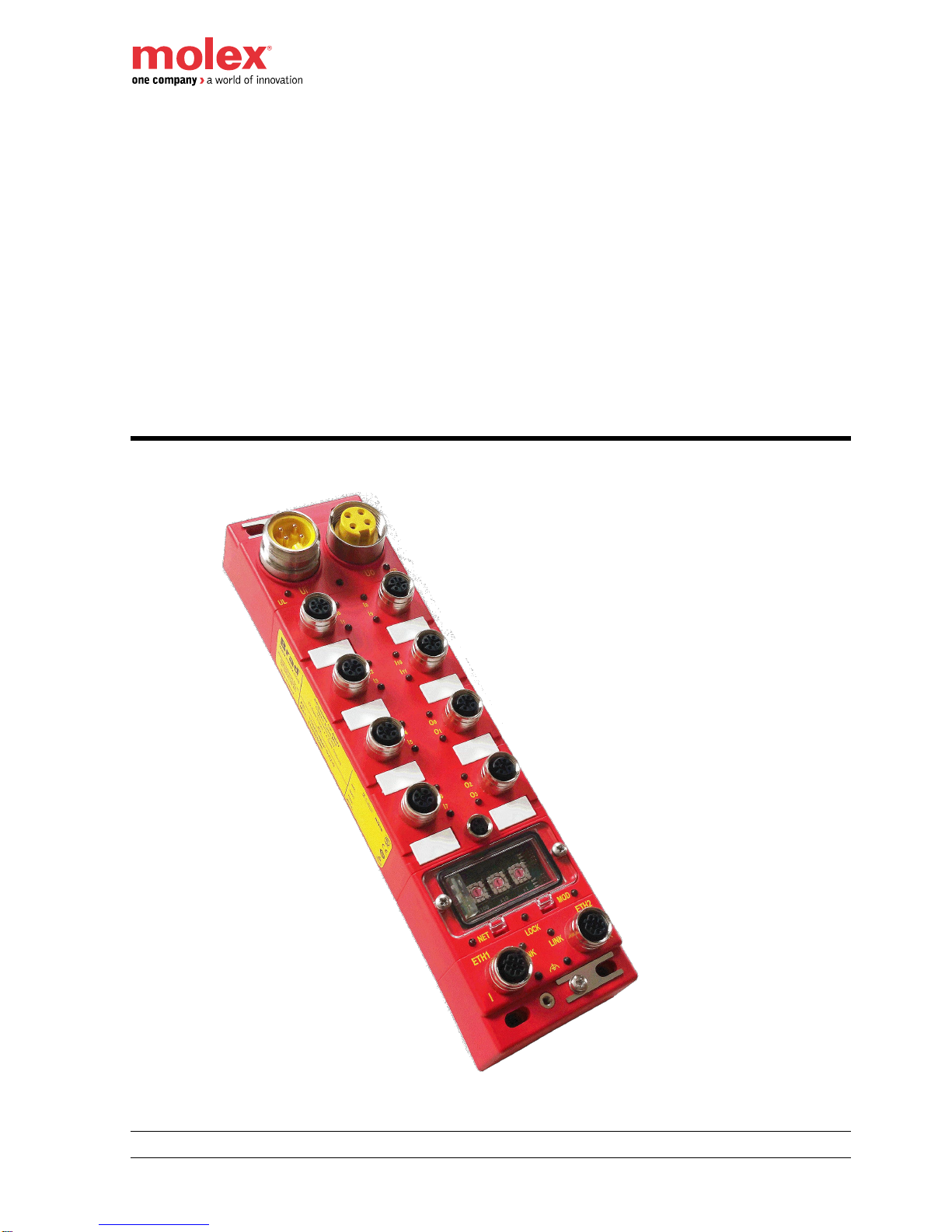
EtherNet/IP™ CIP Safety™ IP67 HarshIO 600
1 IP67 Safety Digital I/O Modules
User’s Safety Manual
‘ORIGINAL INSTRUCTIONS’
EtherNet/IP™ CIP Safety™ HarshIO
IP67 Digital I/O Modules
Brad™ from Molex
Version 1.2
June 06th, 2017
Page 2

EtherNet/IP™ CIP Safety™ IP67 HarshIO 600
2 IP67 Safety Digital I/O Modules
Revision History
Date
Author
Changes
Revision
February 04, 2016
E. Gory
Release version
1.0
May 19, 2016
E. Gory
Page 34 – Output sourcing - Update wiring schematic with
24 VDC on Pin1
Page 42 – Add 5-pole product references
Page 84 – Add product code in decimal
New “Safety I/O connections” chapter
Update template of “Declaration of Conformity” (DoC)
1.1
June 06, 2017
E. Gory
Page 27 – Update concerning the safety classes
Page 42 – Add important note when UB is in overvoltage
Page 61 – Correction of 5-pole power connector wiring
Page 80 – Correction of the default Gateway address
when using the static IP method
Page 136 – Update of the Safety Reset procedure
1.2
Although every effort has been made to ensure the accuracy of this document, all information is subject to
change without notice. Molex takes no liability for any errors in this document or for direct, indirect, or
consequential damage resulting from the use of this manual.
Page 3

EtherNet/IP™ CIP Safety™ IP67 HarshIO 600
3 IP67 Safety Digital I/O Modules
STATEMENT OF LIMITED WARRANTY
Brad™ from Molex, manufacturer of HarshIO products, warrants to the Buyer that products, except software,
manufactured by Brad™ will be free from defects in material and workmanship. Brad™ obligation under this
warranty will be limited to replacing the defective parts within one year of the date of installation. Products may
be returned by Buyer only after permission has been obtained from Molex. Buyer will prepay all freight charges
to return any products to the facility designated by Brad™.
Brad™ further warrants that any software supplied as part of a product sale, except obsolete products, will be
free from non-conformances with Brad™ published specifications for a period of 90 days from the time of
delivery. While Brad™ endeavors to improve the features and performance of software associated with its
products, no effort on the part of Brad™ to investigate, improve or modify HarshIO modules firmware at the
request of a customer will obligate Brad™ in any way.
For the convenience of existing customers, Brad™ continues to supply certain products that are classified as
obsolete. No warranty on the software features of these products is stated or implied and Brad™ specifically is
not obligated to improve the design of these products in any way. Information about the status of any product
is available upon request and customers are advised to inquire about the status of older products prior to
making a purchase.
This limited warranty does not cover losses or damages which occur in shipment to or from the Buyer or due to
improper installation, maintenance, misuse, neglect or any cause other than ordinary commercial or industrial
applications. All such warranties are hereby expressly disclaimed. No oral or written information or advice
given by Brad™ or Brad’s representative shall create a warranty or in any way increase the scope of this
warranty. This limited warranty is in lieu of all other warranties whether oral or written, expressed or implied.
Brad’s liability shall not exceed the price of the individual units, which are the basis of the claim. In no event
shall Brad™ be liable for any loss of profits, loss of use of facilities or equipment, or other indirect, incidental or
consequential damages.
Although every effort has been made to ensure the accuracy of this document, all information is subject to
change without any notice. Brad™ takes no liability for any errors in this document or for direct, indirect, or
consequential damage resulting from the use of this manual.
The examples and diagrams in this manual are included solely for illustrative purposes. Because of the many
variables and requirements associated with any particular installation, Brad™ cannot assume responsibility or
liability for actual use based on the examples and diagrams.
COPYRIGHTS and TRADEMARKS
Reproduction of the contents of this manual, in whole or in part, without written permission of Molex is
prohibited.
Mini-Change®, Ultra-Lock™, Brad™ are all registered trademarks of Molex, Inc.
All other products or trademarks are the property of their respective owners.
Page 4

EtherNet/IP™ CIP Safety™ IP67 HarshIO 600
4 IP67 Safety Digital I/O Modules
This page intentionally left blank.
Page 5

EtherNet/IP™ CIP Safety™ IP67 HarshIO 600
5 IP67 Safety Digital I/O Modules
Table of contents
1. About This Manual ............................................................................... 8
About this manual .................................................................................................... 8
2. General Safety Instructions .............................................................. 11
Intended use .......................................................................................................... 11
Responsibility of the user ...................................................................................... 11
Documentation ...................................................................................................... 12
Maintenance .......................................................................................................... 12
Spare parts ............................................................................................................ 12
Shipping ................................................................................................................ 12
Disposal ................................................................................................................. 13
Education of the personnel ................................................................................... 13
Personal protective equipment .............................................................................. 13
Special hazards ..................................................................................................... 14
Sign-posting .......................................................................................................... 15
3. Product Overview .............................................................................. 16
Introduction ............................................................................................................ 16
Functional safety - safety relevant parameters ..................................................... 18
Product environmental and safety instructions ..................................................... 19
Product features .................................................................................................... 21
Ultra-Lock M12 connectivity .................................................................................. 21
Ordering information.............................................................................................. 22
Ethernet topologies ............................................................................................... 23
4. Functional Safety Functions ............................................................. 27
Safety States ......................................................................................................... 27
Safety Inputs ......................................................................................................... 28
Safety Sourcing Outputs (TCDEC-8B4P-D1U-Gx and TCDEC-8B4P-DYU-Gx) .. 33
Bipolar Safety Outputs (TCDEC-8B4B-D1U-Gx and TCDEC-8B4B-DYU-Gx) ..... 37
I/O Status .............................................................................................................. 39
Behavior in case of fault ........................................................................................ 39
Response Time ..................................................................................................... 41
5. Product Characteristics .................................................................... 42
Hardware characteristics ....................................................................................... 42
Mechanical characteristics .................................................................................... 47
Physical I/O mapping ............................................................................................ 48
Safety I/O assemblies ........................................................................................... 49
Safety I/O connections .......................................................................................... 50
Safety I/O data mapping ....................................................................................... 52
Pin assignment ...................................................................................................... 60
LED assignment .................................................................................................... 62
6. Product installation and wiring ........................................................ 66
Page 6

EtherNet/IP™ CIP Safety™ IP67 HarshIO 600
6 IP67 Safety Digital I/O Modules
Power supply ......................................................................................................... 66
Ethernet connection .............................................................................................. 67
Module grounding .................................................................................................. 70
I/O wiring ............................................................................................................... 71
7. Product Deployment .......................................................................... 78
Getting Started ...................................................................................................... 78
IP address setting .................................................................................................. 78
EDS files ................................................................................................................ 85
Import HarshIO Safety EDS into Rockwell hardware description library .............. 89
Configure HarshIO Safety module into Rockwell RSLogix 5000 project .............. 97
Safety I/O assemblies ......................................................................................... 100
Configure HarshIO Safety module in Molex SNCT ............................................. 103
Connection and testing of HarshIO Safety module in RSLogix 5000 ................. 119
8. EtherNet/IP Behavior ....................................................................... 122
I/O behavior ......................................................................................................... 122
IDLE behavior ...................................................................................................... 122
Duplicate IP address ........................................................................................... 122
EtherNet/IP Object Classes ................................................................................ 123
9. Product Replacement ...................................................................... 131
Before to start ...................................................................................................... 131
Replacement procedure ...................................................................................... 132
Verification ........................................................................................................... 133
10. SNCT Configuration Software ........................................................ 134
Overview ............................................................................................................. 134
Safety Reset ........................................................................................................ 136
Lock / Unlock Configuration ................................................................................ 142
Stored IP Address using DHCP Server............................................................... 149
IP Address Conflict .............................................................................................. 155
Ethernet Port Diagnostics ................................................................................... 156
Module Information .............................................................................................. 157
Set/Reset password ............................................................................................ 159
Additional Information.......................................................................................... 162
Download Firmware ............................................................................................ 164
Print module configuration .................................................................................. 169
Log (Emergency Mode) ....................................................................................... 172
11. Product Package .............................................................................. 173
Product package ................................................................................................. 173
USB Stick ............................................................................................................ 173
Memory Key ........................................................................................................ 174
12. Web Server Interface ....................................................................... 176
How to connect the web server ........................................................................... 176
General information ............................................................................................. 177
Page 7

EtherNet/IP™ CIP Safety™ IP67 HarshIO 600
7 IP67 Safety Digital I/O Modules
Diagnostic information ......................................................................................... 178
13. Selection of Cables and Cordsets .................................................. 180
Overview ............................................................................................................. 180
14. Certifications .................................................................................... 181
TUV Certificate .................................................................................................... 182
EU Declarations of Conformity ............................................................................ 183
15. Product Support .............................................................................. 185
Warranty conditions ............................................................................................. 185
Product Information ............................................................................................. 185
Technical Support ............................................................................................... 186
Page 8

EtherNet/IP™ CIP Safety™ IP67 HarshIO 600
8 IP67 Safety Digital I/O Modules
1. About This Manual
This Safety Manual describes the IP67 digital safety I/O modules (also called HarshIO) from Molex.
About this manual
Chapter 1: About This Manual
This is this present chapter.
Chapter 2: General Safety Instructions
This chapter gives an overview of all important safety aspects for optimum protection of the personnel, as well
as for the safe and fault-free operation.
Chapter 3: Product Overview
This chapter gives an overview of the product usage and main features.
Chapter 4: Safety Functions
This chapter gives a presentation of the characteristics of the Safety Inputs and Safety Outputs of the module.
Chapter 5: Product Characteristics
This chapter gives an overview of characteristics and technical data of the HarshIO safety modules.
Chapter 6: Product Installation and Wiring
This chapter details the wiring possibilities and associated safety categories.
Chapter 7: Product Deployment
This chapter presents an example of how to proceed with the commissioning of the HarshIO Safety modules
based on the Rockwell Automation RSLogix™ 5000 software version 20.
Chapter 8: Product Behavior
This chapter gives a presentation of HarshIO safety modules behaviors related to EtherNet/IP communication.
Chapter 9: Product Replacement
This chapter describes the strategy in case of replacement of commissioned HarshIO Safety modules.
Chapter 10: SNCT Configuration software
This chapter presents the important features that are available in the SNCT software used for the HarshIO
module commissioning.
Chapter 11: Product Package
This chapter details the contents of the product package.
Chapter 12: Web Server Interface
This chapter presents the HarshIO information available by connecting the module web server.
Page 9
EtherNet/IP™ CIP Safety™ IP67 HarshIO 600
9 IP67 Safety Digital I/O Modules
Chapter 13: Selection of cables and cordsets
This chapter presents how to access to a selection of connectivity products and associated part numbers to
help designing the system infrastructure.
Chapter 14: Certifications
This chapter describes how to identify the product and contact information the technical support.
Chapter 15: Product Support
This chapter describes how to identify the product and contact information the technical support.
Target audience
The manual is targeted at users who have a background in automation and networking technology, including
safety application, EtherNet/IP™ and CIP Safety™.
Structure of the manual
The manual consists of chapters. Every chapter provides a self-contained description of a specific topic.
Availability
The manual is available in electronic form as PDF-file (Adobe Acrobat Reader) in English language. It is
important to warrant that the product will be implemented by a body having the right skill to understand
English. In case of concern, this document could be on request translated to a different language.
Nevertheless the English version will remain the reference in case on hazardous translation.
Icon headings
Important passages in the text are highlighted by following icons and headings:
Danger!
Immediate danger to life and limb of personnel and others. Non-compliance will
cause death or serious injury.
Warning!
Hazardous situation to life and limb of personnel and others. Non-compliance may
cause death or serious injury.
Attention!
Designates a possibly harmful situation. Non-compliance can damage the product
or something in its environment.
Note!
Supplementary information and useful tips.
Page 10

EtherNet/IP™ CIP Safety™ IP67 HarshIO 600
10 IP67 Safety Digital I/O Modules
Liability Limitation
All data and notes in these instructions were prepared with consideration to the statutory standards and
regulations, the present state of technology, as well as our many years of knowledge and experience.
The manufacturer accepts no liability for damage caused because:
Non-compliance with the instructions
Non-specified use
Use of untrained personnel
The actual scope of delivery can, by special designs, deviate from the explanations and presentations given
here, because of the utilization of additional order options, or because of the most recent technical changes.
The user is responsible for the execution of service and commissioning according to the safety instructions of
the prevailing standards and other relevant national and local instructions concerning conductor dimensioning
and protection, earthing, overcurrent protection and so on.
The individual, who has carried out the mounting or the installation, is liable for damages which result from the
mounting or from the connection.
We have checked the contents of this manual for agreement with the hardware and software described. Since
deviations cannot be precluded entirely, we cannot guarantee full agreement. However, the data in this manual
are reviewed regularly. Necessary corrections are included in subsequent editions.
Suggestions for improvement are welcome.
The manufacturer is no liable for damage resulting from missing or insufficient knowledge of the manual.
Therefore, it is recommended to the operator to obtain written instructions from qualified people.
Modifications or functional alterations on the product are not allowed due to safety reasons. Any modification
on the product not explicitly authorized by the manufacturer will result in loss of any liability claims to the
vendor. The same applies if non authorized parts or equipment are used.
Copyright
This manual is to be treated confidentially. It has been provided only for the personnel, which uses the
product. The transfer of this document to third parties without the authorization in writing of the vendor is
prohibited.
Note!
The contents, texts, drawings, pictures and any other illustrations are copyrighted and
subject to other protection rights. Any person unlawfully using this publication is liable to
criminal prosecution.
Use of this manual
This safety manual contains information for the intended use of the HarshIO safety modules.
Knowledge of regulations and the proper technical implementation of the safety instructions detailed in this
manual performed by qualified personnel are prerequisites for safely planning, engineering, programming,
installing and starting up the HarshIO safety modules as well as for ensuring safety during their operation and
maintenance.
Molex will not be held liable for severe personal injuries, damage to property or the surroundings caused by
any of the following: unqualified personnel working on or with the devices, de-activation or bypassing of safety
functions or failure to comply with the instructions detailed in this manual.
The manual contains safety instructions, description of the modules and information about life cycle.
Page 11
EtherNet/IP™ CIP Safety™ IP67 HarshIO 600
11 IP67 Safety Digital I/O Modules
2. General Safety Instructions
This chapter gives an overview of all important safety aspects for optimum protection of the personnel, as well
as for the safe and fault-free operation.
Intended use
The modules have been engineered and designed exclusively for the proper use described in this
documentation. The modules are intended to be used if considering all references and information of this
manual.
Warning!
Danger by not intended use!
Each use of the product, which differs from the intended use, can lead to dangerous
situations.
Therefore:
Use the product only as intended.
Use the product only together with the recommended components.
Consider all the data in this manual.
Ensure that only qualified personnel works with the product.
Ensure during configuration that the product is operated within its specifications.
Ensure that the power supply corresponds to the given specifications.
Only use the product in a technically adequate condition.
Only use the product in combination with approved components.
Changes and modifications at the product
To avoid endangerments and to ensure the optimal operating, neither changes nor modifications should be
made to the product, which are not specially approved by the manufacturer.
Responsibility of the user
The product is used in the factory automation environment. The user of the product is subject of the statutory
duties to work safely.
In addition to the safety instructions in this manual, for the usage environment of the product, adhere to the
relevant accident prevention and environmental protection regulations.
The user must be informed about the valid industrial safety regulations in order to evaluate additionally
dangers, which arise as a result of the special conditions for the product in the place of operation. This is
to be transcribed with working instructions for the operation of the product.
These working instructions must be kept in the direct environment of the product and accessible at any
time for people who work with the product.
Page 12
EtherNet/IP™ CIP Safety™ IP67 HarshIO 600
12 IP67 Safety Digital I/O Modules
Fully adhere to the working instructions.
The product is only to be operated in a technically flawless and reliable condition.
Documentation
Every person working with the product must have read and understood the operating instructions before
carrying out any work. The manual must be available to all personnel involved in:
project design
installation
commissioning
operation
decommissioning
The following conditions must be met before using or commissioning the components
described in this manual
Warning!
Modification to the process control system should only be carried out when the
system has been disconnected from power!
Installation and modifications shall only be performed by properly trained personnel
The national rules and regulations of the respective country must be satisfied
(installation, safety, EMC ...)
Danger!
To prevent hazards and ensure optimum performance, no changes, modifications or
conversions may be made to the product that have not been expressly approved by the
manufacturer.
Maintenance
The corresponding safety module is maintenance-free.
Spare parts
Please use only original spare parts of Molex.
Warning!
Incorrect or faulty spare parts can cause damage, malfunction or failure as well as
affect security and safety function.
Shipping
For shipping always use the original packaging.
Page 13

EtherNet/IP™ CIP Safety™ IP67 HarshIO 600
13 IP67 Safety Digital I/O Modules
Disposal
National rules and regulations apply to the disposal of the unit. Please check with the local authorities for the
correct local disposal procedures.
Education of the personnel
Warning!
Risk of injury resulting from insufficient qualification!
Improper use can cause considerable personal injury and material damage.
Qualification
The automation system may only be operated by persons, which are trained, instructed and authorized.
Troubleshooting, maintenance, cleaning, and replacement must be performed only by skilled or trained
personnel.
Qualified
personnel
These persons have to know the instruction manual and have to act accordingly.
Commissioning and training should only be performed by qualified personnel.
Operating
personnel
These are electrical engineers and electricians of the customer or third party, which are
authorized by the manufacturer and which have learned installation and commissioning
by the manufacturer and are allowed to ground, mark and install electrical circuits and
devices in accordance to the standard safety technology.
Qualified personnel is trained and instructed according to the corresponding valid
standards in safety technology in the care and use of appropriate safety equipment.
Personal protective equipment
During work, the wearing of personal protective equipment is needed to minimize health hazards.
Always wear the necessary protective equipment for the corresponding job.
For your own safety regard the signs, which are in your work space.
Work clothing
is close-fitting clothing with low tensile strength, with tight sleeves and without a
protruding part. Depending on the application it should be prevented, that the carrier
gets serious injured or is exposed to health risk during work.
For reasons of injury no jewelry like rings and chains should be worn.
Protective helmet
for protection against falling and flying objects.
Safety shoes
for protection against falling heavy objects.
Page 14
EtherNet/IP™ CIP Safety™ IP67 HarshIO 600
14 IP67 Safety Digital I/O Modules
Protective gloves
To protect hands from friction abrasions, punctures or injuries, as well as from contact
with hot objects
Eye protector
To protect eyes from flying parts and liquid splashes
Special hazards
In the following section the residual risks are identified, which result from the hazard analysis.
Regard the listed safety warnings here and the notes in the whole manual to reduce health hazards and to
avoid dangerous situations.
Electric current
Danger!
Risk of death by electric current!
Contact with live parts is immediate danger to life. Damage of the insulation or of
components can be danger to life.
Therefore:
Immediately turn off the power supply when the insulation is damaged. Work on the
electrical system only by qualified personnel.
Always power-off and secure the electrical system during work.
Risk by residual energy
Danger!
Risk of death by electric current!
After disconnecting the device from main voltage, parts such as power connections
should only be touched when the capacitors are discharged in the device.
Therefore:
Regard discharge time of the capacitors; do not touch live parts before having observed
a period of 1 minute.
If there are additional connected capacitors on the link, the discharge of the link can last
considerably longer. In this case you have to determine the required waiting period or
even to measure whether the device is safe.
Moving objects
Warning!
Risk of injury from moving parts!
Rotary and linear moving parts can cause serious injuries.
Therefore:
Do not touch moving parts during operation. Do not open the cover during operation.
The mechanical residual energy depends on the application.
Page 15
EtherNet/IP™ CIP Safety™ IP67 HarshIO 600
15 IP67 Safety Digital I/O Modules
Driven components rotate respectively move for a certain time even after switching off
the power supply.
Fire fighting
Danger!
Risk of death by electric current!
Risk of an electrical shock when using a conducting firefighting medium.
Therefore use the following firefighting medium:
ABC powder / CO2
Behavior with dangers and accidents
Preventive measures
Always be prepared for accidents or fire!
Keep first-aid equipment (first aid kit, blankets etc.) and fire extinguishers handy.
Make personnel familiar with accident message, first aid and rescue mechanisms.
In case of emergency: act correctly
Set immediately the device with emergency stop out of operation.
Initiate first-aid measures.
Rescue persons from the danger zone.
Inform responsible on-site.
Call medical and / or fire department.
Clear the access routes for emergency vehicles.
Sign-posting
Warning!
Danger of injury by illegible symbols
In course of time stickers and symbols on the equipment can get dirty or otherwise
become unrecognizable.
Therefore:
Please always maintain all safety warnings and operation instructions on the device in
easily readable condition.
Page 16
EtherNet/IP™ CIP Safety™ IP67 HarshIO 600
16 IP67 Safety Digital I/O Modules
3. Product Overview
This chapter gives an overview of the product usage and main features.
Introduction
EtherNet/IP™ CIP Safety™ Brad™ HarshIO modules provide a reliable solution for the monitoring of safety
input devices (interlock switches, emergency stops, light curtains, laser scanners …) as well as the control of
safety output devices (relays, muting lamps, fail-safe motor starters…) with industrial safety controllers in
harsh duty environments. Contained in an IP67 rated housing, Brad HarshIO can be machine mounted and
are able to withstand areas where liquids, dust or vibration may be present.
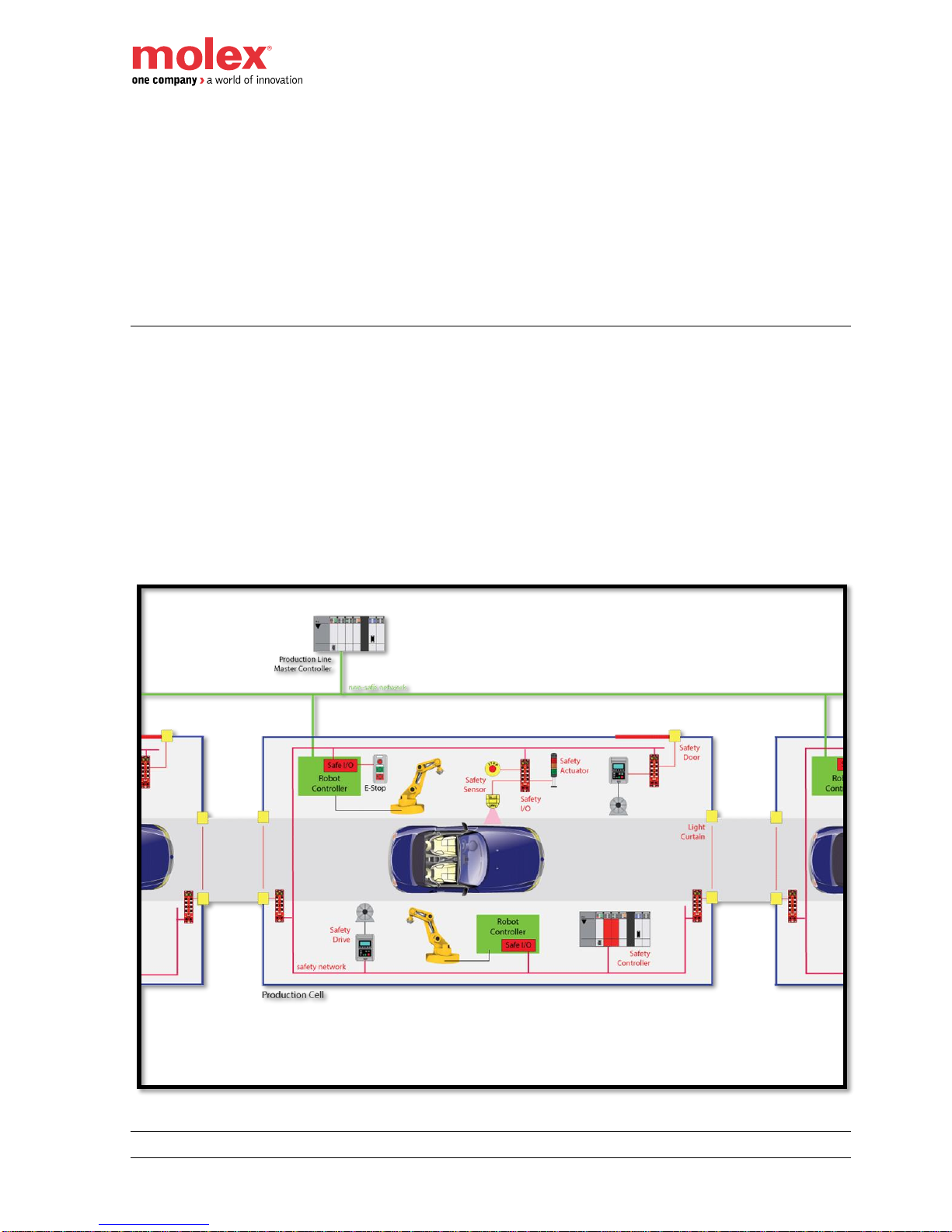
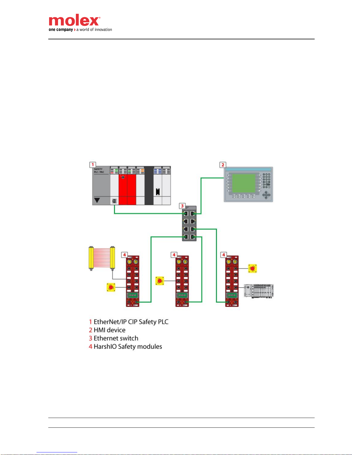
EtherNet/IP™ CIP Safety™ HarshIO module serves mainly applications for automotive manufacturers and
machine builders looking for on-machine safety I/O connection to reduce cabinet space. The IP67 60mm
housing with M12 connectors make HarshIO modules ideally suited for many safety applications including
material handling equipment, automated assembly machinery and automotive applications running robots into
cells.
- Example of safety application used for automotive assembly line -
Page 17
EtherNet/IP™ CIP Safety™ IP67 HarshIO 600
17 IP67 Safety Digital I/O Modules
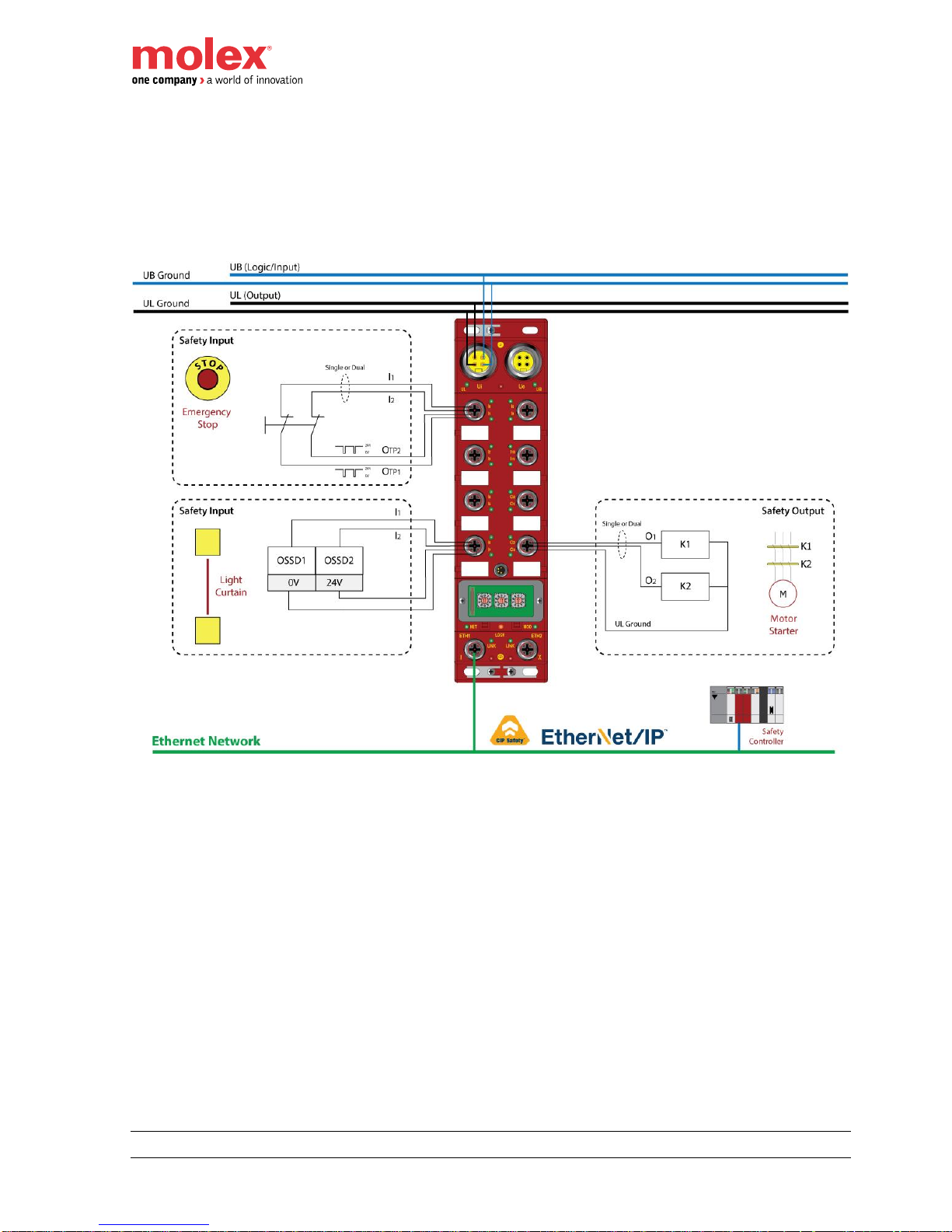
The combination of EtherNet/IP and CIP Safety protocols allow exchanging safety process I/O and diagnostics
information over a single Ethernet network. The modules need to be configured in order to suit with the safety
function definitions, up to SIL 3 as defined by IEC 61508 or CAT 4/ PLe as defined by ISO 13849-1 (in
particular, inputs and outputs could be set for use as dual-channel).
The diagram below shows some examples of safety I/O wirings.
Page 18
EtherNet/IP™ CIP Safety™ IP67 HarshIO 600
18 IP67 Safety Digital I/O Modules
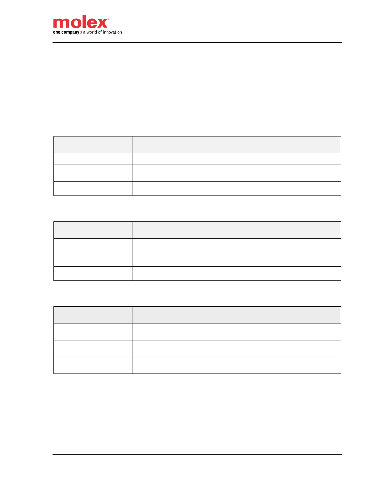
Functional safety - safety relevant parameters
This chapter describes parameters associated to functional safety. In according to IEC 61508, Safety means
first that a system is free from unwarrantable risks. Functional safety is a part of the total safety, which
guarantees the fail-safe response of a safety system according to the input conditions. Here internal safetyrelevant device errors must be detected and lead to a safe condition.
Safety relevant parameters may always be found in the according manuals of the modules.
TCDEC-8B4P-D1U-Gx and TCDEC-8B4P-DYU-Gx products:
Parameters according to
IEC 61508
Meaning
PFH = 1 *10
-10
/h
Probability of failure per Hour: Probability of danger failure per hour
PFDavg = 8.74 * 10
-06
Probability of Failure on Demand average: Average of probability of failure on
demand
SFF according SIL 3
Safe Failure Fraction: Fraction of failure, which lead to a safe state.
TCDEC-8B4P-D1U-Gx and TCDEC-8B4P-DYU-Gx products:
Parameters according to
IEC 61508
Meaning
PFH = 8.67 *10
-11
/h
Probability of failure per Hour: Probability of danger failure per hour
PFDavg = 7.65 * 10
-06
Probability of Failure on Demand average: Average of probability of failure on
demand
SFF according SIL 3
Safe Failure Fraction: Fraction of failure, which lead to a safe state.
All products:
Parameters according to
DIN EN ISO 13849-1
Meaning
MTTFd: High
Mean Time To dangerous Failure
DCavg: High
Diagnostic Coverage average
Service Life: 20 years
During the expected life of the device of up to 20 years, no proof test is
required
Page 19

EtherNet/IP™ CIP Safety™ IP67 HarshIO 600
19 IP67 Safety Digital I/O Modules
Product environmental and safety instructions
Approvals, directives, standards
The HarshIO safety module has been designed to comply with the following directives and standards:
Conformity and approval
CE*
2006/42/EC
Machinery directive
2011/65/UE
RoHS 2 directive
2014/30/EU
EMC directive for industrial use (Class-B)
UL Listed
UL 508
Approval for USA and Canada
IEC 61508
Ed 2010
Functional Safety of
Electrical/Electronic/Programmable Electronic
Safety-related Systems (E/E/PE, or E/E/PES)
ISO 13849-1
Ed 2015
Safety of machinery
IEC 62061
Ed 2012
Safety of machinery: Functional safety of
electrical, electronic and programmable
electronic control systems
IEC 61131-2
Ed 2007
Programmable logic controllers - Equipment
Requirements and Tests
ODVA conformance
Vol 2 – 1.18
EtherNet/IP™
Vol 5 – 2.6
CIP Safety™
IEC 60529
Ed 2010
IP67 degree of protection
*CE Declaration of conformity can be found in section ‘Certifications’ of this manual
The HarshIO has been designed and produced specifically for:
communication and process control
general control and automation applications
industrial applications
operation within the environmental conditions specified in the technical data
This product was EMC tested for use in industrial areas. If it is to be used in personal or business and trade
environments, the resulting system must go through EMC qualification.
Page 20
EtherNet/IP™ CIP Safety™ IP67 HarshIO 600
20 IP67 Safety Digital I/O Modules
Explosive environments
Danger!
This device is not certified for applications in
explosive environments (EX-zone)
Power supply and Electrical safety
The device is developed for operation on 24 VDC power supplies, which correspond to the PELV-/SELV
regulations in accordance to EN 50178.
Risk of injury by electric current!
There may only devices be connected to the module, which have a safe separation
from the mains (such as 120V/230V/600V) power.
The power supply to generate 24 V power must correspond to the requirements for
PELV/SELV according to EN 50178.
IP67 rating
The product complies with IP67 when installed. All caps of non-used connectors shall be mounting on the
product to maintain the IP67 rating during operation.
Danger!
Risk of electric power!
Contact with live parts is immediate danger to life.
Mission time
The expected life time of the HarshIO module is up to 20 years with no proof test necessary.
Warning!
If the user calculates their safety application with the specified data for >20 years, the
HarshIO has to be decommissioned and replaced. A proof test cannot be established
by the user.
Earthing
Warning!
Connections to earth shall be wired accordingly to the relevant chapter of this manual in
order to warrant EMC characteristics of the product.
Page 21
EtherNet/IP™ CIP Safety™ IP67 HarshIO 600
21 IP67 Safety Digital I/O Modules
Product features
EtherNet/IP CIP Safety HarshIO main features include:
Safety Inputs
o To connect safety devices, such as emergency stop push buttons, gate switches, and safety light
curtains.
o Single or dual channel modes supported.
o Dual-channel mode evaluates consistency between two input signals (channels), which allows
use of the module for Safety Category 3 and 4. The time of a logical discrepancy between two
channels can be monitored using a discrepancy time setting.
o Each safety input has its own associated test output to check external wiring short-circuit.
o Independently adjustable ON and OFF delay are available per channel.
Test Outputs
o Separate test outputs are provided for external short circuit detection of a safety input.
o Power (24 V) can be supplied to devices, such as safety sensors.
o Test outputs can be configured as standard non-safe outputs.
o 2 test outputs can be used for broken wire detection of a muting lamp.
Safety Outputs or Bipolar Safety Outputs
o Up to 1A for safety outputs and up to 2A for bipolar per output point.
o Dual-channel mode evaluates consistency between two output signals (channels).
o Safety outputs can be pulse tested to detect field wiring shorts to 24 VDC.
o Bipolar safety outputs use pulse testing to detect a short to 24 VDC on the safety sourcing output,
and a short to 0VDC on the safety sinking output.
I/O Safety RPI with up to 10ms cycle time
IP67 rated enclosure that when properly installed provides protection against the ingress of dust, water
Integrated 2-port unmanaged Ethernet switch with cross-over and DLR capability
Isolated grounding to able to use 2 separate power supplies to energize the module logic/inputs and
outputs.
Protective earth (for power supplies)
Functional earth (for Ethernet connectors)
Diagnostic visible LEDs
Easy commissioning via Molex Safety Network Configuration Tool (SNCT)
On-board memory key (Window or M8 versions) allowing to store module configuration and perform
replacement in few minutes without any special tool or re-commissioning.
3 rotary switches to set IP address
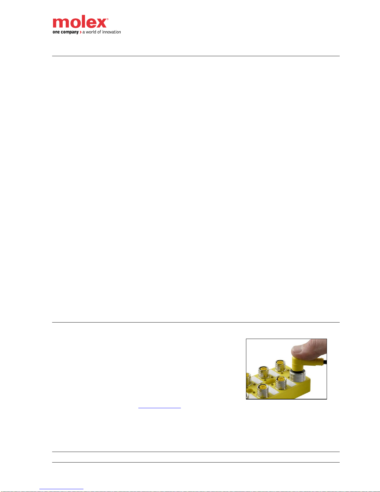
Ultra-Lock M12 connectivity
HarshIO safety modules with Micro-Change® (M12) ports accept both
threaded cordsets and Molex Ultra-Lock™ system.
Ultra-Lock™ connection System! The fastest, easiest and most secure
connection ever designed. Ultra-Lock™ technology is designed for
higher performance and reliability.
Discover how the push-to-lock technology of the Ultra-Lock connection
system can eliminate the downtime, increase the productivity and lower
the costs. More information visit: www.molex.com.
Page 22

EtherNet/IP™ CIP Safety™ IP67 HarshIO 600
22 IP67 Safety Digital I/O Modules
Ordering information
This user safety manual applies to the following HarshIO product references:
Part Number Table
4-pin 7/8” power connector versions
SAP No
Material No
Description
112095-5107
TCDEC-8B4P-DYU-GW
EtherNet/IP CIP Safety IP67 module, 4-pin power connector,
12 Safety Inputs + 4 Safety Outputs, Windows key
112095-5127
TCDEC-8B4P-DYU-G8
EtherNet/IP CIP Safety IP67 module, 4-pin power connector,
12 Safety Inputs + 4 Safety Outputs, M8 key
112095-5108
TCDEC-8B4B-DYU-GW
EtherNet/IP CIP Safety IP67 module, 4-pin power connector,
12 Safety Inputs + 2 Safety Bipolar Outputs, Windows key
112095-5128
TCDEC-8B4B-DYU-G8
EtherNet/IP CIP Safety IP67 module, 4-pin power connector,
12 Safety Inputs + 2 Safety Bipolar Outputs, M8 key
5-pin 7/8” power connector versions
SAP No
Material No
Description
112095-5111
TCDEC-8B4P-D1U-GW
EtherNet/IP CIP Safety IP67 module, 5-pin power connector,
12 Safety Inputs + 4 Safety Outputs, Windows key
112095-5129
TCDEC-8B4P-D1U-G8
EtherNet/IP CIP Safety IP67 module, 5-pin power connector,
12 Safety Inputs + 4 Safety Outputs, M8 key
112095-5112
TCDEC-8B4B-D1U-GW
EtherNet/IP CIP Safety IP67 module, 5-pin power connector,
12 Safety Inputs + 2 Safety Bipolar Outputs, Windows key
112095-5130
TCDEC-8B4B-D1U-G8
EtherNet/IP CIP Safety IP67 module, 5-pin power connector,
12 Safety Inputs + 2 Safety Bipolar Outputs, M8 key
Page 23
EtherNet/IP™ CIP Safety™ IP67 HarshIO 600
23 IP67 Safety Digital I/O Modules
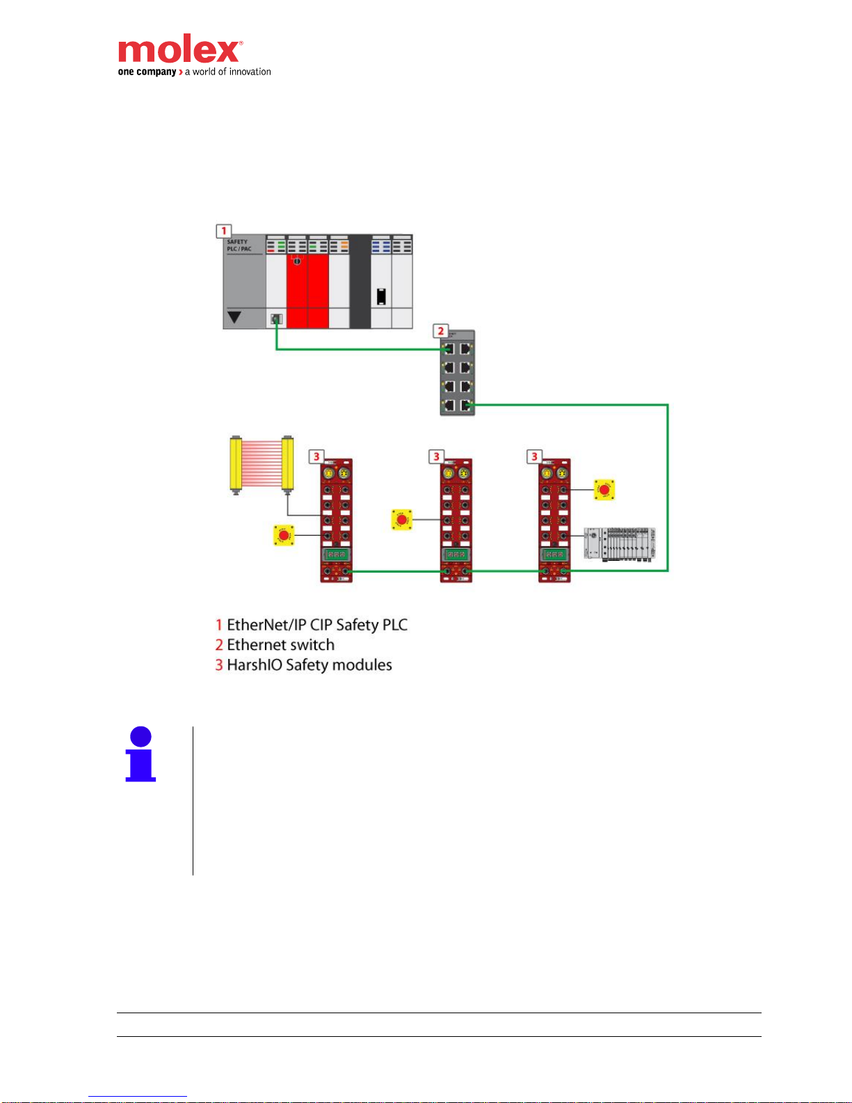
Ethernet topologies
EtherNet/IP CIP Safety HarshIO IO module can be used with a protocol compliant scanner as part of control
system architecture. The modules built-in 2-port Ethernet DLR capable switch allowing to use the network
topology that meets the application needs. These topologies include the following:
Star
Daisy-chain
Combination of star and daisy-chain
DLR for Ethernet media ring redundancy
Star topology
Star topology allows to connect mixed I/O modules or additional devices. Performing maintenance on one
module – for example, by removing the network cable, or by cycling power to the module – does not affect
other modules.
Page 24
EtherNet/IP™ CIP Safety™ IP67 HarshIO 600
24 IP67 Safety Digital I/O Modules
Daisy-chain topology
Daisy-chain ring topology is the easiest way to add more EtherNet/IP CIP Safety HarshIO IO module or
additional devices in the system by daisy-chaining, or connecting each industrial device in series to the next.
This topology is the simplest and cost-effective solution because it takes full advantage of the dual port
Ethernet switch integrated in HarshIO modules and reduces the overall Ethernet cable length.
Note!
When considering the daisy chain topology, note that:
Performing maintenance on any module not physically located at the end of the
daisy chain – for example, by removing the network cable, or by cycling power to
the module – affects any modules located down the chain from the maintained
module.
The embedded dual port Ethernet switch located in each module eliminates the
need for additional Ethernet switches
Page 25
EtherNet/IP™ CIP Safety™ IP67 HarshIO 600
25 IP67 Safety Digital I/O Modules
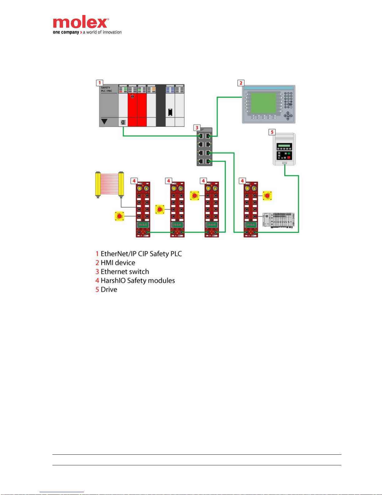
Combination of star and daisy-chain topology
Combining star and daisy-chain topology allows connecting EtherNet/IP CIP Safety HarshIO IO modules with
mixed HarshIO modules or additional devices.
Page 26
EtherNet/IP™ CIP Safety™ IP67 HarshIO 600
26 IP67 Safety Digital I/O Modules
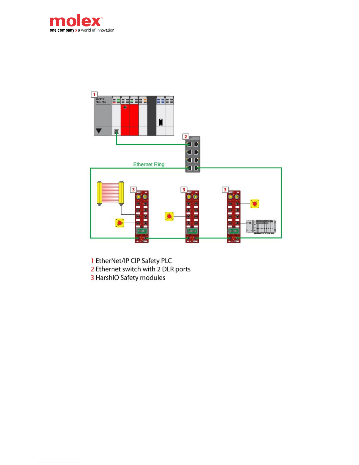
DLR Ring topology
DLR ring topology allows including mixed I/O modules and additional devices in a ring. Performing
maintenance on one module – for example, by removing the network cable, or by removing a module does not
affect other modules as the disruption can be detected and the CIP safety communication can be then routed
adequately.
Page 27
EtherNet/IP™ CIP Safety™ IP67 HarshIO 600
27 IP67 Safety Digital I/O Modules
4. Functional Safety Functions
EtherNet/IP CIP Safety HarshIO modules can achieve the following safety classes by making suitable
parameter settings and wiring.
Safety Classes
I/O Configuration
Per IEC 61508 / IEC 62061
Per ISO 13849-1
Dual I/O Channel
SIL 3
PL e / Cat. 4
Single I/O Channel
SIL 2
PL d / Cat. 2
Safety States
The safety states of the HarshIO module are defined as the following:
Safe Outputs are switched OFF
Safe Inputs are reported in the OFF state on the network
Warning!
HarshIO modules are to be used in systems where the OFF state is the safety state.
Page 28
EtherNet/IP™ CIP Safety™ IP67 HarshIO 600
28 IP67 Safety Digital I/O Modules
Safety Inputs
Safety inputs are used to report the state of safety input devices.
A safety input can be configured as:
Not Used (default) - the input is disable and doesn’t participate in any safety function
Safety - the input participates to the safety function, but does not have a dependency on a test output
Safety Pulse Test - the input participates to the safety function and has a dependency on an
associated test output configured as “Pulse Test”
Standard - The input doesn’t participate in any safety function (allows to connect non-safe input
device). Nevertheless a Standard input behaves exactly like an input configured as Safety.
Using Safety Inputs on Single-Channel
The inputs are configured as 2 distinct safety inputs on the same M12 connector.
The process Input value is set to safety device physical input value and status is “1” (good) as long as no fault
is detected. On fault detection, the process Input value is turned OFF and status is “0” (bad).
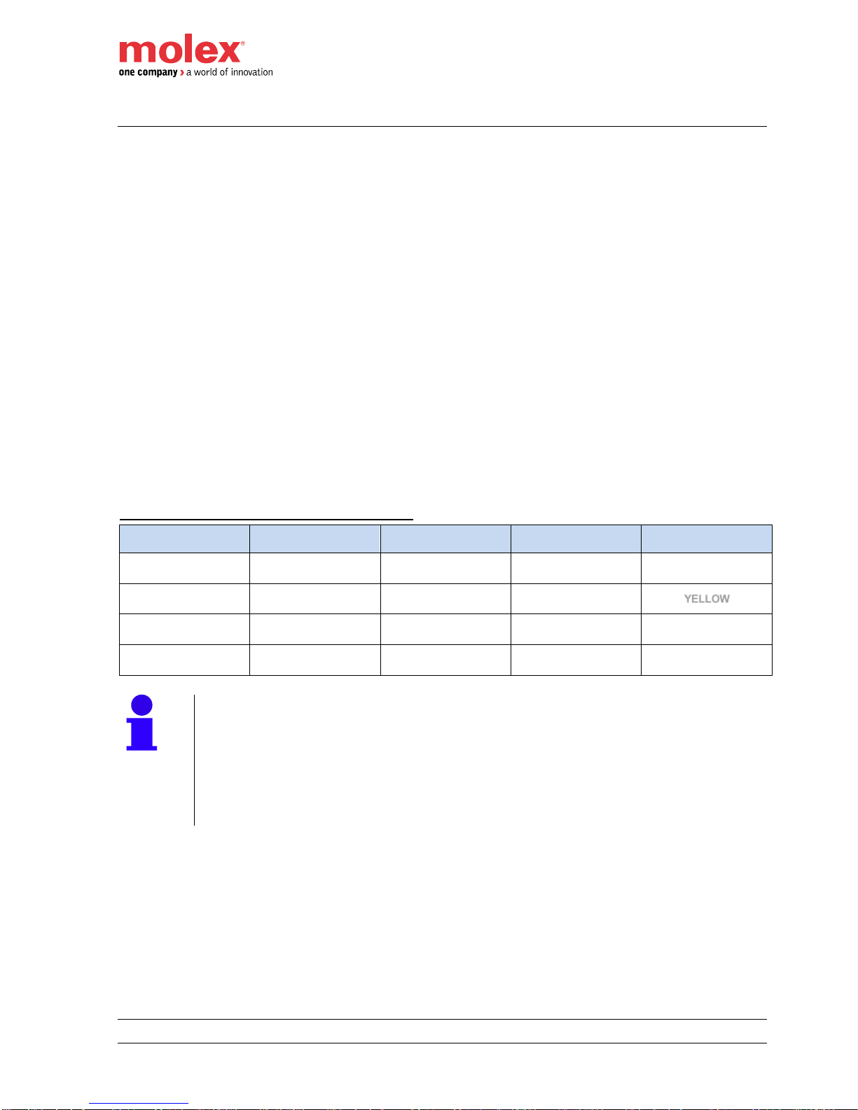
HarshIO behavior when used as single safe inputs:
Safety Device
Physical State
Fault Detected
(1)
Safe Input
Process Value
Safe Input
Process Status
Safe Input
Led Status
0 = OFF
No
0 (safe)
1
OFF
1 = ON
No
1 (active)
1
YELLOW
0 = OFF
Yes
0 (fault)
(2)
0
RED
1 = ON
Yes
0 (fault)
0
RED
Notes!
(1) When single channel input is configured as “Standard” or “Safety”, only internal
hardware faults can be detected. Input shall be configured as “Safety Pulse Test” to
allow external short to ON detection.
(2) This state is a transitory state only as it corresponds to fault reset condition
(physical value set to OFF). If physical fault still exist on the wiring, fault will be
detected again at next ON transition.
Page 29
EtherNet/IP™ CIP Safety™ IP67 HarshIO 600
29 IP67 Safety Digital I/O Modules
Using a Test Output
A test output can be configured as
Pulse Test – When the external contact of the safety device is closed, the test output pulse allows
diagnosing external wiring faults as stuck with the power supply or short with the other safety input
from the same M12 connector.
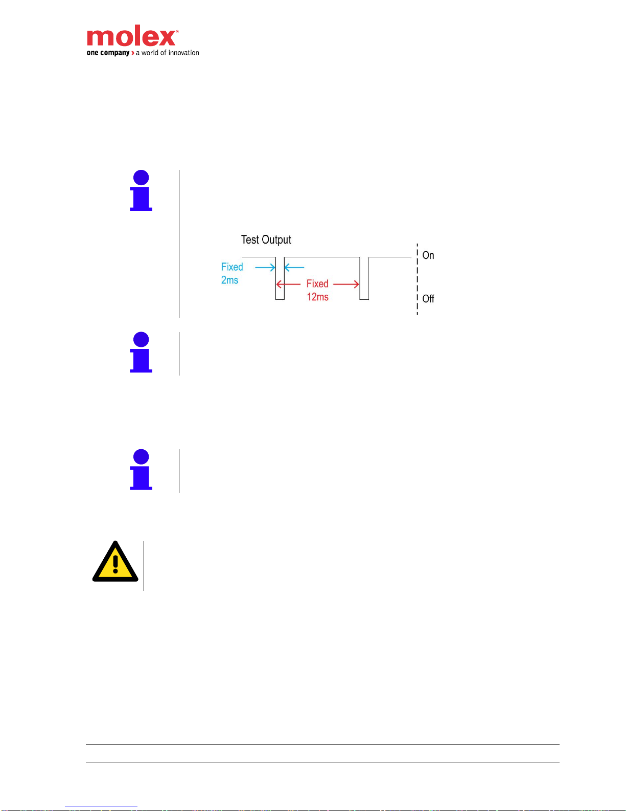
Note!
Characteristics of the pulse test
Pulse test length: 2ms
Pulse test period: 12ms
Note!
A pulse test can be configured to each safety Input of the M12 connector. It can
be also associated to the both inputs.
Power Supply – The test output is used as a power supply to supply 24 VDC for the safety input
device.
Standard – The test output is used as a non-safe digital output.
Note!
No status led is associated to test outputs. Test output values and status can
nevertheless be monitored via Inputs process image.
Muting Lamp – The test output diagnoses whether the circuit and lamp are operational.
Warning!
When test outputs are configured for Power Supply or Muting Lamp, the use of
double isolation cable could be required depending on the application and on the
expected SIL/CAT to achieve.
Page 30
EtherNet/IP™ CIP Safety™ IP67 HarshIO 600
30 IP67 Safety Digital I/O Modules
When test output is activated, Muting Lamp feature controls the output current. Below 5mA, a fault is
detected and the status is 0=OFF. Above 25mA is normal operation, the status is 1=ON.
Below is a typical scenario for muting lamp broken wire detection:
Test Output Process Value
Muting Lamp Physical State
Muting Lamp Status
Step #1: 1 = ON
Lamp good
1
Step #2: 1 = ON
Lamp broken
0
Step #3: 0 = OFF
Lamp broken
0
Step #4: 0 = OFF
Lamp replaced
1
Notes!
Only Test Output 3 and Test Output 7 can be configured in Muting Lamp
mode.
When Test Output is not activated, no broken wire fault can be detected.
However, once a default has been detected (step 2), the lamp
replacement is diagnosed even if the Test Output is deactivated (step 3)
Broken wire detection is performed at a 3 second period. Two
consecutive detections are required before the status is reported as BAD,
so up to 6 seconds can be required before muting lamp status to be set to
BAD
Typical wiring of safety inputs
M12 pining and wiring of the safety inputs with the associated pulse test outputs
1: Test Output #1 (TP1, 24 VDC powered from UB)
2: Safe Input #1 (IN1)
3: Ground Logic/Input (UB GND)
4: Safe Input #0 (IN0)
5: Test Output #0 (TP0, 24 VDC powered from UB)
1
1 2
3
4
5
External Contact
TP0
IN0
IN1TP1
GND
External Contact
Page 31

EtherNet/IP™ CIP Safety™ IP67 HarshIO 600
31 IP67 Safety Digital I/O Modules
Set Dual-channel Mode and Discrepancy Time
To support redundant channel safety devices, the consistency between signals on two input channels can be
evaluated. This type of redundant wiring is called dual-channel mode.
Note!
The dual-channel feature can only work by using the 2 safety input signals of the
same M12 port of the HarshIO.
A total of six redundant channel safety devices can be connected to the HarshIO.
One redundant channel safety device per M12 port.
Either “Equivalent” or “Complementary” evaluation mode of the safety input pair has to be selected. In dualchannel mode, the HarshIO module monitors the time during which there is a discrepancy between the two
channels.
Note!
Using the HarshIO SNCT software,
The discrepancy time can be configured from 10ms to 30s, in increments of 10ms.
The discrepancy time default value is 10ms.
HarshIO behavior when used as equivalent dual safe inputs:
Safety Device
Physical State
Fault Detected
(*1)
Safe Input
Process Value
Safe Input
Process Status
Safe Input
Led Status
Input
(Pin 4)
Input+1
(Pin2)
Input
Input+1
Input
Input+1
Input
Input+1
Input
Input+1
0 = OFF
0 = OFF
No
No
0 (safe)
0 (safe) 1 1
OFF
OFF
0 = OFF
1 = ON
No
No
0 (fault)
0 (fault)
0
(a)
0
(a)
RED
(b)
RED
(b)
1 = ON
0 = OFF
No
No
0 (fault)
0 (fault)
0
(a)
0
(a)
RED
(b)
RED
(b)
1 = ON
1 = ON
No
No
1 (active)
1 (active) 1 1
YELLOW
YELLOW
- - Yes
-
0 (fault)
0 (fault) 0 0
RED
BLINKING
RED
- - -
Yes
0 (fault)
0 (fault) 0 0
BLINKING
RED
RED
(a): At “1” until discrepancy time expired.
(b): OFF until discrepancy time expired.
HarshIO behavior when used as complementary dual safe inputs:
Safety Device
Physical State
Fault Detected
(1)
Safe Input
Process Value
Safe Input
Process Status
Safe Input
Led Status
Input
(Pin 4)
Input+1
(Pin2)
Input
Input+1
Input
Input+1
Input
Input+1
Input
Input+1
0 = OFF
0 = OFF
No
No
0 (fault)
1 (fault)
0
(a)
0
(a)
RED
(b)
RED
(b)
0 = OFF
1 = ON
No
No
0 (safe)
1 (safe) 1 1
OFF
YELLOW
1 = ON
0 = OFF
No
No
1 (active)
0 (active) 1 1
YELLOW
OFF
1 = ON
1 = ON
No
No
0 (fault)
1 (fault)
0
(a)
0
(a)
RED
(b)
RED
(b)
- - Yes
-
0 (fault)
1 (fault) 0 0
RED
BLINKING
RED
- - -
Yes
0 (fault)
1 (fault) 0 0
BLINKING
RED
RED
(a): At “1” until discrepancy time expired.
(b): OFF until discrepancy time expired.
Page 32

EtherNet/IP™ CIP Safety™ IP67 HarshIO 600
32 IP67 Safety Digital I/O Modules
Notes!
(1) When dual channel inputs are configured as “Standard” or “Safety”, only internal
hardware faults and discrepancy between inputs can be detected. Inputs shall be
configured as “Safety Pulse Test” to allow external short to 1 detection
At inputs transition, during the discrepancy time, inputs are reported at the safe
state
Safety Input Fault Recovery
Note!
If a fault is detected, the safety input (or safety inputs) process value remains in the
safety state until the following procedure is applied:
1. Removed the cause of the fault.
2. Set the safety input to his safety state.
Input Delay
On-delay and Off-delay can be configured individually for each input.
On-delay
The On-delay is the minimum time necessary for a physical input switched to ON to be reported as “1” on the
network. For example, if the On-delay is set to 5ms, the Input will be reported on the network at level “1”, after
the Input has been evaluated at ON during at least 5ms.
Off-delay
The Off-delay is the minimum time necessary for a physical input switched to OFF to be reported as “0” on the
network. For example, if the Off-delay is set to 5ms, the Input will be reported on the network at level “0”, after
the Input has been evaluated at OFF during at least 5ms.
Note!
Using the HarshIO SNCT software,
On-delay and Off-delay parameters can be configured from 0 to 1000ms, in
increments of 1ms.
On-delay and Off-delay default values are 0.
Input Error Latch Time
The Input Error Latch Time is a unique parameter that applies for all the Inputs.
The purpose for latching input errors is to make sure that intermittent faults that can only exist for a few
milliseconds are latched long enough to be read by the controller. It defines the minimal duration a detected
fault on any safe inputs shall be reported on the network in order to able the controller to detect it.
Note!
Using the HarshIO SNCT software,
Input Error Latch Time default parameters can be configured from 0 to 65530ms, in
increments of 10ms.
Input Error Latch Time default value is 1000ms.
The amount of time to latch the error must be based on the RPI of the safety
connection, the application safety task watchdog, and other application specific
variables.
Page 33

EtherNet/IP™ CIP Safety™ IP67 HarshIO 600
33 IP67 Safety Digital I/O Modules
Safety Sourcing Outputs (TCDEC-8B4P-D1U-Gx and TCDEC-8B4P-DYU-Gx)
Safety sourcing outputs are used to drive the state of output devices.
Note!
HarshIO safe outputs are:
current sourcing at max. 1A
short circuit protected
pulse test configurable
A Safety Output can be configured as:
Not Used (default) - The output is disable and doesn’t participate in any safety function.
Safety Pulse Test - The output generates pulse tests (when the output is active) to monitor short-
circuit between output pin and power supply (stuck at “1”), or short with other active output from the
same M12 connector.
Notes!
Using the HarshIO SNCT software,
The Pulse tests length is configurable from 300µs to 10ms, in increments
of 100µs.
Pulse tests length default value is 500µs
Pulse tests period: 468ms
In addition to external shorts detection, all safety functions involved in
outputs switch-off are also diagnosed at each period. So a series of 4
pulse tests are applied on each safety output.
Note!
The pulse test should be configured according to the impedance of the connected
device. HarshIO safety has been design to control a wide range of device by using
an active discharge circuit. For each pulse test higher than 500µs (or equal), if a
residual voltage is present, a 50mA current is clamped during 300µs.
Nevertheless, if it is not enough and output goes into safe state due to the
capacitive load of the connected equipment, the pulse length can be increased (up
to 10ms).
Page 34

EtherNet/IP™ CIP Safety™ IP67 HarshIO 600
34 IP67 Safety Digital I/O Modules
Notes!
Safety Sourcing outputs should not be used to provide power to a device
or sub-system whom the resistive and capacitive load could vary during
operation.
Warning!
Be careful of the response time of the output device to prevent any malfunction
because of pulse test.
Safety No Pulse Test - The output is used without pulse test.
Note!
In this mode, diagnostics are done on the output. When a sourcing output is
switched off, the measured state can be different to the expected one due to the
capacitive load of the connected equipment. HarshIO have been design to control
a wide range of equipment by using an active discharge circuit. When a sourcing
output is switched off, if a residual voltage is present, a 50mA current is clamped
during 2ms.
M12 pining and wiring of the safety sourcing outputs:
1: 24 VDC (powered from UL)
2: Safe Output #1 (OUT1)
3: Ground Output (UL GND)
4: Safe Output #0 (OUT0)
5: Ground Output (UL GND)
Note!
The maximum current available on the Pins #1 (24 VDC) of the 2 Output sourcing ports
is 3.5A.
1
1 2
34
5
External Load
OUT0
OUT1
GND
External Load
GND
24V
Page 35

EtherNet/IP™ CIP Safety™ IP67 HarshIO 600
35 IP67 Safety Digital I/O Modules
Using Safety Sourcing Outputs in Single-Channel Outputs
Outputs from the same M12 connector are configured as 2 single channel outputs.
When activated by the logic controller, output is turned ON and status is “1” (good) as long as no fault is
detected. On fault detection, Output is forced to safe state OFF and status is set to “0” (bad).
HarshIO behavior when used as single safe outputs:
Safe Output
Process Value
Fault Detected
Safety Device
Physical State
Safe Output
Process Status
Safe Output
Led Status
0
No
0 = OFF (safe)
1
OFF
1
No
1 = ON (active)
1
YELLOW
-
Yes
(on output itself)
0 = OFF (fault)
0
RED
-
Yes
(on the partner)
0 = OFF (fault)
0
BLINKING RED
Note!
When a fault is detected on a single channel output, both outputs on the same M12
connector will switch to safe state.
Note!
When no pulse test is configured on a safety output, only read back value is used to
detect fault, so only short to 1 when output is driven to 0 and short to 0 when output
is driven to 1 are detected
When pulse tests are activated, internal faults as well as short to 1 can be then
detected
Using Safety Outputs as Dual-Channel outputs
Outputs from the same M12 connector can be configured as an output pair.
When both output process values are activated by the logic controller, the dual outputs are turned ON and
status is “1” (good) as long as no fault is detected. On hardware fault detection or discrepancy of output
process values, outputs are forced to safe state OFF and status is set to “0” (bad).
HarshIO behavior when used as dual safe outputs:
Safe Output
Process Value
Fault Detected
Safety Device
Physical State
Safe Output
Process Status
Safe Output
Led Status
Output
Output+1
Output
Output+1
Output
(Pin 4)
Output+1
(Pin2)
Output
Output+1
Output
Output+1
0
0
No
No
0 = OFF
(safe)
0 = OFF
(safe)
1 1 OFF
OFF
0
1
No
No
0 = OFF
(fault)
0 = OFF
(fault)
0 0 RED
RED
1
0
No
No
0 = OFF
(fault)
0 = OFF
(fault)
0 0 RED
RED 1 1
No
No
1 = ON
(active)
1 = ON
(active)
1
1
YELLOW
YELLOW
- - Yes
-
0 = OFF
(fault)
0 = OFF
(fault)
0 0 RED
BLINKING
RED
- - -
Yes
0 = OFF
(fault)
0 = OFF
(fault)
0
0
BLINKING
RED
RED
Page 36

EtherNet/IP™ CIP Safety™ IP67 HarshIO 600
36 IP67 Safety Digital I/O Modules
Safety Output Fault Recovery
Note!
If a fault is detected, the safety output (or safety outputs) physical value remains in the
safety state until the following procedure is applied:
Removed the cause of the fault.
Set the safety output to his safety state.
Output Error Latch Time
The Output Error Latch Time is a unique parameter that applies for all the Outputs.
The purpose for latching output errors is to make sure that intermittent faults that can only exist for a few
milliseconds are latched long enough to be read by the controller. It defines the minimal duration a detected
fault on any safety outputs shall be reported on the network in order to able the controller to detect it.
Note!
Using the HarshIO SNCT software,
Output Error Latch Time default parameters can be configured from 0 to 65530ms,
in increments of 10ms.
Output Error Latch Time default value is 1000ms.
The amount of time to latch the error must be based on the RPI of the safety
connection, the application safety task watchdog, and other application specific
variables.
Page 37

EtherNet/IP™ CIP Safety™ IP67 HarshIO 600
37 IP67 Safety Digital I/O Modules
Bipolar Safety Outputs (TCDEC-8B4B-D1U-Gx and TCDEC-8B4B-DYU-Gx)
Bipolar safety outputs are used to drive the state of output devices.
The bipolar outputs combines the safety sourcing output and the safety sinking output of the same M12
connector as a output pair in dual channel mode and can support current up to 2A.
Note!
HarshIO bipolar safety outputs are:
current sourcing at max. 2A.
always configured in dual-channel mode meaning that a maximum of two safety
output devices can be connected to a HarshIO module.
short circuit protected
A bipolar Safety Output can be configured as:
Not Used (default) - The bipolar outputs are disable and don’t participate in any safety function.
Safety Pulse Test - The output sourcing generates a pulse test (when the output is active) to monitor
short-circuit between output sourcing signal and power supply (stuck at “1”). The output sinking
generates a pulse test (when the output is active) to monitor short-circuit between output sinking signal
and ground (stuck at “0”).
Note!
Using the HarshIO SNCT software,
Each safety bipolar output pair can be configured individually with or
without pulse test.
The Pulse test length is configurable from 300µs to 10ms, in increments
of 100µs, with a default value of 700µs. In the case of bipolar outputs,
pulse management has been designed in order that the default value
should work in almost applications, including applications where the
resistive and capacitive load of the connected device or sub-system can
vary during operation. It is then strongly recommended to keep default
value unchanged. Changing this parameter should be done only if an
issue is observed during application testing.
Pulse test period: 468ms
In addition to external shorts detection, all safety functions involved in
outputs switch-off are also diagnosed at each period. So a series of 4
pulse tests are applied on each safety output.
Page 38

EtherNet/IP™ CIP Safety™ IP67 HarshIO 600
38 IP67 Safety Digital I/O Modules
Note!
The pulse test should be configured according to the impedance of the connected
device. HarshIO safety bipolar output has been design to control a wide range of
device by using an active discharge circuit. For each pulse test higher than 700µs
(or equal), if a residual voltage is present, a 50mA current is clamped during
500µs. Nevertheless, if it is not enough and output goes into safe state due to the
capacitive load of the connected equipment, the pulse length can be increased (up
to 10ms).
Safety No Pulse Test - The bipolar output is used without a pulse test.
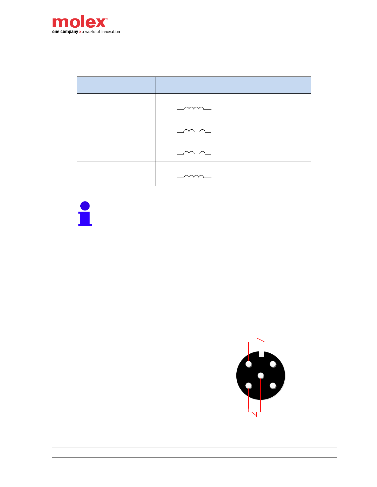
M12 pining and wiring of the safety bipolar outputs:
1: 24 VDC (powered from UL)
2: Safety Output #1 (OUT1 - Sinking)
3: Ground Output (UL GND)
4: Safety Output #0 (OUT0 - Sourcing)
5: Ground Output (UL GND)
Note!
The maximum current available on the Pins #1 (24 VDC) of the 2 Output bipolar ports is
3.5A.
Danger!
Load(s) shall never be connected between Pin 4 (sourcing output) and GND as well as
between Pin 2 (sinking output) and 24 V.
24 V and GND pins shall only be used to provide power to external device but shall
never been wired in association with a safety output.
Note!
A frequent use of bipolar safety outputs is to power and Molex non-safe HarshIO
modules from the bipolar M12 connector.
A special M12 – Mini change cable can be ordered for easy wiring. In this case:
UB (logic and Input) of the non safe module are powered by the 24 V (pin 1) of
the bipolar connector.
UL (Output) of the non-safe module is directly switched on/switched off by the
bipolar pair (pin 2 and 4).
1
1 2
34
5
OUT0
OUT1
GND
External Load
24V GND
Page 39

EtherNet/IP™ CIP Safety™ IP67 HarshIO 600
39 IP67 Safety Digital I/O Modules
I/O Status
HarshIO safety module provides status information to monitor the I/O circuit. The status information can be
read by the EtherNet/IP scanner.
Note!
When a fault is detected, the status value is “0” meaning bad. On normal operation, the
status value is “1” meaning good.
Each individual point listed below has its own individual status:
Safety Input Status
Test Output Status
Safety Output Status (sourcing or bipolar)
Behavior in case of fault
Detected fault
Fail safe state
applied on
Method to recover
Fieldbus
communication
availability
Safety Input pulse test
failure
(single channel)
Faulted safe input
1. Remove the fault
2. Switch input in the safe state
Yes
Wait latch error time expired
Safety Input pulse test
failure
(dual channel)
Safety inputs pair
1. Remove the fault
2. Switch input in the safe state
Yes
Wait latch error time expired
Safety input pair
discrepancy
(dual channel)
Safety inputs pair
1. Remove the fault
2. Switch input in the safe state
Yes
Wait latch error time expired
Safety output pulse test
failure or read back value
error
(single channel)
Both single safety
outputs on same
connector
1. Remove the fault
2. Switch outputs in the safe state
Yes
Wait latch error time expired
Safety output pulse test
failure or read back value
error
(dual channel)
Safety output pair
1. Remove the fault
2. Switch outputs in the safe state
Yes
Wait latch error time expired
Safety output discrepancy
error
(dual channel)
Safety Output pair
1. Remove the fault
2. Switch outputs in the safe state
Yes
Wait latch error time expired
Page 40

EtherNet/IP™ CIP Safety™ IP67 HarshIO 600
40 IP67 Safety Digital I/O Modules
Overvoltage/under
voltage error on input
power (UB)
Whole module (all
safety inputs and
outputs)
Power cycle needed
Yes
Overvoltage error on
output power (UL)
Whole module (all
safety inputs and
outputs)
Power cycle needed
Yes
Under voltage error on
output power (UL)
All Safety outputs
1. Remove the fault
2. Switch outputs in the safe state
Yes
Overcurrent on input
power (UB)
Whole module (all
safety inputs and
outputs)
Power cycle needed
Yes
Overcurrent on output
power (UL)
Whole module (all
safety outputs)
Power cycle needed
Yes
Temperature error
Whole module (all
safety inputs and
outputs)
Power cycle needed
NO Critical Error
All I/O leds blinked
Internal hardware error
(CPU, RAM, ADC
3,3V,…)
Whole module (all
safety inputs and
outputs)
Power cycle needed
NO Critical Error
All I/O leds blinked
CIP Safety
communication error
(input connection)
All safety inputs
Originator to restart connection
Yes
CIP Safety
communication error
(output connection)
All safety outputs
Originator to restart connection
Yes
Rotary Change Value
Whole module (all
safety inputs and
outputs)
Power cycle needed
Yes
Remove External Key
Whole module (all
safety inputs and
outputs)
Power cycle needed
Yes
Page 41

EtherNet/IP™ CIP Safety™ IP67 HarshIO 600
41 IP67 Safety Digital I/O Modules
Response Time
Calculate the response time
In order to calculate the response time of a safety function, the worst-case response times of all components
involved must be added to the delays on the communication paths. Below are the response times of the
HarshIO safety modules to perform these calculations.
Warning!
The safety function is not guaranteed if the following response times are calculated
incorrectly.
1. Maximum response time of a digital safety input (single and dual-channel modes)
Calculate the maximum response time of a safety Input in error-free state. The response time is
calculated from the instant of the physical event happened to a connected sensor and the emission of
the corresponding telegram on the EtherNet/IP network by the HarshIO safety module.
Calculation Delay Times
Response time of the connected sensor/switch + _______ ms
HarshIO Input delay configured + 500μs tolerance + _______.5 ms
Internal maximum processing time of HarshIO module PTIN max + 10.5 ms
---------------------------Maximum response time of a digital safety input = _______ ms
2. Maximum response time of a digital safety output (single and dual-channel modes)
Calculate the maximum response time of a safety output in error-free state. The response time is
calculated from the moment a telegram is received by the HarshIO safety module and the actuator
physical processes the switch-off physical event.
Calculation Delay Times
Internal maximum processing time of HarshIO module PTOUT max: + 4.5 ms
HarshIO pulse test configured + _______ ms
Switch-off time of connected actuator/relay + _______ ms
Additional Switch-off delay (physical signal time commutation) + _______ ms
---------------------------Maximum response time of a digital safety output = _______ ms
Note!
The maximum response type of a detected safety error is 10ms (emission of the
corresponding telegram on the EtherNet/IP network by the HarshIO safety module).
Page 42

EtherNet/IP™ CIP Safety™ IP67 HarshIO 600
42 IP67 Safety Digital I/O Modules
5. Product Characteristics
Hardware characteristics
Type
12x Safe Inputs + 4x Safe Outputs
12x Safe Inputs +
2x Bipolar Safe Outputs
Product Reference
TCDEC-8B4P-DYU-G
TCDEC-8B4P-D1U-G
TCDEC-8B4B-DYU-G
TCDEC-8B4B-D1U-G
Safety
SIL (per IEC 61508 / IEC 62061)
Up to SIL3 (when configured in dual I/O Channel)
CAT (per ISO 13849-1)
Up to Cat. 4 (when configured in dual I/O Channel)
PL (per ISO 13849-1)
Up to PL e (when configured in dual I/O Channel)
PFH
9.70E-11
9.02E-11
PFDavg
8.47E-06
7.88E-06
DCavg
98.66%
98.58%
MTTF
679 years
851 years
Service Life
20 Years
Power
Power IN connector
Mini Change (7/8”), 4-pin or 5-pin, male, stainless steel, shielded, Maximum 8 A
Power OUT connector
Mini Change (7/8”), 4-pin or 5-pin, female, stainless steel, shielded, Maximum 8 A
Module & Input power (UB)
24 VDC, -15% / +20% (protected against power crossing).
Operating current (UB)
<100 mA
Output power (UL)
24 VDC, -15% / +20% (protected against power crossing)
Operating current (UL)
<20 mA (without load)
Safe Inputs
Channels
12 channels
Connector
M12 Ultra-Lock, 5-pin, female, A-Coded, stainless steel, unshielded
(*)
Input type
IEC61131-2 type 3
Input voltage
UB
On / Off delay
Configurable from 0 to 1000ms (0 by default)
Warning!
If UB is over 36 V for a period of 2 seconds or more. The safety module will go in fail
state (all LEDs are blinking in red) and considered as destroyed. Indeed, the internal
surge protections are irreversibly damaged and therefore the module cannot operate
anymore.
Page 43

EtherNet/IP™ CIP Safety™ IP67 HarshIO 600
43 IP67 Safety Digital I/O Modules
Pulse Test Output
Test rate interval
Max. 12ms
Pulse test length
2ms
Sensor power supply
0.7A
Max short circuit current
2A at 25°
Safe Outputs
Output type
Sourcing (PNP)
Bipolar
Channels
4 channels, 2-wires
2 channels, 2-wires
Output voltage
UL
Connector
M12 Ultra-Lock, 5-pin, female, A-Coded, stainless steel
Test rate interval
Max. 2s
Rated Output current
1A per channel
2A per channel
Maximum Short circuit current
(transitory before safety switch-off)
6.5 A
Note!
Shields of I/O connectors are not connected to earth. If shielded cable is used, then
customer should connect the cable shield to the earth.
Page 44

EtherNet/IP™ CIP Safety™ IP67 HarshIO 600
44 IP67 Safety Digital I/O Modules
Fieldbus
Ethernet connectors
M12, 4-pin, female, D-Coded, stainless steel, shielded
IP setting
DHCP based on MAC (infinite lease), DHCP based on Name, Static IP
Protocol
CIP Safety EtherNet/IP Adapter according specification Vol 5-2.6 (CIP Safety) and Vol 2 – 1.18
(EtherNet/IP)
Data access
Implicit messages for I/O data transfer
Implicit (I/O) connection
1x Exclusive Owner (EO) connection (safe information)
1x Input Only (IO) connection (to share safe process data with a non-safe scanner)
Up to 7 Listen Only (LO) (to share safe process data with a non-safe scanner)
Explicit (EM) connection
Up to 8 connections
CIP safety connection
Type 1 and Type 2
Supported CIP Objects
0x01 – Identity object
0x02 – Message Router object
0x04 – Assembly object
o Safety Input Profiles
0x20C (TO)
0x21C (TO)
0x22C (TO)
0x243 (TO)
0x25C (TO)
0x27C (TO)
o Safety Input Vendor Specific
0x300 (TO)
o Safety Output Profiles
0x233 (OT)
o Safety Output Vendor Specific
0x301 (OT)
o Configuration
0x302 (TO)
0x06 – Connection Manager object
0x23 – Safety discrete IO Profile
0x37 – File Object
0x3B – SDOP object
0x3D – SDIP object
0x3F – SDCO object
0x47 – DLR object
0x48 – QoS (Quality of Service)
0x80 – SDCI object
0xF5 – TCP/IP Interface object
0xF6 – Ethernet Link object
Integrated Switch
2x ports integrated switch
Speed: 100Mbps
Auto negotiation
Auto crossing
Auto polarity
1x status Led per port
Storm Protection against network loop (Broadcast, Multicast and Unicast packets)
Request Packet Interval (RPI)
For safety Inputs (configurable per Scanner connection) ≥10ms minimum
For safety Outputs (single Scanner connection) ≥10ms minimum
IP Address Conflict Detection
Yes (ACD supported)
DLR
Yes (beacon node)
ODVA conformance
Yes
Default Ethernet setting:
IP address: DHCP
Subnet mask: DHCP
Gateway: DHCP
ETH1 port: Auto negotiation + Auto-MDI
ETH2 port: Auto negotiation + Auto-MDI
ACD Enabled
Page 45

EtherNet/IP™ CIP Safety™ IP67 HarshIO 600
45 IP67 Safety Digital I/O Modules
Mechanical
Housing dimension
235 x 60 x 44 mm (9.25"x2.36x1.73")
Housing material
PBT VALOX 420 SEO RED 7701
Flammability Standard
UL 94 V-0
Corner mounting hole
4 mounting holes, 5 x10 mm
Ground stud
Yes, stainless steel (allows the continuity of the ground when the module is mounted on the
chassis machine)
Memory Key
Internal window key or M8 key
Operating temperature
-25°c … +70°c
Storage temperature
-40°c … +90°c
Installation Altitude
Max. 2000m
Vibration resistance
Operating: 7mm p-p (5-15.7Hz), 7g (15,7Hz to 500Hz), 3 axis
Shock resistance
Operating: 15g, 11ms, 3 axis
Non-operating: 50g, 6ms, 3 axis
Relative humidity
10 % to 95 %, non-condensing
Protection Class
IP67
MTBF
523 750 hours / 59,8 years at 25°C
345 000 hours / 39.4 years at 40°C
136 000 hours / 15.5 years at 70°C
Note!
7/8” accessories (cordsets, plugs …) connected to the module power connectors shall
be screw with a torque of 2.0Nm to ensure a correct sealing to achieve IP67 rating.
M12 accessories (cordsets, plugs …) connected to the module I/O and network
connectors shall be screw with a torque of 2.0Nm to ensure a correct sealing to achieve
IP67 rating.
M8 accessories (memory key, plugs …) …) connected to the module I/O and network
connectors shall be screw with a torque of 2.0Nm to ensure a correct sealing to achieve
IP67 rating.
Page 46

EtherNet/IP™ CIP Safety™ IP67 HarshIO 600
46 IP67 Safety Digital I/O Modules
EMC
Standard
Comment
Emitted interference
EN 61000-6-4
Class A (Industrial area)
Noise immunity zone B
EN 61000-6-2
Industrial area
EN 61000-4-2
ESD
8kV air discharge
6kV contact discharge
EN 61000-4-3
High-frequency electromagnetic field
80MHz … 1000MHz, 20V/m, 80% AM (1kHz)
1.4GHz ... 2.0GHz, 6V/m, 80% AM (1kHz)
2GHz ... 2.7GHz, 2V/m, 80% AM (1kHz)
EN 61000-4-6
Conducted disturbances, induced by radio
150kHz … 80MHz, 10V, 80% AM (1kHz)
EN 61000-4-4
Burst
+/- 3kV 5/50 ns, 5 kHz on power ports
+/- 2kV 5/50 ns, 5 kHz on I/O ports
+/- 2kV 5/50 ns, 5 kHz communication ports
EN 61000-4-5
Surge
1kV line to line, 2kV line to earth on power ports
2kV line to line on I/O ports
2kV line to earth on communication ports
Warning!
Molex devices comply with EU directives and conform (DoC) to the related EMC
standards so that they can be easily integrated into other devices or machines.
However, EMC compliance of the whole system remains under system builder
responsibility.
Page 47

EtherNet/IP™ CIP Safety™ IP67 HarshIO 600
47 IP67 Safety Digital I/O Modules
Mechanical characteristics
Size and dimensions (in mm)
Page 48

EtherNet/IP™ CIP Safety™ IP67 HarshIO 600
48 IP67 Safety Digital I/O Modules
Physical I/O mapping
4-pin power connector
5-pin power connector
Page 49

EtherNet/IP™ CIP Safety™ IP67 HarshIO 600
49 IP67 Safety Digital I/O Modules
Safety I/O assemblies
The I/O process data are available through the EtherNet/IP assemblies which depend on the required data:
Safety Input Process Data
o Safety Discrete Input Profiles
Assembly 524 (20C Hex)
Assembly 540 (21C Hex)
Assembly 556 (22C Hex)
Assembly 579 (243 Hex)
Assembly 604 (25C Hex)
Assembly 636 (27C Hex)
o Vendor Specific
Assembly 768 (300 Hex):
Safety Output Process Data
o Safety Discrete Output Profile
Assembly 563 (233 Hex)
o Vendor Specific
Assembly 769 (301 Hex)
Configuration Data
o Vendor Specific
Assembly 770 (302 Hex)
Page 50

EtherNet/IP™ CIP Safety™ IP67 HarshIO 600
50 IP67 Safety Digital I/O Modules
Safety I/O connections
The I/O module supports
1x Exclusive Owner (EO) connection for controlling safe Input/Output process data.
1x Input Only (IO) connection for reading safe Input/Output process data with a safe or non-safe
EtherNet/IP scanner.
Up to 7 Listen Only (LO) (to read safe process data with a non-safe EtherNet/IP scanner).
Exclusive owner
This connection is bi-directional: the originator (safety PLC) produces data consumed by the target (HarshIO
safety) and the target produces data that is consumed by the originator. This connection type is called an
Exclusive Owner (EO) connection or the controlling connection.
The Exclusive Owner (EO) connection is used to control the safe Input and safe Output process data. No more
than one I/O EO connection can be an Input/Output connection.
Input Only
For this connection type, only the target (HarshIO safety) produces data, which is consumed by the originator
(safety PLC). The originator will only send a heartbeat packet, sometimes at a reduced interval (less frequently
than the RPI) used to allow the HarshIO safety to identify when the connection is broken. This input only
connection can be either unicast, either multicast.
Note!
Upload EDS file from the safety module to easily configure the connection.
Input Assembly 768 (300 Hex), Size 13 bytes
Output Assembly (Heartbeat) 198 (C6 Hex), Size 0 bytes
Configuration Assembly 103 (67 Hex), size 0 byte
Listen Only
This connection type is identical to an Input Only connection type, with a single exception: a Listen Only
connection can only exist when one of the other I/O connection (EO) types has been established. That is, a
Page 51

EtherNet/IP™ CIP Safety™ IP67 HarshIO 600
51 IP67 Safety Digital I/O Modules
Listen Only connection cannot be established until an Input/Output or Input Only connection has been
established, and conversely when the last non-Listen-Only connection has been closed or has timed out, the
Listen Only connection will automatically close as well. This connection type is the least-frequently used type.
Note!
Upload EDS file from the safety module to easily configure the connection.
Input Assembly 768 (300 Hex), Size 13 bytes
Output Assembly (Heartbeat) 199 (C7 Hex), Size 0 bytes
Configuration Assembly 103 (67 Hex), size 0 byte
Example of Architecture – EtherNet/IP safety and non-safe scanners sharing process data.
ETHERNET
SWITCH
LNK
ACT
10/
100
LNK
ACT
10/
100
LNK
ACT
10/
100
LNK
ACT
10/
100
LNK
ACT
10/
100
LNK
ACT
10/
100
LNK
ACT
10/
100
LNK
ACT
10/
100
Safety Controller
Non-Safe Controller
S
T
O
P
S
T
O
P
S
T
O
P
S
T
O
P
S
T
O
P
S
T
O
P
HarshIO Safety
1x safe
Exclusive Owner connection
Safe I/O
Non-safe I/O
1x non-safe
Input Only connection
Robot
Controller
HMI
Up to 7x non-safe
Listen Only connections
Page 52

EtherNet/IP™ CIP Safety™ IP67 HarshIO 600
52 IP67 Safety Digital I/O Modules
Safety I/O data mapping
Safe Inputs assemblies
Safety Discrete Input Profiles
Byte
Offset
Bit 15
Bit 14
Bit 13
Bit 12
Bit 11
Bit 10
Bit 9
Bit 8
Bit 7
Bit 6
Bit 5
Bit 4
Bit 3
Bit 2
Bit 1
Bit 0
Input Data (Assembly 524 - 20C Hex), Size: 2 byte(s)
Safety Inputs
00
n/u
n/u
n/u
n/u
Safety
Input
I
11
Safety
Input
I
10
Safety
Input
I
9
Safety
Input
I
8
Safety
Input
I
7
Safety
Input
I
6
Safety
Input
I
5
Safety
Input
I
4
Safety
Input
I
3
Safety
Input
I
2
Safety
Input
I
1
Safety
Input
I
0
n/u: Not used
Safety Input Ix: Safety Input process value on channel Ix
Byte
Offset
Bit 15
Bit 14
Bit 13
Bit 12
Bit 11
Bit 10
Bit 9
Bit 8
Bit 7
Bit 6
Bit 5
Bit 4
Bit 3
Bit 2
Bit 1
Bit 0
Input Data (Assembly 540 – 21C Hex), Size: 2 byte(s)
Safety Inputs +
Global Safety Input
Status
00
Global
Safety
Input
Status
CIS
n/u
n/u
n/u
Safety
Input
I
11
Safety
Input
I
10
Safety
Input
I
9
Safety
Input
I
8
Safety
Input
I
7
Safety
Input
I
6
Safety
Input
I
5
Safety
Input
I
4
Safety
Input
I
3
Safety
Input
I
2
Safety
Input
I
1
Safety
Input
I
0
n/u: Not used
Safety Input Ix: Safety Input process value on channel Ix
Combined Safety Input Status CIS: Set to “0” when an error is detected on any of the safety inputs.
Byte
Offset
Bit 15
Bit 14
Bit 13
Bit 12
Bit 11
Bit 10
Bit 9
Bit 8
Bit 7
Bit 6
Bit 5
Bit 4
Bit 3
Bit 2
Bit 1
Bit 0
Input Data (Assembly 556 - 22C Hex), Size: 3 byte(s)
Safety Inputs
+
Safety Input Status
00
Safety
Input
Status
I
3
Safety
Input
Status
I
2
Safety
Input
Status
I
1
Safety
Input
Status
I
0
Safety
Input
I
11
Safety
Input
I
10
Safety
Input
I
9
Safety
Input
I
8
Safety
Input
I
7
Safety
Input
I
6
Safety
Input
I
5
Safety
Input
I
4
Safety
Input
I
3
Safety
Input
I
2
Safety
Input
I
1
Safety
Input
I
0
02
Safety
Input
Status
I
11
Safety
Input
Status
I
10
Safety
Input
Status
I
9
Safety
Input
Status
I
8
Safety
Input
Status
I
7
Safety
Input
Status
I
6
Safety
Input
Status
I
5
Safety
Input
Status
I
4
n/u: Not used
Safety Input Ix: Safety Input process value on channel Ix
Safety Input Status Ix: Set to “0” when an error is detected on safety input Ix
Page 53

EtherNet/IP™ CIP Safety™ IP67 HarshIO 600
53 IP67 Safety Digital I/O Modules
Byte
Offset
Bit 15
Bit 14
Bit 13
Bit 12
Bit 11
Bit 10
Bit 9
Bit 8
Bit 7
Bit 6
Bit 5
Bit 4
Bit 3
Bit 2
Bit 1
Bit 0
Input Data (Assembly 579 - 243 Hex), Size: 1 byte(s)
Safety Output Status
00
n/u
n/u
n/u
n/u
Safety
Output
Status
O
3
Safety
Output
Status
O
2
Safety
Output
Status
O
1
Safety
Output
Status
O
0
n/u: not used
Safety Output Status Ox: Set to “0” when an error is detected on safety output Ox
Byte
Offset
Bit 15
Bit 14
Bit 13
Bit 12
Bit 11
Bit 10
Bit 9
Bit 8
Bit 7
Bit 6
Bit 5
Bit 4
Bit 3
Bit 2
Bit 1
Bit 0
Input Data (Assembly 604 - 25C Hex), Size: 2 byte(s)
Safety Inputs +
Global Safety
Input Status +
Global Safety
Output Status
00
Global
Safety
Input
Status
CIS
Global
Safety
Output
Status
COS
n/u
n/u
Safety
Input
I
11
Safety
Input
I
10
Safety
Input
I
9
Safety
Input
I
8
Safety
Input
I
7
Safety
Input
I
6
Safety
Input
I
5
Safety
Input
I
4
Safety
Input
I
3
Safety
Input
I
2
Safety
Input
I
1
Safety
Input
I
0
n/u: not used
Safety Input Ix: Safety Input process value on channel Ix
Combined Safety Input Status CIS: Set to “0” when an error is detected on any of the safety inputs
Combined Safety Output Status COS: Set to “0” when an error is detected on any of the safety outputs
Byte
Offset
Bit 15
Bit 14
Bit 13
Bit 12
Bit 11
Bit 10
Bit 9
Bit 8
Bit 7
Bit 6
Bit 5
Bit 4
Bit 3
Bit 2
Bit 1
Bit 0
Input Data (Assembly 636 - 27C Hex), Size: 3 byte(s)
Safety Inputs +
Global Safety
Input Status
00
Global
Safety
Input
Status
CIS
n/u
n/u
n/u
Safety
Input
I
11
Safety
Input
I
10
Safety
Input
I
9
Safety
Input
I
8
Safety
Input
I
7
Safety
Input
I
6
Safety
Input
I
5
Safety
Input
I
4
Safety
Input
I
3
Safety
Input
I
2
Safety
Input
I
1
Safety
Input
I
0
Safety Output Status
02
n/u
n/u
n/u
n/u
Safety
Output
Status
O
3
Safety
Output
Status
O
2
Safety
Output
Status
O
1
Safety
Output
Status
O
0
n/u: not used
Safety Input Ix: Safety Input process value on channel Ix
Combined Safety Input Status CIS: Set to “0” when an error is detected on any of the safety inputs
Safety Output Status Ox: Set to “0” when an error is detected on safety output Ox
Page 54

EtherNet/IP™ CIP Safety™ IP67 HarshIO 600
54 IP67 Safety Digital I/O Modules
Vendor Specific
Byte
Offset
Bit 15
Bit 14
Bit 13
Bit 12
Bit 11
Bit 10
Bit 9
Bit 8
Bit 7
Bit 6
Bit 5
Bit 4
Bit 3
Bit 2
Bit 1
Bit 0
Input Data (Assembly 768 - 300 Hex), Size: 13 byte(s)
Safety Inputs
00
n/u
n/u
n/u
n/u
Safety
Input
I
11
Safety
Input
I
10
Safety
Input
I
9
Safety
Input
I
8
Safety
Input
I
7
Safety
Input
I
6
Safety
Input
I
5
Safety
Input
I
4
Safety
Input
I
3
Safety
Input
I
2
Safety
Input
I
1
Safety
Input
I
0
Safety
Input Status
02
n/u
n/u
n/u
n/u
Safety
Input
Status
I
11
Safety
Input
Status
I
10
Safety
Input
Status
I
9
Safety
Input
Status
I
8
Safety
Input
Status
I
7
Safety
Input
Status
I
6
Safety
Input
Status
I
5
Safety
Input
Status
I
4
Safety
Input
Status
I
3
Safety
Input
Status
I
2
Safety
Input
Status
I
1
Safety
Input
Status
I
0
Test Output
Value
04
n/u
n/u
n/u
n/u
Test
Output
TO
11
Test
Output
TO
10
Test
Output
TO
9
Test
Output
TO
8
Test
Output
TO
7
Test
Output
TO
6
Test
Output
TO
5
Test
Output
TO
4
Test
Output
TO
3
Test
Output
TO
2
Test
Output
TO
1
Test
Output
TO
0
Test Output
Status
06
n/u
n/u
n/u
n/u
Test
Output
Status
TOS
11
Test
Output
Status
TOS
10
Test
Output
Status
TOS
9
Test
Output
Status
TOS
8
Test
Output
Status
TOS
7
Test
Output
Status
TOS
6
Test
Output
Status
TOS
5
Test
Output
Status
TOS
4
Test
Output
Status
TOS
3
Test
Output
Status
TOS
2
Test
Output
Status
TOS
1
Test
Output
Status
TOS
0
Safety Output
Monitoring
08
n/u
n/u
n/u
n/u
n/u
n/u
n/u
n/u
n/u
n/u
n/u
n/u
Safety
Output
Monito
ring
O
3
Safety
Output
Monito
ring
O
2
Safety
Output
Monito
ring
O
1
Safety
Output
Monito
ring
O
0
Safety Output
Status
10
n/u
n/u
n/u
n/u
n/u
n/u
n/u
n/u
n/u
n/u
n/u
n/u
Safety
Output
Status
O
3
Safety
Output
Status
O
2
Safety
Output
Status
O
1
Safety
Output
Status
O
0
Miscellaneous
12
Input
Over
Current
Error
UB
Output
Over
Current
Error
UL
Muting
Lamp
Status
TO
7
Muting
Lamp
Status
TO
3
Global
Safety
Input
Status
CIS
Global
Safety
Output
Status
COS
Input
Power
Error
UB
Output
Power
Error
UL
n/u: not used
Safety Input Ix: Safety Input process value on channel Ix
Test Output TOx: Safety process value on channel Test Output TOx
Safety Output Monitoring Ox: Safety Output process value on channel Ox for PLC monitoring.
Safety Input Status Ix: Set to “0” when an error is detected on safety input Ix
Test Output Status TOSx: Set to “0” when an error is detected on the Test Output TOx
Safety Output Status Ox: Set to “0” when an error is detected on safety output Ox
Combined Safety Input Status CIS: Set to “0” when an error is detected on any of the safety inputs
Combined Safety Output Status COS: Set to “0” when an error is detected on any of the safety outputs
Muting Lamp Status TOx: Set to “0” when an muting lamp broken wire error is detected on channel x
Output Power Error UB: Diagnostic bit for Output power supply (UL)
Set to “1”, if UL is out of valid range
Set to “0”, if UL is within valid range
Input Power Error UL: Diagnostic bit for Logic/Input power supply (UB)
Set to “1”, if UL is out of valid range
Set to “0”, if UL is within valid range
Page 55

EtherNet/IP™ CIP Safety™ IP67 HarshIO 600
55 IP67 Safety Digital I/O Modules
Note!
Safety inputs configured as “not used” will report a process value of 0 and a safety
status of 1.
Safety Outputs
Safety Discrete Output Profile
Byte
Offset
Bit 15
Bit 14
Bit 13
Bit 12
Bit 11
Bit 10
Bit 9
Bit 8
Bit 7
Bit 6
Bit 5
Bit 4
Bit 3
Bit 2
Bit 1
Bit 0
Output Data (Assembly 563 - 233 Hex), Size: 1 byte(s)
Safety Outputs
00
n/u
n/u
n/u
n/u
Safety
Output
O
3
Safety
Output
O
2
Safety
Output
O
1
Safety
Output
O
0
n/u: not used
Safety Output Ox: Safety Output process value on channel x
Vendor Specific
Byte
Offset
Bit 15
Bit 14
Bit 13
Bit 12
Bit 11
Bit 10
Bit 9
Bit 8
Bit 7
Bit 6
Bit 5
Bit 4
Bit 3
Bit 2
Bit 1
Bit 0
Output Data (Assembly 769 - 301 Hex), Size: 4 byte(s)
Safety Outputs
00
n/u
n/u
n/u
n/u
n/u
n/u
n/u
n/u
n/u
n/u
n/u
n/u
Safety
Output
O
3
Safety
Output
O
2
Safety
Output
O
1
Safety
Output
O
0
Test Outputs
02
n/u
n/u
n/u
n/u
Test
Output
TO
11
Test
Output
TO
10
Test
Output
TO
9
Test
Output
TO
8
Test
Output
TO
7
Test
Output
TO
6
Test
Output
TO
5
Test
Output
TO
4
Test
Output
TO
3
Test
Output
TO
2
Test
Output
TO
1
Test
Output
TO
0
n/u: not used
Safety Output Ox: Safety Output process control value on channel x
Test Output TOx: Test Output process control value on channel x
Notes!
Values provided for Safety outputs are ignored if corresponding outputs are configured
as “not used”
Values provided for Test Outputs are ignored if corresponding Test Outputs are not
configured as a “Standard Output”
Page 56

EtherNet/IP™ CIP Safety™ IP67 HarshIO 600
56 IP67 Safety Digital I/O Modules
Configuration Data
Note!
The data size can be set to “0” if the EtherNet/IP CIP Safety Scanner doesn’t need to
send configuration data at the establishment of the connection (Safety Forward Open
request), which is the case for example for Rockwell Safety controllers.
Note!
The description of the configuration data in the below table are for information purpose
only. In fact, the configuration data are managed and sent directly by Molex SNCT
software.
Vendor Specific
Byte
Offset
Bit 15
Bit 14
Bit 13
Bit 12
Bit 11
Bit 10
Bit 9
Bit 8
Bit 7
Bit 6
Bit 5
Bit 4
Bit 3
Bit 2
Bit 1
Bit 0
Configuration (Assembly 770 - 302 Hex), Size: 123 bytes
Version
00
Minor Version
Major version
Test Output Mode
02
Test Output O1
Test Output O0
04
Test Output O3
Test Output O2
06
Test Output O5
Test Output O4
08
Test Output O7
Test Output O6
10
Test Output O9
Test Output O8
12
Test Output O11
Test Output O10
Output Error
Latch Time
14
Output Error Latch Time
Output Mode & Pulse
test Length
16
Pulse test Length O0
Output Mode O0
18
Pulse test Length O1
Output Mode O1
20
Pulse test Length O2
Output Mode O2
22
Pulse test Length O3
Output Mode O3
Dual Safe Output
Mode
24
Dual Output Mode O3 / O2
Dual Output Mode O0 / O1
Input Error Latch Time
26
Input Error Latch Time
Parameters – Input I0
28
OFF ON Delay Input I0
30
ON OFF Delay Input I0
32
Test Source Input I0
Input Mode I0
Parameters – Input I1
34
OFF ON Delay Input I1
36
ON OFF Delay Input I1
38
Test Source Input I1
Input Mode I1
Parameters – Input I2
40
OFF ON Delay Input I2
Page 57

EtherNet/IP™ CIP Safety™ IP67 HarshIO 600
57 IP67 Safety Digital I/O Modules
42
ON OFF Delay Input I2
44
Test Source Input I2
Input Mode I2
Parameters – Input I3
46
OFF ON Delay Input I3
48
ON OFF Delay Input I3
50
Test Source Input I3
Input Mode I3
Parameters – Input I4
52
OFF ON Delay Input I4
54
ON OFF Delay Input I4
56
Test Source Input I4
Input Mode I4
Parameters – Input I5
58
OFF ON Delay Input I5
60
ON OFF Delay Input I5
62
Test Source Input I5
Input Mode I5
Parameters – Input I6
64
OFF ON Delay Input I6
66
ON OFF Delay Input I6
68
Test Source Input I6
Input Mode I6
Parameters – Input I7
70
OFF ON Delay Input I7
72
ON OFF Delay Input I7
74
Test Source Input I7
Input Mode I7
Parameters – Input I8
76
OFF ON Delay Input I8
78
ON OFF Delay Input I8
80
Test Source Input I8
Input Mode I8
Parameters – Input I9
82
OFF ON Delay Input I9
84
ON OFF Delay Input I9
86
Test Source Input I9
Input Mode I9
Parameters – Input
I10
88
OFF ON Delay Input I10
90
ON OFF Delay Input I10
92
Test Source Input I10
Input Mode I10
Parameters – Input
I11
94
OFF ON Delay Input I11
96
ON OFF Delay Input I11
98
Test Source Input I11
Input Mode I11
Dual Safe Mode
100
n/u
Dual Safe Input Mode I1 / I0
Dual Safe
Discrepancy Time
102
Discrepancy Operation Input I1 / I0
Dual Safe Mode
104
n/u
Dual Safe Input Mode I3 / I2
Dual Safe
Discrepancy Time
106
Discrepancy Operation Input I3 / I2
Dual Safe Mode
108
n/u
Dual Safe Input Mode I5 / I4
Dual Safe
Discrepancy Time
110
Discrepancy Operation Input I5 / I4
Page 58

EtherNet/IP™ CIP Safety™ IP67 HarshIO 600
58 IP67 Safety Digital I/O Modules
Dual Safe Mode
112
n/u
Dual Safe Input Mode I7 / I6
Dual Safe
Discrepancy Time
114
Discrepancy Operation Input I7 / I6
Dual Safe Mode
116
n/u
Dual Safe Input Mode I9 / I8
Dual Safe
Discrepancy Time
118
Discrepancy Operation Input I9 / I8
Dual Safe Mode
120
n/u
Dual Safe Input Mode I11 / I10
Dual Safe
Discrepancy Time
122
Discrepancy Operation Input I11 / I10
Major Version: 1
Minor Version: 1
Test Output Mode
• 0: Not Used
• 1: Standard
• 2: Pulse Test
• 3: Power Supply
• 4: Muting Lamp (only possible for Input 3 and Input 7)
Output Error Latch Time (in ms)
A value between 0 and 65530; shall be a multiple of 10.
Output Mode
• 0: Not Used
• 1: Safety
• 2: Safety Pulse Test
Output Pulse test Length (in ms)
A value between 3 and 100; for bipolar odd output, Pulse test Length is always 0.
Dual Safe Output Ox/Ox+1 Mode
• 0: Single (Not available for bipolar)
• 1: Dual
Input Error Latch Time (in ms)
A value between 0 and 65530; shall be a multiple of 10.
Input Ix Off On Delay (in ms)
A value is between 0 and 1000.
Input Ix On Off Delay (in ms)
A value is between 0 and 1000.
Input Ix Mode
• 0: Not Used
• 1: Safety Pulse Test
• 2: Safety
• 3: Standard
Input Ix Test Source (only test output on same connector can be used in this list):
• 0: Not Used
• 1: Test Output 0
• 2: Test Output 1
• 3: Test Output 2
• 4: Test Output 3
• 5: Test Output 4
• 6: Test Output 5
• 7: Test Output 6
• 8: Test Output 7
• 9: Test Output 8
• 10: Test Output 9
• 11: Test Output 10
• 12: Test Output 11
Page 59

EtherNet/IP™ CIP Safety™ IP67 HarshIO 600
59 IP67 Safety Digital I/O Modules
Input Ix/Ix+1 Dual Safe Mode
• 0: Single
• 1: Equivalent
• 2: Complementary
Dual Safe Input Ix / Ix+1 Discrepancy Time (in ms)
A value between 10 and 30000; shall be a multiple of 10.
Page 60

EtherNet/IP™ CIP Safety™ IP67 HarshIO 600
60 IP67 Safety Digital I/O Modules
Pin assignment
4-pin power supply versions
Note!
The shell of the 8x M12 I/O connectors is
not connected to earth. If required, You
should splice the cable at each end for
grounding it.
Page 61

EtherNet/IP™ CIP Safety™ IP67 HarshIO 600
61 IP67 Safety Digital I/O Modules
5-pin power supply versions
Note!
The shell of the 8x M12 I/O connectors is
not connected to earth. If required, You
should splice the cable at each end for
grounding it.
Page 62

EtherNet/IP™ CIP Safety™ IP67 HarshIO 600
62 IP67 Safety Digital I/O Modules
LED assignment
LED positions
Warning: LEDs are NOT reliable indicators and cannot be guaranteed to provide accurate information. They
should ONLY be used for general diagnostics during commissioning or troubleshooting. Do not attempt to use
LEDs as operational indicators
Outputs Aux. Power LED (UL)
Note: The outputs of the module operate
only if the LED is ON
12x Safety Input Status LED
2x Ethernet Link Status LED
Module & Inputs Power LED (UB)
Network Status LED
In-coming Bus Power Connector (Ui)
Use this connector to power the module.
Out-coming Bus Power Connector (Uo)
Use this connector to daisy-chain the
power to an additional HarshIO eIP
module
8x Plastic labels
Available to write user information
Shield Plate
For protective grounding
Module Status LED
Safety Configuration Lock LED
4x Safety Output Status LED
Page 63

EtherNet/IP™ CIP Safety™ IP67 HarshIO 600
63 IP67 Safety Digital I/O Modules
LED assignment
Module Logic and Input Power Status LED (UB)
LED
State
Description
OFF
Module power supply not connected
GREEN
Module power supply is connected and in is the valid range
(24 VDC -20% to +25%)
YELLOW
Module power supply is detected but is outside the valid range
(24 VDC -20% to +25%)
Module Output Auxiliary Power Status LED (UL)
LED
State
Description
OFF
Module power supply not connected
GREEN
Module power supply is connected and in is the valid range
(24 VDC -20% to +25%)
YELLOW
Module power supply is detected but is outside the valid range
(24 VDC -20% to +25%)
Safe Input Status LEDs (Ix)
LED
State
Safety
Input
Status
Description
OFF
Good
Input is OFF or module being configured.
YELLOW
Good
Input is ON
RED
Fault
A fault in the input circuit has been detected, or a discrepancy error between the
two Inputs of a dual input pair has been detected.
BLINKING
RED
Fault
A fault in the Input circuit of the Input partner of a dual Input pair has been
detected or unrecoverable detected faults affecting all inputs of the module.
Page 64

EtherNet/IP™ CIP Safety™ IP67 HarshIO 600
64 IP67 Safety Digital I/O Modules
Safe Output status LEDs (Ox)
LED
State
Safety
Output
Status
Description
OFF
Good
Output is OFF, or module being configured
YELLOW
Good
Output is ON
RED
Fault
A fault in the output circuit has been detected, or values received from network for
the two outputs used as dual output pair are different.
BLINKING
RED
Fault
A fault in the other output circuit has been detected (whatever the output mode
configuration: single or dual) or unrecoverable detected faults affecting all outputs
of the module.
Link and Network Activity Status LEDs (LINK)
LED
State
Speed
Negotiate
Description
OFF
No network link.
BLINKING
GREEN
100 Mbps
Link is established with no activity.
GREEN
Link is established with activity.
BLINKING
YELLOW
10 Mbps
Link is established with no activity.
YELLOW
Link is established with activity.
Module Status LED (MOD)
LED
State
Speed
Negotiate
Description
OFF
No power
No power applied to the device.
GREEN
Executing
The device is operating in a normal condition.
BLINKING
GREEN
Idle state
The device is in the Idle or Standby State.
RED
Critical
Fault
The device has an unrecoverable fault, may need replacing.
BLINKING
RED
Self-test
The device is in Self-Test or the device needs commissioning due to configuration
or TUNID missing, incomplete or incorrect.
Page 65

EtherNet/IP™ CIP Safety™ IP67 HarshIO 600
65 IP67 Safety Digital I/O Modules
Network Status LED (NET)
LED
State
Status
Description
OFF
No Power /
No IP Address
The module is not online.
The module may not be powered, look at Module Status LED (MOD).
FLASHING
GREEN
Online /
Not Connected
The module is Online but has no connection in the established state
(IDLE mode).
GREEN
Link OK / Online
/ Connected
The module is Online and has connections in the established state
(EXECUTING mode).
FLASHING
RED
Connection
Time-out
One or more I/O connections are in the timed–out state.
RED
Critical link
failure
Failed communication device. The module has detected an error that
has rendered it incapable of communicating on the network.
FLASHING
RED / GREEN
Communication
faulted
A specific communication faulted (device uses this indication to allow
maintenance personnel commissioning the TUNID in a safety device).
Module Configuration Lock Status LED (LOCK)
LED
State
Mode
Description
OFF
either no
configuration or
either
configured by a
CIP Safety
Originator
The module is not configured or has been configured by a safety
originator (FW Open Type 1).
YELLOW
Configuration
Locked
Valid configuration received and locked.
FLASHING
YELLOW
Configuration
not Locked
Valid configuration received and not locked.
RED
Module faults
Memory key missing
Bad safety configuration
Page 66

EtherNet/IP™ CIP Safety™ IP67 HarshIO 600
66 IP67 Safety Digital I/O Modules
6. Product installation and wiring
This chapter describes wiring possibilities and associated Safety categories.
Power supply
The HarshIO safety module shall be powered with 2 separate power supplies:
- 1x 24 VDC for module logic and safety inputs power
- 1x 24 VDC for safety Outputs auxiliary power
Warning!
To comply with CE directive, the module shall be powered from a safety extra-low
voltage (SELV) or a protected extra-low voltage source.
Note!
The 2 grounds are separated (means isolated from each other).
Warning!
The maximum total current shall not exceed 8 A for Logic/Input power (UB).
The maximum total current shall not exceed 8 A for Output power supplies
power (UL).
The current is monitored to be able to go in fail safe state if a current exceeds
the maximum.
Warning!
Personnel in charge of safety application must verify that the maximum current
consumption is lower than the maximum limit on all the range of temperature supported.
Warning!
An overcurrent protection should be added before the HarshIO module to avoid
destruction of the module in case of overcurrent situation.
The pin description of the module power connectors is able here:
4-pin 7/8” power connector module versions
5-pin 7/8” power connector module versions
Page 67

EtherNet/IP™ CIP Safety™ IP67 HarshIO 600
67 IP67 Safety Digital I/O Modules
Ethernet connection
Port Identification
The HarshIO safety module embeds a dual-port Ethernet switch identified by ETH1 and ETH2.
Wiring
By default, the HarshIO safety module is delivered to be compliant with ODVA recommendations:
The left M12 connector (ETH1) shield is not connected to functional earth.
The right M12 connector (ETH2) shield is connected to the functional earth (FE)
Page 68

EtherNet/IP™ CIP Safety™ IP67 HarshIO 600
68 IP67 Safety Digital I/O Modules
This configuration allows the following wiring:
ETHERNET
SWITCH
LNK
ACT
10/
100
LNK
ACT
10/
100
LNK
ACT
10/
100
LNK
ACT
10/
100
LNK
ACT
10/
100
LNK
ACT
10/
100
LNK
ACT
10/
100
LNK
ACT
10/
100
Chassis
Ground
Chassis
Ground
Chassis
Ground
Chassis
Ground
Shield plate
position
Page 69

EtherNet/IP™ CIP Safety™ IP67 HarshIO 600
69 IP67 Safety Digital I/O Modules
An external shield plate is provided to allow the connection between the two Ethernet shield connector, in
order to achieve the following wiring:
ETHERNET
SWITCH
LNK
ACT
10/
100
LNK
ACT
10/
100
LNK
ACT
10/
100
LNK
ACT
10/
100
LNK
ACT
10/
100
LNK
ACT
10/
100
LNK
ACT
10/
100
LNK
ACT
10/
100
Chassis
Ground
Chassis
Ground
Chassis
Ground
Chassis
Ground
Shield plate
position #2
Page 70

EtherNet/IP™ CIP Safety™ IP67 HarshIO 600
70 IP67 Safety Digital I/O Modules
Module grounding
Warning!
At least one of the earth connections shown on the schematics must be ground
connected to ensure the good operation of the module.
Page 71

EtherNet/IP™ CIP Safety™ IP67 HarshIO 600
71 IP67 Safety Digital I/O Modules
I/O wiring
The following table shows different safety I/O wiring with their corresponding safety categories:
Safety Input wirings
Single Channel
Device
Pulse test
from Test
Output
M12 Port Wiring
Safety
Category
Push Button
Yes
TP0 is
configured as
24 V power
supply with
pulse test
1
1 2
3
4
5
TP0
IN0
IN1TP1
GND
Dry Contact
24 VDC
2
No
TP0 is
configured as
24 V power
supply
1
1 2
3
4
5
TP0
IN0
IN1TP1
GND
Dry Contact
24 VDC
1
Page 72

EtherNet/IP™ CIP Safety™ IP67 HarshIO 600
72 IP67 Safety Digital I/O Modules
Dual Channel
Device
Pulse test
from Test
Output
M12 Port Wiring
Safety
Category
E-Stop
or
Door
Monitor
Yes
TP0 and TP1
are configured
as 24 V power
supply with
pulse test
1
1 2
3
4
5
TP0
IN0
IN1TP1
GND
24 VDC
24 VDC
4
No
TP0 is
configured as
24 V power
supply
1
1 2
3
4
5
TP0
IN0
IN1TP1
GND
24 VDC
3
Page 73

EtherNet/IP™ CIP Safety™ IP67 HarshIO 600
73 IP67 Safety Digital I/O Modules
Device
Pulse test
M12 Port Wiring
Safety
Category
Light
Curtain
No
TP0 is
configured as
24 V power
supply
1
1 2
3
4
5
TP0
IN0
IN1TP1
GND
OSSD1
OSSD2
24VDC 24VDC
Emitter Receiver
3 or 4
depending
on light
curtain
Page 74

EtherNet/IP™ CIP Safety™ IP67 HarshIO 600
74 IP67 Safety Digital I/O Modules
Safety Output wiring
Single Channel
Device
Pulse test
M12 Port Wiring
Safety
Category
Relay
Yes
OUT0 and
OUT1 are
configured as
single channel
with pulse test
1
1 2
3
4
5
OUT0
OUT1
GND
Ka
Kb
Ka
Ma
Kb
Mb
24VDC
3
Page 75

EtherNet/IP™ CIP Safety™ IP67 HarshIO 600
75 IP67 Safety Digital I/O Modules
Dual Channel
Device
Pulse test
M12 Port Wiring
Safety
Category
Relay
Yes
OUT0 and
OUT1 are
configured as
dual channel
with pulse test
1
1 2
3
4
5
OUT0
OUT1
GND
K2
K1
K1
K2
24VDC
4
Page 76

EtherNet/IP™ CIP Safety™ IP67 HarshIO 600
76 IP67 Safety Digital I/O Modules
Bipolar Safety Output wiring
Device
Pulse test
M12 Port Wiring
Safety
Category
Relay
Yes
1
1 2
3
4
5
OUT0
OUT124V
GND
Sourcing
K1
K2
Sinking
K1
K2
4
No
1
1 2
3
4
5
OUT0
OUT124V
GND
Sourcing
K1
K2
Sinking
K1
K2
3
Page 77

EtherNet/IP™ CIP Safety™ IP67 HarshIO 600
77 IP67 Safety Digital I/O Modules
Muting Lamp wiring
Device
Pulse test
from Test
Output
M12 Port Wiring
Safety
Category
Muting
Lamp
Yes
Feature only
available when
TO3 or TO7
are configured
as a muting
lamp output
1
1 2
3
4
5
TP0
IN0
IN1TP1
GND
24VDC
ns
Note!
A muting lamp is not a safety device.
Page 78

EtherNet/IP™ CIP Safety™ IP67 HarshIO 600
78 IP67 Safety Digital I/O Modules
7. Product Deployment
This chapter presents an example of how to proceed with the commissioning of the HarshIO Safety modules
based on the Molex SNCT configuration tool and Rockwell Automation RSLogix™ 5000 software version 20.
Getting Started
Warning!
Uncontrolled processes can lead to personal injury and material damages.
Warning!
Use only components complying with safety standard corresponding to the required
safety level.
It is recommended to consult a certification body regarding the assessment of the entire system.
You will need to define the type of safety components to be used, including the HarshIO Safety modules.
This will be necessary to calculate the parameters of the whole safety function.
The safety function shall be the result of a risk assessment study.
IP address setting
The HarshIO module is configured in DHCP mode by default.
When connecting to a network with a DHCP server, an IP address is automatically assigned to the module.
Setting IP address using the 3 rotaries
You can stop the DHCP procedure (in case of no DHCP server on the network) by selecting the 3 rotaries
located in the window area of the module.
Page 79

EtherNet/IP™ CIP Safety™ IP67 HarshIO 600
79 IP67 Safety Digital I/O Modules
Warning!
Use a plastic screw driver to turn the rotary switches or wear anti-static equipment.
Page 80

EtherNet/IP™ CIP Safety™ IP67 HarshIO 600
80 IP67 Safety Digital I/O Modules
Positions and behavior of 3 rotaries
Mode
x100
rotary
x10
rotary
x1
rotary
Descriptions
Static
Address
x
[0 to 2]
y
[0 to 9]
z
[0 to 9]
Overwrite the 4th byte of the IP address stored in
Flash Memory.
IP Address: 192.168.1.xyz
IP mask: 255.255.255.0
Gateway: 192.168.1.1 (except then the IP address is
192.168.1.1 then Gateway address is 0.0.0.0).
Note!
Addresses (xyz) in the range from 1 to
254 can be allocated. Invalid setting (e.g.
000 or 255 or 278…) lead to case (a,b,c
of this table).
Note!
The IP mask address and Gateway
address are the ones stored in the Flash
memory of the module.
To change these parameters, send
explicit messages command to the
module. See section here.
Note!
In this mode, it is not possible to store an
IP address using CIP Explicit messages
(0xF5 TCP/IP Object).
DHCP
Mode
4 u v
HarshIO module gets its IP address, IP mask
address and gateway address according DHCP
method.
Note!
This mode requires that a DHCP server
equipment is active on the network to
deliver IP addresses.
Note!
If u = v = 0 DHCP based on MAC
address
If uv = [01 .. 99] DHCP based on
Client ID
Page 81

EtherNet/IP™ CIP Safety™ IP67 HarshIO 600
81 IP67 Safety Digital I/O Modules
Note!
Module sends request indefinitely.
Note!
In this mode, it is not possible to store an
IP address using CIP Explicit messages
(0xF5 TCP/IP Object).
Update
Firmware
9 9 9
The module enters in the update FPGA and firmware
mode.
Note!
Please contact Molex technical support
for further information.
Stored
Address
(all other
rotary
positions)
a b c
HarshIO module gets its IP address, IP mask
address and gateway address according information
stored in its Flash memory.
Note!
a,b,c designate any setting not described
as part of this table above (e.g. the
following positions: 000, [255 .. 399],
[500 .. 998]).
Note!
In this mode, it is possible to store the
TCP/IP address information using an
EtherNet/IP commissioning tools (using
0xF5 TCP/IP Object).
Note!
If the module has never been
commissioned, the HarshIO starts in
DCHP mode to obtain its first IP address.
Note!
The rotary switch position is ONLY read at the boot of the HarshIO module. Any
modification of the position will require a power cycle (ON OFF ON) of the module.
Page 82

EtherNet/IP™ CIP Safety™ IP67 HarshIO 600
82 IP67 Safety Digital I/O Modules
Note!
When changing DHCP to Stored mode, all the IP settings are saved in the modules
(address, mask, gateway) as it was set during DHCP transaction (given by the DHCP
server).
Warning!
After setting the IP address, the window shall be closed and not open anymore during
working operation.
Warning!
The module window shall be screwed with a torque of 0.4 Nm to ensure a correct sealing to
achieve IP67 rating.
Page 83

EtherNet/IP™ CIP Safety™ IP67 HarshIO 600
83 IP67 Safety Digital I/O Modules
Setting module IP address using EtherNet/IP Explicit Messages
1. Use of Molex EtherNet/IP Tools
To change the IP settings of the module, you have to use a software tool like Molex EtherNet/IP Tools
that manages Explicit Messaging requests to access module CIP objects (0xF5 TCP/IP) to set
parameters like:
Static or dynamic IP addressing
IP address
Network mask
…
The Molex EIP_Tools software can be download free-of-charge here.
There is no installation setup. Just copy the files in a new folder and launch EIP_Tools.exe.
Click on Options
Select the computer network Ethernet interface and click OK.
Page 84

EtherNet/IP™ CIP Safety™ IP67 HarshIO 600
84 IP67 Safety Digital I/O Modules
Select Send List Identity Request on UDP to discover all the EtherNet/IP devices connected to the
network. Then select by clicking one EtherNet/IP device in the station list. The device selected should
have its IP address set in the Station: <IP> area.
Click on 0xF5 TCP/IP tab and then on Get_Attribute_All. The device parameters are displayed.
For example to modify the IP Address parameter, write the new IP and select Set_Attribute button to
send the command.
1 2 3 4 1 2 3
Page 85

EtherNet/IP™ CIP Safety™ IP67 HarshIO 600
85 IP67 Safety Digital I/O Modules
Note!
The module is now configured with a new IP address stored in its flash memory.
Set the 3 rotary switches located in the window of the module to the position 000.
Restart the module to apply the new IP address.
EDS files
The EDS files are simple text files used by network configuration tools to help identifying products and easily
commission them on a network.
For example below a screen shot of Molex EtherNet/IP Scanner Configuration Tool (SNCT Master) showing
the commissioning of EtherNet/IP CIP Safety HarshIO module using its EDS file.
- Molex EtherNet/IP SNCT Master -
Page 86

EtherNet/IP™ CIP Safety™ IP67 HarshIO 600
86 IP67 Safety Digital I/O Modules
EDS file list according the associated HarshIO EtherNet/IP CIP Safety module versions:
4-pin 7/8” power connector versions
SAP #
Material #
EDS File Name
Product Code
112095-5107
TCDEC-8B4P-DYU-GW
0008002306220100.eds
1570 - 0x622
112095-5127
TCDEC-8B4P-DYU-G8
0008002306220100.eds
1570 - 0x622
112095-5108
TCDEC-8B4B-DYU-GW
00080023062A0100.eds
1578 - 0x62A
112095-5128
TCDEC-8B4B-DYU-G8
00080023062A0100.eds
1578 - 0x62A
5-pin 7/8” power connector versions
SAP #
Material #
EDS File Name
Product Code
112095-5111
TCDEC-8B4P-D1U-GW
0008002306120100.eds
1554 - 0x612
112095-5129
TCDEC-8B4P-D1U-G8
0008002306120100.eds
1554 - 0x612
112095-5112
TCDEC-8B4B-D1U-GW
00080023061A0100.eds
1562 - 0x61A
112095-5130
TCDEC-8B4B-D1U-G8
00080023061A0100.eds
1562 - 0x61A
From USB Stick
The HarshIO module EDS files are available on the USB stick delivered in the product package and located in
the \EDS files folder.
Page 87

EtherNet/IP™ CIP Safety™ IP67 HarshIO 600
87 IP67 Safety Digital I/O Modules
From Molex web site
The EDS files as well as the product documentation can be downloaded from the Molex web site.
http://www.molex.com/molex/mysst/DownloadCenter.action
and use “Option 1 - Select the Product Lines and/or Search by part number” to look
for TCDEC-8xxP-DxU-Gx part number.
Page 88

EtherNet/IP™ CIP Safety™ IP67 HarshIO 600
88 IP67 Safety Digital I/O Modules
Upload EDS from the module
The EDS file can also be uploading from the HarshIO modules. A tool like Rockwell RSLinx software can be
used to call the Upload EDS from device service.
See the next section Import HarshIO Safety EDS into Rockwell hardware description library for further details.
Page 89

EtherNet/IP™ CIP Safety™ IP67 HarshIO 600
89 IP67 Safety Digital I/O Modules
Import HarshIO Safety EDS into Rockwell hardware description library
To start the commissioning, the first step is to import the HarshIO Safety EDS file into Rockwell hardware
library by using Rockwell Automation RSLinx™ software.
Start Rockwell RSLinx software.
Page 90

EtherNet/IP™ CIP Safety™ IP67 HarshIO 600
90 IP67 Safety Digital I/O Modules
Select Menu Communications/Configure Drivers…
Select EtherNet/IP Driver
Page 91

EtherNet/IP™ CIP Safety™ IP67 HarshIO 600
91 IP67 Safety Digital I/O Modules
Set a name for the Driver.
If there is multiple network interfaces in the computer, select the correct one to communicate with the HarshIO
module.
Page 92

EtherNet/IP™ CIP Safety™ IP67 HarshIO 600
92 IP67 Safety Digital I/O Modules
Check that the Driver is running.
RSLinx is now browsing the network to detect the EtherNet/IP devices. At this stage, the HarshIO Safety
module is detected but appears with an icon representing a question mark because the EDS file is not yet
imported.
Page 93

EtherNet/IP™ CIP Safety™ IP67 HarshIO 600
93 IP67 Safety Digital I/O Modules
Select the HarshIO module, right-click on mouse and select Upload EDS file from device
A new tool is launch. Select Next button.
Page 94

EtherNet/IP™ CIP Safety™ IP67 HarshIO 600
94 IP67 Safety Digital I/O Modules
The EDS Wizard is checking the EDS file revision in the device.
The EDS Wizard is checking integrity of the EDS file.
Page 95

EtherNet/IP™ CIP Safety™ IP67 HarshIO 600
95 IP67 Safety Digital I/O Modules
The EDS Wizard is checking integrity of the icon file.
The EDS Wizard is importing the EDS file and icon in the Rockwell hardware library.
Page 96

EtherNet/IP™ CIP Safety™ IP67 HarshIO 600
96 IP67 Safety Digital I/O Modules
The EDS Wizard has successfully imported the files.
RSLinx has registered correctly the EDS file and displays now the correct icon of the HarshIO eIP module.
Page 97

EtherNet/IP™ CIP Safety™ IP67 HarshIO 600
97 IP67 Safety Digital I/O Modules
Configure HarshIO Safety module into Rockwell RSLogix 5000 project
Start RSLogix5000 software.
Select the Ethernet node of the EtherNet/IP connectivity channel.
Right-click on mouse and select New Module…
Page 98

EtherNet/IP™ CIP Safety™ IP67 HarshIO 600
98 IP67 Safety Digital I/O Modules
Look and select in the Catalog Generic EtherNet/IP Safety Module.
Select the module, right-click on mouse and select Create
Page 99

EtherNet/IP™ CIP Safety™ IP67 HarshIO 600
99 IP67 Safety Digital I/O Modules
Give a Name and set the module IP address that has been discovered by RSLinx.
RSLogix software creates automatically a Safety Network Number (also called SNN). The Safety Network
Number is a unique identifier of 48-bit number to prevent the acceptance of connection requests that have
been misdirected. This is to ensure that every module on the safety network can be uniquely identified.
Warning!
Safety controllers (Originator) that have an “Automatic” SNN setting feature should only
use that feature when the safety system is not being relied upon
Page 100

EtherNet/IP™ CIP Safety™ IP67 HarshIO 600
100 IP67 Safety Digital I/O Modules
In the Connection Parameters area, select Change
In the Module tab, change the following parameters:
Vendor: 8 (Molex)
Product Type: 35
Product Code: 1570
Safety I/O assemblies
The Input Data and Output Data shall be set to Safety.
 Loading...