

Page 1
APPLICATION SPECIFICATION
AS-18700
-
059
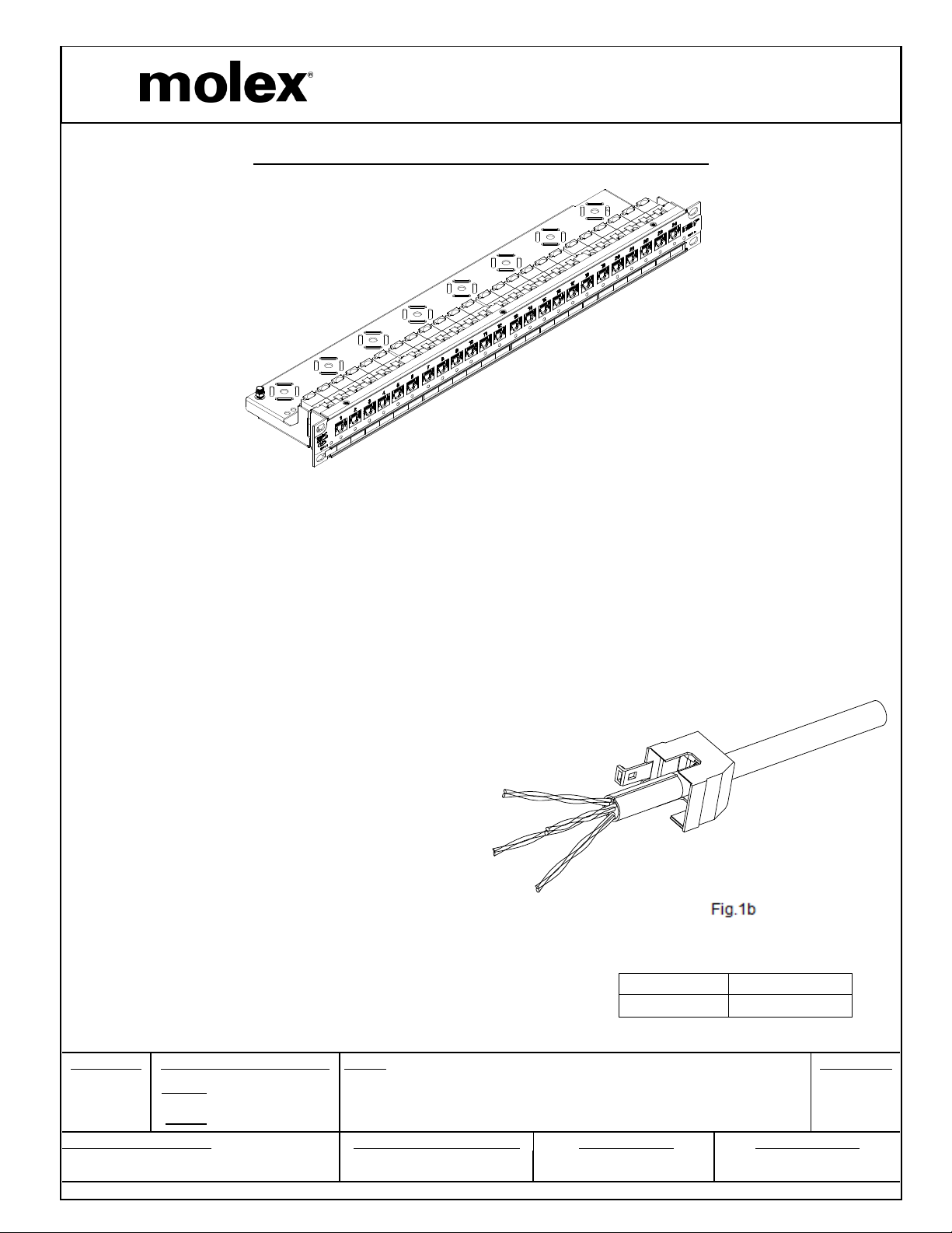
INSTALLATION INSTRUCTIONS: PID-00231 PANEL
PARTS LIST
Panel with Integrated Cable Manager
Hardware Kit
Rear Housing Assembly
Stuffer Caps
Labels
Instruction Sheet
GENERAL REQUIREMENTS
The following tools are required for installation of
the panel:
110 termination tool set on low impact
Flush cut pliers
Cable stripping tool
Phillips screwdriver
ASSEMBLY INSTRUCTIONS
1. Panel Preparation
1a. Remove cable management tray from panel.
1b. For each cable, slide rear housing on cable
in the proper direction.
MPN NO. SAP NO.
215-390 187000372
REVISION: ECR/ECN INFORMATION: TITLE:
EC No:
A
DOCUMENT NUMBER: CREATED / REVISED BY: CHECKED BY: APPROVED BY:
DATE:
MTS2012-0032
2013 / 01 / 21
Installation Instructions PID-00231
MIIM Category 6A Patch Panel
BJ Mahendra CG Raghavan Samuel Huber
TEMPLATE FILENAME: APPLICATION_SPEC[SIZE_A](V.1).DOC
SHEET No.
1
of 4
Page 2
AS-18700
-
059
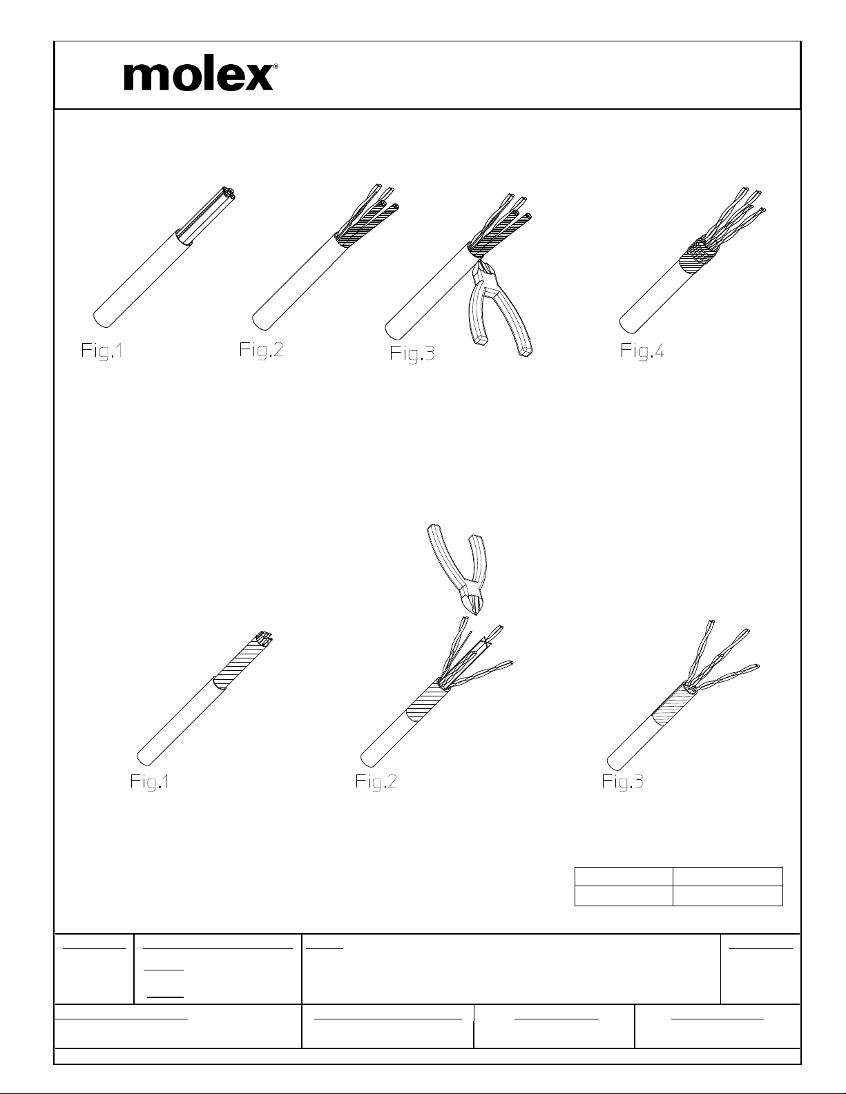
2.Cable Preparation
2a. U/FTP
APPLICATION SPECIFICATION
1) Strip the cable a minimum of 40mm.(Fig. 1)
2) Remove foil from three pairs and untwist pairs. (Fig. 2)
3)Use clippers to cut-off foil. (Fig. 3)
4) Pull the foil shield back from the forth pair over the jacket. Ensure the cable foil’s conductive surface is
facing out. Wrap the drain wire around the foil shield. (Fig. 4)
2b. F/UTP
1) Strip the cable a minimum of 40mm. (Fig. 1)
2) Untwist pairs and remove cable separator with wire clippers. (Fig. 2)
3) Pull the foil shield back over the jacket. Ensure the cable foil’s conductive surface is facing out.Wrap
thedrain wire around the foil shield. (Fig. 3)
MPN NO. SAP NO.
215-390 187000372
REVISION: ECR/ECN INFORMATION: TITLE:
EC No:
A
DOCUMENT NUMBER: CREATED / REVISED BY: CHECKED BY: APPROVED BY:
DATE:
MTS2012-0032
2013 / 01 / 21
Installation Instructions PID-00231
MIIM Category 6A Patch Panel
BJ Mahendra CG Raghavan Samuel Huber
TEMPLATE FILENAME: APPLICATION_SPEC[SIZE_A](V.1).DOC
SHEET No.
2
of 4
Page 3

APPLICATION SPECIFICATION
AS-18700
-
059
3. Cable Termination
3a. Untwist wires and position for
terminating.
3b. Position cable to align each pair with
corresponding color code. Ensure cable
sheath is maintained up to the jack.
3c. Punch down with110 tool.
4. Stuffer Cap
Install stuffer cap.
3
c
.
Fig.4
Fig. 3a.
Fig. 3b.
Fig. 3c
5. Fitting Rear Housing
Attach housing and close cable clamp.
Clamp must contact drain wire wrapped
around the cable.
Fig.5
MPN NO. SAP NO.
215-390 187000372
REVISION: ECR/ECN INFORMATION: TITLE:
EC No:
A
DOCUMENT NUMBER: CREATED / REVISED BY: CHECKED BY: APPROVED BY:
DATE:
MTS2012-0032
2013 / 01 / 21
Installation Instructions PID-00231
MIIM Category 6A Patch Panel
BJ Mahendra CG Raghavan Samuel Huber
TEMPLATE FILENAME: APPLICATION_SPEC[SIZE_A](V.1).DOC
SHEET No.
3
of 4
Page 4

APPLICATION SPECIFICATION
AS-18700
-
059
6. Cable Dressing
6a. Install cable management tray to panel.
6b. Press cables neatly on cable
management tray and secure with cable
ties or Velcro strips ensuring 29 mm
bend radius is maintained.
6c. Individually earth each panel to cabinet
earth position.
Fig.6
8. RemovalInstructions
To remove rear housing, open clamp and
pull up on latch on top of the housing.
Note: Use flat screwdriver to
Lift latch of housing.
7. Attach MIIM I/O cable to I/O port
Secure to cable management tray if desired.
Fig.7
9. Adding MIIM panels to the MIIM System
Connect a patch cord between the RJ45 port
on the back of the panel to a port on a MIIM
scanner.
Refer to the scanner and panel firmware
update section in the MIIM Installation Guide
to insure the panel firmware and scanner
application are matched correctly.
Access the scanner to confirm scanner
application and panel firmware versions.
If necessary, perform a panel firmware
update on the panel.
Fig.8
MPN NO. SAP NO.
215-390 187000372
REVISION: ECR/ECN INFORMATION: TITLE:
EC No:
A
DOCUMENT NUMBER: CREATED / REVISED BY: CHECKED BY: APPROVED BY:
DATE:
MTS2012-0032
2013 / 01 / 21
Installation Instructions PID-00231
MIIM Category 6A Patch Panel
BJ Mahendra CG Raghavan Samuel Huber
TEMPLATE FILENAME: APPLICATION_SPEC[SIZE_A](V.1).DOC
SHEET No.
4
of 4
 Loading...