

Page 1

ENGINEERING RECORD
NO : 625923
SAP NO: 187000536
Doc No: 187000536 Doc part: AS
REV- A
http://www.molexces.com/
DATE: 2019/Oct/18
MPN/FMT-042 (2019/FEB/15 REV-02).
THIS INFORMATION IS CORRECT AS AT THE TIME OF PUBLICATION, SPECIFICATION ARE SUBJECT TO CHANGE SHEET No. 1 of 3
INSTALLATION INSTRUCTIONS
BEFORE INSTALLING OR ADJUSTING THIS PRODUCT,
PLEASE READ THESE INSTRUCTIONS CAREFULLY.
PLEASE KEEP THIS GUIDE FOR FUTURE REFERENCE
IP67 C6A Jack and IP67 Face Plate
1.0 Scope
This document will describe the installation instructions for IP67 C6A Jack and IP67 Face Plate
2.0 Procedure
Tools required: 110 punch down tool, cable jacket stripper tool, cable clippers and wire clippers
1. Strip of 1.2”/ 30mm of jacket from the cable with the cable jacket stripper (Fig 1.)
2. U/FTP cable preparation
a. Unwrap and remove 3 of the twisted pair’s foils with wire clippers
b. Wrap the remaining 1.2”/30mm foil off the 4
th
pair down the length of the cable jacket (ensure that the
conductive surface of the foil is facing out)
c. Wrap the drain wire around the foil and the cable sheath
3. F/UTP cable preparation
a. Unwrap the overall foil from the cable
b. Remove the cellophane wrap from the cable
c. Cut the central spline with wire clippers
d. Wrap 1.2”/30mm of foil down the length of the cable jacket (ensure that the conductive surface of the
foil is facing out)
e. Wrap the drain wire around the foil and cable sheath
Fig. 1
Page 2
ER NO : 625923
SAP NO: 187000536
Doc No: 187000536 Doc part: AS
REV-A
MPN/FMT-042 (2019/FEB/15 REV-02). SHEET No. 2 of 3
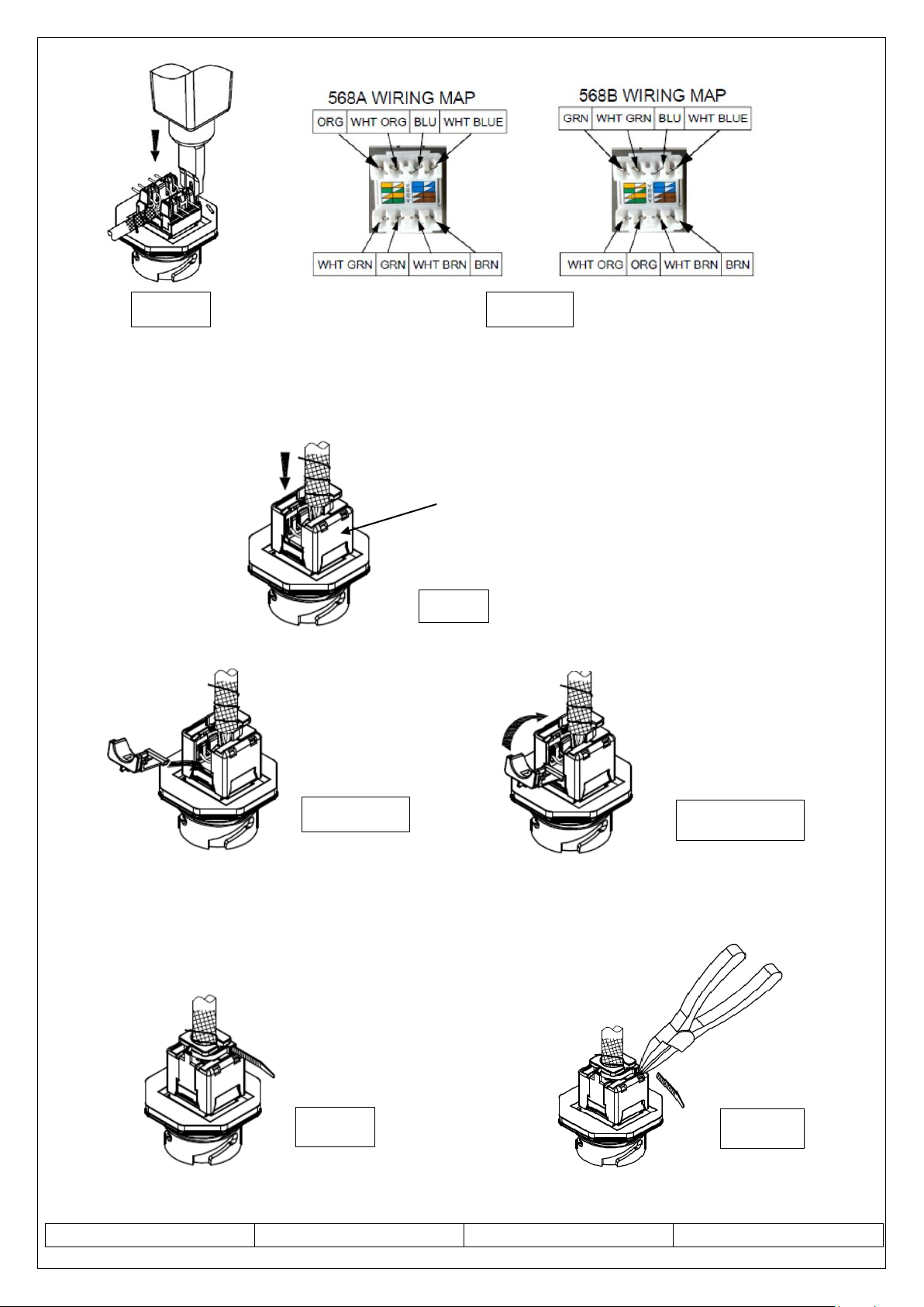
4. Terminate the cable to the jack following the wiring map color coding shown above.
a. Terminate each pair into the corresponding IDT contacts using the 110 punch down tool (Fig 2 & 3).
Keep the pairs twisted as close as possible to the IDT towers allowing a maximum of 6mm untwist.
b. Ensure the wires are trimmed flush to the IDT towers
5. Place the shielded cap on the jack and press down to ensure that it is fully seated. (Fig.4)
6. Insert the hinged side-cover into the slot in the cap. (Fig.5) then snap the side-over shut.
7. Ensure that the foil and drain wire on the cable is in contact with the shielded collar of the jack shielded cap.
(Fig. 6)
8. Fit the cable tie to the shielded collar. (Fig.7)
9. Cut the excess cable tie wrap off as close to the shielded collar as possible. (Fig.8)
Fig.2
Fig. 3
Fig. 4
Fig 5.
Fig.6
Fig. 7
Fig. 8
Shielded cap
Page 3

ER NO : 625923
SAP NO: 187000536
Doc No: 187000536 Doc part: AS
REV-A
MPN/FMT-042 (2019/FEB/15 REV-02). SHEET No. 3 of 3
Fitting the C6A IP67 Jack to the IP67 Face Plate
Step 1: Place the industrial connector into the faceplate Step 2: Use the large Nut to fix the connector to the
From the back side of the plate Stainless steel plate
Step 3: Follow the direction of the nut and screw. Step 4: Mount the Cover/Seal between
the large nut and the faceplate
Step 5: Secure the wall plate to the backbox in its correct orientation with the supplied screws.
Insert an industrial Patch Cord into the industrial connector to connect to a network.
(If not installing a plug, please place the seal cover on the outlet to protect it.)
*For JACK C6A IP67 SHIELDED to be fitted into Back box, refer the above steps as shown for Face plate.
 Loading...