

Page 1

Impact™ Backplane and Daughtercard Tooling
IMPACT™ Backplane and DaughterCard
Installation and Repair Tooling
Operation Manual
Order No. 62201-8799
Description
Operation
Maintenance
Doc. No: TM-622018799 Release Date: 08-31-09 UNCONTROLLED COPY Page 1 of 35
Revision: G Revision Date: 06-16-14
Page 2

Impact™ Backplane and Daughtercard Tooling
Read and understand all of the instructions and safety information in this
manual before operating or servicing this tool.
Keep this manual available when using this tool.
Replacement manuals are available for download at no charge at
www.molex.com.
SAFETY ALERT SYMBOL
This symbol is used to call your attention to hazards or unsafe practices which could result in an injury or property
damage. The signal word, defined below, indicates the severity of the hazard. The message after the signal word
provides information for preventing or avoiding the hazard.
DANGER
DANGER:
Indicates an imminently hazardous situation which, if not avoided, could result in death or serious injury.
WARNING
WARNING:
Indicates a potentially hazardous situation which, if not avoided, could result in death or serious injury.
CAUTION
CAUTION:
Indicates a potentially hazardous situation which, if not avoided, may result in minor or moderate injury.
CAUTION may also be used to alert against unsafe practices associated with events that could lead
to personal injury.
WARNING
WARNING
Always wear proper eye protection when
Operating or servicing these tools.
Failure to wear eye protection could result
in serious eye injury from flying debris.
Never use a press without guards or
safety devices that are intended to prevent
hands from remaining in the die space.
Failure to observe this warning could result
in severe injury or death.
WARNING
WARNING
Never wear clothing or jewelery that is loose or
That Could potentially hang into the equipement
And get caught.
Failure to observe this warning could result in
Severe Injury or death.
Never install or service these tool while
connected to any electrical power source.
Disconnect power by unplugging the press
from its power source.
Failure to observe this warning could result
In severe injury or death.
WARNING
WARNING
Never operate, service, install, or adjust this
Machine without proper instruction and without
first reading and understanding the instructions
in this manual and all applicable press and/or
wire processing machine
manuals.
Use extreme caution when using compressed
air to clean the equipment.
The forces created by compressed air can force
debris into the tool.
Failure to observe these precautions may
result in injury or property damage.
Safety Warnings and Information
Doc. No: TM-622018799 Release Date: 08-31-09 UNCONTROLLED COPY Page 2 of 35
Revision: G Revision Date: 06-16-14
Page 3

Impact™ Backplane and Daughtercard Tooling
CAUTION
Never perform any service or maintenance other than as described in this manual.
Never modify, alter or misuse the equipment
Failure to observe this precaution may result in injury and property damage.
Tooling Technical Assistance
Molex offers tooling technical assistance for customers who may need some guidance for tooling adjustments. This support
can be obtained by calling either of the two numbers listed below and asking for the Molex Tooling Group.
Call Toll Free 1-800-786-6539 (US) 1-630-969-4550 (Global).
This assistance is limited to the operation and set-up of a customer’s Molex Tools tool. Questions with regard to Molex
connector products or how to identify the proper tooling and/ or tooling documentation should be directed to your local Molex
personnel or Customer Service Representative.
When calling for service on these tools it is recommended to have the following: a copy of the Operation Manual, the
Specific Application Specification Sheet and a person familiar with the tools should be present. The following information is
also recommended to supply:
1. Customer name
2. Customer address
3. Person to contact such as (name, title, e-mail, and telephone number)
4. Tools order number (Lease number also if applicable)
5. Serial number (Lease number also if applicable)
6. Molex Connector product order number
7. Urgency of request
8. Nature of problem
Molex Application Tooling Group
2200 Wellington Court
Lisle, IL 60532, USA
Tel: +1 (630) 969-4550
Fax:+1 (630) 505-0049
Visit our Web site at http://www.molex.com
Doc. No: TM-622018799 Release Date: 08-31-09 UNCONTROLLED COPY Page 3 of 35
Revision: G Revision Date: 06-16-14
Page 4

Impact™ Backplane and Daughtercard Tooling
Table of Contents
IMPACT™ Backplane and DaughterCard ............................................................................................................................................... 1
Order No. 62201-8799 ............................................................................................................................................................................. 1
Safety Warnings and Information ............................................................................................................................................................ 2
Table of Contents .................................................................................................................................................................................... 4
Section 1 .................................................................................................................................................................................................. 5
General Description ............................................................................................................................................................................. 6
1.1 Description ............................................................................................................................................................................. 6
1.2 Features ................................................................................................................................................................................. 6
1.3 Technical Specifications ......................................................................................................................................................... 6
1.4 Delivery Check ....................................................................................................................................................................... 6
1.5 Tools ...................................................................................................................................................................................... 6
1.6 Press Requirements ............................................................................................................................................................... 6
Section 2 .................................................................................................................................................................................................. 7
Installation and Operation ................................................................................................................................................................... 7
2.1 Printed Circuit Board Support ................................................................................................................................................ 8
2.2 Press Stroke Adjustment ........................................................................................................................................................ 8
2.3 Installation .............................................................................................................................................................................. 8
2.4 Operation ............................................................................................................................................................................... 9
Section 3 ................................................................................................................................................................................................ 13
Maintenance ...................................................................................................................................................................................... 13
3.1. Cleaning ............................................................................................................................................................................... 14
3.2 Lubrication............................................................................................................................................................................ 14
3.3 Troubleshooting ................................................................................................................................................................... 14
Section 4 ................................................................................................................................................................................................ 15
Available Tools .................................................................................................................................................................................. 15
4.1 Standard Press-In-Tools ...................................................................................................................................................... 16
Table 4-1....................................................................................................................................................................................... 16
Table 4-2....................................................................................................................................................................................... 25
Table 4-3....................................................................................................................................................................................... 25
4.2 Standard Tool Ordering Procedure ...................................................................................................................................... 29
Section 5 ................................................................................................................................................................................................ 30
5.1 Impact™ Backplane Repair Procedure: ............................................................................................................................... 31
5.2 Glossary of Terms: ............................................................................................................................................................... 35
Doc. No: TM-622018799 Release Date: 08-31-09 UNCONTROLLED COPY Page 4 of 35
Revision: G Revision Date: 06-16-14
Page 5

Impact™ Backplane and Daughtercard Tooling
Section 1
Press Requirements for Impact™ Connectors
1.1 Description
1.2 Features
1.3 Technical Specifications
1.4 Delivery Check
1.5 Tools
1.6 Press Requirements
Doc. No: TM-622018799 Release Date: 08-31-09 UNCONTROLLED COPY Page 5 of 35
Revision: G Revision Date: 06-16-14
Page 6

Impact™ Backplane and Daughtercard Tooling
General Description
1.1 Description
This manual covers the tooling available to press Molex
Impact™ Backplane Power Modules, Backplane
Connectors, Daughtercard and Coplanar Modules into
printed circuit boards. Repair tools and custom tools are
also covered. All insertion tooling is designed to go into
a flat platen press.
1.2 Features
The press-in tooling is designed so that one module will
press in one connector, or several modules can be
mounted in a tool holder and be used to press in any
combination of connectors in one operation. See Section
4-2 (Ordering Instructions) for details.
1.3 Technical Specifications
Dimensions and Weight
The dimensions and weight depend on the size of the
tooling used.
1.4 Delivery Check
Carefully remove the tooling from its shipping container
and check to be sure what was received matches the
purchase order and no damage has occurred.
1.5 Tools
A metric hex wrench set will be required to assemble or
disassemble tooling mounted in the optional tooling
holder.
Molex Presses
Molex does not offer a press that is suitable for this
application. The customer is encouraged to use one
of the many industry-standard presses to install the
Impact™ connectors.
1.6 Press Requirements
All Impact™ insertion tools are designed to fit in a flat platen
(or flat rock) press.
The press must have sufficient working area to accept the
size of the printed circuit board.
The press frame and base must withstand the insertion force
requirements for the Impact™ products.
Insertion Force Requirements
Backplane assemblies: 2.7kgf (6 lb.) per pin
Daughtercard assemblies: 1.8kgf (4 lb.) per pin
Power module assemblies: 6kgf (13.2 lb.) per pin
Press Operation Characteristics
The capability to detect force variations as low as 4.5kg
(10 lb.) during the press-in cycle; excessive force
measurement should stop the press-in cycle.
The rate of pressing can be regulated as low as
0.13mm (0.005 in) per second.
Press stroke control to within ±0.25mm (0.010 in.).
Total press stroke must be at least 19mm (0.75 in.).
Doc. No: TM-622018799 Release Date: 08-31-09 UNCONTROLLED COPY Page 6 of 35
Revision: G Revision Date: 06-16-14
Page 7

Impact™ Backplane and Daughtercard Tooling
Installation and Operation
2.1 Printed Circuit Board Support
2.2 Press Stroke Adjustment
2.3 Installation
2.4 Operation
Section 2
Doc. No: TM-622018799 Release Date: 08-31-09 UNCONTROLLED COPY Page 7 of 35
Revision: G Revision Date: 06-16-14
Page 8
Impact™ Backplane and Daughtercard Tooling
Figure 2-2
TOOLING HOLDER
M3 SET
SCREWS
KEYWAY
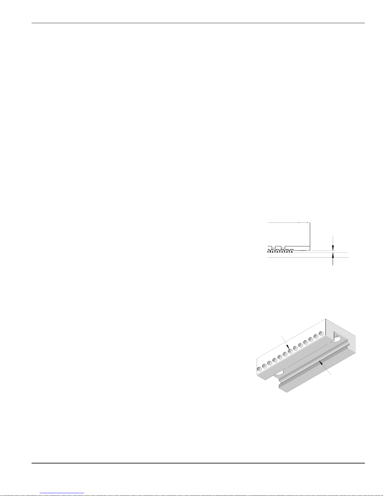
Figure 2-1
MAXIMUM CLEARANCE WHEN
CONNECTOR FULLY SEATED
0.10mm
(.004 in.)
Maximum
Installation and Operation
2.1 Printed Circuit Board Support
Due to the high forces required to press in compliant-pin connectors, a backup or support plate is suggested to prevent
damage to the printed circuit board. The support fixture should have clearance for the connector terminals if they
protrude through the underside of the printed circuit board. The support fixture should have some method of locating the
PCB consistently. Due to the custom nature of each application, Molex does not supply support and locating fixtures.
The customer normally fabricates the fixture to fit their application.
The following is one way of making a printed circuit board support and locating fixture:
1. Locate a suitable piece of material for the backup. It should be approximately 20mm thick and the same size or slightly
larger than the printed circuit board to be used. While aluminum could be used, a rigid nonconductive material such as a
phenolic is preferred. (A stack of scrap printed circuit boards of suitable size can also be fastened together.)
2. Obtain a scrap printed circuit board like the ones to be assembled. Attach this board to the material from step 1.
3. Using an oversize drill bit, drill through each hole where a pin from the connector will go. Drill deep enough into the
lower material to be certain the pins do not bottom out when inserted (at least 5.0mm (0.20”) deep).
4. Locate two (2) holes on the printed circuit board to use as locating points. Mount suitably sized dowel pins in these two
locations on the support fixture.
5. Clear out the support for any components mounted on the underside of the printed circuit board.
6 Place a printed circuit board on top of the support, located by the two pins, and check that the holes for the connector
pins are aligned.
7. By hand, pre-insert a connector in the printed circuit board.
8. Load the insertion tool into the connector.
9. Place the support with the printed circuit board under the press ram.
10. Press the connector into the printed circuit board and observe for any
deflection of the board when the ram is at the bottom of its stroke.
2.2 Press Stroke Adjustment
Most presses have some means of adjusting the stroke; please refer to the press
manual for press stroke adjustments. The stroke should be adjusted so that when the press ram stops in the down position,
the bottom of the connector is flush to 0.10mm (.004”) above the surface of the printed circuit board. See Figure 2-1.
2.3 Installation
To install insertion modules into a tooling holder (see Table 4-2), use the
following procedure:
1. Along the lower edge of the tooling holder is a row of M3 set screws. (See
Figure 2-2) Loosen these a few turns so that they do not protrude into the
inside of the holder.
2. Slide the insertion modules into the tooling holder in the proper order. See
Figure 2-3. The modules are keyed so that they cannot be installed
backwards.
Doc. No: TM-622018799 Release Date: 08-31-09 UNCONTROLLED COPY Page 8 of 35
Revision: G Revision Date: 06-16-14
Page 9

Impact™ Backplane and Daughtercard Tooling
Figure 2-3
MOUNTING INSERT MODULE IN
A MOUNTING BLOCK
TYPICAL INSERTION
MODULES
TOOLING HOLDER
Figure 2-4
TYPICAL INSERTION
TOOL ASSEMBLY
M3 x 8mm LONG
SET SCREWS (3)
EVENLY SPACED
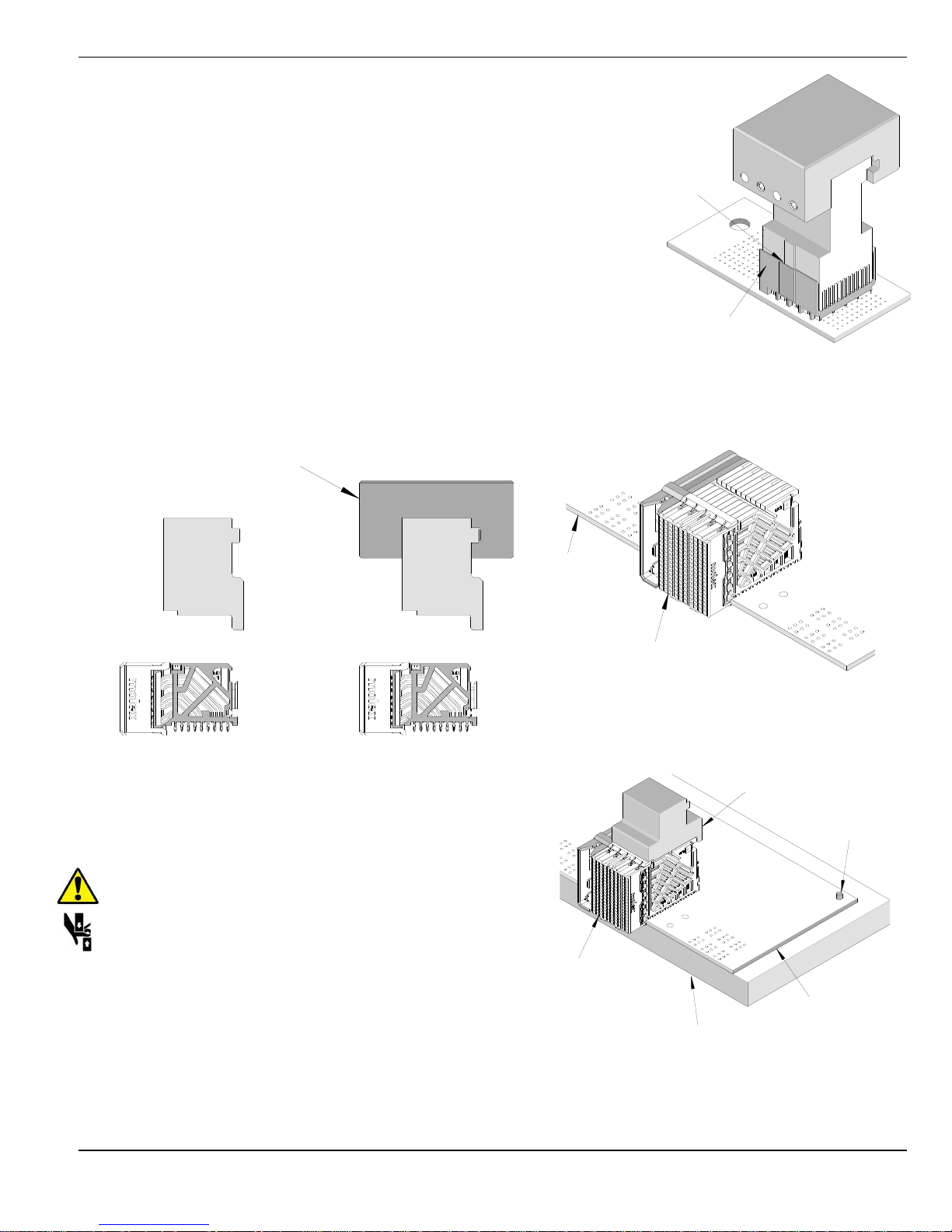
Figure 2-6
CONNECTOR ASSEMBLY
ON PC BOARD SUPPORT PALLET
SUPPORT PALLET
LOCATING PIN
LOCATING PIN
PC BOARD
CONNECTOR
ASSEMBLY
Figure 2-5
ALIGNING TERMINAL PINS TO HOLES
PC BOARD
SIGNAL MODULE
3. Tighten the M3 set screws against the modules with two (2) set screws evenly spaced on a 10mm wide insertion tool and
at least three (3) set screws evenly spaced on a 25mm wide insertion tool. Figure 2-4 shows a typical completed
assembly.
CAUTION: Do not over tighten the setscrews; this could damage the insertion tool.
NOTE: See Section 4 for details on selecting modules and Press-In tools combinations.
2.4 Operation
Backplane Insertion Tooling
1. Carefully pre-insert, by hand, the backplane signal module(s) into the printed circuit board hole pattern. Make sure the
connector(s) are oriented properly by confirming the location of the #1 circuit notch with respect to the printed circuit
board layout. See Figure 2-5.
2. Place the pre-loaded board into the support pallet (Optional). See Figure 2-6.
3. Locate the tooling assembly in the connector assembly, carefully checking alignment. The orientation keys on the tool must
engage with the groove on the connector housing. See Figure 2-7.
4. Position the pre-loaded support pallet under the press ram.
Doc. No: TM-622018799 Release Date: 08-31-09 UNCONTROLLED COPY Page 9 of 35
Revision: G Revision Date: 06-16-14
Page 10
Impact™ Backplane and Daughtercard Tooling
Figure 2-10
LOCATING PIN
SUPPORT PALLET
CONNECTOR
ASSEMBLY
PC BOARD
PRESS-IN
TOOL
WITH 62201-95XX
RAIL
Figure 2-8
ALONE
Figure 2-9
TYPICAL DAUGHTERCARD
ASSEMBLY ON THE PC BOARD
SIGNAL MODULE
PCB
ORIENTATION
KEY
Figure 2-7
TOOLING LOCATED IN THE
CONNECTOR ASSEMBLY
CONNECTOR
HOUSING
5. Cycle the insertion press.
6. Press the header assembly until there is less than 0.10mm (.004 in)
clearance between the bottom of the plastic housing and the surface of the
printed circuit board.
7. Remove the loaded support pallet.
8. Carefully remove the insertion tool assembly. Remove the printed circuit
board from the pallet.
Daughtercard Insertion Tooling
Operation for inserting daughtercard assemblies is similar to backplanes and
can be used alone or stacked in a tool holder for larger connector assemblies.
See Figure 2-8.
1. Locate the daughtercard connector assembly on the printed circuit board.
2. Pre-insert the assembly into the board by hand. Check for proper seating,
without contact pins bending under the assembly after pre loading on to the
Printed circuit board. See Figure 2-9.
3. Locate the printed circuit board with the connector assembly
on the support pallet.
4. Position the insertion tooling on the connector assembly.
See Figure 2-10.Position the printed circuit board under the
press platen (Optional).
CAUTION: To prevent injury, never operate any press
without the guards in place. Refer to the press
manufacturer’s instruction manual.
5. Press the daughtercard module until there is less than
0.10mm (.004 in) clearance between the bottom of the
plastic housing and the surface of the printed circuit board.
6. Remove the loaded support pallet from the press.
7. Remove the insertion tool.
8. Carefully remove the assembled printed circuit board from the support pallet.
Doc. No: TM-622018799 Release Date: 08-31-09 UNCONTROLLED COPY Page 10 of 35
Revision: G Revision Date: 06-16-14
Page 11
Impact™ Backplane and Daughtercard Tooling
WITH
62201-95XX
RAIL
Figure 2-11
ALONE
PRESS-IN
TOOL
POWER
HEADER
PRESS-IN
TOOL
POWER
HEADER
GUIDE
SURFACE
GUIDE
SURFACE
Figure 2-12
TOOLING
HOLDER
M3 SET
SCREW
VERTICAL
POWER
MODULE
PC BOARD
VERTICAL
PRESS-IN
TOOL
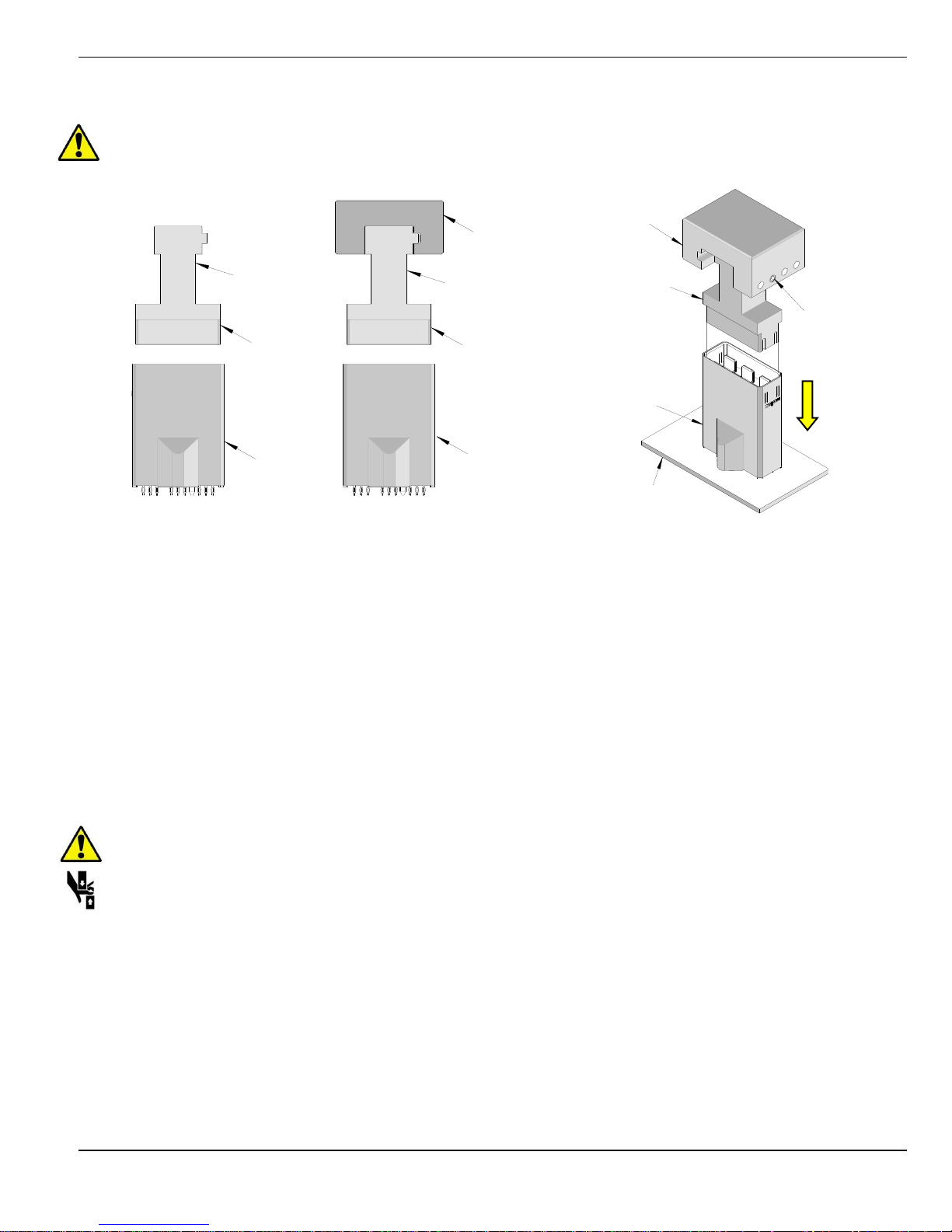
Vertical Power Module Press-In Tooling
CAUTION: Vertical Power Module must be installed separately without any backplane or daughtercard
assemblies in the combinations.
Depending on the number of modules to be installed and/or the press used, this tool can be used as a stand-alone or with a
group of press-in tools, mounted in a 62201-95XX holder (ordered separately). See Figure 2-11.
1. If the tooling holder is being used, slide the insertion modules into the tooling holder in the proper order. The modules are
keyed so that they cannot be installed backwards.
2. Now tighten the M3 set screws against the modules using the following setups:
One (1) set screw against modules under 10mm wide
Two (2) set screws evenly spaced on a 10mm wide power module.
At least three (3) set screws evenly spaced on a 25mm wide power module.
3. Carefully pre-insert, by hand, the vertical power module(s) into the printed circuit board hole pattern. See Figure 2-12.
Make sure the module(s) are oriented properly to the printed circuit board layout.
4. Line-up the Press-In tool so that the guide surfaces on the tool are in line with the sides of the vertical power module.
See Figure 2-11.
5. Using the application tool and an appropriate press, seat the vertical power module until there is less than 0.10mm
(.004 in) clearance between the bottom of the plastic housing and the surface of the printed circuit board.
CAUTION: To prevent injury, never operate any press without the guards in place. Refer to the press
manufacturer’s instruction manual.
Right Angle Power Module Press-In Tooling
Depending on the number of connectors to be installed and/or the press used, this tool can be used alone or with a group of
press-in tools, mounted in a 62201-95XX holder (ordered separately). See Figure 2-13 and 2-14.
1. If the tooling holder is being used, slide the Press-In Tools into the tooling holder in the proper order. The Press-In Tools
are keyed so that they cannot be installed backwards.
2. Tighten the M3 set screws against the Press-In Tool using the following setups:
One (1) set screw is used against the Press-In Tool under 10mm guide module.
Two (2) set screws evenly spaced on a 10mm wide Press-In Tool.
At least three (3) set screws evenly spaced on a 25mm wide Press-In Tool.
Doc. No: TM-622018799 Release Date: 08-31-09 UNCONTROLLED COPY Page 11 of 35
Revision: G Revision Date: 06-16-14
Page 12

Impact™ Backplane and Daughtercard Tooling
Figure 2-15
0.10mm (0.004”)
Maximum
Figure 2-14
Right angle power module is seated along side the
Daughtercard signal module.
For ganged power modules, additional power
module press-in-tools may be needed;
see sales drawings for ganged product dimensions.
PCB REF
RIGHT ANGLE POWER MODULE and
DAUGHTERCARD PRESS-IN TOOL REF
TOOLING HOLDER
62201-95XX
RIGHT ANGLE
POWER MODULE
DAUGHTERCARD
Figure 2-13
STAND-ALONE
DAUGHTERCARD
PRESS-IN TOOL REF
PCB REF
RIGHT ANGLE
POWER MODULE REF
RIGHT ANGLE POWER
MODULE PRESS-IN TOOL
DAUGHTERCARD
3. Carefully insert, by hand, the power module(s) into the printed circuit board hole pattern.
4. Place the application tool on top of the power module with the back guide surface of the tool against the back of the
power module. See Figure 2-14.
5. Using the application tool and an appropriate press, seat the power module until there is less than 0.10mm (.004 in)
clearance between the bottom of the plastic housing and the surface of the printed circuit board. See Figure 2-15.
CAUTION: To prevent injury, never operate any press without the guards in place. Refer to the press
manufacturer’s instruction manual.
Doc. No: TM-622018799 Release Date: 08-31-09 UNCONTROLLED COPY Page 12 of 35
Revision: G Revision Date: 06-16-14
Page 13

Impact™ Backplane and Daughtercard Tooling
3.1 Cleaning
3.2 Lubrication
3.3 Troubleshooting
Section 3
Maintenance
Doc. No: TM-622018799 Release Date: 08-31-09 UNCONTROLLED COPY Page 13 of 35
Revision: G Revision Date: 06-16-14
Page 14

Impact™ Backplane and Daughtercard Tooling
Symptom
Cause
Solution
Connector
damage
Press stroke set too low.
Refer to the appropriate press manual
and adjust the stroke. See Section 2.2
Connector and/or tooling not properly aligned
Check Fixture and Repair as required.
Check alignment of fixture in press
Check to be sure the press platen is
pressing squarely on the tooling block.
Tooling bent or damaged
Replace tool
3.1. Cleaning
Once a day, the support fixture should be cleaned of dust and plating particles and other debris. Compressed air may be
necessary to remove debris from the pin clearance holes.
CAUTION: Use extreme caution when using compressed air for cleaning, it can cause debris to get lodged in
the tooling or come flying out at the operator. USE of proper safety glasses by the operator and onlookers is
required.
3.2 Lubrication
There is no lubrication required on any of the Impact™ tooling. However, presses may have their own requirements for
lubrication and maintenance. The instruction manual for the specific press being used should be referred to.
3.3 Troubleshooting
Doc. No: TM-622018799 Release Date: 08-31-09 UNCONTROLLED COPY Page 14 of 35
Revision: G Revision Date: 06-16-14
Page 15

Impact™ Backplane and Daughtercard Tooling
4.1 Standard Press-In-Tools
Table 4-1 Assembly Tooling for Impact™ Signal and Power Assemblies
Table 4-2 Standard Tool Holders for Molex Press Fit Insertion Tools
Table 4-3 Field Repair Tooling for Impact™ Backplane and Daughtercard Assemblies
4.2 Standard Tool Ordering Procedure
Section 4
Available Tools
Doc. No: TM-622018799 Release Date: 08-31-09 UNCONTROLLED COPY Page 15 of 35
Revision: G Revision Date: 06-16-14
Page 16

Impact™ Backplane and Daughtercard Tooling
Impact™ 100 Ohm Products – Insertion Tools
Pair
Column
Product
Module Type
Series
Tool
Width
Illustration
2
8
100 Ohm Coplanar
RAM
170026
62201-8851
15.1mm
(0.59 In.)
10
100 Ohm Conventional
BP
76453
76455
171290
62201-8692
18.8mm
(0.74 In.)
100 Ohm Coplanar
RAM
76450
62201-8778
18.8mm
(0.74 In.)
100 Ohm Conventional
DC
76460
100 Ohm Coplanar
RAM
170026
12
100 Ohm
RAM
76450
62201-8979
22.7mm
(0.89 In.)
16
100 Ohm Conventional
BP
76453
76455
171290
62201-8694
30.22mm
(1.19 In.)
100 Ohm Conventional
DC
76460
62201-8779
30.22m
(1.19 In.)
100 Ohm Coplanar
RAM
76450
62201-8779
30.22m
(1.19 In.)
100 Ohm Conventional
DC
76460
100 Ohm Custom
RAM
170026
18
100 Ohm Custom
RAM
170026
62201-8852
34.0mm
(1.34 In.)
3
6
100 Ohm Conventional
BP
76162
76165
171292
62201-8781
11.2mm
(0.44 In.)
100 Ohm Orthogonal
BP
76855
76856
171344
171345
62203-0460
12.0mm
(0.47 In.)
100 Ohm Conventional
DC
76170
62201-8780
11.2mm
(0.44 In.)
100 Ohm Mezzanine
Mezzanine
170415
62201-8859
11.4mm
(0.45 In.)
4.1 Standard Press-In-Tools
Standard Insertion Tools
All the applicable Impact™ connectors and the standard tooling required for each connector are located in these tables.
TABLE 4-1
Assembly Tooling (For use in standard tool holder)
Refer to the individual instruction sheets for more information on Individual tools.
Doc. No: TM-622018799 Release Date: 08-31-09 UNCONTROLLED COPY Page 16 of 35
Revision: G Revision Date: 06-16-14
Page 17

Impact™ Backplane and Daughtercard Tooling
Impact™ 100 Ohm Products – Insertion Tools
Pair
Column
Product
Module Type
Series
Tool
Width
Illustration
100 Ohm Orthogonal
DC
76860
62201-8744
11.80mm
(0.46 In.)
3 6 100 Ohm Ortho Direct
RAM
171573
62203-0026
15.0mm
(0.59 In.)
3
8
100 Ohm Orthogonal
BP
76855
76856
171344
62203-0465
12.0mm
(0.47 In.)
100 Ohm Conventional
BP
76162
76165
171292
62201-8674
15.0mm
(0.59 In.)
100 Ohm Conventional
DC
76170
62201-8675
15.0mm
(0.59 In.)
100 Ohm Coplanar
RAM
76410
100 Ohm Mezzanine
Mezzanine
170415
62201-8858
15.2mm
(0.60 In.)
100 Ohm Orthogonal
DC
76860
62201-8746
15.85mm
(0.62 In.)
3
10
100 Ohm Conventional
BP
76162
76165
171292
62201-8647
18.8mm
(0.74 In.)
100 Ohm Conventional
DC
76170
62201-8646
18.9mm
(0.74 In.)
100 Ohm Coplanar
RAM
76410
100 Ohm Mezzanine
Mezzanine
170415
62201-8857
19.0mm
(0.75 In.)
3
14
Impact XTR
DC
171180
62201-8868
13.8mm
(0.54 In.)
100 Ohm Conventional
BP
76162
62201-8853
26.45mm
(1.04 In.)
3
16
100 Ohm Conventional
BP
76162
171292
62201-8651
30.25mm
(1.19 In.)
100 Ohm Mezzanine
Mezzanine
170415
62201-8856
30.4mm
(1.20 In.)
100 Ohm Conventional
DC
76170
62201-8650
30.3mm
(1.19 In.)
100 Ohm Coplanar
RAM
76410
100 Ohm Coplanar
RAM
170027
4 6 100 Ohm Orthogonal
BP
76845
171348
62203-0470
12.0mm
(0.47 In.)
Doc. No: TM-622018799 Release Date: 08-31-09 UNCONTROLLED COPY Page 17 of 35
Revision: G Revision Date: 06-16-14
Page 18

Impact™ Backplane and Daughtercard Tooling
Impact™ 100 Ohm Products – Insertion Tools
Pair
Column
Product
Module Type
Series
Tool
Width
Illustration
4 6 100 Ohm Conventional
BP
76152
76155
171294
62201-8679
11.2mm
(0.44 In.)
4 6 100 Ohm Conventional
DC
76160
62201-8748
11.75mm
(0.46 In.)
4 6 100 Ohm Orthogonal
DC
76850
4
8
100 Ohm Orthogonal
BP
76845
76846
171348
62203-0575
16.9mm
(0.67 In.)
100 Ohm Conventional
BP
76152
76155
171294
171295
62201-8676
15.0mm
(0.59 In.)
100 Ohm Conventional
BP
76152
62201-8793
15.0mm
(0.59 In.)
100 Ohm Orthogonal
Routable
BP
76849
62201-8678
15.0mm
(0.59 In.)
100 Ohm Conventional
DC
76160
62201-8677
15.0mm
(0.59 In.)
100 Ohm Coplanar
RAM
76500
100 Ohm Orthogonal
DC
76850
100 Ohm Ortho Direct
RAM
76730
171574
62203-0027
20.0mm
(0.79 In.)
4
10
100 Ohm Orthogonal
BP
76845
171348
62203-0475
16.05mm
(0.63 In.)
100 Ohm Conventional
BP
76152
76155
171294
62201-8640
18.4mm
(0.72 In.)
100 Ohm Conventional
DC
76160
62201-8641
18.9mm
(0.74 In.)
100 Ohm Coplanar
RAM
76500
100 Ohm Orthogonal
DC
76850
4
16
100 Ohm Conventional
BP
76152
76155
171294
62201-8644
30.25mm
(1.19 In.)
100 Ohm Conventional
DC
76160
62201-8645
30.25mm
(1.19 In.)
100 Ohm Coplanar
RAM
76500
5
8
100 Ohm Orthogonal
BP
76985
171352
62203-0480
16.05mm
(0.63 In.)
100 Ohm Orthogonal
DC
76990
62201-8754
18.8mm
(0.74 In.)
Doc. No: TM-622018799 Release Date: 08-31-09 UNCONTROLLED COPY Page 18 of 35
Revision: G Revision Date: 06-16-14
Page 19

Impact™ Backplane and Daughtercard Tooling
Impact™ 100 Ohm Products – Insertion Tools
Pair
Column
Product
Module Type
Series
Tool
Width
Illustration
100 Ohm Conventional
BP
76055
171296
62201-8854
15.1mm
(0.59 In.)
5
10
100 Ohm Orthogonal
BP
76985
171352
62203-0580
20.95mm
(0.82 In.)
5
10
100 Ohm Conventional
BP
76055
76163
171296
62201-8658
18.8mm
(0.74 In.)
100 Ohm Mezzanine
Mezzanine
76530
62201-8695
19.0mm
(0.75 In.)
100 Ohm Conventional
DC
76060
62201-8657
18.9mm
(0.74 In.)
100 Ohm Orthogonal
76990
100 Ohm Ortho Direct
RAM
76725
171575
62203-0028
22.0mm
(0.87 In.)
5
12
100 Ohm Orthogonal
BP
76985
76986
171352
62203-0585
25.0mm
(0.98 In.)
100 Ohm Conventional
BP
76163
76055
171296
62201-8708
22.6mm
(0.89 In.)
100 Ohm Mezzanine
Mezzanine
76530
62201-8860
22.8mm
(0.90 In.)
100 Ohm Conventional
DC
76060
62201-8735
18.8mm
(0.74 In.)
100 Ohm Orthogonal
76990
5
14
100 Ohm Conventional
BP
76055
76163
171296
62201-8783
26.45mm
(1.04 In.)
100 Ohm Conventional
DC
76060
62201-8782
26.45mm
(1.04 In.)
100 Ohm Mezzanine
Mezzanine
76530
62201-8861
26.6mm
(1.05 In.)
5
16
100 Ohm Conventional
BP
76055
76163
171293
171296
171297
62201-8665
30.25mm
(1.19 In.)
5
16
100 Ohm Mezzanine
Mezzanine
76530
62201-8696
30.4mm
(1.20 In.)
Doc. No: TM-622018799 Release Date: 08-31-09 UNCONTROLLED COPY Page 19 of 35
Revision: G Revision Date: 06-16-14
Page 20

Impact™ Backplane and Daughtercard Tooling
Impact™ 100 Ohm Products – Insertion Tools
Pair
Column
Product
Module Type
Series
Tool
Width
Illustration
5
16
100 Ohm Conventional
DC
76060
62201-8659
30.25mm
(1.19 In.)
6
10
100 Ohm Orthogonal
BP
76285
171356
62203-0495
20.95mm
(0.82 In.)
6
10
100 Ohm Conventional
BP
76142
76145
171298
62201-8662
18.8mm
(0.74 In.)
6
10
100 Ohm Conventional
DC
76150
62201-8661
18.8mm
(0.74 In.)
100 Ohm Orthogonal
DC
76290
100 Ohm Coplanar
RAM
76560
6
12
100 Ohm Orthogonal
BP
76285
76286
171356
62203-0485
25.00mm
(0.98 In.)
100 Ohm Orthogonal
DC
76290
62201-8762
23.9mm
(0.94 In.)
100 Ohm Ortho Direct
RAM
76735
171576
62203-0029
26.0mm
(1.02 in.)
6
14
100 Ohm Conventional
BP
76142
76145
171298
62201-8639
26.5mm
(1.04 In.)
100 Ohm Conventional
DC
76150
62201-8698
18.8mm
(0.74 In.)
100 Ohm Coplanar
RAM
76560
6
16
100 Ohm Conventional
BP
76142
62201-8855
30.25mm
(1.19 In.)
100 Ohm Conventional
BP
76145
171298
62201-8664
30.25mm
(1.19 In.)
100 Ohm Conventional
DC
76150
62201-8663
30.25mm
(1.19 In.)
100 Ohm Coplanar
RAM
76560
Doc. No: TM-622018799 Release Date: 08-31-09 UNCONTROLLED COPY Page 20 of 35
Revision: G Revision Date: 06-16-14
Page 21

Impact™ Backplane and Daughtercard Tooling
Impact™ 85 Ohm Plus Products – Insertion Tools
Pair
Column
Product
Module Type
Series
Tool
Width
Illustration
2 8 85 Ohm Plus Conventional
BP
171065
62201-8841
15.05mm
(0.59 In.)
2
10
85 Ohm Plus Conventional
BP
171065
62201-8844
18.8mm
(0.74 In.)
85 Ohm Plus Conventional
DC
76460
62201-8778
18.9mm
(0.74 In.)
2
16
85 Ohm Plus Conventional
DC
76460
62201-8779
30.3mm
(1.19 In.)
2
16
85 Ohm Plus Conventional
BP
171065
62201-8847
30.3mm
(1.19 in.)
3
8
85 Ohm Plus Conventional
BP
170513
170522
170525
62201-8801
15.0mm
(0.59 In.)
85 Ohm Plus Conventional
DC
170530
62201-8675
15.0mm
(0.59 In.)
3
10
85 Ohm Plus Conventional
BP
170513
170522
170525
62201-8813
18.9mm
(0.74 In.)
85 Ohm Plus Conventional
DC
170530
62201-8646
18.9mm
(0.74 In.)
3
16
85 Ohm Plus Conventional
BP
170513
170522
170525
62201-8816
30.25m
(1.19 In.)
85 Ohm Plus Conventional
DC
170530
62201-8650
30.3mm
(1.19 In.)
4 6 85 Ohm Plus Conventional
BP
170335
62201-8869
15.0mm
(0.59 In.)
4
8
85 Ohm Plus Conventional
BP
170335
170515
62201-8787
15.0mm
(0.59 In.)
85 Ohm Plus Conventional
DC
170340
62201-8677
15.0mm
(0.59 In.)
85 Ohm Plus Mezzanine
Mezzanine
170390
62201-8863
15.2mm
(0.60 In.)
4
10
85 Ohm Plus Mezzanine
Mezzanine
170390
62201-8717
19.0mm
(0.75 In.)
Doc. No: TM-622018799 Release Date: 08-31-09 UNCONTROLLED COPY Page 21 of 35
Revision: G Revision Date: 06-16-14
Page 22

Impact™ Backplane and Daughtercard Tooling
Impact™ 85 Ohm Plus Products – Insertion Tools
Pair
Column
Product
Module Type
Series
Tool
Width
Illustration
4
10
85 Ohm Plus Conventional
BP
170332
170335
170515
62201-8790
18.8mm
(0.74 In.)
4
10
85 Ohm Plus Conventional
DC
170340
62201-8641
18.9mm
(0.74 In.)
4
12
85 Ohm Plus Mezzanine
Mezzanine
170390
62201-8864
22.8mm
(0.9 In.)
4
12
85 Ohm Plus Conventional
BP
170335
170515
62201-8833
22.7mm
(0.89 In.)
4
12
85 Ohm Plus Conventional
DC
170340
62201-8839
22.7mm
(0.89 In.)
4
14
85 Ohm Plus Mezzanine
Mezzanine
170390
62201-8865
26.6mm
(1.05 In.)
85 Ohm Plus Conventional
BP
170335
170515
62201-8836
26.5mm
(1.04 In.)
85 Ohm Plus Conventional
DC
170340
62201-8840
26.46mm
(1.04 In.)
4
16
85 Ohm Plus Mezzanine
Mezzanine
170390
62201-8866
30.4mm
(1.20 In.)
85 Ohm Plus Conventional
BP
170332
170335
170515
62201-8826
30.25mm
(1.19 In.)
85 Ohm Plus Conventional
DC
170340
62201-8645
30.25mm
(1.19 In.)
4
18
85 Ohm Plus Conventional
BP
170332
62201-8784
34.1mm
(1.34 In.)
85 Ohm Plus Mezzanine
Mezzanine
170390
62201-8718
34.0mm
(1.34 In.)
5
10
OLD 85 Ohm Conventional
BP
76772
76775
62201-8731
18.8mm
(0.74 In.)
85 Ohm Plus Conventional
BP
170475
170517
62201-8821
18.8mm
(0.74 In.)
OLD 85 Ohm Conventional
DC
76780
62201-8657
18.9mm
(0.74 In.)
85 Ohm Plus Conventional
170480
Doc. No: TM-622018799 Release Date: 08-31-09 UNCONTROLLED COPY Page 22 of 35
Revision: G Revision Date: 06-16-14
Page 23

Impact™ Backplane and Daughtercard Tooling
Impact™ 85 Ohm Plus Products – Insertion Tools
Pair
Column
Product
Module Type
Series
Tool
Width
Illustration
5
12
85 Ohm Plus Conventional
BP
170472
170475
170517
170518
62201-8804
22.7mm
(0.89 In.)
85 Ohm Plus Conventional
DC
170480
62201-8735
18.8mm
(0.74 In.)
5
16
OLD 85 Ohm Conventional
BP
76772
76775
62201-8701
30.25mm
(1.19 In.)
5
16
85 Ohm Plus Conventional
BP
170475
170517
62201-8824
30.25mm
(1.19 In.)
5
16
OLD 85 Ohm Conventional
DC
76780
62201-8659
30.25mm
(1.19 In.)
5
16
85 Ohm Plus Conventional
170480
6 8 85 Ohm Plus Conventional
BP
170535
62201-8882
15.05mm
(0.593 In.)
6
10
85 Ohm Plus Conventional
BP
170519
170535
62201-8807
18.8mm
(0.74 In.)
85 Ohm Plus Orthogonal
BP
171415
62203-0900
TBD
85 Ohm Plus Conventional
DC
170540
62201-8862
18.9mm
(0.74 In.)
85 Ohm Plus Orthogonal
DC
171420
62201-8867
19.8mm
(0.78 In.)
6
12
85 Ohm Plus Orthogonal
DC
171420
62201-8762
23.9mm
(0.94 In.)
85 Ohm Plus Orthogonal
BP
171415
62201-8850
25mm
(0.98 In.)
6
14
85 Ohm Plus Conventional
BP
170535
62201-8876
26.5mm
(1.04 In.)
6
16
85 Ohm Plus Conventional
BP
170519
170520
170532
170535
62201-8810
30.25mm
(1.19 In.)
85 Ohm Plus Conventional
DC
170540
62201-8663
30.25mm
(1.19 In.)
Doc. No: TM-622018799 Release Date: 08-31-09 UNCONTROLLED COPY Page 23 of 35
Revision: G Revision Date: 06-16-14
Page 24

Impact™ Backplane and Daughtercard Tooling
Impact™ Power Modules – Insertion Tools
Pair
Product
Module Type
Series
Tool
Width
Illustration
3
Power
Right Angle Header
78211
62201-8649
11.0mm
(0.43 In.)
Right Angle Header
78347
Right Angle Receptacle
78348
Vertical Receptacle
78212
62201-8648
18.2mm
(0.72 In.)
Vertical Plug
78399
62201-8687
11.0mm
(0.43 In.)
4
Power
Right Angle Header
78213
78659
62201-8642
11.0mm
(0.43 In.)
Right Angle Receptacle
78248
78666
Right Angle Header
78349
78671
Right Angle Receptacle
78350
Right Angle Header
78451
78672
Vertical Receptacle
78214
62201-8643
15.0mm
(0.59 In.)
5
Power
Right Angle Header
78215
78351
78352
62201-8668
11.0mm
(0.43 In.)
Vertical Receptacle
78216
62201-8667
15.0mm
(0.59 In.)
Vertical Header
78446
78679
78692
62201-8697
11.0mm
(0.43 In.)
6
Power
Right Angle Header
78217
78353
78217
62201-8669
11.0mm
(0.43 In.)
Vertical Receptacle
78218
62201-8666
15.0mm
(0.59 In.)
Vertical Header
78442
62201-8689
11.0mm
(0.43 In.)
Doc. No: TM-622018799 Release Date: 08-31-09 UNCONTROLLED COPY Page 24 of 35
Revision: G Revision Date: 06-16-14
Page 25

Impact™ Backplane and Daughtercard Tooling
Tool Description
Holder Length
Illustration
Tool Holder 62201-9501
24.0mm (0.94 In.)
Tool Holder 62201-9502
72.0mm (2.83 In.)
Tool Holder 62201-9503
156.0mm (6.14 In.)
Tool Holder 62201-9504
216.0mm (8.50 In.)
Tool Holder 62201-9509
254.0mm (10.0 In.)
Tool Holder 62201-9511
304.8mm (12.0 In.)
Tool Holder 62201-9512
406.4mm (16.0 In.)
Impact™ 85 Ohm, 100 Ohm, and Power Products – Repair Tools
Pair
Product
Module Type
Series
Tool
Illustration
2
100 Ohm Conventional
DC
76460
62202-4300 Extractor
100 Ohm Coplanar
RAM
76450
62202-4350 Extractor
100 Ohm Conventional
BP
76455
62100-9610 Extractor
62100-5800
Signal Pin Inserter
Pliers for Pin Removal:
Newark 96F8903
MSC 00321885
3
100 Ohm Conventional
DC
76170
62202-4600 Extractor
100 Ohm Orthogonal
76860
85 Ohm plus Conventional
170530
100 Ohm Coplanar
RAM
76410
62202-4350 Extractor
3
100 Ohm Conventional
BP
76165
62100-9610 Extractor
85 Ohm Plus Conventional
170513
170522
170525
85 Ohm Plus Conventional
BP
170513
170522
170525
62100-5850
Signal Pin Inserter
3
100 Ohm Conventional
BP
76162
76165
171292
62100-5800
Signal Pin Inserter
TABLE 4-2
Standard Tool Holders for Molex Press Fit Insertion Tools
TABLE 4-3
Field Repair Tooling for Impact™ Signal and Power Assemblies
Doc. No: TM-622018799 Release Date: 08-31-09 UNCONTROLLED COPY Page 25 of 35
Revision: G Revision Date: 06-16-14
Page 26

Impact™ Backplane and Daughtercard Tooling
Impact™ 85 Ohm, 100 Ohm, and Power Products – Repair Tools
Pair
Product
Module Type
Series
Tool
Illustration
Pliers for Pin Removal:
Newark 96F8903
or MSC 00321885
100 Ohm Orthogonal
BP
76855
76856
171344
171345
62100-9620 Extractor
3
Power
Vertical
Header
78399
62100-8000 Extractor
Vertical
Receptacle
78212
62100-8300 Extractor
Right Angle
Header
78211
78347
62202-4500 Extractor
4
100 Ohm Conventional
DC
76160
62202-4300 Extractor
100 Ohm Orthogonal
76850
85 Ohm plus Conventional
170340
171574
100 Ohm Coplanar
RAM
76500
62202-4350 Extractor
100 Ohm Conventional
BP
76152, 76155
171294
62100-9610 Extractor
85 Ohm Plus Conventional
170332, 170335
170515
85 Ohm Plus Conventional
BP
170332
170335
170515
62100-5850
Signal Pin Inserter
4
100 Ohm Conventional
BP
76152, 76155,
171294, 76152,
76155, 171294
62100-5800
Signal Pin Inserter
Pliers for Pin Removal:
Newark 96F8903
or MSC 00321885
100 Ohm Orthogonal
BP
76845
62100-9620 Extractor
85 Ohm PLUS Conventional
Mezzanine
(18mm height)
170390
62100-2150 Extractor
62100-2180 Extractor
Mezzanine
(37mm height)
62100-2100 Extractor
4
Power
Right Angle
Header
78213
78349
62202-4500 Extractor
Doc. No: TM-622018799 Release Date: 08-31-09 UNCONTROLLED COPY Page 26 of 35
Revision: G Revision Date: 06-16-14
Page 27

Impact™ Backplane and Daughtercard Tooling
Impact™ 85 Ohm, 100 Ohm, and Power Products – Repair Tools
Pair
Product
Module Type
Series
Tool
Illustration
5
100 Ohm Conventional
DC
76060
62202-4300 Extractor
100 Ohm Orthogonal
76990
85 Ohm plus Conventional
170480
5
100 Ohm Conventional
BP
76055, 76163
171293, 171296,
171297
62100-9610 Extractor
85 Ohm Plus Conventional
170472, 170475,
170517, 170518
85 Ohm Plus Conventional
BP
170472, 170475,
170517, 170518
62100-5850
Signal Pin Inserter
5
100 Ohm Conventional
BP
76055, 76163,
171293, 171296,
171297
62100-5800
Signal Pin Inserter
Pliers for Pin Removal:
Newark 96F8903
or MSC 00321885
5
100 Ohm Orthogonal
BP
76985
76986
171352
62100-9620 Extractor
100 Ohm Conventional
Mezzanine
(37mm height)
76530
62100-2170 Extractor
5
Power
Vertical
Header
78446, 78692
62100-8200 Extractor
Vertical
Receptacle
78216
Right Angle
Header
78215
78351
62202-4500 Extractor
6
100 Ohm Conventional
DC
76150
62202-4300 Extractor
100 Ohm Orthogonal
76290
85 Ohm plus Conventional
170540
100 Ohm Coplanar
RAM
76560
62202-4350 Extractor
100 Ohm Conventional
BP
76142, 76145,
171298
62100-9610 Extractor
85 Ohm Plus Conventional
170519, 170520,
170532, 170535
85 Ohm Plus Conventional
BP
170519, 170520,
170532, 170535
62100-5850
Signal Pin Inserter
Doc. No: TM-622018799 Release Date: 08-31-09 UNCONTROLLED COPY Page 27 of 35
Revision: G Revision Date: 06-16-14
Page 28

Impact™ Backplane and Daughtercard Tooling
Impact™ 85 Ohm, 100 Ohm, and Power Products – Repair Tools
Pair
Product
Module Type
Series
Tool
Illustration
6
100 Ohm Conventional
BP
76142
76145
171298
62100-5800
Signal Pin Inserter
Pliers for Pin Removal:
Newark 96F8903
or MSC 00321885
100 Ohm Orthogonal
BP
76285
76286
171356
62100-9620 Extractor
6
Power
Vertical
Header
78442
62100-8200 Extractor
Vertical
Receptacle
78218
Right Angle
Header
78353
62202-4500 Extractor
Doc. No: TM-622018799 Release Date: 08-31-09 UNCONTROLLED COPY Page 28 of 35
Revision: G Revision Date: 06-16-14
Page 29

Impact™ Backplane and Daughtercard Tooling
Figure 4-1
TYPICAL INSERTION
TOOL ASSEMBLY
4.2 Standard Tool Ordering Procedure
Stacking Tooling
All the insertion tooling listed in Table 4-1 can be stacked in any combination to be
able to simultaneously press in any arrangement of stacked connectors. Tooling
holders are available in various lengths. Figure 4-1 shows a typical setup for a 4
pair by 8 column backplane signal module in a standard tool holder.
Ordering Insertion Tooling for Backplane Connectors
In order to insert a typical row of backplane connectors, it is necessary to select the
individual insertion tools and then pick the appropriate tooling holder (See
example).
Basic Procedure
CAUTION: The vertical power module must be installed separately without any backplane or daughtercard
assemblies in the combinations.
1. Determine the combination of signal modules to be inserted.
2. Select the proper press-in tools from Table 4-1 and Table 4-2.
3. Table 4-1 and Table 4-2 shows the tool widths. Record the width of each tool selected.
NOTE: Make sure that if you require four of a particular tool, write down its length 4 times.
4. Total up the tool widths.
5. Using the width just calculated, select the next largest tooling holder from Table 4-3. The tooling holder can be shorter
than the total tooling but not by more than 0.5 mm per side.
6. The insertion tools and tooling holder selected above must be ordered separately.
Ordering Daughtercard Tooling
Daughtercard connectors only come in standard module sizes. The Daughtercard insertion modules lengths are based on the
module size. Therefore, insertion tools can be used individually for a connector assembly or stacked in a tool holder for
multiple connector assemblies. Select the specific tool for your connector from Table 4-3.
Doc. No: TM-622018799 Release Date: 08-31-09 UNCONTROLLED COPY Page 29 of 35
Revision: G Revision Date: 06-16-14
Page 30

Impact™ Backplane and Daughtercard Tooling
Section 5
Repair and Replacement
5.1 Backplane Repair Procedure
5.2 Daughtercard Repair Procedure
5.3 Glossary of Terms
Doc. No: TM-622018799 Release Date: 08-31-09 UNCONTROLLED COPY Page 30 of 35
Revision: G Revision Date: 06-16-14
Page 31

Impact™ Backplane and Daughtercard Tooling
Figure 5-2
INSERTION TOOL
CONTACTS SHOULDER IS
FLUSH AGAINST TOOL TIP
TERMINAL
CLAMP
SIGNAL
CONTACT
INSERTION
TOOL
HOUSING
CONTACT
ADJACENT
ROW
REPLACED
CONTACT
SIGNAL
PCB
Figure 5-3
NEEDLE
NOSE
PLIERS
CONNECTOR
SIGNAL PINS
FIGURE 5-1
5.1 Impact™ Backplane Repair Procedure:
Removal and Replacement of Signal Pair Pins
The following tools are required:
Signal Pin Replacement Tool 62100-5800 (100 Ohm)
Signal Pin Replacement Tool 62100-5850 (85 Ohm)
Needle nose pliers (miniature) *
Tweezers *
* Not supplied by Molex
Removal
To remove damaged signal pins, grasp them with the needle nose
pliers and pull straight up from the board. See Figure 5-1. In some
cases it may be necessary to straighten a bent pin with the tweezers to allow access with the pliers.
NOTE: Never reuse a backplane signal pin once it has been removed. In addition, no more than three pins should be
pressed into any plated through hole. Replacement pins should be removed from a spare virgin connector.
Replacement
1. Place the replacement signal contact at the tip of the insertion tool and slide the contact so it rests underneath the
terminal clamp. See Figure 5-2.
2. The signal contact will be guided using the groove located on the insertion tool and should be pushed all the way
underneath the terminal clamp.
3. The signal contact is completely seated in the insertion tool when, the contacts shoulder is resting against the insertion
tool tip and can no longer be moved up.
4. Make sure the signal contact is in the correct orientation. Check the column where the repair signal contact is being
replaced and compare the column to the contact signal on the insertion tool. The two should be the same. The adjacent
column is oriented in the opposite direction. See Figure 5-3.
5. Line-up the pins tip on the signal contact, with the hole in the signal module and push the pin tip with the insertion tool
through the housing and the printed circuit board.
Doc. No: TM-622018799 Release Date: 08-31-09 UNCONTROLLED COPY Page 31 of 35
Revision: G Revision Date: 06-16-14
Page 32

Impact™ Backplane and Daughtercard Tooling
HOUSING
CONTACT POSITIONED
IN THE GROOVE OF THE
INSERTION TOOL
INSERTION TOOL
FLUSH WITH HOUSING
INSERTION TOOL
Figure 5-4
Figure 5-6
21mm
(.83”)
17mm
(.67”)
PCB
REMOVAL
TOOL
D’CARD SIGNAL
MODULE
FIGURE 5-5
6. There is a clearance groove on the opposite side of the tool. When inserting the signal contact, make sure the
adjacent row is positioned in this groove.
7. Continue pushing the signal contact until the insertion tool and
terminal shoulder are seated securely to the inside housing surface.
See Figure 5-4.
8. Pull the insertion tool straight up and remove. Check the final
seating of the signal contact, the terminal shoulder should be
seated flush with inside surface on housing.
Impact™ Daughtercard Repair Procedure
The following tools are required:
Module Removal Tool 62202-4300
Pallet to support Printed circuit board *
Small arbor press (optional)*
*Not supplied by Molex
Connector Removal
Before removing the DaughterCard Signal Module from the printed
circuit board, the rows of the module have to be determined. This is required so the Removal tool jaws can be set-up
correctly to match the proper DaughterCard Row Series. Count the number of
rows on the Front Wafer Housing. See ATS-62202-4300 for tool set up.
OPERATING SPACE (Keep Out Zone)
A certain amount of space is required on the printed circuit board for the Removal
Tool to fit over the daughtercard signal module. Make sure there are no other
components in this space. See Figure 5-6.
1. Before removing individual modules be certain the tool is adjusted to the
correct row size. See Figure 5-7.
Revision: G Revision Date: 06-16-14
Doc. No: TM-622018799 Release Date: 08-31-09 UNCONTROLLED COPY Page 32 of 35
Page 33

Impact™ Backplane and Daughtercard Tooling
REMOVAL TOOL
CLOSED
BACK
JAW
TOOL
5 PAIR
POSITION
MODULE
PCB
JAW TEETH INSERTED
INTO SLOT OF MODULE
PCB
BACK
JAW
TOOL
FRONT
JAW TOOL
3 PAIR
POSITION
Figure 5-7
Correct Position of Jaw Tools
MODULE
GRIPPING
FINGERS ENGAGED
4 PAIR
POSITION
FRONT
JAW TOOL
2 PAIR
POSITION
REMOVAL
TOOL
CLOSED
FRONT
JAW
TOOL
2-PAIR
MODULE
BACK
JAW
TOOL
JAW TEETH
INSERTED
INTO SLOT
OF MODULE
FRONT AND BACK
JAWS RESTING ON
SIGNAL MODULE
FRONTJAW
TOOL
6 PAIR
POSITION
MODULE
JAW TEETH INSERTED
INTO SLOT OF MODULE
Doc. No: TM-622018799 Release Date: 08-31-09 UNCONTROLLED COPY Page 33 of 35
Revision: G Revision Date: 06-16-14
Page 34

Impact™ Backplane and Daughtercard Tooling
2. Position the 62202-4300 Removal Tool over the defective module with the toothed jaw located over the mating end of the
connector and the slotted jaw over the stiffener on the opposite end of the module.
3. While holding the tool in position over the module, squeeze the handles until the jaws clamp firmly. While applying
pressure to the handles, pull straight up until the connector comes off the board.
Backplane Module Replacement
Follow operation instruction from section 2.4.
Power Module Removal
Daughtercard power modules should be removed using the 62200-4500 pliers. Clamp the pliers over the mating and
stiffener side of the module and pull up. Be careful of any adjacent signal modules while removing the powers.
See Table 4-3 for vertical power module removal tools.
Power Module Replacement
Follow operation instructions from section 2.4.
Doc. No: TM-622018799 Release Date: 08-31-09 UNCONTROLLED COPY Page 34 of 35
Revision: G Revision Date: 06-16-14
Page 35

Impact™ Backplane and Daughtercard Tooling
Backup
(or Support)
Pallet
A simple fixture used to locate and support a printed circuit while a compliant
pin connector is being pressed into the pc board. Considerable force is required
to press one of these connectors into a pc board, thus the pc board must be
adequately supported to avoid being damaged. It must have adequate clearance
for the terminals when they protrude through the pc board.
Compliant Pin
Connector
A connector which has terminals that are designed to give slightly when pressed
into a hole in a pc board so that the terminal (pin) makes solid electrical contact
with the printed circuit board, alleviating the need for soldering.
Flat Platen Press
A press in which the upper tooling or die set is not attached to the press ram.
The ram has a simple flat plate (or platen) attached to it. For this application, the
upper tooling is positioned in the connector(s). The press ram comes down on
top this tooling and presses on it. When the press ram goes back up, the upper
tooling stays with the connector.
PCB
Abbreviation for printed circuit board
Upper Tooling
The tooling that goes on top of the connector. It contains the mounting block
and dies (or tools) necessary to properly apply pressure where required to push
the connector’s compliant terminals and locking posts into the holes in the printed
circuit board.
5.2 Glossary of Terms:
Visit our Web site at http://www.molex.com
Doc. No: TM-622018799 Release Date: 08-31-09 UNCONTROLLED COPY Page 35 of 35
Revision: G Revision Date: 06-16-14
 Loading...