

Page 1

Hand Crimp Tool For C-Grid III™ Female Crimp Terminals
CRIMP HEIGHT
HAND CRIMP TOOL
Specificat ion Sheet
Order No. 63819- 0200
FEATURES
A full cycle ratcheting hand tool ensures compl ete crimps
Ergonomic soft grip handles f or comfortable crimping
A precision user-friendly termi nal l ocat or wi re st op hol ds t erm inal s in t he proper crim pi ng position
Right and Left handed appli cati ons
This tool is IPC/ WHM A A-620 Class 2 compliant as indicated.
This tool is RoHS compliant, however RoHS compliant i s not requi red
SCOPE
Products: C-Grid III™ Female Crimp Terminals, 22-28 AWG
Í
Terminal Series No.
90119
Terminal Order No. Wire Si ze
Æ
Loose Piece
90119-2109
90119-2110
90119-2111
90119-2120
90119-2121
90119-2122
Æ
Customer to cut of f t erm i nal from reel: 0.15mm (.006”) maximum Cut-off Tab.
Reel
90119-0109
90119-0110
90119-0111
90119-0120
90119-0121
90119-0122
Í
AWG mm² mm In. mm In.
22-24 0.35-0.20 1.02-1.47 .040-.058 2.80-3.30 .110-.130
26-28 0.12-0.08 0.76-1.22 .030-.048 2.80-3.30 .110-.130
See Conditions on page 2.
Insulation Diameter
DEFINITION OF TERMS
BRUSH
BELL MOUTH
INSULATION
CRIMP
CONDUCTOR
CRIMP
STRIP
LENGTH
The above terminal drawing is a generic term inal represent ation. It is not an i m age of a terminal listed i n the
scope.
BEND UP
BEND
DOWN
Strip Length
ROLLING
TWISTING
TYPE 4D
Doc No: ATS-63819-0200 Release Date: 11-02-07
Revision: A Revision Date: 11-02-07
UNCONTRO L L ED CO P Y Page 1 of 7
Page 2
Hand Crimp Tool For C-Grid III™ Female Crimp Terminals
TERM
CONDITIONS:
After crimping, the conductor profiles should measure the fol l owi ng.
Series No
90119
Í
Wire Size
AWG mm2 mm In. mm In. mm In. mm In. N Lb. 22-24 26-28
22 0.35 0.71-0.81 .028-.032 1.18 .046 1.60 .063 1.60 .063 39.2 8.82 X
24 0.20 0.71-0.81 .028-.032 1.18 .046 1.60 .063 1.60 .063 29.4 6.61 X
26 0.12 0.59-0.69 .023-.027 1.16 .045 1.40 .055 1.40 .055 19.6 4.41 X
28 0.08 0.59-0.69 .023-.027 1.16 .045 1.40 .055 1.40 .055 9.8 2.20 X
To Achieve IPC-A-620 Class 2 Crimps, the following over-all wire insulat i on di am et er ranges are recommended:
Profile 22 - 24: 1.02 – 1.47mm (. 040-. 058 i nch) Profi l e 26 - 28: 0. 89 - 1. 22m m (.035-. 048 i nch)
Conductor Crimp Insulation Crimp Terminal
Height (Ref.) Width (Ref.) Height (Ref.) Width (Ref.)
Pull Force
Minimum
Í
Profile
OPERATION
CAUTION: I nst al l onl y Mol ex t erm i nal s li sted above wi t h this tool. Do not crimp hardened obj ect s as damage can
occur to the tool or die.
Open the tool by squeezing the handles together. At the end of t he closing
stroke, the ratchet mechanism will release the handles and the hand tool will
LOCATOR
IN DOWN
POSTION
spring open. See Figure 1.
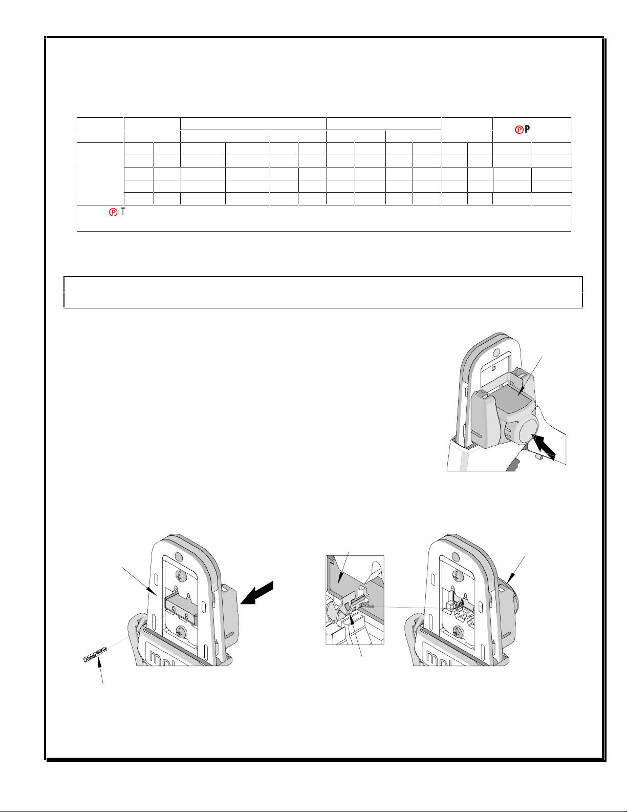
Crimping Terminals
1. Select the desired terminal listed in t he preceding chart s.
2. Make sure the center of the locator is in the down positi on. With the locator
attached, push the locator but ton on the back of the hand tool t o bri ng t he
locator forward through the tooling. See Figure 2.
3. While holding the locator button in, l oad the terminal into t he proper nest
opening in the locator based on the wi re gauge or t erm i nal t ype m arkings on
the hand tooling. S ee Figure 3.
LOCATOR
PUSHED THRU
TOOLING
LOCATOR
LOCATOR
BUTTON
PUSHED IN
INAL
TERMINAL
Figure 3
Figure 2
PUSH ON THE
LOCATOR BUTTON
RELEASE
LOCATOR BUTTON
Doc No: ATS-63819-0200 Release Date: 11-02-07
Revision: A Revision Date: 11-02-07
UNCONTRO L L ED CO P Y Page 2 of 7
Page 3
Hand Crimp Tool For C-Grid III™ Female Crimp Terminals
WIRE STOP IS PART
FIRST RATCHET
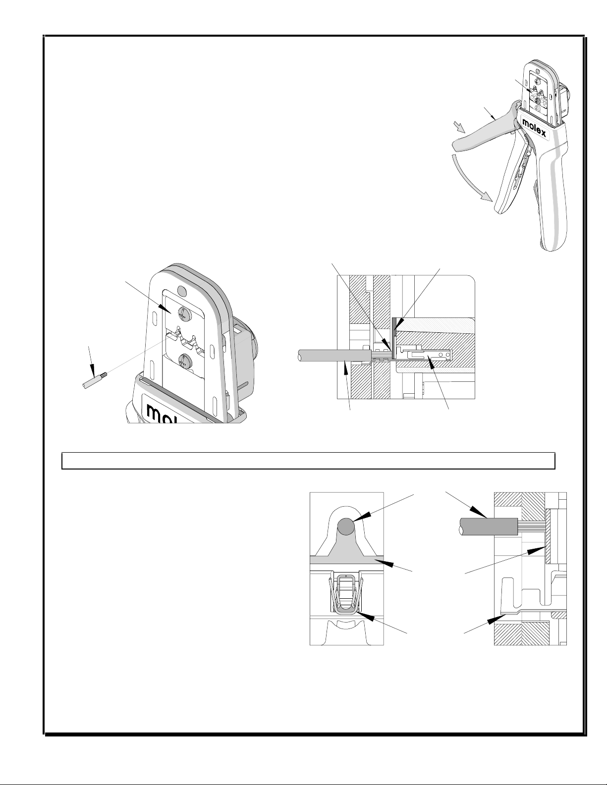
4. Release the locator button, allowing t he l ocat or t o ret urn to the crimping
position.
5. Close the tool handle until the first rat chet position engages. See
Figure 4.
6. Insert the properly stripped wire through the term i nal and agai nst the
wire stop. See Figure 5.
7. Crimp the terminal by squeezing the tool handles until the ratchet
mechanism cycle has been completed. Release the handles t o open
the jaws.
OPEN
POSITION
TERMINAL
WIRE AGAINST THE
WIRE STOP
OF THE LOCATOR
PRE-STRIPPED
WIRE
Figure 5
WIRE
TERMINAL
Note: The tamper proof ratchet action will not release the tool unt il it has been f ully closed.
WIRE
8. Remove the crimped terminal from the t erm inal
locator by pulling on the wire.
9. Visually inspect the crimped terminal for proper
crimp location.
10. On some large O.D. wi res, it may not be possible
to insert the wire wi th the tool partial l y closed.
WIRE STOP
Those wires should be inserted with the hand tool
in the open position. Insert the wire above the
terminal in the punch and against the wire stop
Figure 6
then close the tool. S ee Figure 6.
TERMINAL
TOOLING
PARTIALLY
CLOSED
PARTIALLY
CLOSE HANDLE
POSITION
Figure 4
Doc No: ATS-63819-0200 Release Date: 11-02-07
Revision: A Revision Date: 11-02-07
UNCONTRO L L ED CO P Y Page 3 of 7
Page 4

Hand Crimp Tool For C-Grid III™ Female Crimp Terminals
TOOLING
LOWER TABS
Note:
A crimp height chart is provided with this manual as Reference Only.
Due to the wide range of wires, st rands,
insulation diameters, and durom et ers avail able, actual crimp height measurement s may very slightl y. A n
occasional, destructive, pull f orce t est should be performed to check hand tool crimp. Pul l Force value Must
exceed the Minimum pull f orce specifi cat ions l ist ed.
LOCATOR
Locator Replacement
See the parts list on t he l ast page of this
document for the proper locat or order num ber.
Follow the steps below to replace t he l ocat or.
1. Open the crimp hand tool.
SQUEEZE
HERE
Figure 7A
2. Squeeze gently on the lower area shown in
Figure 7A with your thumb and i ndex fi nger.
The lower tabs of the locator should
disengage from the hand tool.
3. Lift and pull away from the hand tool. The
top locator hooks should slip out of t he t op
slots easily. See Figure 7A.
4. To reinstall the new locator, make sure the
hand tool is in the open position.
5. Press the red insert down as far as it will go
as shown in Figure 7B.
6. Holding onto the lower part of the locat or wi th your thumb and index finger, i nsert the locators top hooks (2)
into the hand tool t op slots.
7. Rotate the locator down and press the lower tabs into the two bottom slots of the hand tool. To secure the
locator into place, the lower tabs must snap into
place on the hand tool frame.
Right or Left Hand Operation
This hand tool has an added feature that can be
converted from a right handed applicat ion to a left
handed application. It is necessary to reverse the
M3 BHCS
tooling if using t he left handed application along wit h
the locator. Follo w t he st eps below:
1. The locator must be removed before reversing
the tooling.
2. Remove the M3 BHCS which is holding the upper
tooling.
3. Flip the upper tooling to the opposite side and
replace the M3 BHCS. M ake sure t he smal l
markings on the front and back of the hand t ool f ram e, m atch up and are on the outside of the hand tool frame.
See Figure 8 and 9.
SQUEEZE
HERE
TOP SLOTS OF
HANDTOOL
TOP HOOKS
JAWS OPEN
PULL OPEN
Figure 8
PUSH ON
HANDLE
MAKE SURE
CENTER OF LOCATOR
IS IN THE
DOWN POSITION
Figure 7B
TOOLING
Doc No: ATS-63819-0200 Release Date: 11-02-07
Revision: A Revision Date: 11-02-07
UNCONTRO L L ED CO P Y Page 4 of 7
Page 5

Hand Crimp Tool For C-Grid III™ Female Crimp Terminals
LUBRICATION POINTS
4. Do the same thing with the lower tooli ng and t i ghten
the M3 screws. Be sure the small m arkings li ne up.
MATCH
UP MARKS
5. Reinstall the locator by following t he I nst ruct i ons in
the locator replacement secti on.
Figure 9
Maintenance
It is recommended that each operat or of the tool be
made aware of, and responsible for, the following
FRONT BACK
maintenance steps:
1. Remove dust, moisture, and other contaminant s with a clean brush, or soft, lint free cloth.
2. Do not use any abrasive materials that could damage the tool.
3. Make certain all pins; pivot points and bearing surfaces are protected
with a thin coat of hi gh quali ty machine oil. Do not oil excessively.
The tool was engineered for durability but like any other equipment it
needs cleaning and lubrication for a maxim um service lif e of trouble
free crimping. Light oi l (such as 30 weight aut om otive oil) used at the
oil points, every 5,000 crimps or 3 months, will significantly enhance
the tool life.
4. Wipe excess oil from hand tool, particularly from crimping area. Oi l
transferred from the crimpi ng area onto certain terminati ons may
affect the elect rical characteri st i cs of an appl icat i on.
5. When tool is not in use, keep the handles closed to prevent objects
from becoming lodged in the crimpi ng di es, and st ore the tool in a
(BOTH SIDES) LIGHT OIL
(EVERY 3 MONTHS OR
5,000 CRIM PS)
clean, dry area.
Figure 10
Miscrimps or Jams
Should this tool ever become stuck or jamm ed i n a part i al l y closed positi on, Do No t force the handles open or
closed. The tool will open easily by pressing up on the ratchet release lever in the movable handle. See Figure
11.
How to Adjust Tool Preload (See Figure 12)
This hand tool is factory preset to 25-45 LBS. preload. It may be necessary
over the life of t he t ool t o adj ust tool handle preload force. Listed bel ow are
the steps required to adjust t he crimpi ng f orce of the hand tool to obtain
proper crimp conditions:
1. Hold the hand tool in the palm of your hand as shown in Figure 10.
Using the index finger squeeze the link towards t he top of the hand tool
frame. This will release the preload adjustment wheel.
RATCHET RELEASE
LEVER
Figure 11
Doc No: ATS-63819-0200 Release Date: 11-02-07
Revision: A Revision Date: 11-02-07
UNCONTRO L L ED CO P Y Page 5 of 7
Page 6

Hand Crimp Tool For C-Grid III™ Female Crimp Terminals
RATCHET
2. Rotate the setting wheel counter-clockwise (CCW) to increase handle force. The numbers will display higher.
To decrease handle force rotate the sett i ng wheel clockwise (CW).
3. Release the link to lock the setting wheel in place.
4. Check the crimp specifications or
conduct a pull test aft er t ool handl e
preload force is adjusted.
RELEASE LEVER
SQUEEZE
THE LINK IN
THE HANDLE
HOLD THE HAND
TOOL IN POSITION
Warranty
This tool is for electrical t erm i nal crimpi ng
purposes only. This tool is made of the
best quality materi als. All vital
components are long life test ed. A l l tools
are warranted to be free of m anuf act uri ng
defects for a period of 30 days. S hould
such a defect occur, we will repair or
Figure 12
exchange the tool free of charge. This
repair or exchange will not be applicable
to altered, mi sused, or dam aged t ool s.
SETTING
WHEEL
This tool is designed for hand use only.
Any clamping, fixt uri ng, or use of handl e ext ensions voids thi s warrant y.
CAUTION: Mol ex crimp specif i cat ions are vali d onl y when used wit h M ole x term i nal s and t ool i ng.
CAUTIONS:
1. Manually powered hand tools are intended for low volume or fiel d repai r. This tool is NOT int ended for
production use. Repetiti ve use of t hi s t ool should be avoided.
2. Insulated rubber handles are not protection against electrical shock.
3. Wear eye protection at all times.
4. Use only the Molex terminals specified for crimping wi t h this tool.
Certification
Molex does not certify or re-certi f y hand t ool s but rather supplies the following gui del i nes f or custom ers t o re-cert i fy
hand tools.
%
This tool is qualified to pull force only. To re-certif y, crim p a terminal to a wire, whi ch has been stri pped
12.7mm (1/2”) long, so t here i s no crimpi ng of the insulation. Pu ll the terminal and wire at a rate no faster than
25mm (1.00”) per minute. See t he M ol ex web sit e for the Quality Crimp Handbook f or m ore i nf o rm at i on on pul l
testing.
%
If the tool does not m eet minimum pull f orce values, handle prel oad should be i ncreased and the pull test
rerun, (See How to Adj ust Preload).
%
When the hand tool is no longer capable of achieving m i nim um pul l f orce, i t should be taken out of service and
replaced.
Doc No: ATS-63819-0200 Release Date: 11-02-07
Revision: A Revision Date: 11-02-07
UNCONTRO L L ED CO P Y Page 6 of 7
Page 7

Hand Crimp Tool For C-Grid III™ Female Crimp Terminals
PARTS LIST
Item Number Order Number Description Quantity
REF 63819-0200 Hand Crimp Tool Figure 13
1 63819-0275 Locator Assembly 1
2 63810-0104 Spring, Return 1
3 63810-0105 Spring, Ratchet 1
Americas Headquar ters
Lisle, Illinois 60532 U.S.A.
1-800-78MOLEX
amerinfo@molex.com
1
Far East North Hea dquarters
Yamato, K anagawa, J apan
81-462-65-2324
feninfo@molex.com
Visit our Web site at http://www. molex.com
Figure 13
Far East South He adqua rters
Jurong, Singapore
65-6-268-6868
fesinfo@molex.com
2
RATCHET
RELEASE LEVER
3
European Headquarters
Munich, Germany
49-89-413092-0
eurinfo@molex.com
Corporate Headqua rters
2222 Wellington Ct.
Lisle, I L 60532 U.S.A.
630-969-4550
Fax: 630-969-1352
Doc No: ATS-63819-0200 Release Date: 11-02-07
Revision: A Revision Date: 11-02-07
UNCONTRO L L ED CO P Y Page 7 of 7
 Loading...