

Page 1

FineAdjust Applicator
Description
Operation
Maintenance
Doc. No: TM-638004900 Release Date: 09-04-03 UNCONTROLLED COPY Page 1 of 50
Revision: G Revision Date: 01-15-13
FineAdjust™ APPLICATOR
Operation Manual
Order No 63800-4900
Page 2
FineAdjust Applicator
Read
and
understand
all of the instructions and safety information in this manual
before
CAUTION:
WARNING
WARNING
Heavy Object
WARNING
WARNING
Never
install or service this machine while
WARNING
WARNING
Never
operate, service, install, or adjust this
This symbol is used to call your attention to hazards or unsafe practices which could result in an injury
or property damage. The signal word, defined below, indicates the severity of the hazard. The message
after the signal word provides information for preventing or avoiding the hazard.
DANGER
WARNING
Safety Warnings and Information
operating or servicing this tool.
Keep this manual available when using this tool.
Replacement manuals are available for download at no charge at www.molex.com.
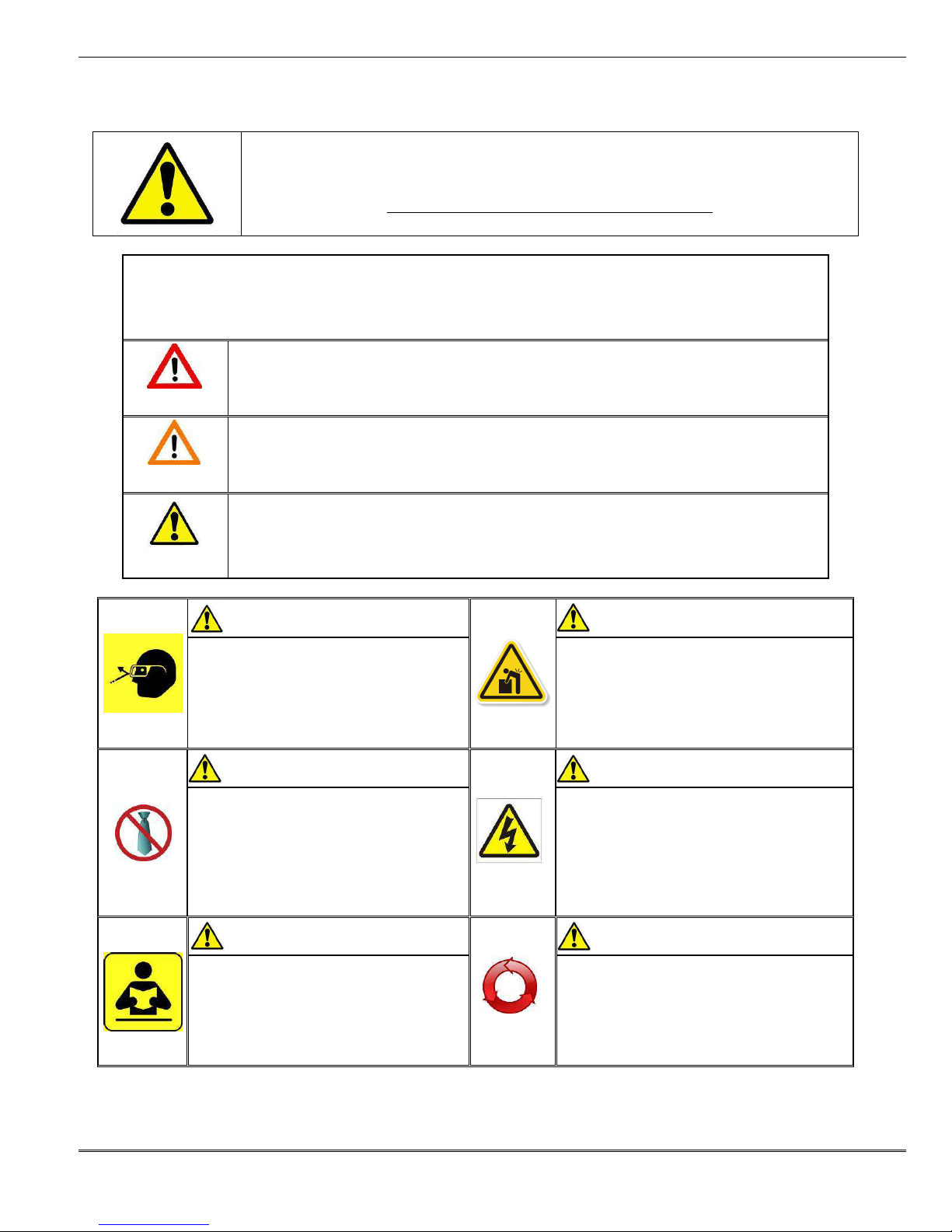
SAFETY ALERT SYMBOL
DANGER:
Indicates an imminently hazardous situation which, if not avoided, could result in death or serious injury.
WARNING:
Indicates a potentially hazardous situation which, if not avoided, could result in death or serious injury.
CAUTION
Indicates a potentially hazardous situation which, if not avoided, may result in minor or moderate injury.
CAUTION may also be used to alert against unsafe practices associated with events that could lead
to personal injury.
Always wear proper eye protection when
Operating or servicing this equipment.
Failure to wear eye protection could result
in serious eye injury from flying debris.
Never wear clothing or jewelery that is loose or
That could potentially hang into the equipement
and get caught.
Failure to observe this warning could result in
Severe Injury or death.
machine without proper instruction and without
first reading and understanding the instructions
in this manual and all applicable press and/or
wire processing machine.
manuals.
To avoid muscle strain or back injury, use lifting
aids and proper lifting techniques when removing
or replacing.
Failure to observe these precautions may result in
injury or property damage.
connected to any electrical power source.
Disconnect power by unplugging the press
from its power source.
Failure to observe this warning could result
In severe injury or death.
Always hand cycle the applicator in the equipment
to ensure the tooling is properly aligned.
Failure to observe these precautions may result in
Injury or property damage.
Doc. No: TM-638004900 Release Date: 09-04-03 UNCONTROLLED COPY Page 2 of 50
Revision: G Revision Date: 01-15-13
Page 3

FineAdjust Applicator
WARNING
WARNING
Do not use
compressed air to clean
WARNING
CAUTION
The Molex applicators a
re designed to operate in presses with standard shut heights of 135.80mm (5.346”).
CAUTION
Never
perform any se
rvice or maintenance other than as described in this manual.
Never use this press or wire processing machine
without guards or safety devices that are intended
to prevent hands from remaining in the die space.
Failure to observe this warning could result in
Severe injury or death.
Always wear proper ear protection when Operating or servicing this applicator.
Installation in crimp presses with other than standard shut heights can cause severe tool breakage. It is advisable that before
installation, a check of the shut height be performed. Molex will not be liable for any damages as a result of installation in a
crimp press with nonstandard or improperly set shut height.
Failure to observe these precautions may result in injury or property damage.
Never modify, alter or misuse the equipment
Molex crimp specifications are valid only when used with Molex terminals, applicators and tooling.
Failure to observe this precaution may result in injury and property damage.
this equipment.
The forces created by compressed
air can force debris into the tool.
Failure to observe these precautions may
result in injury or property damage.
Tooling Technical Assistance
Molex offers tooling technical assistance for customers who may need some guidance for tooling adjustments. This support can
be obtained by calling either of the two numbers listed below and asking for the Molex Tooling Group.
Call Toll Free 1-800-786-6539 (US) 1-630-969-4550 (Global).
This assistance is limited to the operation and set-up of a customer’s Molex Press. Questions with regard to Molex connector
products or how to identify the proper tooling and/ or tooling documentation should be directed to your local Molex personnel or
Customer Service Representative.
When calling for service on the press a copy of the Tooling Manual and Specific Applicator Tooling Specification Sheet should be
present and a person that is familiar with the applicator should be present. Be sure the following information is supplied:
1. Customer name
2. Customer address
3. Person to contact such as (name, title, e-mail, and telephone number
4. Applicator order number (Lease number also if applicable)
5. Serial number (Lease number also if applicable)
6. Molex Connector product order number
7. Urgency of request
8. Nature of problem
Molex Application Tooling Group
2200 Wellington Court
Lisle, IL 60532, USA
Tel: +1 (630) 969-4550
Fax:+1 (630) 505-0049
Visit our Web site at http://www.molex.com
Doc. No: TM-638004900 Release Date: 09-04-03 UNCONTROLLED COPY Page 3 of 50
Revision: G Revision Date: 01-15-13
Page 4

FineAdjust Applicator
Table of Contents
Contents
FineAdjust™ APPLICATOR .......................................................................................................................................... 1
Order No 63800-4900 .................................................................................................................................................... 1
Safety Warnings and Information .................................................................................................................................. 2
Table of Contents ........................................................................................................................................................ 4
Section 1 ................................................................................................................................................................... 6
General Description .............................................................................................................................................. 6
Principal Mechanical Parts of the FineAdjust Applicator ....................................................................................... 7
1.1 Description................................................................................................................................................. 8
1.2 Features .................................................................................................................................................... 8
1.3 Technical Specification .............................................................................................................................. 8
1.4 Delivery Check .......................................................................................................................................... 8
1.5 Tools .......................................................................................................................................................... 9
1.6 Specification Sheets .................................................................................................................................. 9
Section 2 ................................................................................................................................................................. 10
Set-Up and Operation ......................................................................................................................................... 10
2.1 Shut Height .............................................................................................................................................. 11
2.2 Set-Up ..................................................................................................................................................... 11
2.3. Adjustments ............................................................................................................................................. 13
2.4 Crimp Tooling Installation and Removal .................................................................................................. 16
Section 3 ................................................................................................................................................................. 18
Maintenance ....................................................................................................................................................... 18
3.1 Cleaning .................................................................................................................................................. 19
3.2 Lubrication ............................................................................................................................................... 19
3.3 Spare Parts.............................................................................................................................................. 20
3.4 Perishable Parts ...................................................................................................................................... 20
3.5 Storage .................................................................................................................................................... 21
Section 4 ................................................................................................................................................................. 22
Styles of FineAdjust ............................................................................................................................................ 23
4.1 STYLE A-FineAdjust Applicator ............................................................................................................... 24
4.1 STYLE A FineAdjust Applicator Assembly............................................................................................... 26
4.1 STYLE A FineAdjust Applicator Assembly (Cont.) ................................................................................... 27
4.2 STYLE B-FineAdjust Applicator ............................................................................................................... 28
4.2 STYLE B FineAdjust Applicator Assembly............................................................................................... 30
4.2 STYLE B FineAdjust Applicator Assembly (Cont.) .................................................................................. 31
4.3 STYLE C-FineAdjust Applicator ............................................................................................................... 32
4.3 STYLE C FineAdjust Applicator Assembly .............................................................................................. 34
4.3 STYLE C FineAdjust Applicator Assembly (Cont.) ................................................................................. 35
4.4 Troubleshooting ....................................................................................................................................... 36
Appendix A .............................................................................................................................................................. 38
Crimp Terminations ............................................................................................................................................ 38
A.1 Conductor Brush and Terminal Position ................................................................................................. 39
A.2 Conductor Bell Mouth and Terminal Cutoff Tab ....................................................................................... 40
A.3 Conductor Height Measurement .............................................................................................................. 41
A.4 Insulation Crimp ....................................................................................................................................... 41
A.5 Pull Force Testing .................................................................................................................................... 43
Appendix B .............................................................................................................................................................. 45
Doc. No: TM-638004900 Release Date: 09-04-03 UNCONTROLLED COPY Page 4 of 50
Revision: G Revision Date: 01-15-13
Page 5

FineAdjust Applicator
Statistical Process Control (Summary) ............................................................................................................... 45
B.1 Crimp Process Control ............................................................................................................................ 46
B.2 Process Capability ................................................................................................................................... 46
B.3 Production ............................................................................................................................................... 47
Appendix C ............................................................................................................................................................. 49
Options .................................................................................................................................................................... 49
Terminal Oiler ................................................................................................... Error! Bookmark not defined.50
Order No. 63890-0719 ...................................................................................... Error! Bookmark not defined.50
Doc. No: TM-638004900 Release Date: 09-04-03 UNCONTROLLED COPY Page 5 of 50
Revision: G Revision Date: 01-15-13
Page 6

FineAdjust Applicator
General Description
1.1 Description
1.2 Features
1.3 Technical Specifications
1.4 Delivery Check
1.5 Crimp Tooling Accessories
1.6 Tools
1.7 Specification Sheets
Section 1
Doc. No: TM-638004900 Release Date: 09-04-03 UNCONTROLLED COPY Page 6 of 50
Revision: G Revision Date: 01-15-13
Page 7
FineAdjust Applicator
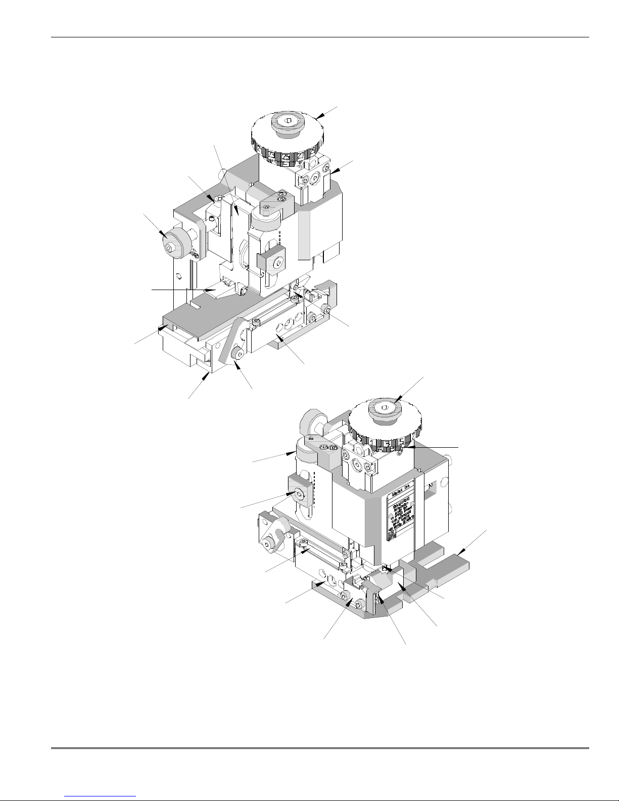
Figure 1
-1
PIVOT ARM
FORWARD FEED
FORWARD FEED
INSULATION
RAM
DRAG FRAME
DRAG RELEASE
TRACK
FEED FINGER
CONDUCTOR
BACK STROKE
LUG BOLT
WIRE STOP
ANVIL MOUNTING BLOCK
ANVILS
FRONT COVER
TRACK
CUT-OFF PLUNGER
FEED
FINGER
BACK STROKE
Principal Mechanical Parts of the FineAdjust Applicator
ADJUSTING KNOB
REAR COVER
LOCKING SCREW
LEVER
ADJUSTING KNOB
LOCKING SCREW
ADJUSTING SCREW
ADJUSTING CAM
ADJUSTING CAM
BASE PLATE
Doc. No: TM-638004900 Release Date: 09-04-03 UNCONTROLLED COPY Page 7 of 50
Revision: G Revision Date: 01-15-13
AND RETAINER
Page 8

FineAdjust Applicator
General Descrition
1.1 Description
The Molex FineAdjust™ Applicator is designed to provide
an effective method of applying a wide range of side feed
terminals to a pre-stripped discrete wire. It is the most
advanced version of a "universal" crimping tool available. It
is designed to allow for quick adjustments of crimp height,
track position, and terminal feed without taking the
applicator out of the press and without shimming. This
allows easy adjustment of crimp height to the target value
with improved process capability, even after a wire changeover.
This applicator works in the Molex TM-2000 and TM-3000
Universal Press and in most industry standard presses.
The FineAdjust™ applicator offers minimal setup time
without the need for shimming, is versatile, reliable, easy to
install, and is designed for mid-volume to high-volume,
semi or fully automatic operations.
Molex offers the following crimp presses for operating the
Fine Adjust Applicator™:
TM-2000 Press 120 V 60 Hz. 63800-8300
TM-2000 Press 240 V 50 Hz. 63800-8400
TM-3000 Press 120 V 60 Hz. 63801-7200
TM-3000 Press 240 V 50 Hz. 63801-7300
TM-4000 Press 240 V 60 Hz. 63801-7600
The FineAdjust Applicator is also compatible with most
OEM presses (Artos, Mecal, Komax, Megomat, Toyojamco,
etc). It also adapts to most wire processing machines.
1.2 Features
Fine adjustment allows users to achieve target with
little effort by adjusting in increments (14 settings) of
.015mm (.0006") for conductor crimp height and (29
settings) in increments of .063mm (.0025") for
insulation height.
Independent adjustment rings allow users to quickly
adjust the conductor or insulation crimp height without
affecting each other.
Quick tooling removal with the push of a button for fast
and easy punch change.
Track adjustment for bell mouth and cut-off tab is
adjusted while the applicator is in the press for fast and
easy setup.
Compatible with the Molex TM-2000, TM-3000, TM-
4000 Universal Press, and most industry standard
presses. However, it does NOT fit into Molex TM40/42 press.
Directly adapts to most automatic wire processing
machines.
Quick set-up time; plus the crimp height, track and feed
adjustments can be preset in applicator.
Applicator designed to industry standard mounting and
shut height 135.80mm (5.346").
Automatic terminal feed with applicator in press.
Adjustable terminal feed with applicator in press.
Terminals are separated from carrier strip automatically
during crimping operation.
Quiet operation with low maintenance and easy to
keep clean.
The FineAdjust™ available for most Molex brand
terminals.
1.3 Technical Specification
Dimensions
Width: 132mm (5.2")
Depth: 101mm (4.0")
Height: 152mm (6.0")
Weight
4.1kg (9lbs)
Press Stroke Compatibility
41.28mm (1 5/8")
28.58mm (1 1/8")
Guarding
The FineAdjust™ Applicator is supplied with no
guards and is intended to be used with the guards
supplied by the press manufacturer.
Caution: DO NOT use the applicator
without guards
1.4 Delivery Check
Carefully remove the FineAdjust Applicator from its
shipping container and determine that the following
items are included in the package.
FineAdjust Applicator 1
(Tooled for desired terminal)
11-18-4238 Short Feed Cam 1
Specification Sheets 1
TM-638004900
Operation Manual 1
Sample Crimped Terminals 5
Crimp Tooling Accessories
Doc. No: TM-638004900 Release Date: 09-04-03 UNCONTROLLED COPY Page 8 of 50
Revision: G Revision Date: 01-15-13
Page 9
FineAdjust Applicator
63890-0719 Terminal Oiler (Appendix C)
63800-2800 Digital Crimp Micrometer
1.5 Tools
The following tools are recommended for setup and
adjustments to the applicator:
1. Metric standard hex wrench set
2. Adjustable wrench
3. Wire stripper / cutter
4. Scissors
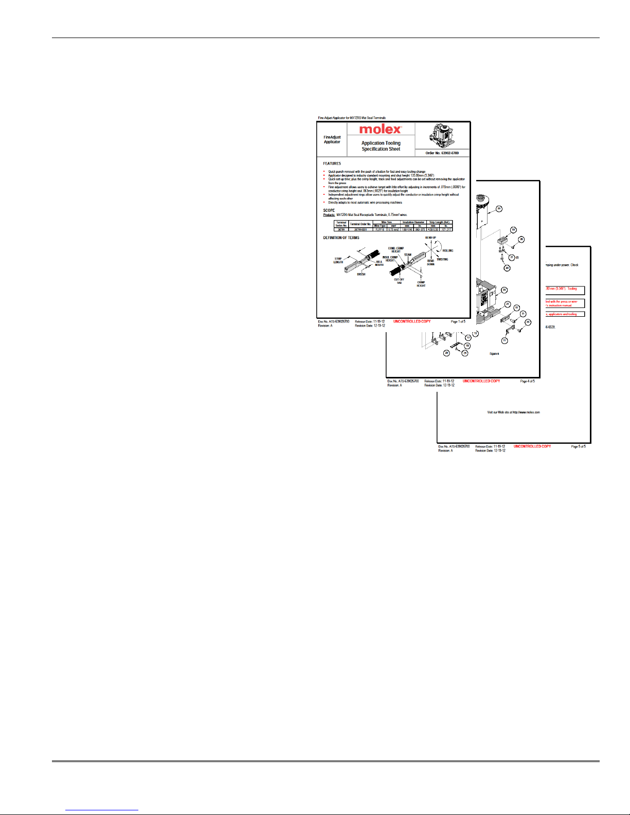
1.6 Specification Sheets
Molex ships specification sheets with every
applicator. The specification sheet contains the
following:
ΕΕΕΕ Terminal numbers
ΕΕΕΕ Wire AWG ranges
ΕΕΕΕ Insulation diameter ranges
ΕΕΕΕ Strip lengths
ΕΕΕΕ Pull force
ΕΕΕΕ Crimp heights
ΕΕΕΕ Bell mouth
ΕΕΕΕ Bend, twist, and roll limits
ΕΕΕΕ Tooling parts list and assembly
The specification sheet should be filed. These are
available on the Molex website (www.molex.com).
Doc. No: TM-638004900 Release Date: 09-04-03 UNCONTROLLED COPY Page 9 of 50
Revision: G Revision Date: 01-15-13
Page 10

FineAdjust Applicator
Section 2
Set-Up and Operation
2.1. Shut Height
2.2. Set-Up
2.3. Adjustments
2.4. Crimp Tooling Installation and Removal
Doc. No: TM-638004900 Release Date: 09-04-03 UNCONTROLLED COPY Page 10 of 50
Revision: G Revision Date: 01-15-13
Page 11
FineAdjust Applicator
PRESS
PRESS QUICK
SHUT HEIGHT
Read the following instructions before attempting to operate the applicators.
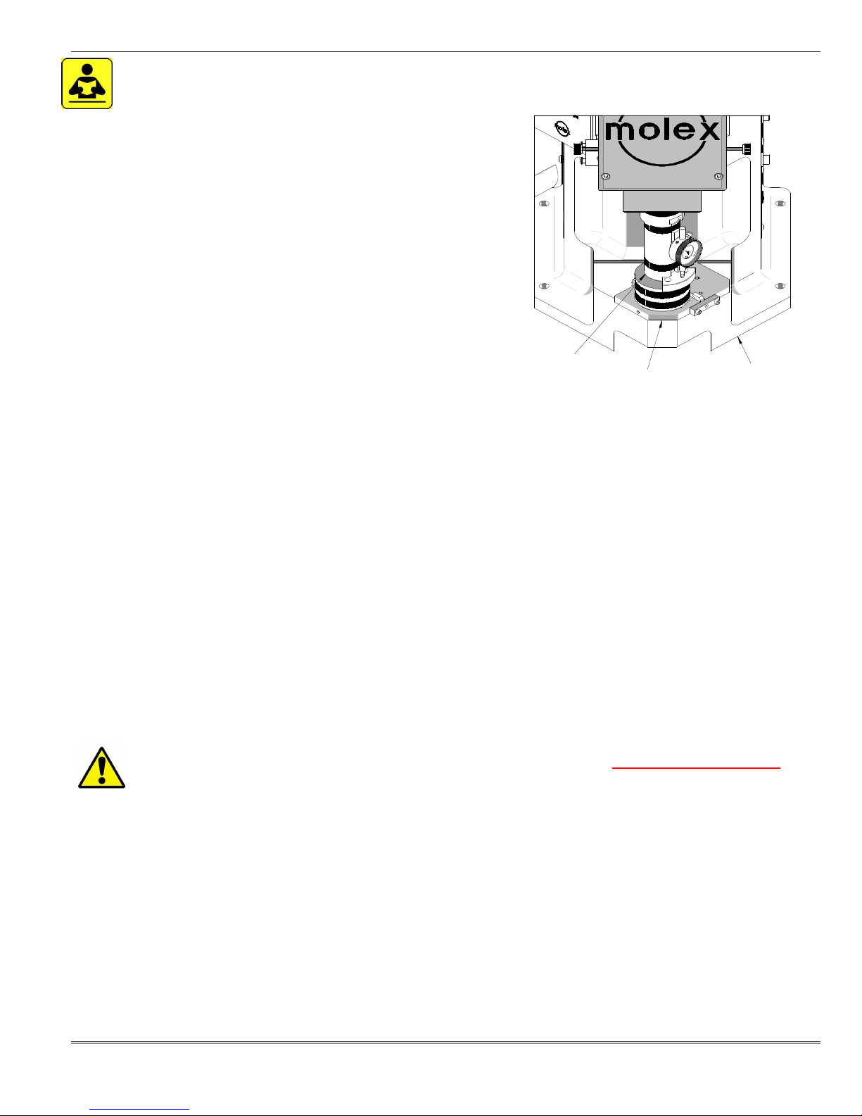
2.1 Shut Height
The Molex FineAdjust Applicators are designed to operate in crimp
presses with standard shut height of 135.80mm (5.346").
Installation in crimp presses with other than standard shut heights
can cause severe tool breakage. It is recommended that before
installation, a check of the shut height be performed. The correct
shut height is required to prevent the punches from hitting the anvils
and the cut-off tooling from bottoming out on the base plate. It also
allows the movement of applicators from press to similar press
without adjusting the applicator or press shut height.
The shut height of the press can be checked with a shut height
gauge, which is calibrated under load to achieve the 135.80mm
(5.346") measurement. It is recommended that the shut height be
checked monthly. A shut height gauge is available from most press
manufacturers.
Measuring Press Shut Height
GAUGE
CHANGE
MOUNTING PLATE
Figure 2-1
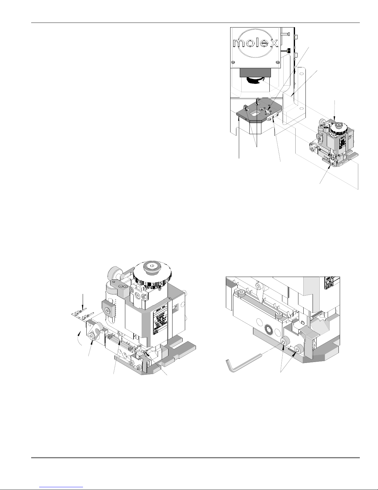
1. Always disconnect the power supply from the press. Remove the machine guards if necessary.
2. Remove the applicator from the press. See “Applicator Installation and Removal” (below) for additional information. Make
sure that the bottom of the press ram and quick change mounting plate are free from foreign material.
3. Place the shut height gauge into the press on the press quick change mounting plate. See Figure 2-1.
4. Manually cycle the press to the down stroke position. (Follow press manufacturer’s instructions on manually cycling the
press.)
5. Read the shut height measurement from the front of the gauge. Follow gauge manufacturers’ instruction, usually the gauge
reads “0” when set correctly.
6. If adjustments are necessary, refer to the press manufacturer for adjustment of the press shut height.
7. Repeat the above steps until the correct shut height is obtained.
8. Shut height gauges must be calibrated on a regular basis.
2.2 Set-Up
IMPORTANT
Power must be shut off and electrical cord disconnected. Manual press cycling is an absolutely required procedure
for safety and preventing equipment damage. Always cycle by hand when trouble shooting or changing adjustments,
tooling, applicator, or accessories.
The principal mechanical parts of the FineAdjust are illustrated in Section 4.1 Assembly Drawings.
Applicator Installation and Removal
1 All presses must be equipped with a common universal type quick-change mounting plate and adapter on the press.
Contact the press manufacturer for specific information.
2 Always turn off and disconnect the power supply to the press. Remove the press guards.
3 Clean the quick change mounting plate of scrap or chips that may interfere with the FineAdjust applicator installation.
4 For the TM-2000 and TM-3000 Presses follow the procedure below:
a. Using a 4mm hex wrench, turn the M5 SHCS clockwise until the locking clamp is fully opened.
b. Visually align the applicator base plate slots with the location clamps on the press quick-change mounting plate.
Doc. No: TM-638004900 Release Date: 09-04-03 UNCONTROLLED COPY Page 11 of 50
Revision: G Revision Date: 01-15-13
Page 12
FineAdjust Applicator
ENGAGE PRESS
BASE PLATE
LOCKING CLAMP
QUICK
LOCATOR
TERMINAL
FEED FINGER
1ST
TERMINAL
c. Slide the applicator onto the quick-change mounting plate
until the two notches on the left side engage against the
stops, and at the same time, guide the lug bolt into the
adapter on the press. See Figure 2-2.
d. To lock applicator, turn the M5 SHCS counter clockwise until
tight.
YOKE
5 Some presses have locking latches on the quick change
mounting plate, which have to be flipped up to secure the
applicator. Others have knurled finger screws or "T" type latches.
APPLICATOR
Most of these are located on the right side of the quick change
mounting plate to secure the position of the applicator. These
must be in place and secured before operating the press.
6 Replace the press guards.
Remove the applicator by reversing the previous steps. When storing
an applicator, always leave a strip of terminals in the applicator to
prevent damage to the tooling. See Section 3.5 Storage.
Fitting Terminal Strip
1. The specified terminals are printed on the setup sheet for the
applicator. Only use the Molex terminals on the setup sheet
CHANGE
MOUNTING
PLATE
CLAMPS
M5 SHCS
Figure 2-2
which is supplied with the applicator.
2. Always disconnect the power supply from the press. Remove the machine guards if necessary.
3. Rotate the drag release until the drag frame is in the upright position. This will allow the terminal to slide with ease through
the applicator track. See Figure 2-3.
4. Push the terminal strip until the first terminal comes to rest centered above the anvil.
5. Rotate the drag release to engage the terminal drag frame.
6. Cycle the press by hand so that the feed finger transfers the next terminal to a centered position over the anvil. Check that
all other parts slide and engage without any interference. It is recommended to go through this procedure several times.
STRIP
Figure 2-4
DRAG RELEASE
Figure 2-3
CENTERED
ABOVE ANVILS
RELEASE M4 SHCS
7. When unloading the terminal strip, make sure the power is turned off and disconnected from the press. Remove the
machine guards if necessary.
8. Rotate the drag release until the drag frame is in the upright position.
9. Raise feed finger and pull terminal strip back until disengaged from applicator track. See Figure 2-3. If preferred, cut the
terminal carrier strip and pull it through the applicator with needle nose pliers.
10. Replace the machine guards before operating the press.
Doc. No: TM-638004900 Release Date: 09-04-03 UNCONTROLLED COPY Page 12 of 50
Revision: G Revision Date: 01-15-13
Page 13
FineAdjust Applicator
APPLICATOR
6mm X 20mm
M6 X 10mm
M10
TERMINAL
M4 X 12mm
DRAG RELEASE
Punch and Anvil Alignments
Note: Always clean mounting surfaces of crimp tooling and tooling holders before
alignment.
1. Always disconnect the power supply from the press. Remove the machine
guards if necessary.
2. With a terminal in position over the anvils, slightly release anvil mounting
screw. See Figure 2-4.
3. Gently hand-cycle the ram of the press to bottom of its stroke. Tighten anvil-
DOWEL PIN (2)
mounting screws in this position to ensure perfect alignment of punches and
anvils.
4. Hand cycle the press ram to the highest position.
BASE PLATE
5. Replace the machine guards before operating the press.
2.3. Adjustments
Cover Plate Adjustments
1. Always disconnect the power supply from the press. Remove the machine
Figure 2-5
BHCS (2)
guards if necessary.
2. Remove the applicator from the press. Refer to Applicator Installation and Removal.
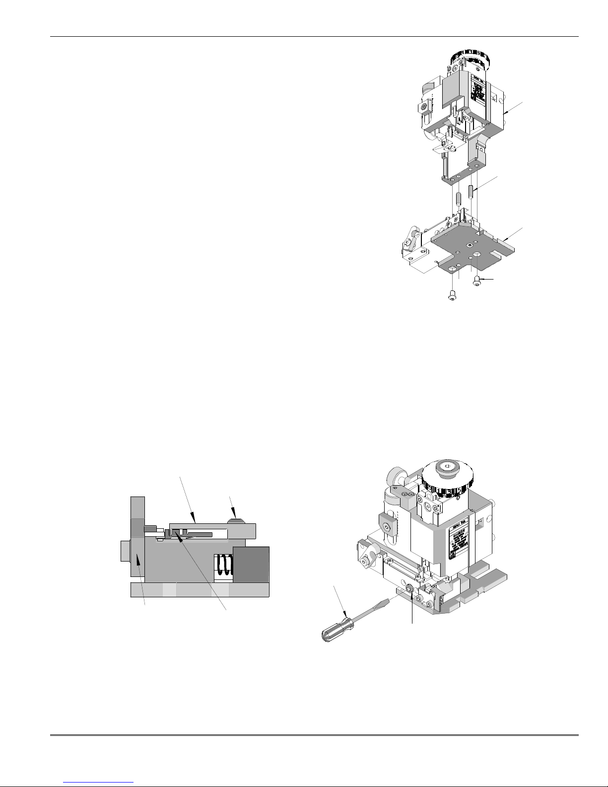
3. Rotate the drag release until the drag frame is in the upright position. The rear cover plate should be adjusted so that the
terminal strip will slide smoothly through the track with no resistance.
4. Some applicators require the removal of the applicator frame from the base plate. This is done by removing the two M6
BHCS located on the bottom of the base plate. See Figure 2-5.
5. Loosen the two M4 BHCS to adjust the position of the rear cover. See Figure 2-6.
6. Slide terminal strip through the track to ensure accurate cover positioning.
7. After the correct position is achieved, tighten the two M4 BHCS.
8. Reattach the applicator frame to the base plate if needed. Locate the position of the frame using the dowel pins. Tighten
the two M6 BHCS to secure the frame to the base plate.
REAR COVER
BHCS (2)
SCREWDRIVER
UP POSITION
Figure 2-6
LOCK SCREW
Figure 2-7
Track Position Adjustment
1. Disconnect power from the press. Remove the machine guards if necessary.
2. To position the terminal track in or out, first use a 6mm hex wrench to loosen the M10 lock screw located on the front of the
track.
Doc. No: TM-638004900 Release Date: 09-04-03 UNCONTROLLED COPY Page 13 of 50
Revision: G Revision Date: 01-15-13
Page 14
FineAdjust Applicator
Press St
roke
mm In.
Figure
2-9
FEED FINGER
FEED FINGER
TERMINAL
Figure 2
-8
PUSH DOWN
3. Put a regular screwdriver through the hole in the lock screw and turn the adjusting screw to position the terminal in the
correct location. See Figure 2-7. Turning the screw clockwise will move the track towards the operator; to move the track
towards the applicator turn the screw counterclockwise. Depending on the amount of movement, the feed finger mount may
need to be loosened and readjusted. See Feed Finger adjustment.
7 To lock the track in position, tighten the M10 lock screw.
8 If the feed finger mount was loosened during the track positioning, remember to tighten its mounting screw.
9 Replace machine guards.
10 Hand cycle the press to ensure the terminal is positioned properly on the anvils and does not have an excessive cutoff tab.
Also, verify the terminal feed operation.
11 Restore power to the press, crimp a terminal under power, and observe the quality of the termination.
12 Repeat the above steps until the desired terminal position is obtained.
Feed Finger Adjustments
M3 SHCS
1. Position the feed finger to properly feed the next terminal in
position. Typically, terminals are fed by the carrier strip.
2. Depending on the feed cam installation (pre-feed or postfeed), move the press ram until the feed is forward (this makes
the feed finger mount more accessible), and then disconnect
power from the press. Remove the machine guards if
necessary.
3. Using a 2.5mm hex wrench, loosen the M3 SHCS located on
the feed finger mount. While holding the feed finger lever
down slightly, slide the feed finger to the desired position. See
Figure 2-8.
LEVER
FEED FINGER
MOUNT
4. If the feed finger mount cannot be moved far enough, remove
the M3 SHCS completely and install it in another tapped hole
in the feed finger lever. In addition, the feed finger mount can be reversed (the feed finger must be reversed as well) to gain
additional adjustment.
5. Tighten the M3 SHCS to lock the feed finger in position.
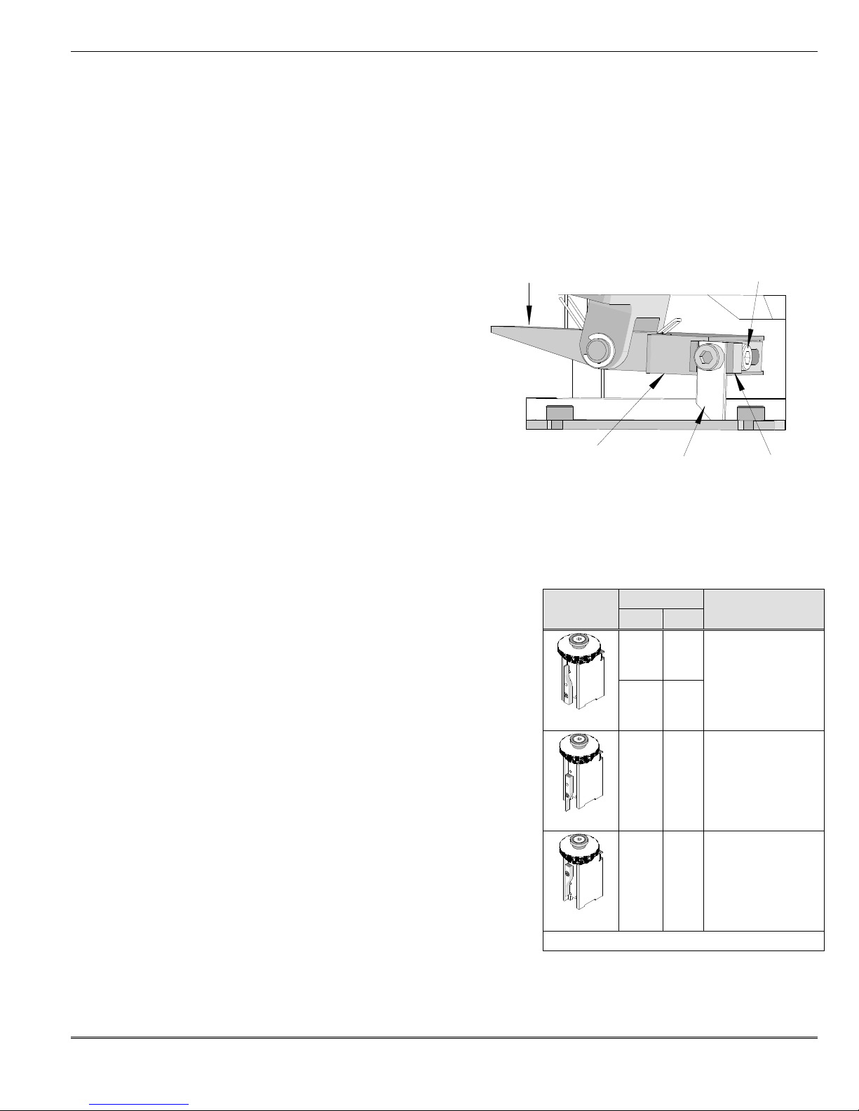
Feed Stroke Cam Adjustments
1. The terminal feed stroke is driven by a cam mounted to the applicator
ram. Two feed cams are shipped with the applicator. The standard cam
is installed in the applicator. The spare cam is for presses with short
strokes (for example, 28mm). Using the standard cam with a shortstroke press may result in insufficient feed stroke or incorrect feed
timing.
2. Determine what feed timing is desired. Typically, when the applicator is
mounted in a wire processing machine, the feed stroke cam should be
assembled in the down stroke position. While the press is idle in the up
position, a terminal will not be present over the anvil. For most bench
applications, the cam is installed in the up stroke position. This will leave
a terminal over the anvil when the press is idle in the up position. See
Figure 2-9.
3. Turn off and disconnect the power supply from the press. Remove the
machine guards if necessary.
4. Remove the applicator from the press. See Applicator Installation and
Removal.
5. Pull back on the feed pivot lever and remove the ram from the applicator.
6. Holding on to the ram, use a 3mm hex wrench to remove the M4 SHCS
holding the cam on the back of the ram.
7. Position the cam in the desired position for feeding and attach with the M4 screw. See Figure 2-9.
Feed Cam
Order No.
63800-0305
63800-0305
11-18-4238
41.28 1-5/8
28.58 1-1/8
41.28 1-5/8
28.58 1-1/8
Feed Timing
Up stroke
(terminal present
over anvil)
Down stroke
(terminal not present
over anvil)
Down stroke
(terminal not present
over anvil)
Doc. No: TM-638004900 Release Date: 09-04-03 UNCONTROLLED COPY Page 14 of 50
Revision: G Revision Date: 01-15-13
Page 15
FineAdjust Applicator
PIVOT CLAMP
FORWARD
M5 SHCS
BACK
Figure 2
-11
INSULATION
CONDUCTOR
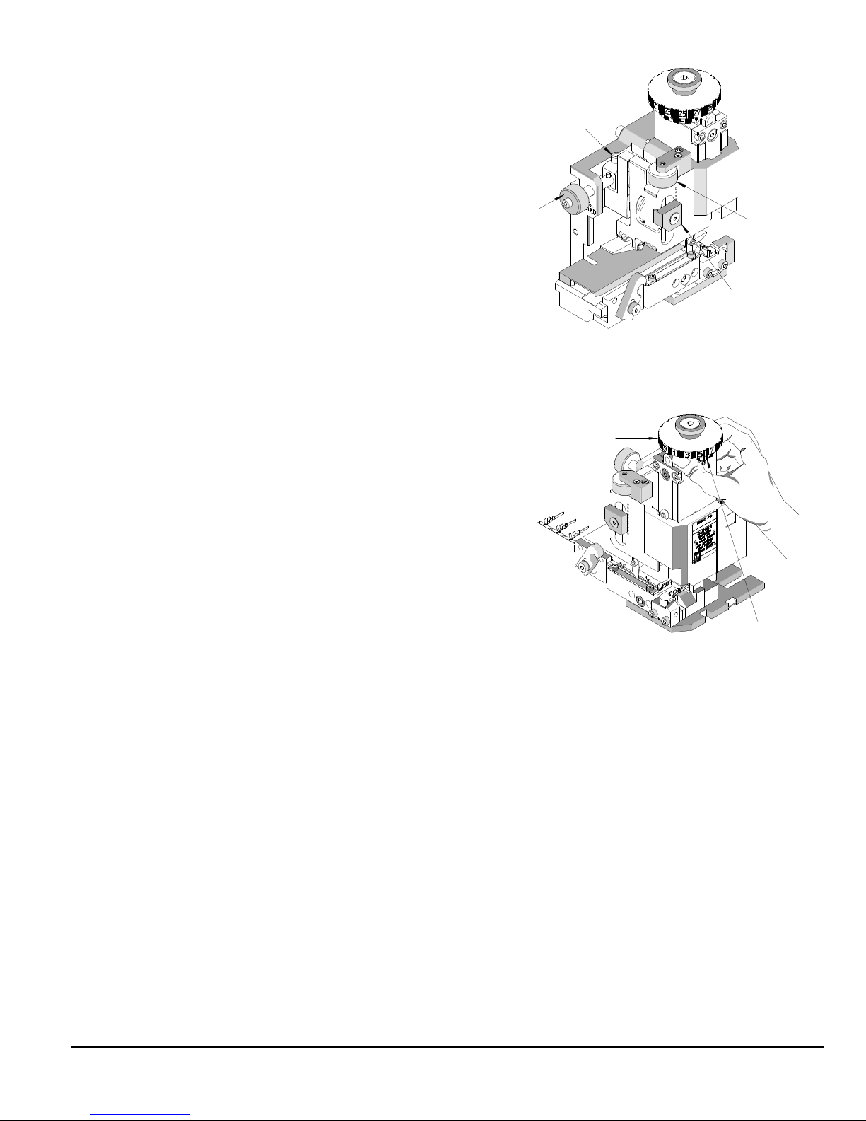
Forward Feed Adjustments
1. The forward feed position must locate the terminal that is
FEED LOCK
being crimped exactly over the anvils.
2. Disconnect the power from the press. Remove the
machine guards if necessary.
3. Make sure there is a terminal over the anvils and the feed
finger is fully forward (closest to the anvils).
4. Loosen the M5 SHCS.
5. Turn the forward feed adjusting knob to position the
FEED
STROKE
ADJ. KNOB
STROKE
ADJ. KNOB
terminal. To decrease the feed position, turn the forward
feed adjusting knob clockwise. To increase the feed
position turn the forward feed adjusting knob
counterclockwise. See Figure 2-10.
6. When adjusting to decrease the feed position, it is
Figure 2-10
M5 FHCS
necessary to pull the terminal strip backwards until it is against the feed finger. When increasing the feed position, the feed
finger will push the terminal farther over the anvils.
7. After properly adjusting the forward feed position of the terminal, tighten the M5 SHCS with a 4mm hex wrench.
Back Stroke Feed Adjustments
CAM (TOP)
1. To properly feed the terminal strip, the back feed stroke should have
enough over-travel to pick up the next terminal. Too much over
travel may, in some cases, cause a double-feed.
2. Disconnect the power from the press. Remove the machine guards if
necessary.
3. To achieve the correct backstroke location, adjust the position of the
hinge bushing. First, use a 3mm hex wrench to loosen the M5 FHCS
holding the pivot clamp. Turning the backstroke adjustment knob
(which is located above the hinge bushing) clockwise will raise the
hinge bushing and will increase the backstroke. Turning the knob
counter clockwise (CCW) will lower the hinge bushing and will
CAM (BOTTOM)
decrease the feed backstroke. When adjustment is complete, tighten
the pivot clamp securely. See Figure 2-10.
4. Since back feed stroke adjustment may not be visibly obvious, the terminal feed should be cycled (by hand, if possible) to
observe the changes.
5. Back feed stroke adjustments may affect the entire feed linkage; re-adjustment of the forward feed stroke could be
necessary. See Forward Feed Adjustments.
Conductor Crimp Punch Adjustments
1. With the guards intact, place a stripped length of suitable wire into the terminal and terminate the wire under power.
2. Inspect the quality of conductor crimp and measure the crimp height. See Appendix A.3 Conductor Crimp Height
Measurement.
3. If adjustments are necessary, turn off and disconnect the power supply from the press. Remove the machine guards.
4. The desired crimp height can be achieved by rotating the conductor-adjusting cam. See Figure 2-11. Each increment
represents approximately 0.015mm (.0006") for a total adjustment of 1.80mm (.071"). The "A" setting is the loosest crimp
height and the "N" setting is the tightest. If you find that the crimp height is not acceptable, you can rotate the adjusting cam
until the desired crimp height is obtained. See Section 2.1, Shut Height. No shimming of the applicator is required.
5. Replace the machine guards and repeat the previous steps until the desired crimp height is obtained. See Appendix A.3,
Conductor Crimp Height Measurement.
6. Perform a pull test on conductor crimp to verify the mechanical integrity of the crimp. See Appendix A.5, Pull Force Test.
Doc. No: TM-638004900 Release Date: 09-04-03 UNCONTROLLED COPY Page 15 of 50
Revision: G Revision Date: 01-15-13
Page 16
FineAdjust Applicator
Figure 2
-12
WIRE STOP
M5 SHCS
RAM
PUNCH RELEASE
Insulation Crimp Punch Adjustment
1. Place a stripped length of the appropriate wire into the terminal and
crimp under power.
2. Observe quality of insulation crimp and measure the crimp height.
See Appendix A.4, Insulation Crimp.
3. If adjustments are necessary, always turn off and disconnect the
power supply from the press. Remove the machine guards.
4. Rotate the insulation-adjusting cam to achieve the desired insulation
height. Each increment represents approximately 0.06mm (.0025") for
a total adjustment of 3.00mm (.118"). The "1" setting is for the highest
(most loose) crimp height and the "29" setting the lowest (most tight)
crimp height.
5. Repeat the previous steps until the desired insulation height is
obtained.
Note: Due to the large variety of insulation wall thickness, materials, and diameter, Molex does not specify insulation crimp
height. For each different wire type, the insulation crimp height can be measured, recorded, and inspected as a quality indicator.
Wire Stop Adjustment
For automatic wire processing machines, the wire stop can be used to assist in the stripping of the terminal from the punches.
However, in certain circumstances the wire stop will need to be removed when running on an automated machine.
1. Check the setup documents to obtain the correct strip length.
2. Place the correct wire into the terminal and crimp the wire under power.
3. Observe quality of crimp and the wire position. See Appendix A.1 Conductor Brush and Terminal Position.
4. If adjustments are necessary, turn off and disconnect the power supply from the press. Remove the machine guards.
5. Use a 4mm hex wrench to loosen the M5 SHCS located on the side of the frame. See Figure 2-12.
6. Adjust the position of the wire stop by moving the wire stop, towards the operator decreases the brush length and towards
the press increases it.
7. Tighten the M5 SHCS.
8. Hand cycle the press to ensure the applicator is functioning properly. Then crimp a terminal under power and observe the
quality of the termination.
2.4 Crimp Tooling Installation and Removal
Installation and Removal of the Upper Tooling (Punches)
Caution: Always disconnect power supply before installing or
removing tooling.
SCREWDRIVER
NOTE: Always clean mounting surfaces of crimp tooling and tooling holders
before installation.
1. Always turn off and disconnect the power supply from the press. Remove
the machine guards if necessary.
2. Remove the applicator from the press. See Section 2.2, Applicator
Installation and Removal.
3. Pull back the feed arm and remove the ram from the applicator.
4. With a small screw driver, push in the punch release button located on the front of the ram. See Figure 2-13.
5. Pull the punches out the bottom of the ram.
6. Reverse the previous steps to reinstall the punches.
BUTTON
PUNCHES
Figure 2-13
Doc. No: TM-638004900 Release Date: 09-04-03 UNCONTROLLED COPY Page 16 of 50
Revision: G Revision Date: 01-15-13
Page 17

FineAdjust Applicator
REMOVE M4 SHCS
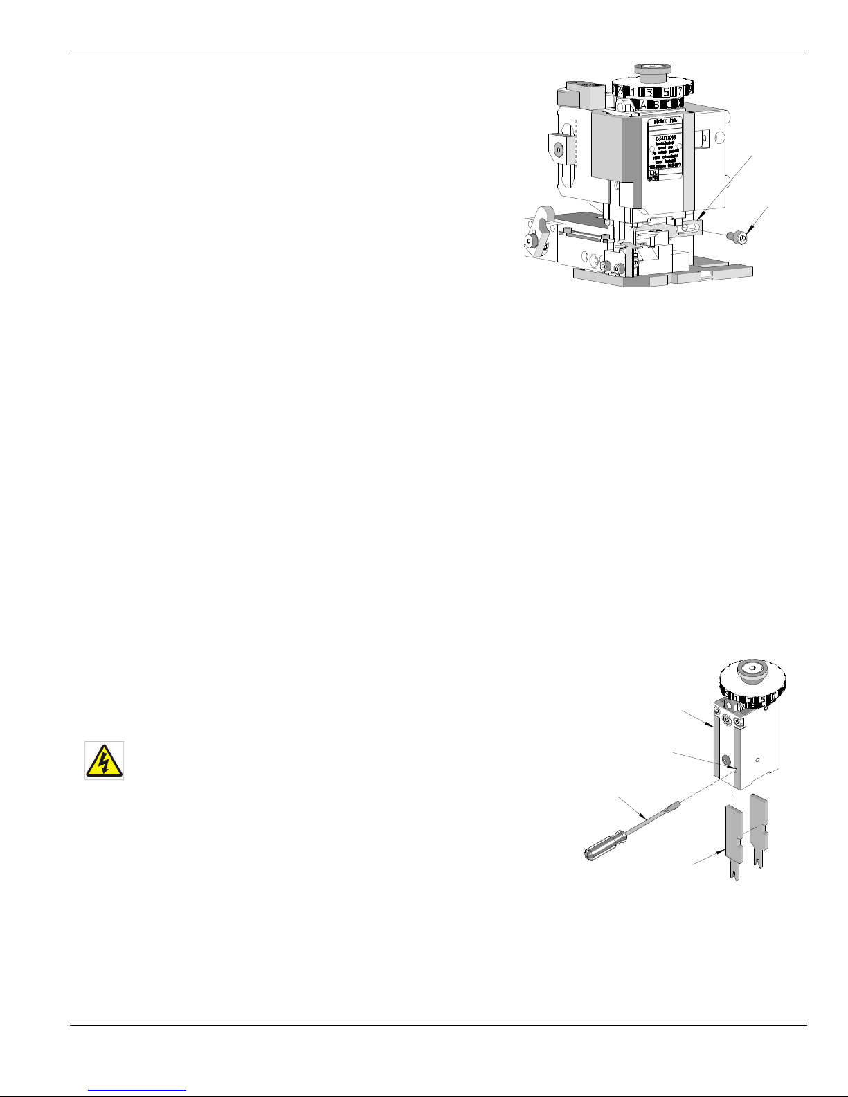
Installation and Removal of the Lower Tooling (Anvils)
Caution: Always disconnect power supply before installing or
removing tooling.
NOTE: Always clean mounting surfaces of crimp tooling and tooling holders
before installation.
1. Always turn off and disconnect the power supply from the press.
Remove the machine guards if necessary.
2. Make sure the ram is all the way in the up position.
3. Remove the M4 SHCS that are holding the lower tooling in place and pull
out the tooling. See Figure 2-14.
4. Put in the new anvils, leaving the mounting screws loose. For tightening,
see Section 2.2, Punch and Anvil Alignment.
Figure 2-14
Doc. No: TM-638004900 Release Date: 09-04-03 UNCONTROLLED COPY Page 17 of 50
Revision: G Revision Date: 01-15-13
Page 18

FineAdjust Applicator
Maintenance
3.1 Cleaning
3.2 Lubrication
3.3 Spare parts
3.4 Perishable Parts
3.5 Storage
Section 3
Doc. No: TM-638004900 Release Date: 09-04-03 UNCONTROLLED COPY Page 18 of 50
Revision: G Revision Date: 01-15-13
Page 19

FineAdjust Applicator
OIL FEED FINGER
GREASE RAM
OIL
3.1 Cleaning
Caution: Always disconnect power supply before installing or removing tooling.
For efficient operation, the FineAdjust Applicator should be cleaned daily. Use a soft bristle brush to remove debris from
critical areas such as the crimp tooling. For best results, remove the crimp tooling from the press. Brush and then use a
clean cloth to wipe off the upper and lower tooling mounting areas. Before reinstalling tooling, wipe all sides of the
punches and anvils with a clean cloth.
3.2 Lubrication
WARNING: Disconnect electrical power before all maintenance.
1. Grease the ram including the cam.
2. Oil the feed finger assembly and all moving parts.
3. Lubricate with multipurpose synthetic lubricant with Teflon or an equivalent. Molex ships its applicators pregreased with Permatex multi-purpose synthetic grease with Teflon No. 82329. A SAE 30WT non-detergent oil or
light spindle oil or 3-n-1 oil should be used on pivot points.
WARNING: Never use penetrants such as WD40 for any lubrication on the machine.
4. Lubricate all points shown in Figures 3-1 with the specified oil and grease (or equivalent).
ASSEMBLY
An example of a maintenance chart is shown below. Copy and use this chart to track the maintenance of your
FineAdjust Applicator or use this as a template to create you own schedule or use your company’s standard chart, if
applicable.
AND FEED CAM
Figure 3-1
Doc. No: TM-638004900 Release Date: 09-04-03 UNCONTROLLED COPY Page 19 of 50
Revision: G Revision Date: 01-15-13
Page 20

FineAdjust Applicator
Days of the Week
MON
TUE WED
THU
FRI SAT SUN
1
2
3
4
Cleaning
Inspect all tooling,
Items
Cycles Brass Alloys
Cycles Steel
Actual
Punches
300,000/500,000
200,000/400,000
Anvils
500,000/750,000
400,000/750,000
Cut-off Plungers
300,000/500,000
200,000/400,000
Feed Fingers
300,000/900,000
300,000/900,000
Cut-off Punches
500,000/750,000
200,000/400,000
Cut-off Blades
300,000/500,000
200,000/300,000
Preventive Maintenance Chart
Daily: Clean. See Section 3.1.
As Required: Lubricate. See Section 3.2.
CHECK SHEET MONTH YEAR _________
Week
Daily
Cycles
Daily
Clean
Solution
Reapply grease
25,000 Yes
Reapply oil
feed fingers etc.
25,000 Yes
for wear
Schedule should be adjusted up or down depending on usage. Molex recommends that a log of preventive
maintenance be kept with the press.
Soft Brush Industrial
Degreaser
Replace if signs
of wear.
3.3 Spare Parts
Customers are responsible for maintaining the FineAdjust Applicator. Spare parts are available. Moving and
functioning parts can be damaged or wear out over time and will require replacement. Molex recommends that the
customer keep some or all of them in stock to reduce production down time.
3.4 Perishable Parts
Customers are responsible for maintaining the FineAdjust Applicator. Perishable parts are those parts that come in
contact with the product and will wear out over time. Molex recommends that all customers keep at least one set of the
perishable tool kits in stock at all times. This will reduce the amount of production down time. For the proper
perishable tool kit information, refer to the Crimp Tooling Specification Sheet supplied with the Applicator.
Tooling Replacement Schedule
The following is offered as a general guideline for tooling replacement. The manufacturer should monitor the process
and collect data on actual frequency as tool wear varies on different terminal materials and tool life can be increased
with good maintenance practices or decrease with lack of maintenance.
Judgment on tool replacement should be based on the attributes of the crimp they produce.
Doc. No: TM-638004900 Release Date: 09-04-03 UNCONTROLLED COPY Page 20 of 50
Revision: G Revision Date: 01-15-13
Page 21

FineAdjust Applicator
Punches
On Terminal
Notes
Scoring
Uneven Curls
Replace
Tip Loss
Open seam
Replace
Anvils
Rounded Edges
Large Extrusion
Replace
Chipping
Burrs
-
On Tabs
Replace
Worn Cut Edges
Burrs
Replace
Cut-Off Plungers and Punches
Chipped or Rounded
Burr on Tab
Replace
Cut Edge
Burr on Tab
Replace
Cut-off Dies
Burrs on Cut Area
Replace
See the following chart for common signs of wear.
3.5 Storage
To prevent the bottoming of the ram, which can cause damage to the crimp punches and anvils leave a strip of
terminals in the applicator or place a piece of wood or rubber between the punches and the anvils.
Doc. No: TM-638004900 Release Date: 09-04-03 UNCONTROLLED COPY Page 21 of 50
Revision: G Revision Date: 01-15-13
Page 22

FineAdjust Applicator
Parts Lists, Assembly Drawings and Troubleshooting
4.1 Style A FineAdjust Applicator
4.2 Style B FineAdjust Applicator
4.3 Style C FineAdjust Applicator
4.4 Troubleshooting
Section 4
Doc. No: TM-638004900 Release Date: 09-04-03 UNCONTROLLED COPY Page 22 of 50
Revision: G Revision Date: 01-15-13
Page 23

FineAdjust Applicator
STYLE A
STYLE C
NUT
FLAT HEAD
STYLE B
KNOB
FLAT HEAD
FLAT SURFACE
KNOB
Styles of FineAdjust
CAP SCREW
In the effort to continually improve the FineAdjust Applicator, we have multiple styles working in the field.
To determine the style of applicator you are using, look at the pictures above. Figure 4-1, 4-2, and 4-3
point out the major differences between the styles of this applicator. Identify your applicator style and
use the appropriate parts list and assembly drawing to order replacement parts.
Figure 4-2
FLAT SURFACE
KNOB
Figure 4-1
HEX HOLE
CAP SCREW
LEVER
FULL TRACK
Figure 4-3
Doc. No: TM-638004900 Release Date: 09-04-03 UNCONTROLLED COPY Page 23 of 50
Revision: G Revision Date: 01-15-13
Page 24

FineAdjust Applicator
STYLE A
-
FineAdjust Applicator
Item Order No.
Engineering No.
Description
Qty
1 11-18-
4238 60700
-1
Feed Cam (Short) Optional
1
2 11-32-
5346 600000Y422
M4 Ball Spring Plunger
4
3 11-41-
0127 60678
-27
Compression Spring (
Associated
# C0180
-
016-0500)
1
4
63600
-
0481 63600
-
0481 Shoulder Screw M5
by 10
mm Long 1
5
63800
-
0115 63800
-
0115 Spacer Tube
1
6
63800
-
0117 63800
-
0117 Feed Pawl Lever
1
7
63800
-
0118 63800
-
0118 Hinge Bushing
1
8
63800
-
0119 63800
-
0119 Feed Finger
1
9
63800
-
0120 63800
-
0120 Feed Arm
1
10
63800
-
0121 63800
-
0121 Lever Feed Pivot
1
11
63800-
0122 63800
-
0122 Feed Adjusting Screw
1
12
63800
-
0123 63800
-
0123 Slider
-
Feed Cam
1
14
63800
-
0125 63800
-
0125 Torsion Spring
-
Hinge
1
15
63800
-
0127 63800
-
0127 Torsion Spring
-
Feed Pawl
1
16
63800
-
0129 63800
-
0129 Washe
r –3.40mm
Thick 1
17
63800
-
0140 63800
-
0140 Cylinder Pin
1
18
63800
-
0141 63800
-
0141 Slider
1
19
63800
-
0142 63800
-
0142 Roller
-
Cam Follower
1
20
63800
-
0143 63800
-
0143 Pin-Cam Follower
1
21
63800
-
0144 63800
-
0144 Key Stock 3
mm by 3mm
by 29mm Long
2
22
63800
-
0301 63800-
0301 Back Frame
1
23
63800
-
0302 63800
-
0302 Face Plate
1
24
63800
-
0303 63800
-
0303 Base Plate
1
25
63800
-
0304 63800
-
0304 Ram-Terminator Tooling
1
26
63800
-
0305 63800
-
0305 Feed Cam
1
27
63800
-
4906 63800
-
4906 Insulation Striker
1
28
63800
-
0308 63800
-
0308 Terminal
Track
1
29
63800
-
4309 63800
-
4309 Rear Support Block
1
30
63800
-
0310 63800
-
0310 Adjusting Screw
1
31
63800
-
0311 63800
-
0311 Locking Screw
1
32
63800
-
0312 63800
-
0312 Drag Frame
1
33
63800
-
0313 63800
-
0313 Drag Cam
1
34
63800
-
0314 63800
-
0314 Retaining Bar
1
35
63800
-0316 63800
-
0316 Guide Pin
-
Drag Frame
2
36
63800
-
0330 63800
-
0330 Lug Bolt
1
37
63800
-
0331 63800
-
0331 Conductor Adjusting Cam
1
38
63800
-
0332 63800
-
0332 Insulation Adjusting Cam
1
39
63800
-
0335 63800
-
0335 Serial Tag
1
40
63800
-
0345 63800
-
0345 Retaining Plate
1
41 63800-4946 63800
-4946
Conductor Striker
1
42
63800
-
0347 63800
-
0347 Retaining Rod
1
43
63800
-
0348 63800
-
0348 Detent Spacer
1
44
N/A N/A Compression Spring (Lee Spring # LC
-
032E-0MW)
4**
45
N/A N/A Extension Spring (Lee Spring #LE
-
041C-9) 1**
46
N/A N/A Snap Ring
3.2mm
ID by 7
mm OD by .62
mm Thick 2**
47
N/A N/A Washer .512" ID by 1.125" OD by 0.15” Thick
1**
48
N/A N/A Washer .512" ID by 1.125" OD by 0.18” Thick
1**
4.1 STYLE A-FineAdjust Applicator
Parts List and Assembly Drawings (See Figure 4-4 and 4-5)
13 63800-0124 63800-0124 Pin-Feed Adjusting 1
Doc. No: TM-638004900 Release Date: 09-04-03 UNCONTROLLED COPY Page 24 of 50
Revision: G Revision Date: 01-15-13
Page 25

FineAdjust Applicator
STYLE A
-
FineAdjust Applicator
Item Order No.
Engineering No.
Description
Qty
49
N/A N/A M3 by 6
mm Long FHCS
2**
50
N/A N/A M4 Hex Nut
1**
51
N/A N/A M4 by 8
mm Long BHCS
1**
52
N/A N/A M4 by 8
mm Long SHCS
3**
53
N/A N/A M4 by 10
mm Long Set Screw
1**
54
N/A N/A M4 by 12
mm Long BHCS
2**
55
N/A N/A M4 by 45
mm Long SHCS
1**
56
N/A N/A M5 by 6
mm Long BHCS
1**
57
N/A N/A M5 by 10
mm Long SHCS
1**
58
N/A N/A M5 by 35
mm Long SHCS
4**
59
N/A N/A M6 by 1
0mm
Long BHCS
2**
60
N/A N/A M6 by 8
mm Long Set Screw
1**
61
N/A N/A M12 Self Locking Hex Nut
1**
62
N/A N/A 3mm by 12
mm Long Roll Pin
2**
63
N/A N/A 5mm by 20
mm Long Dowel Pin
1**
64
N/A N/A 5mm by 25
mm Long Dowel Pin
1**
65
N/A N/A 6mm by 10
mm Long Dowel Pin
1**
66
N/A N/A 6mm by 12
mm Long Dowel Pin
2**
67
N/A N/A 6mm by 20
mm Long Dowel Pin
1**
68
N/A N/A 6mm by 45
mm Long Dowel Pin
2**
69
N/A N/A #2 (.098 Dia.) by .125 in. Long Drive Screw
2**
** Available from an industrial supply company such as MSC (1
-
800-645-7270).
Check Applicator Number Tag or Part Number on part when ordering.
Doc. No: TM-638004900 Release Date: 09-04-03 UNCONTROLLED COPY Page 25 of 50
Revision: G Revision Date: 01-15-13
Page 26

FineAdjust Applicator
7
6
18
12
5
10
11
31
19
9
21
(2)
See Figure 4
-5
58
64
45
63
66
68
49
(2)
34
30
29
65
59
67
51
44
61
(2)
28
39
55
33
4.1 STYLE A FineAdjust Applicator Assembly
50
23
(2)
32
44
(2)
62
14
17
15
13
57
20
(2)
69
(2)
22
(2)
8
(2)
56
(4)
54
24
(2)
54
Doc. No: TM-638004900 Release Date: 09-04-03 UNCONTROLLED COPY Page 26 of 50
Revision: G Revision Date: 01-15-13
35
STYLE A
Figure 4-4
Page 27

FineAdjust Applicator
(4)
25
16
23
26
1
27
2
Reference
STYLE A
43
37
48
47
41
40
52
42
53
52
4.1 STYLE A FineAdjust Applicator Assembly (Cont.)
(2)
4
3
36
38
60
See Figure 4-4
Figure 4-5
Doc. No: TM-638004900 Release Date: 09-04-03 UNCONTROLLED COPY Page 27 of 50
Revision: G Revision Date: 01-15-13
Page 28

FineAdjust Applicator
STYLE B
-
FineAdjust Applicator
Item Order No.
Engineering No.
Description
Qty
1 11-18-
4238 60700
-1
Feed Cam (Short) Optional
1
2 11-32-
5346 600000Y422
M4 Ball Spring Plunger
4
3 11-41-
0127 60678
-27
Compression Spring (Assoc
iated # C0180
-
016-0500)
1
4
63600
-
0481 63600
-
0481 Shoulder Screw M5 by 10
mm Long 1
5
63800
-
0115 63800
-
0115 Spacer Tube
1
6
63800
-
0120 63800
-
0120 Feed Arm
1
7
63800
-
0121 63800
-
0121 Lev
er Feed Pivot
1
8
63800
-
0123 63800
-
0123 Slider
-
Feed Cam
1
10
63800
-
0127 63800
-
0127 Torsion Spring
-
Feed Pawl
1
11
63800
-
0140 63800
-
0140 Cylinder Pin
1
12
63800
-
0142 63800
-
0142 Roller
-
Cam Follower
1
13
63800
-
0143 63800-
0143 Pin-Cam Follower
1
14
63800
-
0144 63800
-
0144 Key Stock 3 by 3 by 19mm Long
2
15
63800
-
0304 63800
-
0304 Ram-Terminator Tooling
1
16
63800
-
0308 63800
-
0308 Terminal Track
1
17
63800
-
0310 63800
-
0310 Adjusting Screw
1
18
63800
-
0311 63800
-
0311 Locking Screw
1
19
63800
-
0312 63800
-
0312 Drag Frame
1
20
63800
-
0313 63800
-
0313 Drag Cam
1
21
63800
-
0314 63800
-
0314 Retaining Bar
1
22
63800
-
0316 63800
-
0316 Guide Pin
-
Drag Frame
2
23
63800
-
0330 63800
-
0330 Lug
Bolt 1
24
63800
-
0331 63800
-
0331 Conductor Adjusting Cam
1
25
63800
-
0332 6
3800-0332 Insulation Adjusting Cam
1
26
63800
-
0345 63800
-
0345 Retaining Plate
1
27
63800
-
0347 63800
-
0347 Retaining Rod
1
28
63800
-
0348 63800
-
0348 Detent Spacer
1
29
63800
-
4309 63800
-
4309 Rear Support Block
1
30
63800
-
4902 63800
-
4902 Face Plate
1
31
63800
-
4906 63
800-4906 Insulation Striker
1
32
63800
-
4946 63800
-
4946 Conductor Striker
1
33
63801
-
0129 63801
-
0129 Washer 3.40mm Thick
1
34
63801
-
3202 63801
-
3202 Feed Cam
1
35
63801
-
3211 63801
-
3211 Back Frame
1
36
63801
-
3225 63801
-
3225 Torsion Spring
1
37
63801
-
3281 63801
-
3281
Base Plate
1
38
63801
-
4462 63801
-
4462 Feed Finger Mount
1
39
63801
-
4561 63801
-
4561 Feed Finger
1
40
63890
-
0817 63890
-
0817 Feed Pawl Lever
1
41
63890
-
0881 63890
-
0881 Adjusting Screw
1
42
63890
-
0883 63890
-
0883 Adjusting Knob Retainer
1
43
63890
-
0884 63890
-
0884 A
djustable Pivot
1
44
63890
-
0885 63890
-
0885 Slider
1
45
63890
-
0886 63890
-
0886 Feed Positioning Screw
1
46
63890
-
0887 63890
-
0887 Pivot Clamp
1
47
63890
-
0899 63890
-
0899 Feed Adjusting Knob
2
48
63890
-
0999 63890
-
0999 Serial Tag
1
4.2 STYLE B-FineAdjust Applicator
Parts List and Assembly Drawings (See Figure 4-6 and 4-7)
9 63800-0124 63800-0124 Pin-Feed Adjusting 1
Doc. No: TM-638004900 Release Date: 09-04-03 UNCONTROLLED COPY Page 28 of 50
Revision: G Revision Date: 01-15-13
Page 29

FineAdjust Applicator
STYLE B
-
FineAdjust Applicator
Item Order No.
Engineering No.
Description
Qty
49
69028
-
0660 69028
-
0660 Compression
Spring (Lee Spring # LC
-
032E-0MW)
4**
50
N/A N/A #2 (.098
in. Diameter
) by .125 in. Long Drive Screw
2**
51
N/A N/A M3 by 5
mm Long SHCS
1**
52
N/A N/A M3 by 6
mm Long FHCS
2**
53
N/A N/A M3 by 12
mm Long SHCS
1**
54
N/A N/A M3 by 20
mm Long SHCS
2**
55
N/A N/A M4 by 8mm
Long SHCS
3**
56
N/A N/A M4 by 8
mm Long Set Screw
1**
57
N/A N/A M4 by 10
mm Long Set Screw
1**
58
N/A N/A M4 by 12
mm Long BHCS
3**
59
N/A N/A M4 by 16
mm Long SHCS
1**
60
N/A N/A M5 by 6
mm Long BHCS
1**
61
N/A N/A M5 by 8
mm Long FHCS
1**
62
N/A N/A M5 by 1
0mm
Long SHCS
1**
63
N/A N/A M5 by 35
mm Long SHCS
4**
64
N/A N/A M6 by 8
mm Long Set Screw
1**
65
N/A N/A 3mm by 12
mm Long Roll Pin
2**
66
N/A N/A 5mm by 20
mm Long Dowel Pin
1**
67
N/A N/A 5mm by 25
mm Long Dowel Pin
1**
68
N/A N/A 6mm by 10
mm Long Dowel Pin
2**
69
N/A N/A 6mm by 20
mm Long Dowel Pin
2**
70
N/A N/A 6mm by 45
mm Long Dowel Pin
2**
71
N/A N/A Extension Spring (Lee Spring #LE
-
041C-9) 1**
72
N/A N/A Snap Ring 3.2
mm
ID by 7
mm OD by .62
mm Thick
2**
73
N/A N/A Washer .512
” ID by 1.125
” OD by 0.15” Thick
1**
74 N/A N/A Washer .512
” ID by 1.125
” OD by 0.18” Thick
1**
** Available from an industrial supply company such as MSC (1
-
800-645-7270).
Doc. No: TM-638004900 Release Date: 09-04-03 UNCONTROLLED COPY Page 29 of 50
Revision: G Revision Date: 01-15-13
Page 30

FineAdjust Applicator
19
61
69
8
42
STYLE B
16
29
12
47
30
68
10
(2)
49
13
39
See
70
49
65
41
59
65
51
(2)
17
58
22
43
11
45
(2)
40
44
38
48
56
20
(2)
63
67
18
14
35
(2)
4.2 STYLE B FineAdjust Applicator Assembly
47
46
Figure 4-7
50
54
(2)
36
66
6
(2)
5
(2)
(2)
72
71
(2)
62
9
7
(2)
53
(2)
Figure 4-6
60
(4)
58
52
21
(2)
37
Doc. No: TM-638004900 Release Date: 09-04-03 UNCONTROLLED COPY Page 30 of 50
Revision: G Revision Date: 01-15-13
Page 31

FineAdjust Applicator
(4)
15
33
30
1
2
Reference
4
STYLE B
23
24
26
55
27
57
4.2 STYLE B FineAdjust Applicator Assembly (Cont.)
32
31
(2)
73
3
Figure 4-7
25
28
74
See Figure 4-6
34
55
64
Doc. No: TM-638004900 Release Date: 09-04-03 UNCONTROLLED COPY Page 31 of 50
Revision: G Revision Date: 01-15-13
Page 32

FineAdjust Applicator
STYLE C
-
FineAdjust Applicator
-
Item Order No.
Engineering No.
Description
Qty
1 11-18-4238 60700
-1
Feed Cam (Short) Optional
1
2 11-32-
5346 600000Y422
M4 Ball Spring Plunger
5
3 11-41-
0127 60678
-27
Compression Spring (Assoc
iated # C0180
-
016-0500)
1
4
63443
-
6202 63443
-
6202 Terminal Track
1
5
63600
-
0481 63600
-
0481 Shoulder Screw M
5 by 10
mm Long 1
6
63600
-
1561 63600
-
1561 Washer 6 I.D. by 10 O.D. by 0.3mm Thick
1
7
63600
-
2644 63600
-
2644 Stripper Bolt 6 O.D. by 10mm Long
1
8
63800
-
0120 63800
-
0120 Feed Arm
1
9
63800
-
0121 63800
-
0121 Lever Feed Pivot
1
10
63800
-
0123 63800
-
0123 Slider
-
Feed Cam
1
12
63800
-
0127 63800
-
0127 Torsion Spring
-
Feed Pawl
1
13
63800
-
0140 63800
-
0140 Cylinder Pin
1
14
63800
-
0142 63800
-
0142 Roller
-
Cam Follower
1
15
63800
-
0143 63800
-
0143 Pin-Cam Follower
1
16
63800
-
0144 63800
-
0144 Key Stock 3 by
3 by 19mm Long
2
17
63800
-
0304 63800
-
0304 Ram-Terminator Tooling
1
18
63800
-
0310 63800
-
0310 Adjusting Screw
1
19
63800
-
0311 63800
-
0311 Locking Screw
1
20
63800
-
0312 63800
-
0312 Drag Frame
1
21
63800
-
0314 63800
-
0314 Retaining Bar
1
22
63800
-
0316 63800
-
0316 Guide
Pin-Drag Frame
2
23
63800
-
0345 63800
-
0345 Retaining Plate
1
24
63800
-
0347 63800
-
0347 Retaining Rod
1
25
63800
-
4309 63800
-
4309 Rear Support Block
1
26
63800
-
4903 63800
-
4903 Face Plate
1
27
63800
-
4906 63800
-
4906 Insulation Striker
1
28
63800
-
4946 63800
-
4946 Condu
ctor Striker
1
29
63801
-
3202 63801
-
3202 Feed Cam
1
30
63801
-
3211 63801
-
3211 Back Frame
1
31
63801
-
3225 63801
-
3225 Torsion Spring
1
32
63801
-
3281 63801
-
3281 Base Plate
1
33
63801
-
4462 63801
-
4462 Feed Finger Mount
1
34
63801
-
4561 63801
-
4561 Feed Finger
1
35
63801
-5862 63801
-
5862 Drag Cam Lever
1
36
63801
-
6444 63801
-
6444 Conductor Adjusting Cam
1
37
63801
-
6445 63801
-
6445 Insulation Adjusting Cam
1
38
63801
-
6446 63801
-
6446 Detent Spacer
1
39
63801
-
6447 63801
-
6447 Ram Adapter
1
40
63890
-
0817 63890
-
0817 Feed Pawl Lever
1
41 63890-0885 63890
-
0885 Slider
1
42
63890
-
0881 63890
-
0881 Adjusting Screw
1
43
63890
-
0883 63890
-
0883 Adjusting Knob Retainer
1
44
63890
-
0884 63890
-
0884 Adjustable Pivot
1
45
63890
-
0886 63890
-
0886 Feed Positioning Screw
1
46
63890
-
0887 63890
-
0887 Pivot Clamp
1
47 63890-0899 63890
-
0899 Feed Adjusting Knob
2
48
63890
-
0999 63890
-
0999 Serial Tag
1
4.3 STYLE C-FineAdjust Applicator
Parts List and Assembly Drawings (See Figure 4-8 and 4-9)
11 63800-0124 63800-0124 Pin-Feed Adjusting 1
Doc. No: TM-638004900 Release Date: 09-04-03 UNCONTROLLED COPY Page 32 of 50
Revision: G Revision Date: 01-15-13
Page 33

FineAdjust Applicator
STYLE C
-
FineAdjust Applicator
-
Item Order No.
Engineering No.
Description
Qty
49
69028
-
0660 69028
-
0660 Compression Spring (Lee Spring # LC
-
032E-0MW)
4**
50
N/A N/A #2 (.098
in. Diameter) by .125 in. Long Drive Screw
2**
51
N/A N/A M3 by 5
mm Long SHCS
1**
52
N/A N/A M3 by 6
mm Long FHCS
2**
53
N/A N/A M3 by 12
mm Long SHCS
1**
54
N/A N/A M3 by 20
mm Long SHCS
2**
55
N/A N/A M4 by 8
mm Long SHCS
3**
56
N/A N/A M4 by 8
mm Long Set Screw
1**
57
N/A N/A M4 by 10
mm Long Set Screw
1**
58
N/A N/A M4 by 12
mm Long BHCS
1**
59
N/A N/A M4 by 16
mm Long SHCS
1**
60
N/A N/A M5 by 6
mm Long BHCS
1**
61
N/A N/A M5 by 8
mm Long FHCS
1**
62
N/A N/A M5 by 10
mm Long SHCS
1**
63
N/A N/A M5 by 35
mm Long SHCS
4**
64
N/A N/A M6 by 8
mm Long Set Screw
1**
65
N/A N/A M6 by 10
mm Long BHCS
2**
66
N/A N/A M8 by
20mm Long FHCS
1**
67
N/A N/A 3mm by 12
mm Long Roll Pin
2**
68
N/A N/A 5mm by 20
mm Long Dowel Pin
1**
69
N/A N/A 5mm by 25
mm Long Dowel Pin
1**
70
N/A N/A 6mm by 10
mm Long Dowel Pin
2**
71
N/A N/A 6mm by 20
mm Long Dowel Pin
2**
72
N/A N/A 6mm by 45
mm Long Dowel
Pin 2**
73
N/A N/A Extension Spring (Lee Spring #LE
-
041C-9) 1**
74
N/A N/A Snap Ring 3.2
mm ID by 7
mm OD by .62
mm Thick 2**
** Available from an industrial supply company such as MSC (1
-
800-645-7270).
Doc. No: TM-638004900 Release Date: 09-04-03 UNCONTROLLED COPY Page 33 of 50
Revision: G Revision Date: 01-15-13
Page 34

FineAdjust Applicator
STYLE C
19
60
72
52
9
See
(2)
(4)
14
15
65
32
71
21
51
25
8
4
46
48
44
56
41
31
22
43
47
35
53
42
47
59
62
58
63
16
4.3 STYLE C FineAdjust Applicator Assembly
61
Figure 4-9
26
50
(2)
54
(2)
13
20
7
(2)
67
68
12
49
(2)
6
45
(2)
74
40
34
11
33
Figure 4-8
73
69
(2)
49
30
10
(2)
(2)
(2)
70
(2)
18
(2)
(2)
Doc. No: TM-638004900 Release Date: 09-04-03 UNCONTROLLED COPY Page 34 of 50
Revision: G Revision Date: 01-15-13
Page 35

FineAdjust Applicator
17
26
29
1
27
2
Reference
5
(2)
STYLE C
39
38
2
55
24
64
4.3 STYLE C FineAdjust Applicator Assembly (Cont.)
23
(3)
36
28
3
Figure 4-9
66
37
(2)
55
57
See Figure 4-8
Doc. No: TM-638004900 Release Date: 09-04-03 UNCONTROLLED COPY Page 35 of 50
Revision: G Revision Date: 01-15-13
Page 36

FineAdjust Applicator
T
erminals bent or damaged
Replace terminals
Feed finger worn or not properly adjusted
Check proper finger setting
Drag plate
not
holding terminal strip back
Check compression springs
Terminal jammed under cover plate
Clear and reinsert terminals
Conductor
punch worn
Replace
Adjust base and track for proper
Cut-off plunger adjusted to
o tight against anvil
Readjust
Cut-off plunger spring damag
ed or broken
Replace spring
Cut edges worn, plunger sides or
Remove scoring marks. If problem not
Wrong tooling
Replace with proper tooling
Tooling worn or
damaged
Replace tooling
Wrong cam setting
Back off one setting
Press shut height
too high
Calibrate press
shut height
Wrong tooling
Replace with proper tooling
Cam out of adjustment
Readjust conductor cam
Press shut h
eight
is too low
Calibrate press
shut height
Cam out of adjustment
Readjust insulation cam
Wrong tooling
Replace with proper tooling
Press shut height
is too low
Calibrate press
shut height
Wrong tooling
Replace with proper tooling
Tooling worn or damaged
Replace tooling
Install a terminal oiler.
4.4 Troubleshooting
Symptom Cause Solution
Terminals
not feeding
Excessive Bellmouth
Cut-off plunger does
not return to
original position
Conductor crimp is
too loose
Conductor crimp is
too tight
Insulation crimp is
too tight
Terminal sticks
during crimping
Track out of position
plunger retainer scored
Gold plating and/or some high tensile materials
alignment with the punches and anvil
solved, replace with new cut-off parts
See Appendix C
Doc. No: TM-638004900 Release Date: 09-04-03 UNCONTROLLED COPY Page 36 of 50
Revision: G Revision Date: 01-15-13
Page 37

FineAdjust Applicator
For more information use the Quality Crimping Handbook
There is no charge for this book, which can be found on the Molex Website (www.molex.com) or contact your
local Molex sales engineer
Doc. No: TM-638004900 Release Date: 09-04-03 UNCONTROLLED COPY Page 37 of 50
Revision: G Revision Date: 01-15-13
Page 38

FineAdjust Applicator
Appendix A
Crimp Terminations
A.1 Conductor Brush and Terminal Position
A.2 Conductor Bell mouth and Terminal Cut-off Tab
A.3 Conductor Crimp Height Measurement
A.4 Insulation Crimp
A.5 Pull Force Testing
Doc. No: TM-638004900 Release Date: 09-04-03 UNCONTROLLED COPY Page 38 of 50
Revision: G Revision Date: 01-15-13
Page 39

FineAdjust Applicator
INSULATION
BRUSH
STRIP
BELL
CRIMP H
EIGHT
BEND
BEND UP
ROLLING
CONDUCTOR
TWISTING
CUT-OFF
SEAM
Figure A
-6
A-5 Insulation
e
dge centered in the
t
ransition
a
rea,
A-6
Insulation
e
dge
under insulation
grip,
Figure A
-5
Figure A
-3
Figure A
-1
Figure A
-2
Figure A
-4
Terminal Terminology
LENGTH
A.1 Conductor Brush and Terminal Position
MOUTH
CRIMP
TAB
A-1 Optimum crimp setup
The insulation edge should be centered in the middle of the transition area.
The conductor brush should extend past the conductor crimp and not extend
into the contact area.
CRIMP
DOWN
A-2 Insulation under conductor crimp
(with a good conductor brush length)
Cause: Strip length too short.
Solution: Verify strip length specification and adjust as necessary.
A-3 Insulation under conductor crimp,
(with a long conductor brush length)
Cause: Wire stop position incorrect.
Solution: Adjust wire stop to center the insulation in the transition area.
A-4 Insulation under conductor crimp,
(with a short or no conductor brush length)
Cause: 1) Strip length too short and
2) Wire stop position incorrect.
Solution: 1) Verify strip length specification and adjust as necessary.
Cause: 1) Strip length too long.
Solution: 1) Verify strip length specification and adjust as necessary.
2) Adjust wire stop to center the insulation in the transition area.
(with the conductor brush too long)
2) Irregular wire cut-off or wire strands pulled from insulation bundle.
Readjust wire stop for bench applications.
2) Check for worn stripping blades
Doc. No: TM-638004900 Release Date: 09-04-03 UNCONTROLLED COPY Page 39 of 50
Revision: G Revision Date: 01-15-13
(with the conductor brush too short)
Cause: Strip length too long.
Solution: Verify strip length specification and adjust as necessary.
Readjust wire stop for bench applications.
Page 40

FineAdjust Applicator
Figure A
-
2.1
Figure A
-
2.2
Figure A
-
2.3
A-8 I
nsulation edge under insula
tion crimp
,
A-
2.1 O
ptimum crimp setup
A-
2.2 Excessive
b
ell mouth,
cut-
off tab flush with Insulation
c
rimp
A-
2.3 No or
small bell
mouth,
long cut
-
off tab
A-2.4 Excessive Bell mouth,
good cut
-
off tab
A-2.5 Excessive Cutoff Tab, Good Conductor Bell mouth
Figure A
-
2.5
Figure A
-8
Figure A-7
A-7 Insulation edge under insulation crimp,
(with a good or wrong conductor brush length)
Cause: Strip length too long.
Solution: Verify strip length specification and adjust as necessary.
Adjust the wire stop.
(with a short or no conductor brush length)
Cause: 1) Wire stop position incorrect.
2) Operator not consistently using the wire stop.
Solution: 1) Adjust the wire stop to center the insulation in the transition area.
2) Operator training, reduce crimping rate.
A.2 Conductor Bell Mouth and Terminal Cutoff Tab
Tooling was set up to produce conductor bell mouth to nominal specification
and/or approximately 1x to 2x terminal material thickness. The cutoff tab is
approximately 1x terminal material thickness.
Cause: 1) Wrong conductor crimp tooling used.
2) Camber in the terminal strip.
Solution: 1) Verify that correct tooling is installed.
2) Adjust terminal track into the applicator.
Cause: 1) Wrong conductor crimp tooling used.
2) Camber in the terminal strip.
Solution: 1) Verify that correct tooling is installed.
2) Adjust terminal track towards the operator.
Figure A-2.4
Cause: 1) Worn conductor punch tooling.
2) Incorrect conductor punch tooling.
Solution: Replace tooling if necessary
Cause: 1) Worn cutoff tooling.
2) Incorrect cut-off tooling.
Solution: Replace tooling if necessary.
Doc. No: TM-638004900 Release Date: 09-04-03 UNCONTROLLED COPY Page 40 of 50
Revision: G Revision Date: 01-15-13
Page 41

FineAdjust Applicator
Figure A
-
3.1
EXTRUSION
MICROMETER
Figure A
-
4.1 Preferred Insulation Crimp
Figure A
-
4.2 Acceptable Insulation Crimp
A.3 Conductor Height Measurement
NOTE: Conductor height should be measured with a blade type micrometer or a caliper.
CAUTION: Care must be taken not to measure the extrusions
A.3.1 Crimp height off target
Cause: 1) Changed wire type, stranding or vendor.
2) Changed insulation diameter.
3) Changed crimp tooling.
4) Changed crimping press.(Shut-height)
5) Changed press type. (Manufacturer)
6) Changed terminal reel. (Lot code)
7) Changed tooling set-up.
8) Damaged or worn tooling.
Solution: Adjust tooling back to target
CALIPER
(Refer to Section 2)
A.3.2 Crimp height variability too high
Cause: 1) Wire variability.
2) Terminal variability.
3) Damaged, loose, or worn tooling.
4) Measurement error *.
5) Cut or missing wire strands.
Solution: 1 or 2) Inspect incoming product for variability.
POINTS
3) Tooling replacement or tightening.
4) Gauge capability analysis.
CRIMP HEIGHT MEASUREMENT
5) Tooling crimp height adjustment.
6) Stripping process adjustment.
* Most common cause of crimp height variability
A.4 Insulation Crimp
A.4.1 Preferred Insulation Crimp
It is preferred that the insulation crimp completely
surrounds the outside diameter of the insulation. The
terminal should hold on to the wire as firmly as possible
without cutting through to the conductor strands. It
should be noted that a preferred crimp only occurs in a
small portion of the full insulation range a terminal can
accommodate. A preferred insulation crimp is
recommended for high vibration or movement
applications.
An overlap insulation crimp is normally only developed
for high vibration or movement applications where the
wire diameter is near the lower terminal specification
limit.
A.4.2 Acceptable Insulation Crimp
Doc. No: TM-638004900 Release Date: 09-04-03 UNCONTROLLED COPY Page 41 of 50
Revision: G Revision Date: 01-15-13
Page 42

FineAdjust Applicator
A terminal is normally specified to cover a wide range of insulation wall thickness over a range of wire sizes. Within
this specified range, an insulation crimp may not completely surround the wire or fully hold the full diameter of the wire.
This condition will still give an acceptable insulation crimp for most applications.
a) A large insulation crimp should firmly grip at least 88% of the wire.
b) A smaller insulation crimp should firmly grip at least 50% of the wire and firmly hold the top of the wire.
A.4.3 Marginal Insulation Crimp
An insulation diameter near the maximum and minimum
specification of a terminal may cover less than what is
normally considered acceptable. These strain reliefs should
only be used on applications that have low vibration or
movement.
a) Troubleshooting of marginal insulation crimp that covers
in case of less than 88% of a large insulation diameter.
Cause: Not enough terminal grip length.
Solution: 1) Evaluate if the same terminal is available in a different wire range.
2) Try crimping the wire one setting tighter. This will embed the terminal more into the insulation. The
insulation wall thickness is normally enough; therefore cutting strands is not a worry. Terminal insulation
grips kicking back away from the terminal or slight insulation bulging may be noticed. Evaluate the terminal
loaded into housing for acceptability
b) An insulation crimp that covers less than 50% of a small insulation diameter.
Cause: Too much terminal grip.
Solution: 1) Find out if the same terminal is available in a different wire range.
2) Find out if overlap crimp tooling is available.
A.4.4 Marginal Insulation Crimp
For insulation diameters that are small, or for thin-walled
insulations, a
loose crimp ensures no strand damage and offers insulation
containment. Insulation crimps that pierce through the
insulation will offer more strain relief. In some cases insulation
terminal grips will push the strands to the side. Yet, there is
always the possibility that a wire strand could be nicked. In
severe cases, a wire strand may be cut. Careful application evaluation is needed for both of these cases.
Cause: 1) Crimp tooling adjustment.
2) Wire diameter variability.
Figure A-4.3 Marginal Insulation Crimp
Figure A-4.4 Marginal Insulation Crimp
Doc. No: TM-638004900 Release Date: 09-04-03 UNCONTROLLED COPY Page 42 of 50
Revision: G Revision Date: 01-15-13
Page 43

FineAdjust Applicator
Test Values For Pullout Test UL486A
Conductor Size
Pullout Force
AWG mm2 N LBF
30 0.05 6.7 1.5
28 0.08 8.9 2
26 0.13 13.4 3
24 0.20 22.3 5
22 0.324
35.6 8
20 0.519
57.9 13
18 0.823
89.0 20
16 1.31 133.5
30
14 2.08 222.6
50
12 3.31 311.5
70
10 5.261
356.0
80
9 8.367
400.5
90
A.5 Pull Force Testing
A.5.1 Pull Force Procedure
Wire connectors and soldering lugs for use with copper conductors. (Per UL486A November 15, 2003) UL Section 12
Pullout Test.
12.1 The connectors subjected to the static heating test or secureness test shall be subjected to a direct pull of the value
specified for one minute. Only those connectors that have been subjected to the secureness test are to be subjected
to the pullout test. The connector is acceptable if it does not become separated from the conductor or conductors after
completion of the test.
12.2 For an insulated connector in which the insulation is assembled to the connector during installation, the test should be
conducted with the insulation in place if it is always supplied with the connector by the manufacturer. Otherwise, the
test should be conducted without the insulation assembled to the connector. Breaking or tearing of the insulation of an
insulated connector is acceptable in the pullout test. The pull is to be exerted by means of a tension testing machine
or equivalent, so that there will be no sudden application of force or jerking during the test.
The following is the procedure Molex uses for the qualification of pull force:
1. Cut wire length approximately 150mm (6.0”) long.
2. Strip one end to 13mm (.50”), or long enough so no wire insulation is under the insulation grip.
3. Terminate the appropriate terminal to the wire to the nominal crimp height.
4. Visually inspect the termination for bell mouth, wire brush, and cut strands.
5. Set pull tester to 25.4mm (1.0”) per minute. For most applications, a higher rate will not have a significant impact on the
data. Verify higher pull rates with data taken at 25.4mm (1.0”) per minute.
6. Knot the non-terminated end of the wire.
7. Regardless of pull tester type, both wire and terminated end must be securely clamped. (Note: When clamping the
terminated end, do not clamp the conductor crimp.)
8. Activate pull test.
9. Record a minimum of 25 readings of maximum pull force. After the application has been qualified, a minimum of 5 pull
force measurements should be done to confirm each setup.
10. Compare lowest reading to minimum pull force specification.
A.5.2 Pull Test Problems
A.5.2.1 Wire breaks before conductor grip. Pull force low
Material Evaluation
Cause: Wire material properties, and/or coatings.
Solution: Test non-terminated wire for breaking strength. Change wire, if
necessary.
Stripping Evaluation
Cause: Cut or nicked strands from stripping operation.
1) Wire being manually stripped.
2) Poor automatic stripping cutoff.
3) Worn strip tooling.
Solution: 1) Switch to semiautomatic or automatic wire stripping machine.
2) Correct stripping machine setup.
A.5.2.2 Wire pulls out of conductor grip, crimp height good
Material Evaluation
Cause: 1) Terminal material thickness too small.
Doc. No: TM-638004900 Release Date: 09-04-03 UNCONTROLLED COPY Page 43 of 50
Revision: G Revision Date: 01-15-13
Page 44

FineAdjust Applicator
2) Terminal serration depth/form wrong.
3) Terminal plating thickness wrong.
4) Gold plating application.
Solution: 1) Evaluate a new terminal.
2) Or Contact terminal manufacturer.
3) Evaluate selective Gold application.
Stripping Evaluation
Cause: Wrong strip length, poor conductor brush.
Solution: Adjust strip length.
Figure A-5.0 Pull Force Testing
Doc. No: TM-638004900 Release Date: 09-04-03 UNCONTROLLED COPY Page 44 of 50
Revision: G Revision Date: 01-15-13
Page 45

FineAdjust Applicator
B.1 Crimp Process Control
B.2 Process Capability
B.3 Production
Appendix B
Statistical Process Control (Summary)
Doc. No: TM-638004900 Release Date: 09-04-03 UNCONTROLLED COPY Page 45 of 50
Revision: G Revision Date: 01-15-13
Page 46

FineAdjust Applicator
Cpk +/- Sigma
% Yield
PPM
0.67 2 95.45
45,500
1 3 99.73
2,699
1.33 4 99.99
63
1.67 5 99.99+
0.57
2 6 99.99++
0
B.1 Crimp Process Control
The crimp process is the interaction of a terminal, wire,
tooling, personnel, methods and procedures, and
environmental attributes that, when controlled, produce a
quality termination. Quality control is an important aspect
of quality crimping. It should not take excessive setup or
inspection time to implement, and can save a harness
manufacturer thousands of dollars in potential rework or
re-manufacturing.
The key to quality is to target nominal specifications while
continuously reducing variability. Achieving target is
determined by the adjustability of the tooling. The
FineAdjust applicator allows crimp height adjustment to
.005mm (.0002”) of target.
Variability is the slight changes that occur from crimp to
crimp. There are two types of variability, common and
special. Common sources of variation are those causes
that affect the process uniformly, and are created from
numerous small sources. Common variability is inherent
tolerances within a reel of wire or terminals. In addition,
common variability is created by the natural tolerances of
the stripping and crimping machines. Reduction of
variability at the common level normally has to come from
changes at the wire, terminal, and tooling manufacturer.
The second source of variability is referred to as special
cause. Unlike common cause, special sources of
variation occur irregularly and unpredictably. Without
checks throughout a run, a tool becoming loose after the
first hundred crimps, or a damaged tool from a jam, may
be undetected until thousands of crimps are made.
This section assumes that crimp height is being
measured with a resolution of .0025 mm (.0001”), and
pull force is measured with a resolution of 1 N (.25 lbf).
B.2 Process Capability
Molex qualifies each FineAdjust Applicator design for pull
force and crimp height.
This qualification is performed on a common wire
stranding, and is targeted at 2.0 Cpk. Before a new
crimping tool is put in production, it is recommended that
the customer using their specific wire in their process
should do a capability study. A capability study is based
on the assumption of a normal distribution (bell-type
curve). It provides an estimate on the probability of a
measurement being outside of specification.
PPM - Parts per million – number of potential defects
per million crimps produced.
A minimum of a 25-piece sample should be run off
the crimping process. The average and standard
deviation should be calculated for each specification.
A capability index (Cp) is defined by the formula
below. Cp may range in value from 0 to infinity, with
a larger value indicating a more capable process. A
value greater than (>) 1.33 is normally considered
acceptable.
Tolerance
6*Standard Deviation
The Cpk index indicates whether the process will produce
units within the tolerance limits. Cpk has a value equal to
Cp if the process is centered on the mean of specification;
if Cpk is negative, the process mean is outside the
specification limits; if Cpk is between 0 and 1 then some of
the 6 sigma spread falls outside the tolerance limits. If
Cpk is larger than 1, the 6 sigma spread is completely
within the tolerance limits. Cpk is calculated with the
lesser of the following formulas:
(USL - MEAN) (LSL - MEAN)
3*Standard Deviation 3*Standard Deviation
USL = Upper Specification Limit, LSL = Lower
Specification Limit
Six sigma is a goal of many companies because it
represents virtually zero defects. The ability of a
company to achieve a six-sigma level is dependent on
the amount of common variability in their process. Hand
stripping of the wire will produce more variability than a
stripping machine.
A crimping hand tool will produce more variability than a
press and die set. Bench terminations will produce more
variability than a wire-processing machine.
A portion of the variability in crimping will come from what
instruments are used to measure the parts and the ability
of an operator to repeat the measurement. A crimp
micrometer will measure more accurately than a dial
caliper. An automatic pull force system will measure
Doc. No: TM-638004900 Release Date: 09-04-03 UNCONTROLLED COPY Page 46 of 50
Revision: G Revision Date: 01-15-13
Page 47

FineAdjust Applicator
X and R Chart
better than a hook type scale. It is important that the
measurement gauge has enough resolution. Two
operators may measure the same part differently, or the
same operator may measure the part different when
using two types of gauges. A gauge capability study is
recommended to identify what part of the variability is
coming from measurement error. Micro-terminals
crimped to small wire sizes need a tight crimp height
range to maintain pull force. The variability from
measurement error can keep Cpks low.
The capability of the crimping tools should be reconfirmed if the production data is significantly different
from the capability study.
B.3 Production
Once the level of capability is established, the tool is
ready for production.
Many harness manufacturers run only a few hundred or
few thousand wires at one time. In this case, it is not
practical or economical to run a twenty-five-piece
capability with every set-up.
Setup Confirmation
After the setup of the crimping process, crimp five
terminals with a loose insulation crimp. Visually inspect
or measure bell mouth, cut-off tab length, conductor
brush, insulation position, and conductor crimp height.
Make the appropriate adjustments to the machine.
(Refer to trouble shooting sections if needed). After all
adjustments have been made, crimp five more samples
for pull force evaluation. The pull force is a good
indicator for cut or nicked strands, short conductor brush,
small bell mouth, or incorrect crimp height. Calculate the
average. Compare the average and minimum reading
with the capability study data.
After the pull force has been confirmed, set the insulation
crimp to the appropriate setting. Re-check crimp height
and make the proper adjustments if necessary.
Crimp five more samples and document the average
crimp height, the maximum reading, and the minimum
reading.
The range is considered the maximum reading minus the
minimum reading. With a crimp micrometer and an
experienced operator, the range for crimp terminations is
normally only a few ten thousandths of an inch. This data
becomes the first point on the control chart.
Production (Control Charting)
It should be normal procedure for the operator to visually
fan each bundle of crimped wires and visually check bell
mouth, conductor brush, insulation position, and cut-off
tab length and insulation crimp height. Crimp height
should be checked throughout the run. The frequency
of each check is determined by the risk you wish to
take for scraping parts. A check every 250 to 500 parts is
recommended.
Control Charting
Crimp height is normally control charted since it is a quick
nondestructive measurement and is critical for the
electrical reliability of the termination.
There are three primary purposes for control charting.
First, the numbers of setup samples are normally small,
and its statistical value is limited. Second, since special
cause effects on a process are irregular and
unpredictable, it is necessary to have a means of
catching changes in the process as soon as they occur.
This prevents thousands of terminations from being
scrapped after the run is over. Third and most important,
this data is necessary to assess and improve the crimp
process.
Once the tooling process is set-up and the wire size is
not changing, keep one control chart for wire color
changes, wire length changes, terminal material changes,
or setup adjustments. Record the data point on the chart
before a crimp height adjustment is made. If data is
recorded after each adjustment, the process most likely
will assume control and provide little data for improving
the process. Write as many notes on the chart as
possible.
The only truly effective and economically sensible
manner of managing a manufacturing process is to
understand, monitor, and reduce sources of variability
inherent to the process itself. Every minute the process
is down for setup or adjustment is unproductive.
31.5
Example Control Chart
30.5
Thousandths
29.5
Crimp Height
Sample
Contol Limit
Control Limit
Upper Specification
Lower Specification
28.5
1 2 3 4 5 6 7 8 9 10 1112 131415 1617 181920 212223 2425
Measurements
Control Limit for sample of 5 = Avg (Avg. of 5 readings)
+ .577 x Avg (Ranges)
Doc. No: TM-638004900 Release Date: 09-04-03 UNCONTROLLED COPY Page 47 of 50
Revision: G Revision Date: 01-15-13
Page 48

FineAdjust Applicator
What does this sample chart tell us? A process shift
occurred between measurement 12 and 13. This type
of shift could occur due to a change in wire, a change in
terminal lots, a jam in the machine that damaged the
tooling, a change in operators, or an adjustment to the
insulation crimp. Since the measurements are still
within specification, would you stop production to adjust
crimp height?
A shift in the process due to a change in material may
arrant a crimp height adjustment. A shift after a jam
would not indicate an adjustment, but a close evaluation
of the tooling. A shift in the process between operators
would not indicate an adjustment, but an evaluation of
measurement capability.
31.5
31
30.5
30
Thousandths
29.5
Crimp Height
29
28.5
FineAdjust Control Chart
1 2 3 4 5 6 7 8 9 10 1112 131415 1617 181920 212223 2425
Measurements
Sample
Contol Limit
Control Limit
Upper Specification
Lower Specification
The idea of the control chart is to identify what caused
the shift to justify if an adjustment to the process is
warranted.
The FineAdjust Applicator is extremely easy to adjust. It
is just as important to chart and document process
control with the FineAdjust applicator.
If the process shift is due to a jam or a change in
operators, more evaluation may be necessary than an
adjustment.
Many crimping processes have been producing product
within specification for decades. Today, with statistical
process control, the philosophy of quality is being within
specification is being replaced by being on target with
continuous reduction in variability. Control charting is a
tool that truly allows a company to understand their
process.
ATTENTION
Reference must always be made to product application /
crimp specification to determine crimp parameters.
Doc. No: TM-638004900 Release Date: 09-04-03 UNCONTROLLED COPY Page 48 of 50
Revision: G Revision Date: 01-15-13
Page 49

FineAdjust Applicator
1 Oiler
Appendix C
Options
Doc. No: TM-638004900 Release Date: 09-04-03 UNCONTROLLED COPY Page 49 of 50
Revision: F Revision Date: 10-15-09
Page 50

FineAdjust Applicator
M5 X 12LG
NUT-UPPER
LID
63890
-
0713
Terminal Oiler
For FineAdjust and
Mini-Mac Applicators
Application Tooling
Information Sheet
Terminal Oiler
To install a Terminal Oiler (Order No. 63890-0719) to any
FineAdjust or Mini-Mac Applicator, use the following
procedure.
1. Remove lid assembly from the oiler jar.
2. Remove upper oiler nut from lid assembly.
3. Place oiler mtg. bracket over tube, replace upper nut,
and tighten securely.
4. Place lid assembly with mtg. bracket on the oiler jar
and turn until hand tight. Do not over tighten.
5. Mount terminal oiler assembly with bracket on the
frame of the FineAdjust or Mini-Mac Applicator.
6. Recommended lubricant oil:
Product Name: Transdraw B-19
Vendor Mid-Town Petroleum
9707 South 76th Avenue
Bridgeview, IL 60455
Toll-Free: 877-255-3533
Direct: 708-599-8700
Fax: 708-599-1040
E-mail: sales@midtownoil.com
www.midtownoil.com
www.precisionlubricantsinc.com
7. For replacement wicks use part no. 63890-0727 (package of 25).
Visit our Web site at http://www.molex.com
MTG. BRACKET
Order No. 63890-0719
FRAME
BHCS
APPLICATOR
ASSEMBLY
JAR
Doc. No: TM-638004900 Release Date: 09-04-03 UNCONTROLLED COPY Page 50 of 50
Revision: G Revision Date: 01-15-13
Page 51

Mouser Electronics
Authorized Distributor
Click to View Pricing, Inventory, Delivery & Lifecycle Information:
Molex:
63800-0115 63800-0313 63800-0119 63800-0127 63800-0330 63800-0345 63800-0116 63800-0120 63800-
0121 63800-0124 63800-0129 63800-0140 63800-0141 63800-0142 63800-0310 63800-0311 63800-0312
63800-0314 63800-0316 63800-0331 63800-0332 63800-0348 63800-4309 63800-4946 11-18-4238 63800-0302
63800-0117 63800-0118 63800-0143 63800-0122 11-32-5346 11-41-0127 63800-0126
 Loading...