

Page 1
CS 150 Battery Crim pi ng Tool
BATTERY POWERED CRIMPING TOOL
Description
Operation
Maintenance
Doc No: ATS-638160200 Release Date: 12-06-07
Revision: A Revision Date: 12-06-07
Instruct ion Manual
Order No. 63816- 0200
UNCONTRO L L ED CO P Y Page 1 of 21
Page 2

CS 150 Battery Crim pi ng Tool
1 Safety Warnings and Information
2 General Description
3 Setup and Adjustments
4 Crimping Dies Go-No go
5 Preventive Maintenance
6 Troubleshooting
Table of Content s
SECTION
Doc No: ATS-638160200 Release Date: 12-06-07
Revision: A Revision Date: 12-06-07
UNCONTRO L L ED CO P Y Page 2 of 21
Page 3
CS 150 Battery Crim pi ng Tool
Read and understand all of the instructions and safety information in this
Manual before operating or servicing this tool.
Keep this manual available when using t hi s t ool
Replacement manuals are available upon request at no charge at
www.molex.com.
SAFETY
ALERT
SYMBOL
This symbol is used to call your attenti on t o hazards or unsafe pract ices which could result i n an i njury
or property damage. The signal word, def i ned below, indicates the severity of the hazard. The message
after the signal word provides inf orm ation for preventing or avoiding t he hazard.
DANGER
WARNING
CAUTION
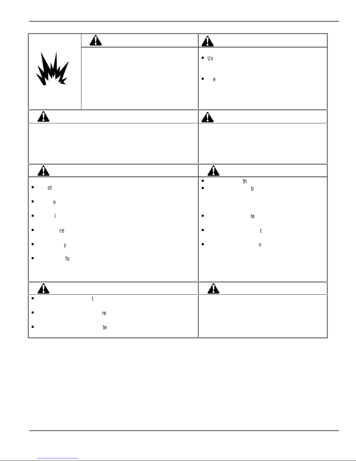
WARNING WARNING
Electric shock hazard:
This tool is not i nsul ated. When using this
unit near energized electrical lines, use
proper personal protective equipment.
Failure to observe this warning coul d
Result in severe injury or death.
WARNING WARNING
Skin injection hazard:
Do not use hands to check for oil l eaks.
High pressure oil easily punct ures ski n
causing serious injury, gangrene, or death.
If injured, seek m edi cal help immediately
to remove oil.
DANGER:
Indicates an imminently hazardous situation which, if not avoided, will result in
Death or serious injury.
WARNING:
Indicates a potentially hazardous situation which, if not avoided, will result in
Death or serious injury.
CAUTION:
Indicates a potential ly hazardous situat i on whi ch, if not avoided, may result in
Minor or moderate injury. CA UTION may also be used to alert against unsaf e
practices associated with events that could l ead t o personal injury.
Wear eye protection when operating
or servicing this tool.
Failure to wear eye protection coul d
result in serious eye injury from flying
debris or hydraulic oil.
Pinch points:
Keep hands away from the crimpi ng
head when crimping.
Failure to observe this warning coul d
Result In severe inj ury or death.
Doc No: ATS-638160200 Release Date: 12-06-07
Revision: A Revision Date: 12-06-07
UNCONTRO L L ED CO P Y Page 3 of 21
Page 4
CS 150 Battery Crim pi ng Tool
Do not use solvents or flammable liquids to cl ean
the crimping tool .
Solvents or flammable liquids could ignit e and
cause serious injury or property damage.
WARNING WARNING
WARNING WARNING
Do not dispose of the battery in a fire. It will vent fumes and may explode.
Failure to observe this warning coul d resul t i n severe i nj ury f rom harm f ul
fumes or burns from flyi ng debris
CAUTION CAUTION
Do not operate the tool wi thout the dies. Damage t o the ram or crimping
head can result.
Do not operate with t he cri m pi ng head open. D am age to the ram or
seals can result.
This tool is not desi gned for continuous use. After 100 crimpi ng cycl es,
allow the crimpi ng tool to cool down for 15 minutes.
Do not place the tool in a vise. The crimping tool is designed for hand-held
Operation only.
This tool may be used in dam p or wet environments; however, we
recommend air-drying the tool bef ore use if it becomes soaked.
Use this tool f or t he m anuf acturer’s intended purpose only.
Failure to observe these precautions m ay result in injury or property damage.
An incomplete crim p can cause a f i re.
Use proper die, connector, and cable combi nations.
Improper combinations can resul t i n an
incomplete crimp.
The relief valve will sound to indicate a completed
crimp. If you do not hear t he sound of t he rel i ef valve,
the crimp is not com pl et e.
Failure to observe these warnings could resul t in severe
injury or death.
Inspect tool and di es bef ore use. Replace any worn or
damaged parts. A damaged or improperly assembl ed
tool can break and strike someone nearby.
Failure to observe this warning coul d resul t in severe
injury or death.
Do not allow anything to contact the battery’s terminals.
Do not immerse the bat tery in liquid. Liqui d m ay
create a short circuit and damage t he bat t e ry.
If the batt ery is i m mersed, contact your service
center for proper handling.
Do not place the batt ery i nt o a pocket, tool pouch, or
tool box with conduct ive objects.
Conductive objects m ay creat e a short circuit and
damage the battery.
Do not place a battery on moist ground or grass.
Moisture may create a short ci rcuit and damage the
battery.
Failure to observe these precautions m ay resul t i n injury
or property damage.
CAUTION CAUTION
Do not store the batt ery at m ore t han 60 °C (140 °F). Dam age t o the
battery can result.
Do not use another manufact urer’s charger. Other manufacturers’
chargers may overcharge and damage the battery.
Do not attempt to open the battery. It contains no user-serviceable parts.
Failure to observe these precautions m ay result in injury or property damage.
For Service, Contact Your Local Molex Sales Office
Doc No: ATS-638160200 Release Date: 12-06-07
Revision: A Revision Date: 12-06-07
Do not perform any service or maintenance other than as
described in this manual .
Failure to observe this precauti on m ay resul t i n i njury
and property damage.
Molex Application Tooling Group
2200 Wellington Court
Lisle, Illinois 60532
Tel: 630-969-4550
Fax: 630-505-0049
UNCONTRO L L ED CO P Y Page 4 of 21
Page 5

CS 150 Battery Crim pi ng Tool
2.1 Description
2.2 Features
2.3 Technical Specifications
2.4 Delivery Check
2.5 Tools
Section 2
General Description
Doc No: ATS-638160200 Release Date: 12-06-07
Revision: A Revision Date: 12-06-07
UNCONTRO L L ED CO P Y Page 5 of 21
Page 6
CS 150 Battery Crim pi ng Tool
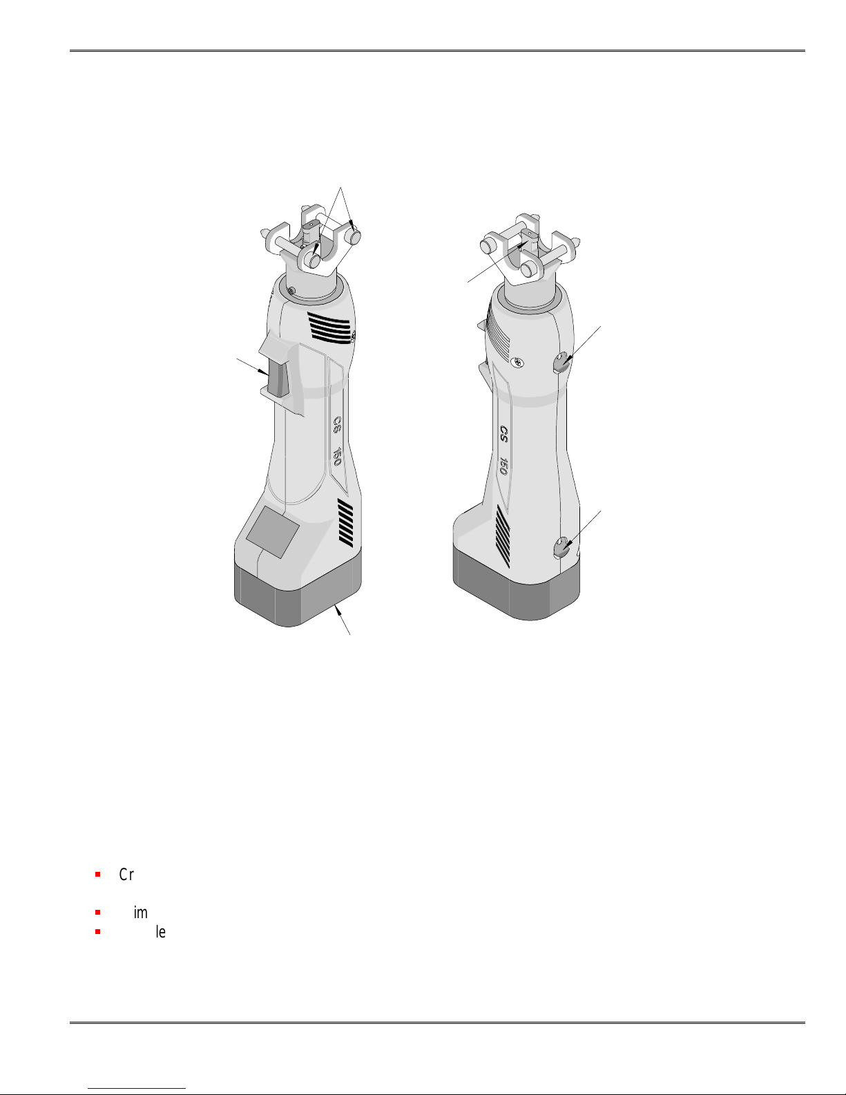
Figure 2
General Description
2
Principal M echani cal Parts of the 63816-0200 (Battery charger not shown)
TRIGGER
2.1 Description
The Molex Battery Crimpi ng Tool i s designed t o crimp 8 to 4/0 AWG insulated and uninsulat ed terminals and
splices. This tool has an automatic retractabl e system which returns the crimpi ng adapter along with the
crimping dies to the start i ng posit i on when the maximum force is reached. It i s equipped wi th a special brake
that will stop the forward motion of t he crimping dies when the trigger is released. The crimping head can be
rotated 360o for better access in diff i cul t worki ng sit uations.
2.2 Features
Crimps a wide range of products with i nt erchangeable tool heads and tool kits, which reduce the overall cost
and provide production flexibility.
Crimping heads and dies are easily and quickly interchanged to reduce production down t i m e.
Complete portable system that allo ws t ool to be moved and stored easily.
LOCKING
PINS (2 )
CRIMPING
HEAD
ADAPTER
RECHARGEABLE
(NiCad 9.6V) BATTERY
RETRACT
SLIDE
UNLOCKING
SWITCH
-1
Doc No: ATS-638160200 Release Date: 12-06-07
Revision: A Revision Date: 12-06-07
UNCONTRO L L ED CO P Y Page 6 of 21
Page 7

CS 150 Battery Crim pi ng Tool
2.3 Technical Specification
Dimensions
(with battery)
Length 292.1mm (11.50”)
Width 76.2mm (3.00“)
Depth 50.8mm (2.00“)
Unpacked Weight 1.5kg (3.31lbs)
Production Rate
250 cycles per hour maximum, dependi ng on operat or sk ill and t ool kit inst alled.
Battery
Voltage 9.6V
Capacity 1.3 Ah
Charging Time: Approximately 40 Minut es, about 15 m i nutes with fast-charger
Crimps/battery-charge 150 at 10mm
2
Operating Parameters
Maximum Force 15kN (1.7 tons)
Cycle Time 2.0 seconds
Stroke Length 9.0mm (.354”)
Ambient Temperat ure -20oC to +40oC
Sound Level 75dB (A) in a distance of 1. 0m
Vibrations <2.5m/s
2
2.4 Delivery Check
Carefully remove the CS 150 B attery Crimping Tool from i t s shippi ng cont ainer and determine that the
following item s are included i n the package.
á
CS 150 Battery Cri m ping Tool wi th battery
á
Battery Charger
á
Carrying Case
á
63816-0200 Instruction Manual
Doc No: ATS-638160200 Release Date: 12-06-07
Revision: A Revision Date: 12-06-07
UNCONTRO L L ED CO P Y Page 7 of 21
Page 8

CS 150 Battery Crim pi ng Tool
3.1. Setup
3.2. Operation
3.3. Installation of Tool Kits
Section 3
Set-Up and Adjustments
Doc No: ATS-638160200 Release Date: 12-06-07
Revision: A Revision Date: 12-06-07
UNCONTRO L L ED CO P Y Page 8 of 21
Page 9

CS 150 Battery Crim pi ng Tool
3.1 Set-Up
Before starting any work on electri cal appl i cat ions m ake sure there are no
live cables or parts in the immediate area of the user.
CRIMPING
HEAD WITH
TOOLING
WARNING
Remove the battery from the crimping tool bef ore
installing and removing dies in t he crimp head.
1. Select the appropriat e crim ping head wi th the proper tooling kit
inserted for the applicat i on needed.
2. Remove the locking pins (2) from the adapt er pl at e on the crimping
tool.
3. Place the crimping head into the adapter and push down until it
engages into the slot of t he adapter.
4. Replace the locking pins (2) making sure the crimping head is secure.
The locking pins can be inserted from either side of the adapter plate.
See Figure 3-1.
WARNING
Electric shock hazard:
This tool is not insulated. When using this
unit near energized electrical lines, use
proper personal protective equipment.
Failure to observe this warning coul d
Result in severe injury or death.
LOCKING
LATCH
ADAPTER
PLATES
LOCKING
PINS (2 )
WITH LOCATOR
CRIMPING
HEAD
ADAPTER
CRIMPING
TOOL
RETRACT
SLIDE
Figure 3-1
WARNING
Wear eye protection when operating
or servicing this tool.
Failure to wear eye protection coul d
result in serious eye injury f rom flying
debris or hydraulic oil.
3.2 Operation
1. Insert the proper termi nal or connector i nto the tooling nest and push on the
trigger in the handle just enough so t he di es contact the terminal or connector
securely. Release the trigger. This all ows t he operator to make adjustments
to the connector before the final terminati on.
2. Insert the wire or cable into the terminal. Push on the wire or cable to assure it is fu ll y seat ed in t he
terminal.
3. Hold the trigger down again unti l t he crim pi ng tool achieves pressure relief, which is accompanied by an
audible “pop”.
TERMINAL
AND WIRE
IN PLACE
HOLD
TRIGGER
DOWN
Figure 3-2
Doc No: ATS-638160200 Release Date: 12-06-07
Revision: A Revision Date: 12-06-07
UNCONTRO L L ED CO P Y Page 9 of 21
Page 10

CS 150 Battery Crim pi ng Tool
The crimping operation can be i nt errupted at any time during the cycle by releasing the trigger.
4. The crimping cycle is compl ete when the dies are complet el y closed and the maximum crim pi ng f orce i s
reached. The dies will automatically release and will go back to their original position.
Note: In case of a n e rro r or emergency, th e ram can be retract e d be fore the crim p i n g cycl e is complete . To do
this push the retractor slide t owards t he bat tery. See Figure 3-1.
Warning: DO NOT crimp copper and AI conducting material together or special connecting material. If
a different conducting m at eri al has t o be crim ped, pl ease contact t he m anufacturer.
WARNING
An incomplete crimp can cause a f i re.
Use proper die, connector, and cable combinat i ons. I m proper combinat i ons can result i n an i ncom pl et e crim p.
The relief valve will sound to indicate a completed crimp. If you do not hear the sound of the relief valve,
the crimp is not compl et e.
Failure to observe these warnings could result i n severe inj ury or death.
3.3 Preventive Instructions
WARNING
Do not dispose of the battery in a fire. It will vent f umes and may explode.
Failure to observe this warning could result i n severe inj ury f rom harm ful fumes or burns from flying debris.
WARNING
Inspect tool and dies before use. Repl ace any worn or damaged part s. A dam aged or i m properl y
assembled tool can break and strike someone nearby.
Failure to observe this warning could result i n severe inj ury or deat h.
CAUTION
Do not operate the tool without the dies. Damage t o the ram or crimping head can result.
Do not operate with t he crimpi ng head open. Damage to the ram or seals can result.
This tool is not designed for continuous use. After 100 crimping cycles, al l ow the crimping tool t o
cool down for 15 minutes.
Do not place the tool in a vise. The crimpi ng tool is designed for hand-held operation only.
This tool may be used in damp or wet environment s; however, we recomm end ai r-drying the tool
before use if it becomes soaked.
Use this tool for t he m anuf act urer’s intended purpose only.
Failure to observe these precautions may result in i nj ury or propert y damage.
Doc No: ATS-638160200 Release Date: 12-06-07
Revision: A Revision Date: 12-06-07
UNCONTRO L L ED CO P Y Page 10 of 21
Page 11

CS 150 Battery Crim pi ng Tool
CAUTION
Do not allow anything to cont act the battery’s term i n a l s.
Do not immerse the battery in liquid. Liquid m ay create a short ci rcuit and dam age the battery.
If the battery is immersed, contact your service center for proper handl i ng.
Do not place the battery into a pocket, tool pouch, or tool box with conductive objects.
Conductive objects may create a short circuit and damage t he battery.
Do not place a battery on moist ground or grass. M oist ure m ay create a short circuit and damage
the battery.
Failure to observe these precautions may result in i nj ury or propert y damage.
Avoid dropping this tool. Extreme shock may damage the internal mechanism and result i n m al f unct i on of the
tool.
Doc No: ATS-638160200 Release Date: 12-06-07
Revision: A Revision Date: 12-06-07
UNCONTRO L L ED CO P Y Page 11 of 21
Page 12

CS 150 Battery Crim pi ng Tool
Terminal Specifications and Crimping Operation
4.1 Scope
4.2 Terminal Specifications Chart
Section 4
Doc No: ATS-638160200 Release Date: 12-06-07
Revision: A Revision Date: 12-06-07
UNCONTRO L L ED CO P Y Page 12 of 21
Page 13

CS 150 Battery Crim pi ng Tool
4.1 SCOPE
This tool is designed to crimp various Molex term i nal s and splices using our offering of crimping heads.
Testing
Mechanical
The tensile test, or pull test, is a means of evaluating t he m echanical properties of the crimped connections.
The following charts show the UL specifi cat i ons f or various wire sizes. The t ensil e st rength is shown in
pounds, which indicates the mini m um acceptabl e f orce t o break or separate the terminal from the conductor.
Wire Size (AWG) Tooling Color Code *UL – 486A **UL – 486C ***MIL-T-7928
22 8 8
20 13 10
18 20 10
16 30 15
14 50 25
12 70 35
10 80 40
8 Red 90 45 225
6 Blue 100 50 300
4 Yellow 140 - 400
2 Red 180 - 550
1 Blue 200 - 650
1/0 Blue 250 - 700
2/0 Yellow 300 - 750
3/0 Red 350 - 825
4/0 Blue 450 - 875
*UL – 486A – Terminals (Copper Conductors Only)
**UL – 486C – Butt Sli ces and Paral le l Slices (Over 6 AWG use 486A values)
***MIL-T-7928 - Military Approved Terminals only as listed
4.2 Crimping Terminals
Specifications and Inst ruct i ons f or crim ping are i ncl uded with the individual Bat tery Powered Crimp Tool
Heads.
Doc No: ATS-638160200 Release Date: 12-06-07
Revision: A Revision Date: 12-06-07
UNCONTRO L L ED CO P Y Page 13 of 21
Page 14

CS 150 Battery Crim pi ng Tool
5.1 Periodic Cleaning
5.2 Storage
5.3 Battery and Charging Unit
5.4 Disposal
5.5 Warranty
Section 5
Preventive Maintenance
Doc No: ATS-638160200 Release Date: 12-06-07
Revision: A Revision Date: 12-06-07
UNCONTRO L L ED CO P Y Page 14 of 21
Page 15

CS 150 Battery Crim pi ng Tool
5.1 Periodic Cleaning
Always clean tool after use and keep moving part s clear of di rt and debris.
This tool is basically maintenance free, onl y the bol t joints at the crimping head have t o be oil ed regul arl y.
Before use:
1. Inspect dies fo r wear or dam age such as cracks, gouges, or chips.
2. Inspect the tool f or dam age or l eaks. I f damage is detected, return the tool to a Molex representat i ve f or
inspection.
After use:
1. Wipe all tool surfaces clean with a dam p cl ot h and m i l d det ergent. Excessive dirt and grit can contribute
to the premature wear of t he tool’s internal mechanical parts. If this tool becomes dirty with excessive
debris it may jam and become damaged during operat i on.
3. Fully retract the ram. Place the tool in the carrying case. S tore in a cool, dry place.
4. Charge the battery.
WARNING WARNING
Skin injection hazard:
Do not use hands to check for oil l eaks.
High pressure oil easily punct ures ski n
causing serious injury, gangrene, or death.
Monthly:
1. Thoroughly clean all surfaces.
A routine should be established to keep t he tool as free from dirt as possible.
If injured, seek m edi cal help immediately
to remove oil.
Do not use solvents or flammable liquids to
clean the crimping t ool .
Solvents or flammable liquids could ignite and
cause serious injury or property damage.
Doc No: ATS-638160200 Release Date: 12-06-07
Revision: A Revision Date: 12-06-07
UNCONTRO L L ED CO P Y Page 15 of 21
Page 16

CS 150 Battery Crim pi ng Tool
An example of a maint enance chart i s shown below. Copy and use thi s chart t o track the maintenance of
this crimping tool or use thi s as a tem pl at e to create you own schedule or use your company’s standard
chart, if applicable.
Preventive Maintenance Chart
CHECK SHEET MONTH
Week
1
2
3
4
Cleaning Daily After use
Lubrication (2) bolts in crimping head Use SAE 10W
Hydraulic oil
Daily
Use
YEAR _________
Days of the Week
MON TUE WED THU FRI SAT
SUN
Solution
Schedule should be adjusted up or down depending on usage. Molex recommends t hat a log of preventive
maintenance be kept with t he tool.
5.2 Storage
In order to protect t he t ool agai nst damages, this tool should be cleaned carefully aft er every use. I t should
then be placed into the carrying case along with the charging unit, crimp heads and the inst ruct ion m anual
and stored in a dry location.
5.3 Battery and Charging Unit
CAUTION WARNING
Do not store the batt ery at m ore t han 60 °C (140 °F). Damage t o t he
battery can result.
Do not use another manufact urer’s charger. Ot her m anuf act urers’
chargers may overcharge and damage the battery.
Do not attempt to open the battery. It contains no user-serviceable parts.
Failure to observe these precautions may result in injury or property damage.
CAUTION
Do not allow anyt hi ng t o contact the battery’s termi nals.
Do not immerse the bat tery in liquid. Liqui d m ay creat e a short ci rcui t and dam age the battery.
If the batt ery is i m mersed, contact your service center for proper handling.
Do not place the batt ery i nt o a pocket, tool pouch, or tool box w i t h conductive objects.
Conductive objects m ay creat e a short ci rcui t and dam age the battery.
Do not place a battery on moist ground or grass. Moisture may create a short circuit and damage the battery.
Failure to observe these precautions m ay result in injury or property damage.
Doc No: ATS-638160200 Release Date: 12-06-07
Revision: A Revision Date: 12-06-07
Do not dis p o s e o f th e b atte ry in a fir e . It will v e n t fumes
and may explode.
Failure to observe this warning coul d resul t in severe
injury from harmful fumes or burns from flying debris
UNCONTRO L L ED CO P Y Page 16 of 21
Page 17

CS 150 Battery Crim pi ng Tool
The charging unit is run with a nominal voltage of 110V and a frequency of 50-60Hz . New bat t eri es must be
charged before use. To remove the battery f rom t he crim pi ng t ool push down on t he bat tery lock and pull out.
See Figure 4-1. To charge the batt ery plug i n the charging unit into a power source and slide the bat t e ry
upside down into the charging unit. The norm al charging t i m e i s about 40 mi nutes. The charging level of the
battery cartridge can be checked by the right LED (m ul ticolor) of the charging unit .
Color Left LED (red) Right LED (multicolor)
Red Charging Unit is ready to operate. Battery def ect
Red
Flashing
Charging Unit is out of order.
New or unused battery’s
voltage capacity is insufficient.
Battery too hot or too cold. Remove the battery.
Safety components possibly defected.
Green --- Charging cycle stared.
Battery full y charged. Chargi ng uni t swit ches aut om at i call y
Green
Flashing
---
into a maintaining level.
Battery can stay in charge for an indefinite tim e wi t h out
being damaged.
Yellow --- Battery is at l east 90% charged. Charging can be t erm i nated.
--- ---
If the Right LE D does not l i ght up, the circuit of t he bat tery
is disconnected or the battery is incorrectly pol arized.
Notes:
1. If the standard capacity of t he battery is not achieved, it does not m ean t hat the battery is fault y. The full
capacity of the bat tery can be achieved after 3 charging/ di schargi ng cycl es.
2. If there is a noticeable decrease in speed of t he crim pi ng t ool t he battery should
be recharged.
Charge the battery at room temperature between 10oC-40oC (500F-104oF).
3. The battery should be charged before storing.
Cautions:
1. Charging a battery which has been used recently or in the sun or a long period
of time the ri ght LED might flash red, (Tem peratures greater than 65
In this case let the bat tery cool down and try again.
2. Charging the battery at l ow temperatures under 5oC (41oF) is not possible. The
battery temperature must be warmed up before st arting the battery cycl e again.
3. Do not expose the charging unit to rain or snow.
4. Do not charge the battery in or around explosive materials or gases.
5. Do not use any other (dry or car) battery with t he charging uni t or the crimping
tool.
6. Do not use the cord as a handle to carry the batt ery unit .
7. Do not pull the cord out of a wal l socket wi t h force.
8. Do not pull the plug of t he charging uni t until after t he battery has been charged.
9. Do not insert foreign object s into the ducts of the charging unit .
10. Do not disassemble the charging unit.
11. Do not place the battery in your pocket or a tool box, if there are conduct ive m at eri al s such as coins,
keys, tools or other metallic parts may cause injury or property damage.
o
C (149oF).
Figure 4-1
PUCH DOWN
ON SWITH
BATTERY
UNIT
Doc No: ATS-638160200 Release Date: 12-06-07
Revision: A Revision Date: 12-06-07
UNCONTRO L L ED CO P Y Page 17 of 21
Page 18

CS 150 Battery Crim pi ng Tool
5.4 Disposal
When this tool is no longer operating properly the different components of this tool will need to be disposed of
separately.
1. The hydraulic oil must be disposed of at a local drop-off recycling center.
ATTENTION
Disposal of Hydraulic fluid represents a danger t o ground-water. Uncontrolled draining of
or improper disposal is under penalty (environmental liabilit y law) t hru the Environmental
Protection Agency (EPA) guidelines.
2. The battery must be di sposed of accordi ng to the Rechargeable Battery Recycling Corporation
(RBRC) guidelines.
3. The remaining parts of thi s tool m ust be disposed of according to the domestic environmental
standards or the Environmental Protection Agency (EPA) guidelines.
4. Because of possible environmental damage, we recomm end di sposal of t he tool by a professional
company.
ATTENTION
Do not dispose of this tool in your residential or commercial waste,
as it would be hazardous to the environment.
5.5 Warranty
All tools are warranted t o be free of manufacturing def ect s f or a period of 30 days. Should such a defect
occur, we will repair or exchange the tool free of charge. This repair or exchange will not be applicable to
altered, misused, or damaged tools. This tool is designed for hand use only. A ny clam ping, fixturing, or use
of handle extensions voids this warranty. A fter one year Molex recommends the crimping t ool be returned to
a Molex representative for inspection. Only the heads of the crimping tool are perm i t ted to be changed by the
operator.
ATTENTION
Do not damage the seals of thi s tool .
If seals are damaged the warranty is inval id .
CAUTION: Mol ex crimp specif i cat ions are vali d onl y when used wit h M ole x term i nal s and t ool i ng.
Doc No: ATS-638160200 Release Date: 12-06-07
Revision: A Revision Date: 12-06-07
UNCONTRO L L ED CO P Y Page 18 of 21
Page 19

CS 150 Battery Crim pi ng Tool
6.1. Parts List and Assembly Drawing
6.2. Troubleshooting
Section 6
Doc No: ATS-638160200 Release Date: 12-06-07
Revision: A Revision Date: 12-06-07
UNCONTRO L L ED CO P Y Page 19 of 21
Page 20

CS 150 Battery Crim pi ng Tool
6.1 Parts List and Assembly Drawings
Item Order No Description Quantity
1 63816-0200 Battery Crimp Tool CS 150 1
2 63816-0201 Battery Powered Tool Head (without tool i ng) CSE30 1
3 63816-0202 Battery Unit CS 150 1
2
1
3
Figure 6-1
Doc No: ATS-638160200 Release Date: 12-06-07
Revision: A Revision Date: 12-06-07
UNCONTRO L L ED CO P Y Page 20 of 21
Page 21

CS 150 Battery Crim pi ng Tool
6.2 Troubleshooting
Make sure the battery is charged before toubl eshooti ng this tool.
Symptom
Tool is
inoperative.
Dies stop
during operation.
Cause Solution
Dirt, contaminants, etc.,
in ram area of tool.
Battery unit cont act s corroded.
Battery unit cont act s damaged. Reform the contacts.
Tool parts worn or damaged. Contact a Molex representative.
Oil level is low. Contact a Molex representati ve.
Air in Hydrau l ic system.
Clean the crimping tool.
Clean contacts with pencil eraser or
contact cleaner
Pull the trigger and hol d t he retract slide
simultaneously for about 10 seconds.
LED glows for
20 seconds.
Crimping Tool
loses oil.
Americas Headquar ters
Lisle, Illinois 60532 U.S.A.
1-800-78MOLEX
amerinfo@molex.com
Battery charge is low. Charge or replace battery unit.
Damage to the internal seal. Contact a Mol ex representative
Far East North Hea dquarters
Yamato, K anagawa, J apan
81-462-65-2324
feninfo@molex.com
Visit our Web site at http://www.molex.com
Far East South He adqua rters
Jurong, Singapore
65-6-268-6868
fesinfo@molex.com
European Headquarters
Munich, Germany
49-89-413092-0
eurinfo@molex.com
Corporate Headqua rters
2222 Wellington Ct.
Lisle, I L 60532 U.S.A.
630-969-4550
Fax: 630-969-1352
Doc No: ATS-638160200 Release Date: 12-06-07
Revision: A Revision Date: 12-06-07
UNCONTRO L L ED CO P Y Page 21 of 21
 Loading...