

Page 1
Brad® • i • IP67 IO-Link Digital Hubs
User’s Manual
IO-Link M12 Digital Hubs
Brad® from Molex
Version 1.2
October 04th, 2018
Page 2
Brad® • ii • IP67 IO-Link Digital Hubs
Revision History
Date
Authors
Changes
Revision
February 13th 2017
SS
First release
1.0
March 22nd 2017
JCD
Ratings update
1.1
October 04th 2017
OL
Adding TEDIO-8B4P-808-1
1.2
Although every effort has been made to ensure the accuracy of this document, all information is subject to
change without notice. Molex takes no liability for any errors in this document or for direct, indirect, or
consequential damage resulting from the use of this manual.
Page 3

Brad® • iii • IP67 IO-Link Digital Hubs
STATEMENT OF LIMITED WARRANTY
Brad® from Molex, manufacturer of IP67 products, warrants to Buyer that products, except software,
manufactured by Brad will be free from defects in material and workmanship. Brad obligation under this
warranty will be limited to repairing or replacing the defective parts within one year of the date of purchasing.
Products may be returned by Buyer only after permission has been obtained from Brad. Buyer will prepay all
freight charges to return any products to the repair facility designated by Brad.
Brad® further warrants that any software supplied as part of a product sale, except obsolete products, will be
free from non-conformances with Brad published specifications for a period of 90 days from the time of
delivery. While Brad endeavors to improve the features and performance of software associated with its
products, no effort on the part of Brad to investigate, improve or modify product firmware at the request of a
customer will obligate Brad in any way.
For the convenience of existing customers, Brad continues to supply certain products that are classified as
obsolete. No warranty on the software features of these products is stated or implied and Brad specifically is
not obligated to improve the design of these products in any way. Information about the status of any product
is available upon request and customers are advised to inquire about the status of older products prior to
making a purchase.
This limited warranty does not cover losses or damages which occur in shipment to or from Buyer or due to
improper installation, maintenance, misuse, neglect or any cause other than ordinary commercial or industrial
applications. In particular, Brad makes no warranties whatsoever with respect to implied warranties of
merchantability or fitness for any particular purpose. All such warranties are hereby expressly disclaimed. No
oral or written information or advice given by Brad or Brad's representative shall create a warranty or in any
way increase the scope of this warranty. This limited warranty is in lieu of all other warranties whether oral or
written, expressed or implied. Brad’s liability shall not exceed the price of the individual units, which are the
basis of the claim. In no event shall Brad be liable for any loss of profits, loss of use of facilities or device, or
other indirect, incidental or consequential damages.
Although every effort has been made to ensure the accuracy of this document, all information is subject to
change without any notice. Brad takes no liability for any errors in this document or for direct, indirect, or
consequential damage resulting from the use of this manual.
The examples and diagrams in this manual are included solely for illustrative purposes. Because of the many
variables and requirements associated with any particular installation, Brad cannot assume responsibility or
liability for actual use based on the examples and diagrams.
COPYRIGHTS and TRADEMARKS
Reproduction of the contents of this manual, in whole or in part, without written permission of Brad is
prohibited.
Mini-Change®, Ultra-Lock™, Brad are all registered trademarks of Molex, Inc.
All other products or trademarks are the property of their respective owners.
Page 4

Brad® • iv • IP67 IO-Link Digital Hubs
Table of contents
1. General Safety Instructions ................................................................ 5
General information ................................................................................................. 5
Personnel qualifications .......................................................................................... 5
Preventive messages .............................................................................................. 5
Usage compliance ................................................................................................... 5
Device installation and set-up ................................................................................. 6
Device operation ..................................................................................................... 7
Preventive and corrective maintenance .................................................................. 7
2. System description .............................................................................. 8
Introduction .............................................................................................................. 8
Overview ................................................................................................................. 9
Physical & System description .............................................................................. 10
IO-Link & Power supply connector ........................................................................ 11
IO Ports ................................................................................................................. 13
Functional Earth Connection ................................................................................. 15
3. Technical Data ................................................................................... 16
Dimensions ............................................................................................................ 16
Mechanical and Environmental Data .................................................................... 17
IO-Link & Power Supply Electrical Data ................................................................ 17
I/O Connector Electrical Data ................................................................................ 18
4. Input /Output Process Data ............................................................... 19
Input Process Data ................................................................................................ 19
Output Process Data ............................................................................................. 20
5. Identification & Device Parameters .................................................. 21
IODD file ................................................................................................................ 21
Direct parameters Page 1 ..................................................................................... 22
ISDU* Identification Parameters ............................................................................ 23
ISDU Device Parameters ...................................................................................... 24
ISDU Error type ..................................................................................................... 28
6. Product support ................................................................................. 29
Technical Support ................................................................................................. 29
Web Site ................................................................................................................ 29
Page 5

Brad® • 5 • IP67 IO-Link Digital Hubs
1. General Safety Instructions
General information
The current documentation is intended for persons technically qualified to install, use and service the products
described herein. It contains the necessary information for proper use of the products. However, for advanced
use of our products, please contact your nearest dealer for additional information.
The content of this documentation is not binding and cannot extend or limit warranties.
Personnel qualifications
Only qualified persons are authorized to install, use and service the products. Use by unqualified persons or
failure to follow the safety instructions of this document, the manuals and/or those affixed to the devices, can
result in irremediable harm or damage to persons and equipment. The following personnel are deemed to be
qualified persons for:
• Equipment operation: Personnel who operates the machines and/or processes connected to the Brad
products. Brad product must be used by persons who have received training and have been informed
of the major risks involved in working in an industrial environment.
• Preventive and corrective maintenance: Persons who modify Brad products hardware and software
configuration and install the product updates supplied by the manufacturer. These persons must:
o be trained in Brad products and operation and
o have the experience and technical knowledge required to be aware of the risks (electrical
hazards in particular) involved in their job and the ways of reducing these risks for
themselves, third parties and the equipment being used.
Preventive messages
Preventive messages are designed to identify the particular risks likely to affect personnel and/or hardware.
Different message types, both in the documentation and on the products, indicate different degrees of risk:
Danger messages indicate immediate hazards that could result in death or serious injury if not averted.
Warning messages indicate situations that could result in death, serious injury or material damage.
Caution messages indicate potentially dangerous situations that could cause bodily harm or material damage.
Usage compliance
The products described in the current documentation comply with currently applicable European
Directives (EC marking). However, they can only operate correctly with the applications for which they were
intended as described in the documentation, and with approved products.
Page 6

Brad® • 6 • IP67 IO-Link Digital Hubs
As a general rule, if all the handling, transportation, and storage recommendations and installation, operation
and maintenance instructions are followed, the products will operate correctly without risk for personnel or
hardware.
Device installation and set-up
It is important to follow the rules below when installing and setting up the Brad product. If system installation
includes products more than thirty meters away from each other, the basic cabling rules must be closely
followed.
• Strict compliance with the safety instructions provided in this documentation or on the equipment to be
installed and implemented, is absolutely essential.
• Make sure that the installation is carried out in compliance with regulations of the user country,
• Install the equipment in a suitable environment. As a closed equipment, the Brad product may be
installed in two ways:
o In a casing (cabinet, chest) or,
o Directly without any additional protection, if the associated systems (power supply, cables,
sensors, etc.) already carry a protection index equivalent to IP67 or higher.
Always connect the Brad product to the functional earth (FE) in compliance with existing standards.
• LV (Low Voltage) circuits must have a functional earth connection to ensure dangerous voltage
detection.
• Check that the power voltages are within the tolerance ranges defined in the technical specifications
for the devices.
• Always ensure that power restoration (immediate, hot or cold) will not create a hazard for personnel or
equipment.
• Ensure that emergency stop devices remain effective in any equipment operation mode, even when
abnormal (for example, in the event of a wire cut). Resetting these devices should not result in
uncontrolled or undefined restarts.
• Position the signal cables so that the automation functions will not be disrupted by any capacitive,
inductive or electromagnetic influences, etc.
• Install the automation devices and their controlling devices so that they are protected against any
adverse incident.
• Adequate safety precautions must be applied to inputs and outputs to prevent the lack of signals from
causing undefined states in the automation devices.
Page 7

Brad® • 7 • IP67 IO-Link Digital Hubs
Device operation
Because Brad product devices are components of a control system, the safety of the entire automated system,
including that of the installation and the application, cannot be dealt with in this document. For further
information, see IEC 61131-2, describing risk reduction measures for PLC users.
See the documentation of the specific products involved for more information on operation safety.
Preventive and corrective maintenance
Servicing
• When replacing parts or components, only use factory approved parts.
• In all cases, before servicing a Brad product, disconnect the power supply from the device (unplug the
power cord or open the power cut-out device) or the M12 IO link cable.
• Before servicing an onsite mechanical Brad product, disconnect its power supply and mechanically
lock the moving parts.
• On positive logic outputs or negative logic inputs, take all the necessary precautions to prevent any
disconnected wires from coming into contact with the mechanical ground (risk of unwanted
commands).
Product end-of-life
Contact your local dealer for information on how to dispose of used products in compliance with current
regulations.
Page 8

Brad® • 8 • IP67 IO-Link Digital Hubs
2. System description
Introduction
Brad® IO-Link M12 Digital Hubs is a reliable solution for connecting
any compliant IO-Link master and digital sensors or actuators in harsh
duty environments. Contained in an IP67 rated housing, the hubs can
be machine mounted and are able to withstand areas where liquids,
dust or vibration may be present. This makes them ideally suited for
many applications including material handling and automated
assembly.
IO-Link digital hubs includes advanced diagnostic features. Each hub
embeds visible LEDs to provide maintenance personnel the ability to
easily determine power, I/O and IO-Link status.
IO-Link digital hubs main features:
• Digital hub is housed in an IP67 rated enclosure that when
properly installed – according to IEC 60529 – provides protection against the ingress of dust and
temporary water immersion.
• 1x IO-Link connector + 16 digital I/O channels
• Compliance with IO-Link Interface and System Specification v1.1.2
• Digital input and output short circuit protection
• Declarations
o CE according to EMC directive
• Certifications:
o c-UL-us
o FCC Part 15 Emissions; Class A
• Compliant with
o RoHS and RoHS China
o REACH
o CSA C22.2
Page 9
Brad® • 9 • IP67 IO-Link Digital Hubs
Overview
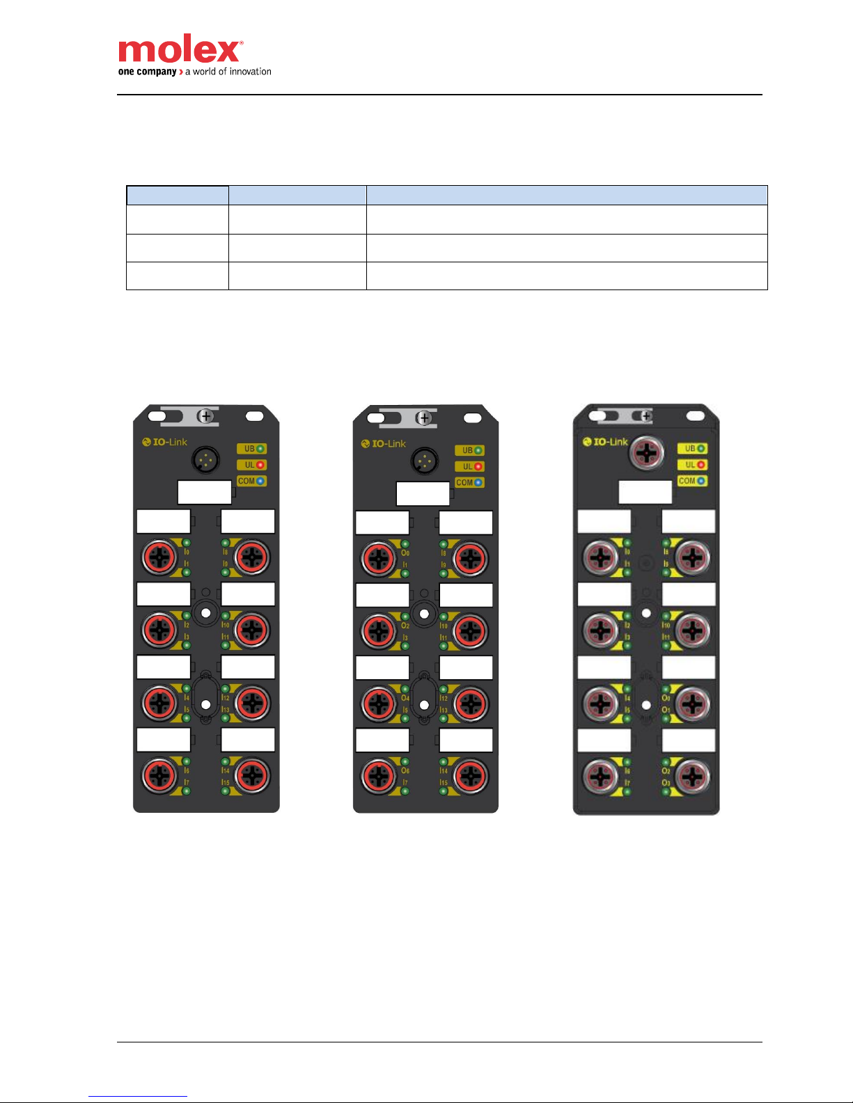
The IO-Link digital hubs are available in 3 versions.
SAP No
Material No
Description
112103-5000
TEDIO-8D0P-808
IO-Link Digital Hub 16x inputs
112103-5001
TEDIO-8B4P-808
IO-Link Digital Hub 12x inputs + 4x outputs
112103-5002
TEDIO-8B4P-808-1
IO-Link Digital Hub 12x inputs + 4x outputs grounded
TEDIO-8D0P-808
TEDIO-8B4P-808
TEDIO-8B4P-808-1
Page 10

Brad® • 10 • IP67 IO-Link Digital Hubs
Physical & System description
IO-Link connector
Mounting screw (Functional Earth - FE)
I/O Connectors
Plastic label
Port 0
Port 1
Port 2
Port 3
Port 4
Port 5
Port 6
Port 7
Shield Plate
Mounting hole
3 LEDs indicators
2 Mounting holes
Page 11

Brad® • 11 • IP67 IO-Link Digital Hubs
IO-Link & Power supply connector
Pinout and Orientation
The digital hubs have an IO-Link connector that provides the IO-Link communication and the power for the
digital sensors and actuators.
Pin
5 pins Power Connector - Description
1
L+: 24VDC - Input and hub power supply
2
UL+: 24VDC - Output power supply
Optional for TEDIO-8B4P-808 except if outputs are used.
Optional for TEDIO-8B4P-808 / TEDIO-8D0P-808 except if additional Sensor Power
(software configuration dependent) is required.
3
Common L-/UL- (0V)
4
C/Q: IO-Link data transmission cable
5
Shell - FE (Functional Earth)
LEDs 6
Bi-color red/green LED indicator for input & hub power supply L
7
Bi-color red/green LED indicator for output power supply UL (or Sensor Power)
8
Blue LED indicator for IO-Link communication
The IO-Link connector is oriented such as the IO-Link cable leaves the hub on the top (see picture below).
Note
The IO-Link digital hubs can be connected to the IO-Link master via 3, 4 or 5-wire
cables with a maximum length of 20 m.
6 7 8
5
Page 12

Brad® • 12 • IP67 IO-Link Digital Hubs
LEDs indicators
LEDs
Color State
State & Power supply voltages
UL
Fixed Green
Voltage present (18 - 30V)
Fixed Red
Voltage between 8V < UL < 18V
Voltage over 30V
Voltage between 0V < UL < 18V (if UL powers the sensors)
Overload (3.5A) or short circuit
Off
Voltage not present or below 8V
UB
Fixed Green
Voltage present (18 - 30V)
Fixed Red
Voltage between 9.5V < L < 18V
Voltage over > 30V
Overload (1.6A) or short circuit
Off
Voltage not present or below 9.5V
COM
Fixed Blue
Operate mode
Blinking Blue
Pre-operate mode
Off
No IO-Link communication
IO-Link Master power supply
The Molex IO-Link IP67 master modules (TCIEP-888P-D1U for PROFINET and TCIEI-888P-DYU / TCIEI888P-D1U for EtherNet/IP) provide 1.6A on Pin1 (L) of the IO-Link Hub connector. It means that you can
cover the maximum draw current in total (800mA).
Note
In case of overvoltage on L, all energized outputs will be shutdown
If L drops below 18V but UL remains, all energized outputs will be shutdown.
Note
Digital sensor/actuator cable are made of AWG22 wires (0.34 mm²). Take in account
the voltage drop across the connecting cable when preparing your cabling.
In case of maximal current consumption, 4A may flow through pin 3. To reduce the
voltage drop, contact Molex for cordsets with larger wire gauge.
Page 13

Brad® • 13 • IP67 IO-Link Digital Hubs
IO Ports
The digital hubs support up to 8 I/O ports offering 3 different types of fixed I/O configuration
• Input only
• Input / Output
• Dual output
Input only
Pin
I/O Connector - Description
Powered by
1
+24VDC
L or UL
2
Digital Input (DI) – Odd number
3
0V
4
Digital Input (DI) – Even number
5
Not connected
6
FE (Functional Earth)
LEDs
7
Bi-color red/green LED for even channel indicator – Pin4
8
Bi-color red/green LED for odd channel indicator – Pin2
Input / Output
Pin
I/O Connector - Description
Powered by
1
+24VDC
L or UL
2
Digital Input (DI) – Odd number
3 0V
4
Digital Output (DO) – Even number
UL
5
Not connected
6
FE (Functional Earth)
LEDs
7
Bi-color red/green LED for even channel indicator – Pin4
8
Bi-color red/green LED for odd channel indicator – Pin2
7 6 8
Page 14

Brad® • 14 • IP67 IO-Link Digital Hubs
Dual Output
Pin
I/O Connector - Description
Powered by
1
N/C
2
Digital Output (DO) – Odd number
UL
3
0V 4
Digital Output (DO) – Even number
UL 5 Not connected
6 FE (Functional Earth)
LEDs
7
Bi-color red/green LED for even channel indicator – Pin4
8 Bi-color red/green LED for odd channel indicator – Pin2
Note
M12 accessories (cordsets, plugs …) connected to the hub I/O and network connectors
shall be screwed with a torque of 2.0 Nm to ensure a correct sealing to achieve IP67
rating.
The I/O ports are oriented as follows:
7
8
Page 15

Brad® • 15 • IP67 IO-Link Digital Hubs
LEDs indicators
The table below shows the LEDs meanings and the I/O state
LEDs
Color State
I/O State
Ix
Fixed Green
DI is set to 1
Fixed Red
When Pin1 (L+) is shorted to ground
When overload detected on Pin 1
When L > 32V
Off
DI is set to 0
Color State
I/O State
Ox
Fixed Green
DO is energized
Fixed Red
DO: when energized and shorted to ground
DO: when not energized and shorted to 24V
DO: when overload detected
DO: when energized and UL is over voltage (UL > 30V)
DO: when energized and UL is under voltage (0V < UL < 18V)
Off
DO is not energized
DI: Digital input on Pin2/Pin4
DO: Digital output on Pin2/Pin4
Functional Earth Connection
The functional earth (FE) shall always be connected to ground to ensure proper operation of the hub.
Functional Earth (FE)
Page 16

Brad® • 16 • IP67 IO-Link Digital Hubs
3. Technical Data
Dimensions
All dimensions are in millimeters.
Page 17

Brad® • 17 • IP67 IO-Link Digital Hubs
Mechanical and Environmental Data
Mechanical
Housing dimensions
152 x 54 x 29.6 mm (5.98” x 2.12” x 1.16”)
Product weight
260 g
Housing material
PBT VALOX 420 SEO Black 7701
Mounting holes
2 oblong holes on top and 2 circular holes suitable for M4 screws
Ground stud
Yes (allows the continuity of the ground when the hub is mounted on the
chassis machine)
Operating temperature
0°C to +70°C
Storage temperature
-40°C to +90°C
Shock resistance
Operating: 15g, 11ms, 3 axis
Non-operating: 50g, 6ms, 3 axis
Electro-magnetic compatibility
EN 61000-6-2 / EN 61000-6-4
Relative humidity
5% to 95 %, non-condensing
Protection Class
IP67*1
Operating altitude
0 to 2000m
Overvoltage category
II or less
Pollution degree
2 or less
Approval
CE (according IEC 61131-2), cULus
Environmental
RoHS / RoHS China / REACH
*1 Only when all necessary waterproof connectors and caps have been installed.
IO-Link & Power Supply Electrical Data
Hub versions
TEDIO-8D0P-808
TEDIO-8B4P-808
TEDIO-8B4P-808-1
IO-Link connector & port type
M12, 4-pin, Male, A-Coded - Port class A
Protocol
Compliant with IO-Link specifications v1.1
Transmission mode
COM3
Minimum cycle time
1ms
Hub Logic & Input power (L)
24VDC (Allowable voltage range: 18 to 30VDC)
(Reverse polarity protected)
Warning, a voltage over 32VDC may destroy the product
Logic Operating current (L)
40mA
Max current supported (L)
0.8A
Output power (UL)
24VDC (Allowable voltage range: 18 to 30VDC)
(Reverse polarity protected)
Warning, a voltage over 30VDC may destroy the product
Operating current (UL)
10mA (without load)
Max current supported (UL)
2.8A
Functional Earth
1 screw terminal
Warning!
For compliance with UL mark, the power supply used with this product shall fulfill the
requirements for Safety Extra Low Voltage (SELV) and Limited Energy to IEC/EN/UL
61010-2-201.
Page 18

Brad® • 18 • IP67 IO-Link Digital Hubs
Note
L and UL are both returning via PIN3. The total current of L and UL shall not exceed 4A
based on the limitations of M12 connector specifications.
I/O Connector Electrical Data
Hub versions
TEDIO-8D0P-808
TEDIO-8B4P-808
TEDIO-8B4P-808-1
I/O connector
M12, 5-pin, female, A-Coded
Maximum current per port on Pin 1
100mA
Max draw current per I/O connector
100mA (if input only - TEDIO-8D0P-808)
0.6 A (if input / output combined - TEDIO-8B4P-808)
1A(if 2 output combined - TEDIO-8B4P-808-1)
Max draw current in total
800mA (if input only - TEDIO-8D0P-808)
2.8 A (if input / output combined - TEDIO-8B4P-808)
2.8 A (if input / output combined - TEDIO-8B4P-808-1)
Sensors draw current from
L (optionally UL)
Channels
Pin 2
Pin 4
Digital Inputs
Configuration
16 channels
12 channels
Input type
PNP sinking only, compliant to IEC 61131-2 Type 3
On-state current (typical)
2.5 mA
Off-state current (max.)
1 mA
Input channel voltage (“1”)
11 V … 30 V
Input channel voltage (“0”)
-5 V … 5 V
Input filter
User configurable: 0, 1, 3 and 5ms (1ms by default)
Digital Outputs
Number of Channels
4 channels
Output type
PNP, current sourcing
Max output current (per channel)
0.5 A
Max output current (Total)
2 A at 25°C
Page 19

Brad® • 19 • IP67 IO-Link Digital Hubs
4. Input /Output Process Data
Input Process Data
TEDIO-8D0P-808 (16 inputs)
Name
Process Data In (3 bytes)
Bit
Byte
7 6 5 4 3 2 1
0
0
DI7
DI6
DI5
DI4
DI3
DI2
DI1
DI0 1 DI15
DI14
DI13
DI12
DI11
DI10
DI9
DI8 2 GST
OCUL
OVUL
UVUL
0
OCL
OVL
UVL
DIx: Digital Input data (x = Channel number)
1: sensor / input activated
0: sensor / input deactivated
The above statement is inverted if the input inversion parameter is set to 1.
UVx: Undervoltage (x = L or UL)
1: Undervoltage detected
0: No default
OVx: Overvoltage (x = L or UL)
1: Overvoltage detected
0: No default
OCx: Overcurrent (x = L or UL)
1: Overcurrent detected
0: No default
GST: Global Status
1: if any of the above faults is detected
0: No default
TEDIO-8B4P-808 (12 inputs + 4 outputs)
Name
Process Data In (3 bytes)
Bit
Byte
7 6 5 4 3 2 1
0
0
DI7 X DI5 X DI3 X DI1
X 1 DI15
DI14
DI13
DI12
DI11
DI10
DI9
DI8
2
GST
OCUL
OVUL
UVUL
0
OCL
OVL
UVL
TEDIO-8B4P-808-1 (12 inputs + 4 outputs grounded)
Name
Process Data In (3 bytes)
Bit
Byte
7 6 5 4 3 2 1
0
0
DI7
DI6
DI5
DI4
DI3
DI2
DI1
DI0
1 X X X X
DI11
DI10
DI9
DI8
2
GST
OCUL
OVUL
UVUL
0
OCB
OVB
UVB
Page 20

Brad® • 20 • IP67 IO-Link Digital Hubs
Note
If UL is not enabled to power sensor (see below “Power Supply Configuration” SSV bit
=1) and if UL is below 8 V then UVUL and GST will not be set to 1.
Output Process Data
TEDIO-8D0P-808 (16 inputs)
No output data
TEDIO-8B4P-808 (12 inputs + 4 outputs)
DOx: Digital Output data (x = Channel number)
1: output energized
0: output not energized
TEDIO-8B4P-808-1 (12 inputs + 4 outputs grounded)
DOx: Digital Output data (x = Channel number)
1: output energized
0: output not energized
Name
Process Data Out (1 byte)
Bit
Byte
7 6 5 4 3 2 1
0
0 X DO6
X
DO4
X
DO2
X
DO0 1 X X X X X X X
X 2 X X X X X X X
X
Name
Process Data Out (1 byte)
Bit
Byte
7 6 5 4 3 2 1
0
0 X X X X
DO3
DO2
DO1
DO0 1 X X X X X X X
X 2 X X X X X X X
X
Page 21

Brad® • 21 • IP67 IO-Link Digital Hubs
5. Identification & Device Parameters
IODD file
Before proceeding to the product commissioning, the IO-Link hubs require a description file (also called IODD
file) that has to be imported in the library of the IO-Link master configuration tool (ex: TIA Portal or Step7)
The IODD file can also be downloaded from the Molex web site.
http://www.molex.com/molex/mysst/DownloadCenter.action
Select the following options below and click on Go!
Page 22

Brad® • 22 • IP67 IO-Link Digital Hubs
Direct parameters Page 1
Index
SubIndex
Parameter Name
Access
Value
0x0000
0x03
MinCycleTime
R
Minimum cycle duration supported by the Device
Value = 0x0A (10 x 0.1ms)
0x04
M-sequence Capability
R
Information about implemented options related to Msequences and physical configuration
Value = 0x2B (PreOperate OD_LENGTH_8 | Operate
OD_LENGTH_2 | ISDU)
0x05
RevisionID
R/W
ID of the used protocol version
Value = 0x11
0x06
ProcessDataIn
R
Number and structure of input data (Process Data from
Device to Master)
Value = 0x82 (Byte unit | no SIO | 3 bytes)
0x07
ProcessDataOut
R
Number and structure of output data (Process Data from
Master to Device)
TEDIO-8B4P-808-01:
Value = 0x82 (Byte unit | 3 bytes)
0x08
VendorID 1 (MSB)
R
Value = 0x0127
VendorID 0 (MSB) = 0x01 (1 dec)
VendorID 1 (LSB) = 0x27 (39 dec)
0x09
VendorID 2 (LSB)
0x0A
DeviceID 1 (Octet 2, MSB)
R
Unique device identification
• TEDIO-8D0P-808: DeviceID = 0x243000
• TEDIO-8B4P-808: DeviceID = 0x252980
• TEDIO-8B4P-808-01: DeviceID = 0x252989
For TEDIO-8B4P-808:
DeviceID 0 (MSB)= 0x25 (37 dec)
DeviceID 1 = 0x29 (41 dec)
DeviceID 2 = 0x80 (128 dec)
0x0B
DeviceID 2 (Octet 1)
0x0C
DeviceID 3 (Octet 0, LSB)
0x0D
FunctionID 1 (MSB)
R
Reserved
0x0E
FunctionID 2 (LSB)
R : Read access
R/W: Read / Write access
Page 23

Brad® • 23 • IP67 IO-Link Digital Hubs
ISDU* Identification Parameters
Index
Sub
Index
Parameter Name
Access
Value
0x10
0x00
Vendor Name
R
“Molex Inc”
0x11
Vendor Text
R
“www.molex.com”
0x12
Product Name
R
• TEDIO-8D0P-808: “TEDIO-8D0P-808”
• TEDIO-8B4P-808: “TEDIO-8B4P-808”
• TEDIO-8D0P-808-1: “TEDIO-8D0P-808-1”
0x13
Product ID
R
Unique device identification
• TEDIO-8D0P-808:
ProductID = 0x243000
• TEDIO-8B4P-808:
ProductID = 0x252980
• TEDIO-8B4P-808-1:
ProductID = 0x252989
0x14
Product Text
R
• TEDIO-8D0P-808:
“HarshIO IO-Link Digital Hub 16x inputs”
• TEDIO-8B4P-808: “HarshIO
IO-Link Digital Hub 12x inputs/4x outputs”
• TEDIO-8B4P-808-1: “HarshIO
IO-Link Digital Hub 12x inputs/4x outputs
Grounded”
0x15
Serial Number
R
0x16
H/W Revision
R
“1.0”
0x17
F/W Revision
R
“1.0”
0x18
Application Specific
Tag
R/W
See Application Specific Tag
R: Read only access
R/W: Read / Write access
(*): Index Service Data Unit are used for acyclic transmission of parameters
Application Specific Tag
In case there is a need to verify the remote I/O configuration, you can name your device using your own
numbering procedure and check at every start that this particular device is really connected to the designated
port of the designated master. The default value is « *** ».
Name
Identification Parameter (32 bytes)
Index
Sub Index
Bit
7 6 5 4 3 2 1
0
0x18
0x01
Identification byte 0
0x02
Identification byte 1
…
…
0x20
Identification byte 31
Page 24

Brad® • 24 • IP67 IO-Link Digital Hubs
ISDU Device Parameters
Index
Sub
Index
Parameter Name
Access
Value
0x28
0x00
Input Process Data
R
Last valid Process Data Read
0x29
Output Process Data
R
Last valid Process Data Read
0x40
Fail-State
R/W
See Fail-State Parameter
0x41
Input Invert
R/W
See Input Inversion Parameter
0x42
Input Filter Delay
R/W
See Input Filter Delay Parameter
0x44
Power Configuration
R/W
See Power Supply Configuration Parameter
0x45
Clear Current Limit
W
See Clear Current Limit Parameter
0x46
L Voltage
R
See L Voltage Value
0x47
UL Voltage
R
See UL Voltage Value
0x48
Output Status
R
See Output Status Value
0x49
Sensor Power Status
R
See Sensor Power Status
R: Read access only
R/W: Read / Write access
Fail-State Parameter
The Fail-State parameter defines the predetermined state of each output in case of communication failure. The
Fail-State parameter only applies to the TEDIO-8B4P-808/ TEDIO-8B4P-808-1 product variant as it refers to
the digital output behavior.
The following fail-states have been defined:
• Zero or not energized state: This is the default and most usual fail-state.
• Hold value: When the communication failure happens, the discrete output remains in the last state
sent by the PLC.
The fail-state parameter defines the fail-state of each discrete output independently.
Name
Fail-state
Default value: 00h
Index
Bit
7 6 5 4 3 2 1 0
0x0040
FS3
FS2
FS1
FS0
Bit 1
Bit 0
Description
0 0 Zero (not energized) (default)
0
1
Hold value
1
0
Not used
1
1
FSx: fail-state value (x = Channel number)
Page 25

Brad® • 25 • IP67 IO-Link Digital Hubs
Input Inversion Parameter
This parameter sets the input polarity of the digital inputs. As a consequence, the Input Process Data will also
report this inversion.
It could be used to treat normally close sensors in positive logic.
Name
Input Inversion
Default value: 0000h
Index
Bit
15
14
13
12
11
10 9 8 7 6 5 4 3 2 1 0
0x0041
INV15 INV14 INV13 INV12 INV11 INV10
INV9
INV8
INV7
INV6
INV5
INV4
INV3
INV2
INV1
INV0
INVx: inversion value (x= Channel number)
1: Inverted
0: Not inverted (Default)
This parameter is persistent and is included in the data storage mechanism.
This inversion is applicable as soon as INVx=1. No reboot needed.
Note
If UL is not enabled to power sensor (see below “Power Supply Configuration” SSV bit
=1) and if UL is below 8V then UVUL and GST will not be set to 1.
Note
The behavior of the I/O status LED is not affected by this parameter. The status of the
I/O LED is only dependent of the voltage applied to the corresponding channel
Input Filter Delay Parameter
This parameter applies debounce filtering to all inputs and prevents the processing of fast input state changes,
like those caused by contact bouncing. Signal changes are ignored according to the filter time applied.
The digital hub has implemented “Steady state” filtering. In that mode, a signal change is only registered when
the changed polarity has remained fully stable over a given window time (every new change resets the filter
timer). As a consequence, the Input Process Data will also report this filtering.
Name
Input Delay
Default value: 0x00
Bit
Index
7 6 5 4 3 2 1
0
0x0042
Reserved (0)
FV
Bit 1
Bit0
Filter value
0
0
0 ms
0 1 1 ms (default)
1
0
3 ms
1
1
5 ms
Page 26

Brad® • 26 • IP67 IO-Link Digital Hubs
Power Supply Configuration Parameter
There are 3 specific parameters dedicated to HUB power supply management.
Name
Power Configuration
Default value: 0x00
Bit
Index
7 6 5 4 3 2 1
0
0x0044
Reserved (0)
UCM
LCL
SSV
• SSV: Sensor power supply
Per default, L (L+ on pin 1) provides the power to the sensors. In case of limited power supply
capabilities from the IO-Link Master port, UL (pin 2) can be configured to supply the power to the
sensors.
0: UL feeds sensors
1: L feed sensors [default]
Note
Molex IO-Link Master Port can supply up to 1.6Amps on L+
• LCL: L Current limit
IO-Link specification defines the IO-Link Master Port should at least be able to deliver 200mA current
on L+ (pin 1). This parameter can limit the total current used by the sensors and make sure the IOLink communication of the HUB will stay active.
By default, no current limitation is set.
0: Remove current limit [default]
1: Limit current to 200 mA (IO-Link compatible)
• UCM: UL Current limit Mode
If UL current limit is reached (3.5A), as example in case of short circuits, the overcurrent protection will
be activated and the IO-Link master is informed through the “UL current limit” Event.
In such case, overcurrent protection can be automatically or manually cleared.
0: UL Current limit is automatically cleared after 1s (auto retry) [default]
1: User has to manually clear trip (overcurrent protection) through the UCL bit (see below)
Clear Current Limit Parameter
When the UL Current Limit Mode is set to “manual mode” (see UCM bit in the Power Configuration
Parameter), the user has to manually release the overcurrent protection.
Name
Clear Current Limit
Default value: 0x00
Bit
Index
7 6 5 4 3 2 1
0
0x0045
Reserved (0)
UCL
UCL: UL Current Limit Clear
0: No effect [default]
1: Clear UL current limit condition
L Voltage Value
This parameter returns the L voltage measured by the Hub. This value may help to diagnose voltage drop
along the IO-Link cable. Updated every 10ms.
Page 27

Brad® • 27 • IP67 IO-Link Digital Hubs
Name
L Voltage
Index
Bit
15
14
13
12
11
10 9 8 7 6 5 4 3 2 1 0
0x0046
0 0 0 0 0 0 0
Voltage value is tenth of volts
Example: 225 → 22.5V
UL Voltage Value
This parameter returns the UL voltage measured by the Hub input. This value may help to diagnose voltage
drop along the IO-Link cable. Updated every 10ms.
Name
UL Voltage
Index
Bit
15
14
13
12
11
10 9 8 7 6 5 4 3 2 1 0
0x0047
0 0 0 0 0 0 0
Voltage value is tenth of volts
Example: 178 → 17.8V
Output Status
This parameter returns an indication of current overload on outputs (Pin 4).
TEDIO-8B4P-808
Name
Output Status
Index
Bit
7 6 5 4 3 2 1
0
0x0048
0
STS6
0
STS4
0
STS2
0
STS0
TEDIO-8B4P-808-1
Name
Output Status
Index
Bit
7 6 5 4 3 2 1
0
0x0048
0 0 0 0 STS3
STS2
STS1
STS0
STSx: Status on output Ox (x= Channel number)
1: Status available (overload detected > 0.5 A)
0: No status available (Default)
Page 28

Brad® • 28 • IP67 IO-Link Digital Hubs
Sensor Power Status
This parameter returns an indication of current overload on the Pin1 of the I/O connectors, used to power the
sensors.
TEDIO-8B4P-808
Name
Sensor Power Status
Index
Bit
7 6 5 4 3 2 1 0
0x0049
SPS7
SPS6
SPS5
SPS4
SPS3
SPS2
SPS1
SPS0
TEDIO-8B4P-808-1
Name
Sensor Power Status
Index
Bit
7 6 5 4 3 2 1 0
0x0049
X X SPS5
SPS4
SPS3
SPS2
SPS1
SPS0
SPSx: Status on Pin1 (x= Channel number)
1: Status available (current overload detected (>100mA))
0: No status available (Default)
ISDU Error type
Errors
Error Codes
Description
0x8000
Device application error – no details
0x8011
Index not available
0x8012
Sub index not available
0x8022
Service Temporarily not available
0x8023
Write Access Denied
0x8030
Parameter value out of range
0x8033
Parameter length overrun
0x8034
Parameter length underrun
Events
Event Codes
Description
0x5111
L under voltage
0x1811
UL under voltage
0x5110
L over voltage
0x1810
UL over voltage
0x1840
L current limit
0x1841
UL current limit
0x7710 Error
(Short circuit – Check
installation)
Sensor power overcurrent (P0-P7)
Page 29

Brad® • 29 • IP67 IO-Link Digital Hubs
6. Product support
Technical Support
Please ensure that you have the following information available before calling for technical support:
• Hub type, serial number & product version
• Details of the problem you are experiencing and circumstances that may have caused the problem
Note
Your product identification is located on the side of the device.
Web Site
To assist users in using the products, Molex provides technical information on its web site:
Molex Support and Download
They can find particularly:
• Downloads center
• Support Request Form
• Knowledge Base
• Live Chat
• Worldwide technical support contacts
• Limited warranty
Brad® from Molex
185 H Voie Romaine
27370 LE THUIT ANGER
France
Hub Type & Serial number
Product Version
 Loading...