

Page 1

HarshIO 600 eIP
•
i • IP67 IO-Link Modules for EtherNet/IP
User’s Manual
HarshIO 600 eIP
IP67 IO-Link Modules for EtherNet/IP
Brad™ from Molex
Version 1.2
July 31st, 2018
Page 2
HarshIO 600 eIP
•
ii • IP67 IO-Link Modules for EtherNet/IP
Revision History
Date
Author
Changes
Revision
May 23rd, 2017
Samuel Savary
First release
1.0
August 25th , 2017
Samuel Savary
Add IO-Link device replacement chapter for ID
Validation & Data Storage Modes –
Identical/Compatible with backup & Restore
1.1
July 31st , 2018
Youssef Ouassif
Add link to Molex EIP Tool for IO-Link
parameterization
1.2
Although every effort has been made to ensure the accuracy of this document, all information is subject to
change without notice. Molex takes no liability for any errors in this document or for direct, indirect, or
consequential damage resulting from the use of this manual.
Page 3

HarshIO 600 eIP
•
iii • IP67 IO-Link Modules for EtherNet/IP
STATEMENT OF LIMITED WARRANTY
Brad™ from Molex, manufacturer of HarshIO products, warrants to Buyer that products, except software,
manufactured by Brad™ will be free from defects in material and workmanship. Brad™ obligation under this
warranty will be limited to replacing the defective parts within one year of the date of purchasing. Products may
be returned by Buyer only after permission has been obtained from Brad™. Buyer will prepay all freight
charges to return any products to the facility designated by Brad™.
Brad™ further warrants that any software supplied as part of a product sale, except obsolete products, will be
free from non-conformances with Brad™ published specifications for a period of 90 days from the time of
delivery. While Brad™ endeavors to improve the features and performance of software associated with its
products, no effort on the part of Brad™ to investigate, improve or modify HarshIO modules firmware at the
request of a customer will obligate Brad™ in any way.
For the convenience of existing customers, Brad™ continues to supply certain products that are classified as
obsolete. No warranty on the software features of these products is stated or implied and Brad™ specifically is
not obligated to improve the design of these products in any way. Information about the status of any product
is available upon request and customers are advised to inquire about the status of older products prior to
making a purchase.
This limited warranty does not cover losses or damages which occur in shipment to or from Buyer or due to
improper installation, maintenance, misuse, neglect or any cause other than ordinary commercial or industrial
applications. In particular, Brad™ makes no warranties whatsoever with respect to implied warranties of
merchantability or fitness for any particular purpose. All such warranties are hereby expressly disclaimed. No
oral or written information or advice given by Brad™ or Brad's representative shall create a warranty or in any
way increase the scope of this warranty. This limited warranty is in lieu of all other warranties whether oral or
written, expressed or implied. Brad’s liability shall not exceed the price of the individual units, which are the
basis of the claim. In no event shall Brad™ be liable for any loss of profits, loss of use of facilities or device, or
other indirect, incidental or consequential damages.
Although every effort has been made to ensure the accuracy of this document, all information is subject to
change without any notice. Brad™ takes no liability for any errors in this document or for direct, indirect, or
consequential damage resulting from the use of this manual.
The examples and diagrams in this manual are included solely for illustrative purposes. Because of the many
variables and requirements associated with any particular installation, Brad™ cannot assume responsibility or
liability for actual use based on the examples and diagrams.
COPYRIGHTS and TRADEMARKS
Reproduction of the contents of this manual, in whole or in part, without written permission of Brad™ is
prohibited.
Mini-Change®, Ultra-Lock™, Brad™ are all registered trademarks of Molex, Inc.
All other products or trademarks are the property of their respective owners.
Page 4

HarshIO 600 eIP
•
iv • IP67 IO-Link Modules for EtherNet/IP
Table of contents
1. General Safety Instructions ................................................................ 6
General information ................................................................................................. 6
Personnel qualifications .......................................................................................... 6
Preventive messages .............................................................................................. 6
Usage compliance ................................................................................................... 6
Device installation and set-up ................................................................................. 7
Device operation ..................................................................................................... 8
Electrical, mechanical and thermal specifications ................................................... 8
Preventive and corrective maintenance .................................................................. 8
2. General description ............................................................................. 9
Introduction .............................................................................................................. 9
Overview ............................................................................................................... 10
3. Technical Data ................................................................................... 15
Dimensions (mm) .................................................................................................. 15
Electrical Power Data ............................................................................................ 16
Electrical Signal Data ............................................................................................ 16
EtherNet/IP ............................................................................................................ 18
Mechanical and Environmental Data .................................................................... 19
4. System Description ........................................................................... 20
Physical description............................................................................................... 20
Power connectors .................................................................................................. 21
Ethernet connectors and encoding switches ........................................................ 25
I/O connectors ....................................................................................................... 29
Functional earth connections ................................................................................ 32
5. I/O Data mapping ............................................................................... 34
I/O messaging ....................................................................................................... 34
EtherNet/IP Assembly instances ........................................................................... 35
Input process data mapping .................................................................................. 36
Output process data mapping ............................................................................... 39
Configuration data mapping .................................................................................. 40
6. IO-Link Features & Behaviors ........................................................... 43
IO-Link connection ................................................................................................ 43
ID Validation .......................................................................................................... 43
Data Storage (DS) ................................................................................................. 44
SI with IO-Link ....................................................................................................... 46
IO-Link events and errors codes ........................................................................... 47
IO-Link ISDU access ............................................................................................. 48
IO-Link device diagnostic ...................................................................................... 48
IO-Link device parametrization ............................................................................. 48
7. IO-Link Device replacement .............................................................. 49
ID Validation & Data Storage Modes – None (no ID checking) ............................ 49
ID Validation & Data Storage Modes – Compatible .............................................. 50
ID Validation & Data Storage Modes – Identical ................................................... 51
............................................................................................................................... 51
Page 5

HarshIO 600 eIP
•
v • IP67 IO-Link Modules for EtherNet/IP
ID Validation & Data Storage Modes – Identical/Compatible with Restore .......... 52
ID Validation & Data Storage Modes – Identical/Compatible with Backup & Restore
............................................................................................................................... 53
8. EtherNet/IP Object Classes ............................................................... 55
Identity (0x01) ........................................................................................................ 55
Message Router (0x02) ......................................................................................... 57
Assembly (0x04) .................................................................................................... 58
Connection Manager (0x06) .................................................................................. 59
TCP/IP Interface (0xF5) ........................................................................................ 60
Ethernet Link (0xF6) .............................................................................................. 61
File (0x37) ............................................................................................................. 62
DLR (0x47) ............................................................................................................ 63
QoS (0x48) ............................................................................................................ 64
IO-Link (0x310) ...................................................................................................... 65
9. Getting started ................................................................................... 70
Packaging content ................................................................................................. 70
Out of box settings ................................................................................................ 70
Connection instructions ......................................................................................... 70
Rockwell Studio 5000 ............................................................................................ 71
10. Firmware update ................................................................................ 72
11. Web Server Interface ......................................................................... 73
Module information ................................................................................................ 73
Ethernet information .............................................................................................. 74
EtherNet/IP diagnostic information ........................................................................ 74
Physical information .............................................................................................. 75
IO-Link channel diagnostic .................................................................................... 76
12. Product Support ................................................................................ 77
Technical Support ................................................................................................. 77
Web Site ................................................................................................................ 77
Page 6

HarshIO 600 eIP
•
6 • IP67 IO-Link Modules for EtherNet/IP
1. General Safety Instructions
General information
The current documentation is intended for persons technically qualified to install, use and service the products
described herein. It contains the necessary information for proper use of the products. However, for advanced
use of our products, please contact your nearest dealer for additional information.
The content of this documentation is not binding and cannot extend or limit warranties.
Personnel qualifications
Only qualified persons are authorized to install, use and service the products. Use by unqualified persons or
failure to follow the safety instructions of this document, the manuals and/or those affixed to the devices, can
result in irremediable harm or damage to persons and equipment. The following personnel are deemed to be
qualified persons for:
• Equipment operation: Personnel who operates the machines and/or processes connected to the
Brad™ products. Brad™ HarshIO must be used by persons who have received training and have
been informed of the major risks involved in working in an industrial environment.
• Preventive and corrective maintenance: Persons who modify Brad™ products hardware and software
configuration and install the product updates supplied by the manufacturer. These persons must:
o be trained in Brad™ products and operation
o have the experience and technical knowledge required to be aware of the risks (electrical
hazards in particular) involved in their job and the ways of reducing these risks for
themselves, third parties and the equipment being used.
Preventive messages
Preventive messages are designed to identify the particular risks likely to affect personnel and/or hardware.
Different message types, both in the documentation and on the products, indicate different degrees of risk:
Danger messages indicate immediate hazards that could result in death or serious injury if not averted.
Warning messages indicate situations that could result in death, serious injury or material damage.
Caution messages indicate potentially dangerous situations that could cause bodily harm or material damage.
Usage compliance
The products described in the current documentation comply with currently applicable European
Directives (EC labeling). However, they can only operate correctly with the applications for which they were
intended as described in the documentation, and with approved products.
Page 7

HarshIO 600 eIP
•
7 • IP67 IO-Link Modules for EtherNet/IP
As a general rule, if all the handling, transportation, and storage recommendations and installation, operation
and maintenance instructions are followed, the products will operate correctly without risk for personnel or
hardware.
Device installation and set-up
It is important to follow the rules below when installing and setting up the Brad™ HarshIO. If system installation
includes products more than thirty meters away from each other, the basic cabling rules must be closely
followed.
• Strict compliance with the safety instructions provided in this documentation or on the equipment to be
installed and implemented, is absolutely essential.
• Make sure that the installation is carried out in compliance with regulations of the user country,
• Install the equipment in a suitable environment. As a closed equipment, the Brad™ HarshIO may be
installed in two ways:
o In a casing (cabinet, chest) or,
o Directly without any additional protection, if the associated systems (power supply, cables,
sensors, etc.) already carry a protection index equivalent to IP67 or higher.
Always connect the Brad™ HarshIO to the functional earth (FE) in compliance with existing standards (for
example: use the green/yellow wires in accordance with the NFC 15 100 standard).
• LV (Low Voltage) circuits must have a protective earth connection to ensure dangerous voltage
detection.
• Before powering up the device, check that the nominal voltage is the same as the mains voltage.
• Only use FELV (Functional Extra Low Voltage) power supplies which comply with existing standards.
• Check that the power voltages are within the tolerance ranges defined in the technical specifications
for the devices.
• Always ensure that power restoration (immediate, hot or cold) will not create a hazard for personnel or
equipment.
• Ensure that emergency stop devices remain effective in any equipment operation mode, even when
abnormal (for example, in the event of a cut wire). Resetting these devices should not result in
uncontrolled or undefined restarts.
• Position the signal cables so that the automation functions will not be disrupted by any capacitive,
inductive or electromagnetic influences, etc.
• Install the automation devices and their controlling devices so that they are protected against any
adverse incident.
• Adequate safety precautions must be applied to inputs and outputs to prevent the lack of signals from
causing undefined states in the automation devices.
Page 8

HarshIO 600 eIP
•
8 • IP67 IO-Link Modules for EtherNet/IP
Device operation
Because Brad™ HarshIO devices are components of a control system, the safety of the entire automated
system, including that of the installation and the application, cannot be dealt with in this document. For further
information, see IEC 61131-4, describing risk reduction measures for PLC users.
See the documentation of the specific products involved for more information on operation safety.
Electrical, mechanical and thermal specifications
Detailed information about the electrical, mechanical and thermal specifications of the device is available in the
associated technical documentation (installation manuals, service instructions).
Preventive and corrective maintenance
Servicing
• When replacing parts or components, only use factory approved parts.
• In all cases, before servicing a Brad™ HarshIO, disconnect the power supply from the device (unplug
the power cord or open the power cut-out device).
• Before servicing an onsite mechanical Brad™ HarshIO, disconnect its power supply and mechanically
lock the moving parts.
• On positive logic outputs or negative logic inputs, take all the necessary precautions to prevent any
disconnected wires from coming into contact with the mechanical ground (risk of unwanted
commands).
Product end-of-life
Contact your local dealer for information on how to dispose of used products in compliance with current
regulations.
Page 9
HarshIO 600 eIP
•
9 • IP67 IO-Link Modules for EtherNet/IP
2. General description
Introduction
Brad™ HarshIO 600 EtherNet/IP IO-Link Master (also called HarshIO) is a reliable solution for connecting
industrial controllers to I/O devices in harsh duty environments. Contained in an IP67 rated housing, Brad I/O
modules can be machine mounted and are able to withstand areas where liquids, dust or vibration may be
present. This makes them ideally suited for many applications including material handling and automated
assembly.
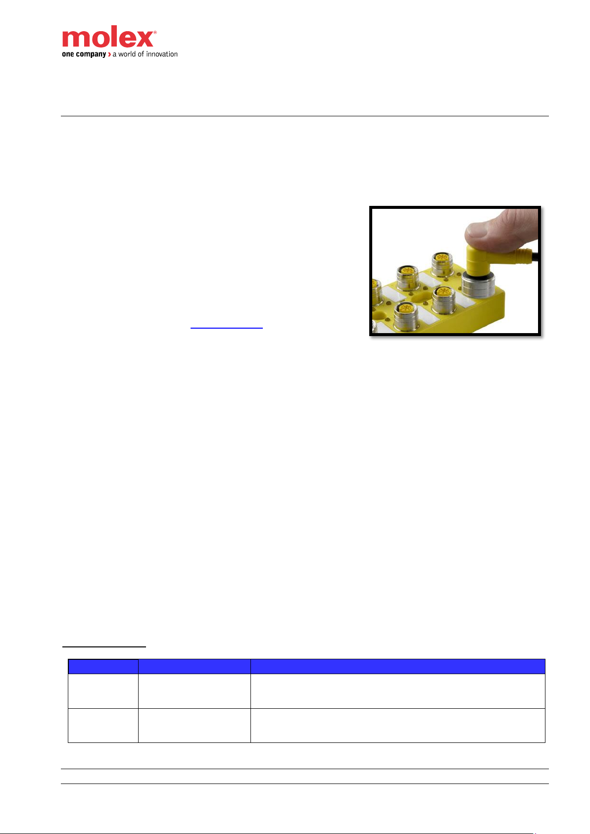
All Brad™ HarshIO modules, with Micro-Change® (M12) ports,
accept both standard threaded cordsets and the Molex
Ultra-Lock™ system.
Ultra-Lock™ connection System! The fastest, easiest and most
secure connection ever designed. Ultra-Lock™ technology is
designed for higher performance and reliability. Discover how the
push-to-lock technology of the Ultra-Lock connection system can
eliminate your downtime, increase your productivity and lower your
costs. More information visit: www.molex.com .
Brad™ HarshIO includes advanced diagnostic features. Each module embeds visible LEDs to provide
maintenance personnel the ability to easily determine I/O module and network status. These statuses are also
available through the process data image or via extended slave diagnostics.
Brad™ HarshIO main features include:
▪ Module is housed in an IP67 rated enclosure that when properly installed—according to IEC 60529—
provides protection against the ingress of dust, water
▪ 8x IO-Link Master configurable channels (IO-Link or SIO) + 8 digital user configurable I/O channels
(DIO)
▪ 4-pole or 5-pole Mini-Change (7/8) power supply connector
▪ Digital input and output short circuit protection
▪ Integrated 2-port unmanaged Ethernet switch with cross-over and DLR capabilities
▪ Diagnostic visible leds
▪ Rotary switches for IP address, firmware update and factory reset modes
▪ ODVA conformance tested
▪ Certifications:
o CE compliant for all applicable EC directives
o FCC Title 47, Part 15, Subpart B, Class A
o REACH / MCSS
o CSA C22.2 No. 142
o IEC 61131-4
o ROHS china
o EMC directive for industrial use
o UL94-V0
Part Number Table
SAP No
Material No
Description
112095-5122
TCIEI -888P-DYU
IP67 module for EtherNet/IP, 60mm format, 4-pole power
connector, 8x IO-Link + 8x I/O configurable, PNP
112095-5121
TCIEI-888P-D1U
IP67 module for EtherNet/IP, 60mm format, 5-pole power
connector, 8x IO-Link + 8x I/O configurable, PNP
Page 10

HarshIO 600 eIP
•
10 • IP67 IO-Link Modules for EtherNet/IP
Overview
The HarshIO module is consisted of three main parts.
Page 11

HarshIO 600 eIP
•
11 • IP67 IO-Link Modules for EtherNet/IP
Power distribution
HarshIO EtherNet/IP IO-Link Master modules can be powered up through 4-pole or 5-pole Mini-Change (7/8”)
power supply connectors identified by 2 different part numbers. This specificity allows complying with regional
power requirements.
The HarshIO module integrates 2 power connectors 1x Male and 1x Female for daisy chain installation
simplifying the power distribution across the application.
The Mini-Change (7/8) connectors can supply or transfer total amperage of 8 A per pin.
Network topologies
HarshIO EtherNet/IP IO-Link Master modules can be used with a protocol compliant controller as part of
control system architecture. The built-in unmanaged 2-port Ethernet switch allows flexibility in the network
topology to meet your application needs. These topologies include the following:
• Star
• Daisy-chain
• Ring (using DLR protocol)
• Combination of all above
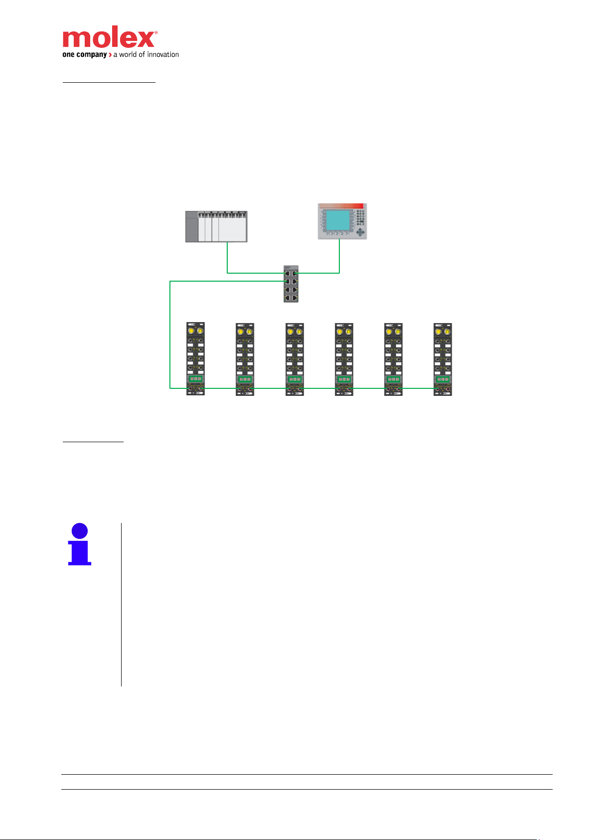
Star topology
Star topology allows you to connect mixed I/O modules or additional equipment. This topology allows
maintenance on one module – for example, by removing the network cable, or by power cycling to the module
– without affecting the other modules.
HMI
Ethernet
Switch
PLC
Page 12
HarshIO 600 eIP
•
12 • IP67 IO-Link Modules for EtherNet/IP
Daisy-chain topology
The daisy-chain topology allows you to connect I/O modules or additional equipment in one line, from one
device to the next in an optimized way along the production line.
When considering the daisy chain topology, note that
• If a module, somewhere in the middle of the chain, has the network cable disconnected or power to the
module is removed then communications to any module located down the chain will be lost.
• The embedded dual port Ethernet switch located in each module eliminates the need for additional
Ethernet switches.
HMI
Ethernet
Switch
PLC
Ring topology
Ring topology allows you to include mixed HarshIO modules and additional devices in a ring. Performing
maintenance on one module – for example, by removing the network cable, or by removing a module – does
not affect other modules as the disruption can be detected and the EtherNet/IP communication can be then
routed adequately. To manage the ring, a specific protocol called DLR (Device Level Ring) is required.
Note!
When considering DLR ring topology:
• A device called ring Supervisor shall be present in the ring to control the
administration and detects the network failures. The other participants are
called DLR Ring Node Announce or Beacon-based.
• Multiple DLR ring Supervisors can be inserted in the ring to improve the
media reliability.
• DLR protocol is a single fault tolerant mechanism. When a failure is
detected, body operations must be performed as soon as possible to
recover the fault.
• HarshIO modules are DLR Ring Node Beacon-based.
Page 13

HarshIO 600 eIP
•
13 • IP67 IO-Link Modules for EtherNet/IP
Combination of various topologies
Combining star and daisy-chain topologies allows you to connect HarshIO modules with mixed HarshIO
modules or additional network devices.
HMI
Ethernet
Switch
PLC
Page 14
HarshIO 600 eIP
•
14 • IP67 IO-Link Modules for EtherNet/IP
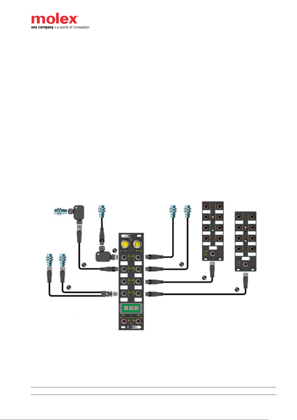
Signal
The HarshIO module supports up to 8 I/O ports with each:
• 1x Channel with IO-Link Master communication on Pin 4
• 1x Channel with user configurable digital I/O on Pin 2
The IO-Link Master communication channels can behave as a standard digital Input or Output or connect
any IO-Link devices such as:
• Brad™ IO-Link digital hub – 16 inputs (TEDIO-8D0P-808)
• Brad™ IO-Link digital hub – 12 inputs + 4 outputs (TEDIO-8B4P-808)
• Any other IO-Link devices on the market
The configurable digital output on Pin 2 can deliver up to 2A for actuators with high power requirements. This
output can also be used as additional power supply for the outputs of the Brad IO-Link digital hub 12 inputs + 4
outputs (TEDIO-8B4P-808).
HarshIO module is a high modular system. In combination with the Brad IO-Link digital hubs, the users can
interconnect up to:
• 136 digital Inputs max (using Brad IO-Link digital hubs - 16 input)
• 40 digital outputs max + 96 digital Inputs (Brad IO-Link digital hubs - 12 inputs + 4 outputs)
This modularity allows to optimize the use of each I/O channels of the module and to reduce significantly the
installation cost.
Page 15

HarshIO 600 eIP
•
15 • IP67 IO-Link Modules for EtherNet/IP
3. Technical Data
Dimensions (mm)
Page 16
HarshIO 600 eIP
•
16 • IP67 IO-Link Modules for EtherNet/IP
Electrical Power Data
Module
4-pin power version
5-pin power version
Product Reference
TCIEI-888P-DYU
TCIEI-888P-D1U
Power
Power IN connector
Mini Change (7/8”), 4-pin, male, Maximum 8 A
Mini Change (7/8”), 5-pin, male, Maximum 8 A
Power OUT connector
Mini Change (7/8”), 4-pin, female, Maximum 8 A
Mini Change (7/8”), 5-pin, female, Maximum 8 A
Module & Input power (UB)
24 VDC, -20%/+25% (19.2 VDC / 30 VDC) protected against power crossing)
Warning, a voltage over 30 VDC may destroy the module
Operating current (UB)
87 mA
Output power (UL)
10 Amps
Over current detection:1.45 x 8 A (±15%) for at least 250ms
Operating current (UL)
24 VDC, -20%/+25% (19.2 VDC / 30 VDC) (protected against power crossing)
Warning, a voltage over 30 VDC may destroy the module
Functional Earth
10 Amps
Over current detection:1.45 x 8 A (±15%) for at least 250ms
Max draw current per I/O connector
4 A
Sensor power pin
Pin 1 (L+ / Sensor power supply)
Sensors draw current from
UB
Maximum current (per port)
1.6 A (L+)
Electrical Signal Data
Channels
Pin 2 (configured as)
Pin 4 (configured as)
I/O connector
M12 Ultra-Lock, 5-pole, female, A-Coded
Standard Digital Inputs
Number of Channel
8 channels max
8 channels max
Input type
PNP, compliant to IEC 61131-2 Type 3
PNP, compliant to IEC 61131-2 Type 1
On-state current
2.5 mA typ.
2.5 mA typ.
Off-state current
1 mA max.
1 mA max.
Input channel voltage (“1”)
10 V … 30 V
12 V … 30 V
Input channel voltage (“0”)
-5 V … 5 V
-5 V … 9 V
Input filter
0, 1, 3 and 5 ms (1ms by default)
500 ns
Standard Digital Outputs
Outputs draw current from
UL
UB
Channels
8 channels max
8 channels max
Output voltage (min)
UL – 1V
UB – 1V
Output type
PNP, current sourcing
PNP, current sourcing
Output current
2 A per channel
0.5 A per channel
Maximum output current
8.0 A at 25°C ; total for all outputs combined
8.0 A at 25°C ; total for all outputs combined with
all sensor supply current
Short circuit current (typical)
up to 6.5 A
up to 1.2 A
IO-Link C/Q
Number of IO-Link channels
N/A
8 channels max
IO-Link port type
N/A
Port class A
Physical interface
N/A
Support of COM1, COM2, COM3
Max Process Data length
N/A
32 bytes
Protocol
N/A
Compliant with IO-Link specifications
v1.1 and v1.0
Page 17
HarshIO 600 eIP
•
17 • IP67 IO-Link Modules for EtherNet/IP
Note!
The I/O port can supply power from the following pin:
• Pin1 1.6 A
• Pin 2 2 A
• Pin 4 500 mA
All current supplied will be returning through Pin3 (L-). Make sure that the total current
on Pin3 does not exceed 4 A (M12 standard max current support). Therefore, the over
current will be detected either on Pin 1, Pin 2 or Pin 4 and the electrical protection will
be triggered.
Warning!
To comply with CE directives, the module shall be powered from a Safety Extra-Low
Voltage (SELV-) or a Protected Extra-Low Voltage (PELV-) power supply according to
IEC 50178.
Warning!
The product shall be powered using a Class 2 Power Supply.
Warning!
The digital outputs of the product are internally protected against voltage spikes due to
inductive load switching. Nevertheless, an external protection (freewheeling diode)
could be added if necessary.
Warning!
When a potential is applied on SIO/IO-Link channel (Pin 4), the difference between the
value of this external potential and the UB shall not be higher than 0.3 V.
A value higher than 0.3 V will result a destruction of the HarshIO module.
An external potential with a value lower than UB is accepted.
Note!
Shields of I/O connectors are not connected to earth. If shielded cable is used, then
customer should connect the cable shield to the earth.
Page 18

HarshIO 600 eIP
•
18 • IP67 IO-Link Modules for EtherNet/IP
EtherNet/IP
EtherNet/IP Fieldbus
Ethernet connectors
2 x M12, 4-pin, female, D-Coded, shielded
IP setting
DHCP (based on MAC & on Client_ID), Static IP, Stored IP
Protocol
EtherNet/IP Adapter according specification Vol 1-3.17 (CIP) and Vol 2 – 1.18 (EtherNet/IP)
Data access
Implicit messages for I/O data transfer
Implicit (I/O) connection
• 1x Exclusive Owner (EO) connection (with configuration data only)
• Up to 7 Listen Only (LO) connections (with or without configuration data)
• Up to 8 Input Only (IO) connections (with or without configuration data)
• 8 simultaneous connections (Ex: 1EO+ 4IO +3LO)
Explicit (EM) connection
• Up to 8 Class 3 connections (Connected and unconnected)
Supported CIP Objects
• 0x01 – Identity object
• 0x02 – Message Router object
• 0x04 – Assembly object
• 0x06 – Connection Manager object
• 0x37 – File object (EDS Upload & Upload/Download/Clear DS file)
• 0x47 – DLR object
• 0x48 – QoS object
• 0xF5 – TCP/IP Interface object
• 0xF6 – Ethernet Link object
• 0x 310 – IO-Link object
Integrated Switch
• 2x ports integrated switch (with DLR capability)
• Speed: 100Mbps
• Auto negotiation
• Auto crossing
• Auto polarity
• 1x status Led / port
• Storm Protection against network loop (Broadcast, Multicast and Unicast packets)
Ethernet Packet
Manage up to 9000 packet/sec
Request Packet Interval (RPI)
from 1 ms up to 65535 ms (default 30 ms)
IP Address Conflict Detection
Yes
Quick Connect
Yes
DLR (Device Level Ring)
Yes (Ring Node, Beacon-Based)
QoS (Quality of Service)
Yes (Layer 3 supported only)
ODVA conformance
Yes (CT13)
Page 19
HarshIO 600 eIP
•
19 • IP67 IO-Link Modules for EtherNet/IP
Mechanical and Environmental Data
Mechanical
Housing dimensions
235 x 60 x 39 mm (9.25" x 2.36” x 1.53")
Housing material
PBT VALOX 420 SEO Black 7701
Flammability Standard
UL 94 V-0
Corner mounting holes
4 mounting holes, 5 x10 mm
Ground stud
Yes (allows the continuity of the ground when the module is mounted on the chassis machine)
Operating temperature
-25°c to +70°c
Storage temperature
-40°c to +90°c
Vibration resistance
Operating: 7mm p-p (5-15.7Hz), 7g (15,7Hz to 500Hz), 3 axis
Shock resistance
Operating: 15g, 11ms, 3 axis / Non-operating: 50g, 6ms, 3 axis
Electro-magnetic compatibility
EN 61000-6-2 / EN 61000-6-4
Relative humidity
10 % to 95 %, non-condensing
Protection Class
IP67
Approval
CE (according IEC 61131-2), UL / cUL
Environmental
RoHS and REACH
MTBF
100.000 Hours @ 70°C
Note!
This product was EMC tested for use in industrial areas. If it is to be used in personal or
business and trade environments, the resulting system must go through EMC
qualification.
Page 20
HarshIO 600 eIP
•
20 • IP67 IO-Link Modules for EtherNet/IP
4. System Description
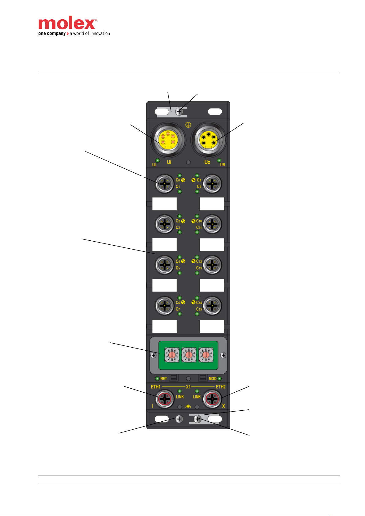
Physical description
Power IN (Ui)
Power OUT (Uo)
Mounting screw (Functional Earth #0 – FE0)
I/O Connectors
Plastic label
3x Rotary switches
Ethernet Port (ETH1)
Ethernet Port (ETH2)
Mounting screw
(Functional Earth #2 - FE2)
Port 0
Port 1
Port 2
Port 3
Port 4
Port 5
Port 6
Port 7
Shield Plate
Shield Plate
Mounting screw
(Functional Earth #1 – FE1)
Page 21
HarshIO 600 eIP
•
21 • IP67 IO-Link Modules for EtherNet/IP
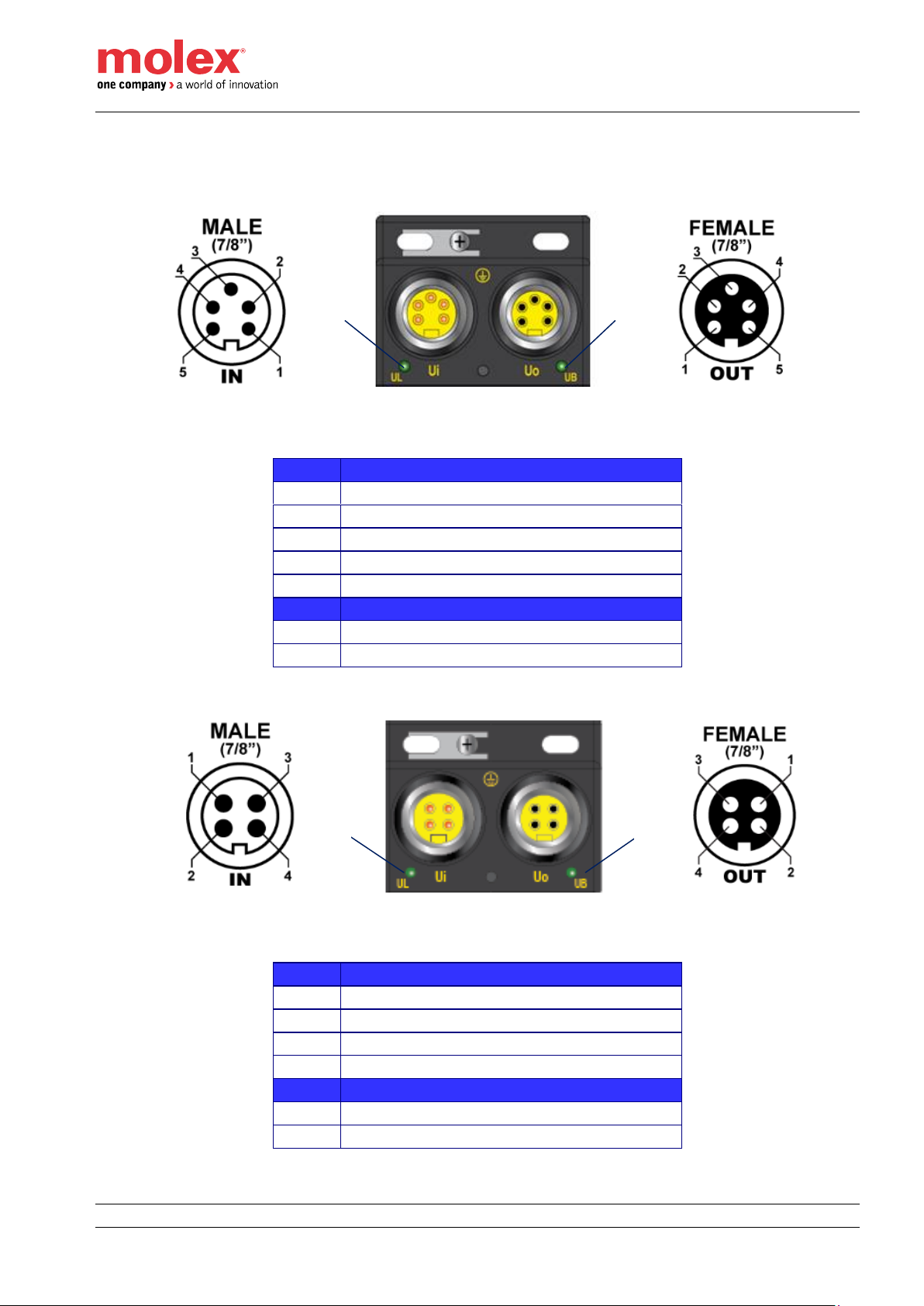
Power connectors
Pinout and orientation
Pin
5 pins Power Connector - Description
1
0 V 2 0 V
3
FE (Functional Earth)
4
24 VDC (UL - Outputs power supply)
5
24 VDC (UB - Module & Inputs power supply)
LEDs
6
UL indicator
7
UB indicator
Pin
4 pins Power Connector - Description
1
24 VDC (UL - Outputs power supply)
2
24 VDC (UB - Module & Inputs power supply)
3
0 V 4 0 V
LEDs
5
UL indicator
6
UB indicator
TCIEP-888P-D1U
TCIEP-888P-DYU
6 7 5
6
Page 22
HarshIO 600 eIP
•
22 • IP67 IO-Link Modules for EtherNet/IP
Note!
The shell of each Power IN/OUT connector is connected to PE screw tab.
Refer to Earth connection part
Note!
7/8” accessories (cordsets, plugs …) connected to the module power connectors shall
be screwed with a torque of 2.0 Nm to ensure a correct sealing to achieve IP67 rating.
Warning!
User has to verify that the maximum current consumption that can be reached ( e.g. all
output active at the same time,…) is lower than the maximum limit on all the range of
temperature supported by the application
Warning!
A overcurrent protection (ex: fuse) shall be added in front of IO modules to avoid
possible destruction in case of over-current situation
Power supplies
The HarshIO module can be powered by 2 separate power supplies:
• UB power supply is used to power:
o Module’s logic
o Digital inputs (I/O connector Pin 1)
o Standard Input/ Output SIO and IO-Link (I/O connector Pin 4)
• UL power supply is used to power:
o Digital outputs only (I/O connector Pin 2)
o It also provides extended power to Brad IO-Link digital hub (I/O connector Pin 2)
There is no separate grounding between UB and UL. It means that 0V (UB) and 0V (UL) are connected.
The +24 voltage can be applied on Module/Inputs power supply (UB) and Outputs power supply (UL) from
separate or unique power supply source.
Note!
You can only apply +24 voltage on UB if you only use the inputs.
The maximum amperage capability of the power connectors is limited to 8A and users have to make sure that
the current consumption of the HarshIO module, the connected devices to the IO ports as well as the
subsequent daisy chained modules would not exceed this consumption limit.
Note!
UB & UL support a power interruption according to EN 60204-1.
Note!
If you only use digital input devices, there is no need to supply power on UL.
UL is only required for Outputs on Pin2 or Extended power supply for Molex IO-Link
I/O Hubs.
Page 23
HarshIO 600 eIP
•
23 • IP67 IO-Link Modules for EtherNet/IP
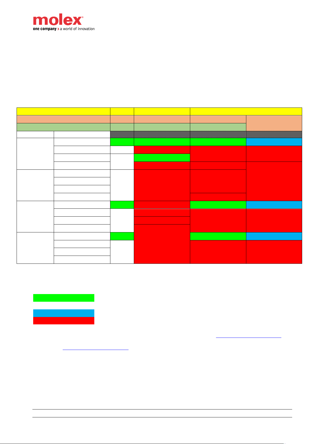
Protection strategies on electrical faults
Multiple electrical faults may occur (intentionally or not) which are:
- Overload / Overcurrent
- Short Circuit
- Under voltage
- Over voltage
According to the type, protection strategies are applied for Pin 1, Pin 2 and Pin 4 according to the IO
configuration and on all the ports or on a single one depending on the type of issue. See table below.
PIN
1
2
4
Mode
24V
DO
SO
IOL
State
Power 1 1
UL
UB
Nominal
voltage (24v)
Nominal voltage (24v)
ON
ON
ON
BLUE
OverCurrent > ~10A
OFF (1)
Reset all pins to 0 (2)
Reset all pins to 0 (2)
Reset all pins to 0 (2)
UnderVoltage < 19,2V
OFF (1)
ON
OverVoltage > 30V
Reset all pins to 0 (2)
Reset all pins to 0 (1)
Data invalid (1)
OverCurrent
> 10A
Nominal voltage (24v)
OFF (1)
Reset all pins to 0 (2)
Reset all pins to 0 (2)
OverCurrent > ~10A
UnderVoltage < 19,2V
OverVoltage > 30V
Reset all pins to 0 (1)
UnderVoltage
< 19,2V
Nominal voltage (24v)
ON ON
BLUE
OverCurrent > ~10A
OFF (1)
Reset all pins to 0 (2)
Reset all pins to 0 (1)
Data invalid (1)
UnderVoltage < 19,2V
OverVoltage > 30V
Reset all pins to 0 (2)
OverVoltage
> 30V
Nominal voltage (24v)
ON
ON
BLUE
OverCurrent > ~10A
OFF (1)
Reset all pins to 0 (1)
Data invalid (1)
UnderVoltage < 19,2V
OverVoltage > 30V
DO: Digital output configured on Pin2
SO: Standard Digital output configured on Pin4
IOL: IO-Link configured on Pin4
ON
LED fixed green & Pin energized
OFF
LED off & Pin not energized
BLUE
LED fixed blue & IO-Link operational
LED fixed red & diagnostic available
(1) Automatic acknowledgement only, even if EFAM=1 – Refer to the chapter Configuration Data mapping
(2) Manual (EFAM=0) and Automatic (EFAM=1) acknowledgement possible – Refer to
the chapter Configuration Data mapping
Page 24
HarshIO 600 eIP
•
24 • IP67 IO-Link Modules for EtherNet/IP
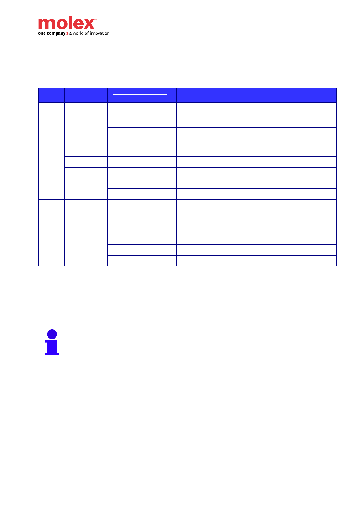
LEDs and status bits
The table below shows the LEDs state according to power supply voltages applied and the corresponding
status bits.
LEDs
Color State
Input Process data -
Status bit
State & Power supply voltages
UL
Off
No error
Voltage not present (UL=0 V)
If no DO configured
Powered and UB not powered
UVUL =1
Voltage not present (UL=0 V)
• If DO configured & energized
• Hub 12/4 configured with PIN 2 used as
auxiliary power
Fixed green
No error
Voltage present 19.2 V ≤ UL ≤ 30 V
Fixed red
UVUL =1
Voltage 0 V < UL <19.2 V
OVUL =1
Voltage over 30 V
OLUL =1
Overload (8 A) *
UB
Off
No error
Voltage < 11 V
• If UB < 11V, HarshIO will shutdown
• If UB > 13V, HarshIO will boot up
Fixed green
No error
Voltage present 19.2 V ≤ UL ≤ 30 V
Fixed Red
UVUB =1
Voltage 0 V < UL <19.2 V
OVUB =1
Voltage over 30 V
OLUB =1
Overload (8 A) *
(*): a ratio is applied on 8A. The real threshold is 8A x1.45
UVx: Under Voltage (x = UL or UB)
OVx: Over Voltage (x = UL or UB)
OLx: Over Load (x = UL or UB)
DO: Digital Output configured on Pin2
Note!
As IO-Link operation voltage is defined above 18V, IO-Link communication will be
reinitialized if UB goes down under 17V and comes back up to 19.2V.
Page 25

HarshIO 600 eIP
•
25 • IP67 IO-Link Modules for EtherNet/IP
Ethernet connectors and encoding switches
Pinout and orientation
Note!
Shell of each connector (FE1 & FE2) is connected to its own FE screw tab.
Note!
M12 Ethernet connector shall be screwed with a torque of 2.0 Nm to ensure a correct
sealing to achieve IP67 rating.
Ethernet LEDs
LED
Color State
Meaning
LINK ETH
Fixed yellow
10MB* + No Activity
Blinking yellow
10MB* + Activity
Fixed Green
100MB + No Activity
Blinking Green
100MB + Activity
(*): 10MB is not supported (100MB only)
Pin
Description
1
TX+
2
RX+
3
TX-
4
RX-
Link ETH1 indicator
Link ETH2 indicator
No LED - black light-pipe only
Page 26

HarshIO 600 eIP
•
26 • IP67 IO-Link Modules for EtherNet/IP
Networks LEDs
The left side bi-color red/green LED is network status indicator (NET) and the right side bi-color red/green LED
is internal module status indicator (MOD).
LED
Color State
Meaning
NET
OFF
No UB power supply or no IP address assigned
Blinking Red
IP address assigned & connection time-out
Rotary position changed while IO exchange running
Fixed Red
IP Conflict detected (Duplicate IP)
Fixed Green
IP address assigned & connection established (no communication problem)
Blinking Green
IP address assigned & no connection established
Blinking Green/Red
Self-test on power up
MOD
OFF
No UB power supply
Blinking Red
Major Recoverable Fault
- IP Conflict detected
- Rotary position changed while IO exchange running
- Configuration Control changed (Set attr3 object 0xF5)
- Interface Configuration changed (Set attr5 object 0xF5)
- IP lost (Ex : DHCP mode)
Fixed Red
Major Unrecoverable Fault
Fixed Green
Module is started and operational
Blinking Green
Module is started but no configuration has been received through an IO connection yet.
Blinking Green/Red
Self-test on power up
NET indicator
MOD indicator
Page 27

HarshIO 600 eIP
•
27 • IP67 IO-Link Modules for EtherNet/IP
Use of the rotaries
3 decimal rotary switches are located under the window and oriented as shown below. “x100 x10 x1” labels
are printed below of the rotary (PCB silkscreen).
Note!
The module window shall be screwed with a torque of 0.3 Nm to ensure a correct
sealing to achieve IP67 rating and shall be closed during working operation.
The user shall check regularly that the torque of module window is respecting the
screwing value 0.3 Nm
The rotary switch position is only read at the boot of the HarshIO module. Any modification of the position will
require a power cycle (ON OFF ON) or a reset of the module
The HarshIO module is out-of-box configured with rotary position 000. This configuration corresponds to stored
IP address mode 500 with DHCP mode activated. When connecting to a network with a DHCP server, an IP
address is automatically assigned to the module.
Assigning an IP address using 0xF5 TCP/IP Object allows defining permanently this IP address for the
following module startup. No rotary switches modification would be required.
To change or set the IP address, the operator has the possibility to use one of the following methods:
Mode
x100
rotary
x10
rotary
x1
rotary
Descriptions
Static
Address
x
[0 to 2]
y
[0 to 9]
z
[1 to 9]
Overwrite the 4th byte of the IP address stored in non-volatile
memory.
IP Address: 192.168.1.xyz (xyz from 1 to 254)
IP mask: 255.255.255.0
Gateway: 192.168.1.1
Note!
If the IP address is 192.168.1.1 then
the gateway will be 0.0.0.0
Note!
When using static IP address mode,
the IP address is stored in the Flash
memory of the module.
x100
x10
x1
Page 28

HarshIO 600 eIP
•
28 • IP67 IO-Link Modules for EtherNet/IP
DHCP
Mode
(based on MAC
address)
4 0 0
HarshIO module gets its IP address, IP mask address and
gateway address according DHCP method based on MAC
address. It will send the DHCP request indefinitely until
receiving an IP
DHCP
Mode
(based on Client
ID=”BRAD_xy”)
4
y
[0 to 9]
z
[1 to 9]
HarshIO module gets its IP address, IP mask address and
gateway address according DHCP method based on Client
ID=”BRAD_xy”.
It will send the DHCP request indefinitely until receiving an IP
(yz) in the range from 1 to 99 can be allocated
Stored
IP Address
5 0 0
HarshIO module gets its IP address, IP mask address and
gateway address according information stored in its nonvolatile memory.
Note!
The module will start in DCHP mode until
a new mode is configured via Explicit
messages (attr3 object 0xF5).
Module
Reset
9 0 0
EtherNet/IP protocol is not started.
Factory default values below will be applied at the next power
cycle with new rotary position.
▪ IP address: DHCP
▪ Subnet mask: 0.0.0.0
▪ Gateway: 0.0.0.0
▪ ETH1 port: Auto negotiation + Auto-MDI
▪ ETH2 port: Auto negotiation + Auto-MDI
▪ ACD Enabled
▪ QuickConnect Disabled
Update
Firmware
9 9 9
The module enters in the update firmware mode.
Refer to Chapter Firmware update
All other rotary
positions
a b c
Same behavior than position 5 0 0
Note!
When switching from DHCP mode to Static IP mode (attr3 of object TCP/IP 0xF5), the
mask of the IP address will always be 255.255.255.0.
Note!
When switching from DHCP mode to Stored IP mode (attr3 of object TCP/IP 0xF5), the
IP address and the mask will be the ones obtained from the DHCP mode
Note!
The IP mask address and gateway address are the ones stored in the Flash memory of
the module. If you want to change these parameters, you can send explicit messages
command to the module (attr5 of object TCP/IP 0xF5). See section here.
Note!
When using Static IP and DHCP modes, it is not possible to store an IP address using
CIP Explicit messages (attr5 of object TCP/IP 0xF5)
Page 29

HarshIO 600 eIP
•
29 • IP67 IO-Link Modules for EtherNet/IP
Warning!
If you change the rotary position while the EtherNet/IP scanner has an I/O connection
established, the connection will be closed and the Fail Safe Mode will be applied. A
reset command or a power cycle will be required.
I/O connectors
Pinout and orientation
Pin
I/O Connector - Description
Powered by
1
24VDC (L+)
UB
2
D_I/O - Digital Input (DI) or output (DO) - Configurable
UL for DO
3
GND (L-)
4
C/Q, IO-Link data transmission cable. It can also be configured
as Standard Digital Input (SI), Standard Digital Output (SO) and
as Extended Power Supply (EPS)
UB
5
Not connected
LEDs
6
Tri-color red/blue/green LED for even channel indicator– Pin4
7
Bi-color red/green LED for odd channel indicator – Pin2
C/Q
connection for communication (C) or switching (Q) signal (SIO)
Warning!
When a potential is applied on SIO/IO-Link channel (Pin 4), the difference between the
value of this external potential and the UB shall not be higher than 0.3 V.
A value higher than 0.3 V will result a destruction of the HarshIO module.
An external potential with a value lower than UB is accepted.
Note!
Shell of each I/O Port connector is connected to Functional Earth. Refer to Chapter
Functional earth connections.
6
7
Page 30

HarshIO 600 eIP
•
30 • IP67 IO-Link Modules for EtherNet/IP
Note!
M12 accessories (cordsets, plugs …) connected to the module I/O and network
connectors shall be screwed with a torque of 2.0 Nm to ensure a correct sealing to
achieve IP67 rating.
Note!
At the module power up and before the first connection with the PLC, Pin #2 & Pin #4
are configured as Digital Input.
Note!
The IO-Link devices can be connected to the I/O connector via 3, 4 or 5-wire standard
cables with a maximum length of 20 m.
Channel LEDS and status bits
The table below shows the LEDs behavior, the description and the corresponding status bits.
DI:
DO:
SI:
SO:
EPS:
IO-Link:
Digital Input configured on Pin2
Digital Output configured on Pin2
Standard digital Input configured on Pin4
Standard digital Output configured on Pin4
Extended Power Supply
IO-Link configured
LEDs
Color State
Input process data -
Status bit
State & Description
C1, C9
C3, C11
C5, C13
C7, C15
(Pin 2)
OFF
No error
DI configured but not activated (not set to 1)
DO configured but not energized
Fixed green
No error
DI activated.
DO / EPS energized
Fixed red
CSx=1
DO / EPS: when shorted to ground
DO: when overload detected (>500mA)
OVUB =1
All PSx=1
DO / EPS energized and overvoltage on UB (> 30 V)
OLUB =1
All PSx=1
DO / EPS energized and overcurrent on UB (>~10A)
UVUB =1
All PSx=1
DO / EPS energized and under voltage (UB <19.2V)
OVUL =1
DO / EPS: when energized and UL is overvoltage (UL > 30 V)
UVUL =1
DO / EPS: when energized and UL is under voltage (UL <19.2V)
PSx=1
DI/DO/EPS configured: when L+ is shorted
DI/DO/EPS: when L+ is overloaded (1.6A)
C0, C8
C2, C10
C4, C12
C6, C14
(Pin 4)
OFF
No error
SI not activated
SO not energized
IO-link is not activated
Fixed green
No error
Shows the status of the Port in SIO mode:
- SI activated
- SO energized
Fixed blue
IOLSx = 0 & IOLDx=0
The BLUE led shows the actual IO-Link communication state
IO-link Device connected and in OPERATE state.
Page 31

HarshIO 600 eIP
•
31 • IP67 IO-Link Modules for EtherNet/IP
Blinking
blue
IOLSx =3 & IOLDx=1
IOLSx =0 & IOLDx=1
The BLUE led shows the actual IO-Link state:
Blinking at 1 Hz: searching device, wakeup mode
Blinking at 2 Hz: device found and in state PREOPERATE
Fixed red
CSx=1
SO: energized and shorted to ground
SO: when overload detected (>500mA)
UVUB =1
All PSx=1
IOLSx # 0 (if configured)
Under voltage (UB <19.2V) when SO energized or IO-Link
configured
OVUB =1
All PSx=1
IOLSx # 0 (if configured)
Overvoltage on UB (> 30 V) when SO energized or IO-Link
configured
OLUB =1
All PSx=1
IOLSx # 0 (if configured)
Overcurrent on UB (>~10A) when SO energized or IO-Link
configured
OLUL =1
All PSx=1
IOLSx # 0 (if configured)
Overcurrent on UL (>~10A) when SO energized or IO-Link
configured
Blinking red
PSx=1
Blinking at 1 Hz: SI: L+ is shorted
Blinking at 1 Hz: SI: L+ is overloaded (1.6A)
IOLSx # 0
Blinking at 2 Hz: IO-Link device connected but validation failed
CSx:
UVx:
OVx:
OLx:
PSx:
IOLSx:
IOLDx:
Channel Status (x = Channel number)
Under Voltage (x = UL or UB)
Over Voltage (x = UL or UB)
Over Load (x = UL or UB)
Port Status (x = Channel number) - state of the pin1 (L+)
IO-Link Status
IO-Link Data Valid
Page 32

HarshIO 600 eIP
•
32 • IP67 IO-Link Modules for EtherNet/IP
Functional earth connections
The functional earth (FE0) shall always be connected to ground to ensure proper operation of the module.
The two functional earth (FE1 & FE2) are not connected to the functional earth (FE0).
Note!
3 screw terminals functional earth connections (FE0 / FE1 / FE2) are galvanically
isolated.
Functional Earth N°0 (FE0)
Functional Earth N°1 (FE1)
Functional Earth N°2 (FE2)
Page 33

HarshIO 600 eIP
•
33 • IP67 IO-Link Modules for EtherNet/IP
According to its position, the shield plate offers different functional earth connection to ground.
Switch
Switch
Page 34

HarshIO 600 eIP
•
34 • IP67 IO-Link Modules for EtherNet/IP
5. I/O Data mapping
I/O messaging
HarshIO module supports up to a maximum of 8 I/O connections. Fewer connections allow faster data I/O
update rates (RPI value).
I/O Connections:
- HarshIO module supports 2 transport Class 1 I/O connections (Cyclic and Change-Of-State
triggers):
o 1x Exclusive Owner
▪ Unicast or Multicast (TO) connection
▪ Unicast (OT) connection
o 7x Listen Only or Input Only (8 Input Only connection if no Exclusive Owner connection)
▪ Multicast or Unicast (TO) connection
Note!
Listen Only connection allows a second Ethernet/IP scanner connected to the
network to listen the Input process data. For example, this feature is useful to
share easily Inputs with a HMI/Scada application.
Page 35

HarshIO 600 eIP
•
35 • IP67 IO-Link Modules for EtherNet/IP
EtherNet/IP Assembly instances
The I/O process data are available through the EtherNet/IP assembly instances. Below the list according to the
connection type.
Input
Assembly
Data length
(bytes)
Output
Assembly
Data length
(bytes)
Configuration
Assembly
Data length
(bytes)
EDS entry
Exclusive Owner
Digital I/O & Status
110 8 121
36
100
260
None
Digital I/O & Status + IO-link with 4 bytes I/O
111
88
121
36
100
260
EO_PD_4 bytes
Digital I/O & Status + IO-link with 8 bytes I/O
112
120
122
68
100
260
EO_PD_8 bytes
Digital I/O & Status + IO-link with 32 bytes I/O
113
312
123
260
100
260
EO_PD_32 bytes
Input Only
Digital I/O & Status
110 8 198 0 100
260 or 0
IO_Status or
IO_Status-No Conf
Digital I/O & Status + IO-link with 4 bytes I/O
111
88
198 0 100
260 or 0
IO_PD_4 bytes or
IO_PD_4 bytes-No Conf
Digital I/O & Status + IO-link with 8 bytes I/O
112
120
198 0 100
260 or 0
IO_PD_8 bytes
IO_PD_8 bytes-No Conf
Digital I/O & Status + IO-link with 32 bytes I/O
113
312
198 0 100
260 or 0
IO_PD_32 bytes
IO_PD_32 bytes-No Conf
Listen Only
Digital I/O & Status
110 8 199 0 100
260 or 0
LO_Status
LO_Status-No Conf
Digital I/O & Status + IO-link with 4 bytes I/O
111
88
199 0 100
260 or 0
LO_PD_4 bytes
LO_PD_4 bytes-No Conf
Digital I/O & Status + IO-link with 8 bytes I/O
112
120
199 0 100
260 or 0
LO_PD_8 bytes
LO_PD_8 bytes-No Conf
Digital I/O & Status + IO-link with 32 bytes I/O
113
312
199 0 100
260 or 0
LO_PD_32 bytes
LO_PD_32 bytes-No Conf
Note!
If your EtherNet/IP scanner configuration tool does not support the management of
EDS files, you may have to configure manually the assembly numbers to access
the process data.
– Example of HarshIO assembly setting
in Rockwell Automation RSLogix 5000 software –
Page 36

HarshIO 600 eIP
•
36 • IP67 IO-Link Modules for EtherNet/IP
Input process data mapping
Assembly #110 - Digital data + with no IO-Link data
Process Input Data (8 bytes)
Bit
Offset (in byte)
7 6 5 4 3 2 1 0 00
DI7
SI6
DI5
SI4
DI3
SI2
DI1
SI0
01
DI15
SI14
DI13
SI12
DI11
SI10
DI9
SI8
02
PS7
PS6
PS5
PS4
PS3
PS2
PS1
PS0
03
n/u
OLUL
OVUL
UVUL
n/u
OLUB
OVUB
UVUB
04
CS7
CS6
CS5
CS4
CS3
CS2
CS1
CS0
05
CS15
CS14
CS13
CS12
CS11
CS10
CS9
CS8
06 IOML6
IOLM4
IOLM2
IOLM0
07 IOLM14
IOLM12
IOLM10
IOLM8
SIx: SI - Standard Input data (x = Channel number) – Pin4
DIx: DI - Digital Input data (x = Channel number) – Pin2
PSx: Port Status (x = Port number) - state of the pin1 (L+)
1: short circuit detected
0: No default
UVx: Under Voltage (x = UL or UB)
1: Under voltage detected
0: No default
OVx: Over Voltage (x = UL or UB)
1: Over voltage detected
0: No default
OLx: Over Load (x = UL or UB)
1: Over load detected
0: No default
CSx: Channel Status (x = Channel number) – State of the Digital Output (DO – pin 2) or Standard Output (SO
– pin 4)
1: short circuit detected
0: No default
IOLMx: IO-Link Communication Mode (x = Channel number)
0: IO-Link communication not activated
1: IO-Link communication activated
Page 37

HarshIO 600 eIP
•
37 • IP67 IO-Link Modules for EtherNet/IP
Assembly #111 - Digital data + with 4 bytes data per IO-Link device
Input Process Data (8 bytes)
Bit
Offset (in byte)
7 6 5 4 3 2 1
0
00
DI7
SI6
DI5
SI4
DI3
SI2
DI1
SI0
01
DI15
SI14
DI13
SI12
DI11
SI10
DI9
SI8
02
PS7
PS6
PS5
PS4
PS3
PS2
PS1
PS0
03
n/u
OLUL
OVUL
UVUL
n/u
OLUB
OVUB
UVUB
04
CS7
CS6
CS5
CS4
CS3
CS2
CS1
CS0
05
CS15
CS14
CS13
CS12
CS11
CS10
CS9
CS8
06 IOLM6
IOLM4
IOLM2
IOLM0
07 IOLM14
IOLM12
IOLM10
IOLM8
Offset (in byte) per IO-Link channel
IO-Link Process Data (4 bytes)
C0
C2
C4
C6
C8
C10
C12
C14
8
18
28
38
48
58
68
78
IO-Link Input Process Data (4 bytes)
12
22
32
42
52
62
72
82
IOLS (Bits 0-14) + IOLD (bit 15) (2 bytes)
14
24
34
44
54
64
74
84
IOL_LE_SC (1 bytes)
15
25
35
45
55
65
75
85
IOL_LE_EQ (1 bytes)
16
26
36
46
56
66
76
86
IOL_LE_EC (2 bytes)
For Input Process Data information, refer to input assembly #110
IO-Link Input Process Data: Area where the IO-Link process data are mapped.
IOLS - IO-Link Communication Status with device
• 0 – Device is connected and no errors detected
• 1 – Device is not connected
• 2 – Device Lost
• 3 – Detection in progress
• 6 – Invalid revision ID
• 7 – Invalid vendor ID
• 8 – Invalid device ID
• 9 – Invalid serial number
• 10 – Invalid cycle
• 11 – Channel is configured as standard IO
• Other – Please contact tech support
IOLD - IO-Link Data Valid
• 1 – Data is valid
• 0 – Data is invalid
IOL_LE_SC – IO-Link Last Event: Sequential Count
This parameter is the number of the latest IO-Link events. When a new event occurs, this counter is
incremented by 1.
IOL_LE_EQ - IO-Link Last Event: Evt Qualifier
This parameter provides the instance, the source, the type and the mode of the event.
Refer to chapter IO-Link Events & errors codes
IOL_LE_EC - IO-Link Last Event: Evt Code
This parameter provides the event code. Please refer to the specific IO-Link device data sheet for the definition
of the event codes.
Refer to chapter IO-Link Events & errors codes
Page 38

HarshIO 600 eIP
•
38 • IP67 IO-Link Modules for EtherNet/IP
Assembly #112 - Digital data + with 8 bytes data per IO-Link device
Input Process Data (8 bytes)
Bit
Offset (in byte)
7 6 5 4 3 2 1
0
00
DI7
SI6
DI5
SI4
DI3
SI2
DI1
SI0
01
DI15
SI14
DI13
SI12
DI11
SI10
DI9
SI8
02
PS7
PS6
PS5
PS4
PS3
PS2
PS1
PS0
03
n/u
OLUL
OVUL
UVUL
n/u
OLUB
OVUB
UVUB
04
CS7
CS6
CS5
CS4
CS3
CS2
CS1
CS0
05
CS15
CS14
CS13
CS12
CS11
CS10
CS9
CS8
06 IOLM6
IOLM4
IOLM2
IOLM0
07 IOLM14
IOLM12
IOLM10
IOLM8
Offset (in byte) per IO-Link channel
IO-Link Process Data (8 bytes)
C0
C2
C4
C6
C8
C10
C12
C14
8
22
36
50
64
78
92
106
IO-Link Input Process Data (8 bytes)
16
30
44
58
72
86
100
114
IOLS (Bits 0-14) + IOLD (bit 15) (2 bytes)
18
32
46
60
74
88
102
116
IOL_LE_SC (1 bytes)
19
33
49
61
75
89
103
117
IOL_LE_EQ (1 bytes)
20
34
50
62
76
90
104
118
IOL_LE_EC (2 bytes)
For Input & IO-Link Process Data information, refer to input assembly #110 & assembly #111
Assembly #113 - Digital data + with 32 bytes data per IO-Link device
Input Process Data (32 bytes)
Bit
Offset (in byte)
7 6 5 4 3 2 1 0 00
DI7
SI6
DI5
SI4
DI3
SI2
DI1
SI0
01
DI15
SI14
DI13
SI12
DI11
SI10
DI9
SI8
02
PS7
PS6
PS5
PS4
PS3
PS2
PS1
PS0
03 OLUL
OVUL
UVUL
OLUB
OVUB
UVUB
04
CS7
CS6
CS5
CS4
CS3
CS2
CS1
CS0
05
CS15
CS14
CS13
CS12
CS11
CS10
CS9
CS8
06 IOLM6
IOLM4
IOLM2
IOLM0
07 IOLM14
IOLM12
IOLM10
IOLM8
Offset (in byte) per IO-Link channel
IO-Link Process Data (32 bytes)
C0
C2
C4
C6
C8
C10
C12
C14
8
46
84
122
160
198
236
274
IO-Link Input Process Data (32 bytes)
40
78
116
154
192
230
268
306
IOLS (Bits 0-14) + IOLD (bit 15) (2 bytes)
42
80
118
156
194
232
270
308
IOL_LE_SC (1 bytes)
43
81
119
157
195
233
271
309
IOL_LE_EQ (1 bytes)
44
82
120
158
196
234
272
310
IOL_LE_EC (2 bytes)
For Input & IO-Link Process Data information, refer to input assembly #110 & assembly #111
Warning!
If the IO-Link Input Process Data size configured (ex: 4 bytes) is lower than the IO-Link
Input Process Data size of the connected IO-Link device (ex: 32 bytes), the EtherNet/IP
connection will be established and the first 4 input bytes of data will be consumed.
Page 39

HarshIO 600 eIP
•
39 • IP67 IO-Link Modules for EtherNet/IP
Output process data mapping
Assembly #121 - Digital data + with 4 bytes data per IO-Link device
Output Process Data (4 bytes)
Bit
Offset (in byte)
7 6 5 4 3 2 1
0
00
DO7
SO6
DO5
SO4
DO3
SO2
DO1
SO0
01
DO15
SO14
DO13
SO12
DO11
SO10
DO9
SO8
02
CSIC14
CSIC12
CSIC10
CSIC8
CSIC6
CSIC4
CSIC2
CSIC0
03 EFA
Offset (in byte) per IO-Link channel
IO-Link Process Data (4 bytes)
C0
C2
C4
C6
C8
C10
C12
C14
4 8 12
16
20
24
28
32
IO-Link Output Process Data (4bytes)
SOx: SO - Standard Output data (x = Channel number) – Pin4
DOx: DO - Digital Output data (x = Channel number) – Pin2
CSICx: Command to Switch an IO-Link port configured in IO-Link mode to SI mode (x = Channel number –
Pin4). Refer to chapter SI with IO-Link.
• 0 – SI mode
• 1 – IO-Link mode
EFA: Electrical Fault Acknowledgement. This toggle bit is used to manually acknowledge the electrical fault.
Refer to configuration assembly #100 for Electrical Fault Acknowledgement Mode.
IO-Link Input Process Data: Area where the IO-Link process data are mapped.
Assembly #122 - Digital data + with 8 bytes data per IO-Link device
Output Process Data (4 bytes)
Bit
Offset (in byte)
7 6 5 4 3 2 1
0
00
DO7
SO6
DO5
SO4
DO3
SO2
DO1
SO0
01
DO15
SO14
DO3
SO12
DO11
SO10
DO9
SO8
02
CSIC14
CSIC12
CSIC10
CSIC8
CSIC6
CSIC4
CSIC2
CSIC0
03 EFA
Offset (in byte) per IO-Link channel
IO-Link Process Data (8 bytes)
C0
C2
C4
C6
C8
C10
C12
C14
4
12
20
28
36
44
52
60
IO-Link Output Process Data (8 bytes)
For Output and IO-Link Process Data information, refer to output assembly #121 and assembly #122
Assembly #123 - Digital data + with 32 bytes data per IO-Link device
Output Process Data (4 bytes)
Bit
Offset (in byte)
7 6 5 4 3 2 1
0
00
DO7
SO6
DO5
SO4
DO3
SO2
DO1
SO0
01
DO15
SO14
DO3
SO12
DO11
SO10
DO9
SO8
02
CSIC14
CSIC12
CSIC10
CSIC8
CSIC6
CSIC4
CSIC2
CSIC0
03 EFA
Offset (in byte) per IO-Link channel
IO-Link Process Data (32 bytes)
C0
C2
C4
C6
C8
C10
C12
C14
4
36
68
100
132
164
196
228
IO-Link Output Process Data (32 bytes)
Page 40

HarshIO 600 eIP
•
40 • IP67 IO-Link Modules for EtherNet/IP
For Output and IO-Link Process Data information, refer to output assembly #121 and assembly #122
Warning!
If the IO-Link Output Process Data size configured (ex: 4 bytes) is lower than the IOLink Output Process Data size of the connected IO-Link device (ex: 32 bytes), the
EtherNet/IP connection will be established and the first 4 output bytes of data will be
produced.
Configuration data mapping
Assembly #100 - Configuration data
Process Input Data (4 bytes)
Bit
Offset (in byte)
7 6 5 4 3 2 1
0
00
Reserved
EFAM
01
Reserved
GIF
02
Reserved
03
C1
C3
C5
C7
C9
C11
C13
C15
Pin2 Digital Channels
4
36
68
100
132
164
196
228
IO Mode (1 bytes)
5
37
69
101
133
165
197
229
DO Fail Safe Mode (1 bytes)
6
38
70
102
134
166
198
230
DI Invert (1 bytes)
C0
C2
C4
C6
C8
C10
C12
C14
Pin4 Digital Channels
7
39
71
103
135
167
199
231
IO Mode (1 bytes)
8
40
72
104
136
168
200
232
SO Fail Safe Mode (1 bytes)
9
41
73
105
137
169
201
233
SI Invert (1 bytes)
IO-Link Mode
10
42
74
106
138
170
202
234
ID Validation and Data Storage Modes (2 bytes)
12
44
76
108
140
172
204
236
Vendor ID (2 bytes)
14
46
78
110
142
174
206
238
Device ID (3 bytes)
17
49
81
113
145
177
209
241
Reserved
19
51
83
115
147
179
211
243
Direct Param Page2 Enable (1 bytes)
20
52
84
116
148
180
212
244
Direct Param Page2 (16 bytes)
EFAM: Electrical Fault Acknowledgement Mode.
When an electrical fault occurs, the module provides a diagnosis about the event into the input assembly (byte
offset 02/03/04/05) and applies a protection strategy on pin2, pin4 and pin1. (Refer to the chapter Protection
Strategies on electrical fault).
0 = Automatic Acknowledgement and Notification only (NO)
If the electrical fault disappears, the module will automatically acknowledge the error and will remove
the protection strategy and output values are restored.
1 = Manual Acknowledgement and Notification & Protection (NP)
If electrical fault disappears, the module will not automatically acknowledge the error. As soon as the
user manually acknowledges the error (toggle bit “EFA”), the protection strategy is removed. Once
done, it goes in normal mode and output values are restored.
Warning!
Some electrical faults cannot be manually acknowledged even if EFAM is set to 1.
Please refer to chapter Protection Strategies on electrical fault.
Page 41

HarshIO 600 eIP
•
41 • IP67 IO-Link Modules for EtherNet/IP
GIF: Global Input filter
This parameter applies debounce filtering to all digital inputs (DI – Pin2) and prevents the processing of fast
input state changes, like those caused by contact bouncing. Signal changes are ignored according to the filter
time applied and is only registered when the changed polarity has remained fully stable over a given window
time (every new change resets the filter timer).
0: 0ms
1: 1ms
2: 3ms
3: 5ms
IO Mode
This parameter allows configuring the pin2 (channels number C1, C3, C5, C7, C9, C11, C13, C15) and the
pin4 (channels number C0, C2, C4, C6, C8, C10, C12, C14)
For Pin2: For Pin4:
0 = Digital Input (DI) 0 = Standard Input (SI)
1 = Digital Output (DO) 1 = Standard Output (SO)
2 = Extended Power Supply 2 = Standard Input with IO-Link (Refer to chapter SI with IO-Link)
3 = IO-Link
Note!
“Power Supply” on Pin2 is a 24 voltage applied continuously after the EtherNet/IP
connection. It allows to power up the Molex IO-Link hub TEDIO-8D0P-808 and TEDIO8B4P-808.
DO / SO Fail-Safe Mode
This parameter is used for setting the fail-safe value behavior of Digital Output (DO) configured on Pin#2 and
of Standard Digital Output (SO) configured on Pin4.
Fail-safe value will be applied in the below conditions:
- When the Scanner is switched from RUN to PROG (IDLE mode)
- In the event of loss of bus communication (Cable disconnected, connectionTime-out, inhibit mode…)
0 = Reset to 0
1 = Hold Output State. When the communication failure occurs, the output remains in the last state
sent by the PLC
Note!
If Pin#2 is defined as Extended Power Supply, the fail-safe mode will be ignored (Failsafe value not applied).
Note!
If the IO-Link port is in operate mode while the fail-safe mode is triggered, the IO-Link
device will apply its own fail-safe mode. Invalid data status will be indicated into the
Input assembly.
DI / SI Invert
This parameter changes the polarity of the digital inputs. Therefore, the Input Process Data will also report this
inversion.
It could be used to treat normally close sensors in positive logic.
0 = Normal
1 = Inverted
Page 42

HarshIO 600 eIP
•
42 • IP67 IO-Link Modules for EtherNet/IP
ID Validation and Data Storage Modes
Please refer to the chapters ID Validation and Data Storage.
IO-Link provides three levels for the validation of the identity of an IO-Link Device per IO-Link port before
establishing the IO-Link connection.
o None: no ID checking
o Compatible: Vendor ID / Device ID checking
o Identical: Vendor ID / Device ID / Serial number checking
The Data Storage mode is used to define the parametrization strategy in case of replacement.
o Restore: The parameter data are sent from the IO-Link Master to the device
o Backup + Restore: The parameter data can be updated in both directions
Possible values are:
0: None
1: Compatible
2: Compatible with Backup & Restore (Data Storage enabled)
3: Compatible with Restore (Data Storage enabled)
4: Identical
5: Identical with Backup & Restore (Data Storage enabled)
6: Identical with Restore (Data Storage enabled)
VendorID / Device ID
This is the Vendor ID / Device ID of the connected IO-Link device.
Refer to the chapter ID Validation
Direct Param Page2 Enable (DPP2)
This parameter is a parametrization method for IO‐Link device with specifications V1.0. It enables the data
transfer of the Direct Parameter Page 2 to the IO‐Link device.
If validation mode is enabled, DDP2 will be transferred to the IO‐Link device only if the validation is successful.
Possible values are:
0: Not enabled
1: Enabled
Direct Param Page2
The DPP2 describes the area between the IO-Link objects 10hex … 1Fhex. This is a manufacturer specific
range of IO-Link device parameter data. Please refer to the manufacturer user’s manual.
DPP2 Data is an area of 16 Bytes that will be sent in case of DDP2 Enable set from the IO-Link Master to the
IO-Link device at each connection.
Note!
For ease of programming in Studio 5000, Molex provides an AOI (Add-On-Instruction) to use
pre-named tags instead of using Generic tags. Please refer to chapter Rockwell Studio 5000.
Page 43

HarshIO 600 eIP
•
43 • IP67 IO-Link Modules for EtherNet/IP
6. IO-Link Features & Behaviors
IO-Link connection
At the module start up, IO-Link ports are not active. IO-Link connection process starts at reception of the
Forward Open frame from EIP Scanner that includes the IO-Link port configuration.
IO-Link connection will be established as follow:
1. ID validation
2. Data storage mechanism
3. Direct Param Page2 (For IO-Link device V1.0 only).
4. IO-Link connection & IO Data Exchange
The transition from one step to the next is processed only in case of success.
ID Validation
IO-Link provides three levels for the validation of the identity of an IO-Link Device per IO-Link port to accept
the IO-Link connection.
o No Check: no identification validation is done
o Compatible: Validation is successful if the Vendor ID and the Device ID stored into the IO-
Link device match with the “Device ID” and “Vendor ID” value into the configuration assembly.
Supported by IO-Link devices V1.1 & V1.0
o Identical: Validation is successful
▪ If the Vendor ID & the Device ID stored into the IO-Link device match with the “Device
ID” and “Vendor ID” into the configuration assembly.
▪ And if the Serial Number associated to the IO-Link port matches the serial number
stored into the IO-Link device. Supported by IO-Link devices V1.1 only
If the validation is not successful, please check the IO-Link status in the input assembly to know the failure.
You can also check it from the web server. Refer to the chapter IO-Link channel diagnostic
Vendor ID / Device ID
This is the Vendor ID / Device ID of the connected IO-Link device.
As described above, those parameters are used for the validation. They can be found into the manufacturer’s
user manual. If the Vendor ID is set, the Device ID must be set as well because both are always checked
together (and vice and versa).
Example:
The vendor ID of Molex IO-Link Hub 16 inputs (TEDIO-8DOP-808) is a 16-bits value (2 bytes) and the Device
ID is a 24-bits value (3 bytes)
Vendor ID: 0x0127
Device ID: 0x243000
The mapping is big endian format as follows:
Page 44

HarshIO 600 eIP
•
44 • IP67 IO-Link Modules for EtherNet/IP
Bytes
Data (Hex)
Bytes
Data (Hex)
12
01 (MSB)
14
24 (MSB)
13
27 (LSB)
15
30
16
00
Serial Number (S/N)
For each IO-Link port, S/N is stored in non-volatile memory into the master and is used for the validation
process (identical only).
Out of the box, the S/N of the IO-Link Port is empty. At first connection, the S/N of the connected IO-Link
Device will be stored and used for ID validation (Identical mode only) each time it is required.
In case of sensor replacement, and since the sensor’s S/N is different from the master’s one, the ID validation
(Identical mode only) fails. In such case, a “Learn S/N” command can be issued via CIP explicit messages.
Therefore, the new S/N will be learnt and saved.
Refer to the chapter IO-Link parameter object, refer to the chapter IO-Link device replacement
And refer to the chapter Rockwell Studio 5000.
Note!
Some IO-Link devices do not support serial number configuration.
Check in the user’s manual of the IO-Link device if it supports serial number checking
before using this configuration mode.
Note!
The S/N is associated to a Vendor and Device ID. In case at least one of these IDs are
modified by the user in the EtherNET/IP scanner configuration, the IO-Link Master port
will automatically clear the SN of the corresponding port to start the auto-learning
process with the new type of device.
Data Storage (DS)
The data storage mechanism is used to restore and backup the IO-Link Device parameters into/from the IOLink Master port for easy replacement of IO-Link Devices without using dedicated configuration tools.
In case of IO-Link Device replacement, the master can restore (download) automatically the parameters to the
Device.
In case of IO-Link Master replacement, the master can backup (upload) automatically the parameters from the
device.
The data storage mechanism is dedicated to one IO-Link port with one Data Storage Parameter File (DS File)
and each port behavior is configured independently.
Note!
Only Devices implementing IO-Link specification v1.1 support Data Storage
mechanism. But please contact your IO-link device provider to confirm.
Page 45

HarshIO 600 eIP
•
45 • IP67 IO-Link Modules for EtherNet/IP
a. Data Storage initialization
Out of the Box, the HarshIO module is empty with no IO-Link Device DS File.
Several methods can be used to upload a DS File into one IO-Link Master Port:
- Automatic: At first connection with an IO-Link Device, the module will upload (backup) the parameters
of the IO-Link device (regardless of the configured Data Storage mode).
- Manual: IO-Link Configuration tool can be used to load the DS file to the HarshIO IO-Link Master
module.
- Programmed via PLC: The IO-Link Device DS File is mapped as CIP object. The EtherNet/IP scanner
can handle this file via Explicit CIP messages. Refer to chapter File Object (0x37) and IO-Link Object
(0x310)
Note!
The data Storage file is associated to a Vendor and Device ID. In case at least one of
these IDs are modified by the user in the EIP config file, the IO-Link Master Port will
automatically clear the corresponding DS File to start the initialization process with the
new device.
b. Data Storage at IO-Link connection
During the IO-Link connection, after the identification (ID validation) of the sensor has been successful, the
parameter consistency is checked between Device and Master. In case of inconsistency, the Data Storage
applies its configured strategy:
IOLD Param : parameter data of the IO-Link device
Page 46

HarshIO 600 eIP
•
46 • IP67 IO-Link Modules for EtherNet/IP
Data Storage “Backup and Restore”:
In this mode, the synchronization of the IO-Link device parameters is bidirectional between the IOLM and
IOLD. This mode allows to do a backup of the IO-Link device parameters from the IO-Link device to the IOLink Master or to do a restore of the IO-Link device parameters from the IO-Link Master to the IO-Link device.
IO-Link Master IO-Link Device
Backup :
The “IOLD param” in IO-Link device are the reference. The IO-Link Master will update the IOLD param of the
port by uploading them from the IO-Link device (the IO-Link device sends the event “DS Ready upload”)
Restore :
The “IOLD param” in IO-Link master are the reference. The IO-Link Master will send the IOLD param of the
port by downloading them to the IO-Link device
Data Storage “Restore”:
In this mode, the synchronization of the IO-Link device parameters is unidirectional from the IOLM toward the
IOLD. This mode allows only the restore of the IO-Link device parameters from the IO-Link Master to the IOLink device.
The “IOLD param” in IO-Link master are the reference. The IO-Link Master will send the IOLD param of the
port by downloading them to the IO-Link device
IO-Link Master IO-Link Device
SI with IO-Link
This operating mode is used if an IO-Link device is to be acquired quickly as a standard digital signal rather
than via IO-Link communication.
When this operating mode is enabled (with the CSICx bit=0), IO-link communication starts up (IOLMx=1). The
ID validation / Data Storage strategy are performed. If those two steps are successful (IOLS=0), the
communication mode automatically switches from IO-Link mode (C/Q state is IO-Link with IOLMx=1) to SI
mode (C/Q state is DI and IOLMx=0).
Note!
When the IO-Link starts up, the communication is in pre-operate mode. It means that
the process data are in invalid state and are not accessible for the user.
Backup
Restore
Page 47

HarshIO 600 eIP
•
47 • IP67 IO-Link Modules for EtherNet/IP
In SI mode, you can switch back to IO-Link mode by using the switching (with the CSICx bit=1),
In such case, the IO-Link communication starts in operate mode. It means that:
o The process data are in valid state and accessible for the user.
o All the other IO-Link feature can be performed (Diagnostic, parametrization…)
Warning!
The IO-Link device shall support the SI with IO-Link mode.
If it doesn’t, there may be some unexpected behavior during the switching.
IO-Link events and errors codes
Each IO-Link change of state and error will generate an event.
The last event will be stored into the input assembly with the information below.
If you want to get the previous events (up to 64 past events), you can get them either from the module web
server or by using CIP explicit messages. Refer to the Chapter IO-Link parameter object
o IOL_LE_SC - IO-Link Event Sequence count.
Byte
Description
Refer to the configured
input assembly
This parameter is the number of the latest IO-Link events.
When a new event occurs, this counter is incremented by 1.
As coded on 1 byte, the max value is 255. If a new event occurs, It
goes back to 0.
o IOL_LE_EQ - IO-Link Last Event: Evt Qualifier
Byte
Description
Refer to the configured
input assembly
Bit 0… bit 2
Event Instance
0 = Unknown
1 … 3 = Reserved
4 = Application
5 ... 7 = Reserved
Bit 3
Event Source
0 = Device application (Remote)
1 = Master application (Local)
Bit 4… bit 5
Event Type
0 = Reserved
1 = Notification
2 = Warning
3 = Error
Bit 6… bit 7
Event Mode
0 = Reserved
1 = Event single shot
2 = Event disappears
3 = Event appears
Page 48

HarshIO 600 eIP
•
48 • IP67 IO-Link Modules for EtherNet/IP
o IOL_LE_EC - IO-Link Last Event: Evt Code
IO-Link error codes
IO-Link error codes description
0x5110
Supply High voltage
0x5111-0x5119
Supply low voltage
0x5410
Power section – output stages
0x4110
Excess ambient temperature
0x4210
Excess temperature device
0x4310
Excess temperature periphery
0x8C10
Excess process variable range
0x8C20
Excess measurement range
0x8C30
Too low process variable range
0x6230
Optional: Parameter Error (no details)
0x6310
Device software – data record – loss of parameter
0x6320
Device software – data record – parameter error
0x6330
Device software – data record – parameter not initialized
0x6340
Device software – data record – parameter non specific
0x5450-0x5459
Optional: Power section – fuses
Others
Please refer to the specific IO-Link device data sheet for
the definition of the event codes.
IO-Link ISDU access
ISDU access (Index Service Data Unit Access) is the mechanism used to access to manufacturer specific data
objects in IO-Link devices. (Parametrization)
The read/write request can be performed through the HarshIO module using EtherNet/IP Explicit CIP
Messaging. You can perform such request with PAC/PLCs or with any other SCADA/HMI applications that
support such feature.
To send explicit CIP Messaging command, you can refer to:
- Rockwell PLC ladder code (TCIEI_AOI & Sample_Ladder_Code.ACD) is available from this link.
Please also refer to the chapter IO-Link parameter object
- You can also use the Molex EIP Tool (Ethernet/IP Tool) available from this link.
IO-Link device diagnostic
The IO-Link device diagnostic can be accessible from:
- IO data into Input assembly (refer to assembly 111)
- HarshIO module Web server interface
- Via Explicit Messages using IO-Link parameter object to get current status and event list.
IO-Link device parametrization
The IO-Link device can be parametrized with different methods:
- Parametrization via Explicit Messages using CIP object (Read / write ISDU). Refer to IO-Link
parameter object
- Parametrization via Direct Param Page2 mode (For IO-Link device V1.0 only). Refer to the
Configuration assembly
- Parametrization via Data storage mechanism.
- Parametrization via IO-Link configuration tool.
Page 49

HarshIO 600 eIP
•
49 • IP67 IO-Link Modules for EtherNet/IP
7. IO-Link Device replacement
ID Validation & Data Storage Modes – None (no ID checking)
Molex IO-Link hub
TEDIO-8B4P-808
Vendor ID: 0x127
Device ID: 0x252980
S/N: 5678
Molex IO-Link hub
TEDIO-8D0P-808
Vendor ID: 0x127
Device ID: 0x243000
S/N: 1234
IO-Link
communication OK
IO-Link
communication OK
ID Validation – None
Page 50

HarshIO 600 eIP
•
50 • IP67 IO-Link Modules for EtherNet/IP
ID Validation & Data Storage Modes – Compatible
Molex IO-Link hub
TEDIO-8B4P-808
Vendor ID: 0x127
Device ID: 0x252980
S/N: 5678
Molex IO-Link hub
TEDIO-8D0P-808
Vendor ID: 0x127
Device ID: 0x243000
S/N: 1234
IO-Link
communication
OK
IO-Link
communication
fails
ID Validation – Compatible
Vendor ID: 0x127
Device ID: 0x252980
Molex IO-Link hub
TEDIO-8B4P-808
Vendor ID: 0x127
Device ID: 0x252980
IO-Link
communication
OK
Page 51

HarshIO 600 eIP
•
51 • IP67 IO-Link Modules for EtherNet/IP
ID Validation & Data Storage Modes – Identical
1-Disconnect the module and send a
learn command via CIP explicit message
2-Connect the module again
Molex IO-Link hub
TEDIO-8B4P-808
Vendor ID: 0x127
Device ID: 0x252980
S/N: 2389
IO-Link
communication
OK
IO-Link
communication
fails
ID Validation – Identical
Vendor ID: 0x127
Device ID: 0x252980
Molex IO-Link hub
TEDIO-8B4P-808
Vendor ID: 0x127
Device ID: 0x252980
S/N: 5678
ID Validation – Identical
Vendor ID: 0x127
Device ID: 0x252980
Learn command sent via
CIP explicit message
Molex IO-Link hub
TEDIO-8B4P-808
Vendor ID: 0x127
Device ID: 0x252980
S/N: 2389
IO-Link
communication
OK
Page 52

HarshIO 600 eIP
•
52 • IP67 IO-Link Modules for EtherNet/IP
ID Validation & Data Storage Modes – Identical/Compatible with Restore
The Molex IO-Link hub (Param ABC) is swapped by a Molex IO-Link hub (Param DEF). If the ID validation is
successful, the HarshIO module will restore param ABC. Therefore, the param DEF will be overwritten by the
param ABC.
IO-Link
communication
OK
ID Validation – identical/Compatible with
Restore.
Molex IO-Link hub
TEDIO-8B4P-808
IO-Link
communication
OK
DS File
Param ABC
DS File
Param ABC
Restore ABC
DS File
Param ABC
Page 53

HarshIO 600 eIP
•
53 • IP67 IO-Link Modules for EtherNet/IP
Note!
If the PLC sends an ISDU request to write param GHI, the HarshIO module will restore
param ABC.
ID Validation & Data Storage Modes – Identical/Compatible with Backup &
Restore
The Molex IO-Link hub (Param ABC) is swapped by a Molex IO-Link hub (Param DEF). If the ID validation is
successful, the HarshIO module will restore param ABC. Therefore, the param DEF will be overwritten by the
param ABC.
IO-Link
communication
OK
ID Validation – identical/Compatible with
Backup and Restore.
Molex IO-Link hub
TEDIO-8B4P-808
DS File
Param ABC
DS File
Param ABC
Restore ABC
Page 54

HarshIO 600 eIP
•
54 • IP67 IO-Link Modules for EtherNet/IP
Note!
If the PLC sends an ISDU request to write param GHI, the HarshIO module will not
restore param ABC. In such case, and to align param, the user will force a restore
(Force restore ISDU request) if param ABC must be downloaded to the Molex IO-Link
hub or force a backup (Force backup ISDU request) if param GHI must be uploaded
and stored into the DS file.
IO-Link
communication
OK
Page 55

HarshIO 600 eIP
•
55 • IP67 IO-Link Modules for EtherNet/IP
8. EtherNet/IP Object Classes
The following services are accessible by using EtherNet/IP Explicit Messaging.
Identity (0x01)
This object allows reading the identity of the module.
Class Attributes
Id
Description
Get
Set
Limits
1
Revision
1
2
Max Instance
1
3
Number of instances
1
Supported Not supported
Class Services
Id
Service
Param. Options
01h
Get_Attributes_All
0Eh
Get_Attribute_Single
Instance Attributes
Id
Description
Get
Set
Values
4 Pins
5 Pins
01h
Vendor Id
8
02h
Device Type
12
03h
Product Code
0x755
0x756
04h
Revision
Not yet defined
05h
Status
See table below
06h
Serial Number
12 digits
07h
Product Name
TCIEI-888P-DYU
TCIEI-888P-D1U
Supported Not supported
Page 56

HarshIO 600 eIP
•
56 • IP67 IO-Link Modules for EtherNet/IP
Description
Values
Owned
Set to 1 when at least one EO connection is present
Configured
Set to 1
Minor Recoverable fault
- Set when UB detect an under voltage
Major Recoverable fault
- Set when Rotary position changes
- Set when Configuration Control changes (attr3, 0xF5)
- Set when Interface Configuration changes (attr5, 0xF5)
- Set when IP address is lost.
Extended Status
At least one faulted I/O connection
Managed by stack.
No IO connection established
Managed by stack
Major Fault
Same as “Major Recoverable fault”
At least one I/O connection in Run mode
Managed by stack
At least one I/O connection established, all in Idle mode
Managed by stack
Instance Services
Id
Service
Param. Options
01h
Get_Attributes_All
05h
Reset
0: supported
1: supported
2: supported
0Eh
Get_Attribute_Single
Page 57

HarshIO 600 eIP
•
57 • IP67 IO-Link Modules for EtherNet/IP
Message Router (0x02)
Class Attributes
Id
Description
Get
Set
Limits
1
Revision
4 Optional Attribute List
5 Optional Service List
6 Max ID of class attributes
7 Max ID of instance attributes
Supported Not Supported
Class Services
Service
Param. Options
Get_Attributes_All
Get_Attribute_Single
Supported Not Supported
Instance Attributes
Id
Description
Get
Set
Limits
1
Object List
2 Maximum connections supported
3 Number of active connections
4 Active connections list
Supported Not Supported
Instance Services
Service
Param. Options
Get_Attributes_All
Get_Attribute_Single
Supported Not Supported
Page 58

HarshIO 600 eIP
•
58 • IP67 IO-Link Modules for EtherNet/IP
Assembly (0x04)
This object allows to access I/O process data.
Class Attributes
Id
Description
Get
Set
Limits
1
Revision
2
2
Max Instance
199
3
Number of instances
10
Supported Not supported
Class Services
Id
Service
Param. Options
0Eh
Get_Attribute_Single
Instance Attributes
Id
Description
Get
Set
Limits
3
Data
Set command is not
allowed if an
exclusive owner
connection is
established
Supported Not supported
Instance Services
Id
Service
Param. Options
0Eh
Get_Attribute_Single
10h
Set_Attribute_Single
Page 59

HarshIO 600 eIP
•
59 • IP67 IO-Link Modules for EtherNet/IP
Connection Manager (0x06)
Class Attributes
Id
Description
Get
Set
Limits
1
Revision
1
2
Max Instance
1
3
Number of instances
1
Supported Not supported
Class Services
Id
Service
Param. Options
01h
Get_Attributes_All
0Eh
Get_Attribute_Single
Instance Attributes
Id
Description
Get
Set
Limits
1
Open Requests
2 Open Format Rejects
3 Open Resource Rejects
4
Open Other Rejects
5 Close Requests
6 Close Format Requests
7 Close Other Requests
8 Connection Timeouts
Supported Not supported
Instance Services
Id
Service
Param. Options
01h
Get_Attributes_All
0Eh
Get_Attribute_Single
4Eh
Forward_Close
54h
Forward_Open
Class 1 / Class 3
5Bh
Large_Forward_Open
Class 3 only
Page 60

HarshIO 600 eIP
•
60 • IP67 IO-Link Modules for EtherNet/IP
TCP/IP Interface (0xF5)
Class Attributes
Id
Description
Get
Set
Limits
1
Revision
4
2
Max Instance
1
3
Number of instances
1
Supported Not supported
Class Services
Id
Service
Param. Options
01h
Get_Attributes_All
0Eh
Get_Attribute_Single
Instance Attributes
Id Description
Get
Set
Values
NRAM
Rotary
DHCP
Static
DHCP
Static
1
Status
Obtained by BOOTP, DHCP or
stored Value
Obtained by BOOTP, DHCP or
stored Value
Obtained by BOOTP, DHCP
or stored Value
Valid con obtained by
hardware setting
I/F Configuration Pending: The bit 5 shall be set to 1 when the Interface configuration has changed (Set new IP parameters in the
attribute #5 or rotaries change).
ACD Fault: The bit 6 shall be set to 1 if the attribute #11 is not empty.
2
Configuration Capability
- DHCP Client
- Config. Settable
- Hardware Configurable
- Interface Configuration change requires reset
- ACD capable
Expected values = 0xF4
3
Configuration Control
DHCP
Stored Value
DHCP
Stored Value
4
Physical Link
0x20 0xF6 0x24 0x03
5
Interface Configuration
Current values (see Rotaries chapter for details on how IP is calculated when set by rotaries)
6
Host Name
Values from DHCP server
Last saved values
Value is cleared at each reboot when IP is configured using
rotaries thus:
- Empty if no “set attribute” has been done since last
reboot.
- Current values in other cases
7
Safety Network Number
N/A 8 TTL Value
N/A
9
Mcast Config
N/A
10
Select ACD
Current ACD configuration
11
LastConflictDetected
If a conflict was detected return the last values else all values to 0
12
EtherNet/IP Quick_Connect
Current Quick Connect
13
Encapsulation Inactivity Timeout
Current Values (default 120)
Supported Not supported
Instance Services
Id
Service
Param. Options
01h
Get_Attributes_All
0Eh
Get_Attribute_Single
10h
Set_Attribute_Single
Page 61

HarshIO 600 eIP
•
61 • IP67 IO-Link Modules for EtherNet/IP
Ethernet Link (0xF6)
Class Attributes
Id
Description
Get
Set
Limits
1
Revision
4
2
Max Instance
3
3
Number of Instance
3
Supported Not supported
Class Services
Id
Service
Param. Options
01h
Get_Attributes_All
0Eh
Get_Attribute_Single
Instance Attributes
Id
Description
Get
Set
Values
Instance 1
(ETH 1)
Instance 2
(ETH 2)
Instance 3
Internal Port
01
Interface Speed
Current Speed
100
02
Interface Flags
Link Status: shall be set is a link is present on module
Half/Full Duplex: shall reflect the duplex of the port
Negotiation Status:
- If no Link : Auto-negotiation not attempted
(in this case Link Status and Half/Full
Duplex forced to “not set”)
- If Link and attr6 not in Auto-negotiate: Auto-
negotiation not attempted
- Other case: Current auto-negotiation result
- Link Status set
- Half/Full Duplex set
- Auto-negotiation no
attempted set
03
Physical Address
Mac address (All line below shall be consistent):
- Displayed on the back label and on side label.
- use by the module on Ethernet
04
Interface Counters
-
05
Media Counters
-
06
Interface Control
Current configuration
07
Interface Type
Twisted-Pair
The I/F is internal to the device
08
Interface State
The interface is enabled
09
Admin State
Enable the interface
10
Interface Label
ETH1
ETH2
Internal Port
11
Capabilities
100, Half (0) / 100, Full (1)
100, Full (1)
Supported Not supported
Instance Services
Id
Service
Param. Options
01h
Get_Attributes_All
0Eh
Get_Attribute_Single
10h
Set_Attribute_Single
4Ch
Get_and_Clear
Page 62

HarshIO 600 eIP
•
62 • IP67 IO-Link Modules for EtherNet/IP
File (0x37)
Class Attributes
Id
Description
Get
Set
Limits
1
Revision
1
2
Max Instance
200
3
Number of Instance
9
32
Directory
Supported Not supported
Class Services
Id
Service
Param. Options
0Eh
Get_Attribute_Single
Instance Attributes
Id
Description
Get
Set
101…108
(DS File
#1…#8)
200 (EDS File)
01
State
1 = File Empty
2 = File loaded
2 = File loaded
3 =Transfer Upload Initiated
02
Instance Name
Void if File empty
“EDS and Icon Files”
03
Instance Format Version
0 if File empty
1
04
File Name
“DSFile#X.bin”
“EDS.gz”
05
File Revision
Shall be the EDS revision file
06
FileSize
Calculated
Calculated
07
File Checksum
Calculated
Calculated
08
Invocation Method
100 (user spec.)
255 (Not applicable)
09
File Save Parameters
0x10
0x00
10
File Type
0 (Read Write)
1 (Read Only)
11
File Encoding Format
0 (Binary)
1 (Compressed)
Supported Not supported
Instance Services
Id
Service
Param. Options
0Eh
Get_Attribute_Single
4Bh
Initiate_Upload
4Fh
Upload_Transfer
4Ch
Initiate_Download
50h
Download_Transfer
51h
Clear file
Page 63

HarshIO 600 eIP
•
63 • IP67 IO-Link Modules for EtherNet/IP
DLR (0x47)
Class Attributes
Id
Description
Get
Set
Limits
1
Revision
3
2
Max Instance
1
Supported Not supported
Class Services
Id
Service
Param. Options
0Eh
Get_Attribute_Single
Instance Attributes
Id
Description
Get
Set
Limits
1
Network Topology
2 Network Status
3 Ring Supervisor Status
4 Ring Supervisor Config
5 Ring Faults Count
6
Last Active Node on Port 1
7
Last Active Node on Port 2
8 Ring Protocol Participants Count
9 Ring Protocol Participants List
10
Active Supervisor Address
11
Active Supervisor Precedence
12
Capability Flags
Supported Not supported
Instance Services
Id
Service
Param. Options
01h
Get_Attributes_All
0Eh
Get_Attribute_Single
Page 64

HarshIO 600 eIP
•
64 • IP67 IO-Link Modules for EtherNet/IP
QoS (0x48)
Class Attributes
Id
Description
Get
Set
Limits
1
Revision
1
2
Max Instance
1
3
Number of Instance
1
Supported Not supported
Class Services
Id
Service
Param. Options
0Eh
Get_Attribute_Single
Instance Attributes
Id
Description
Get
Set
Limits
04
DSCP Urgent
DSCP value for CIP transport class 0/1 Urgent
priority messages. The default value shall be 55
05
DSCP Scheduled
DSCP value for CIP transport class 0/1
Scheduled priority messages. The default value
shall be 47
06
DSCP High
DSCP value for CIP transport class 0/1 High
priority messages. The default value shall be 43
07
DSCP Low
DSCP value for CIP transport class 0/1 Low
priority messages. The default value shall be 31
08
DSCP Explicit
DSCP value for CIP explicit messages (transport
class 2/3 and UCMM). The default value shall be
27
Supported Not supported
Instance Services
Id
Service
Param. Options
01h
Get_Attribute_All
0Eh
Get_Attribute_Single
10h
Set_Attribute_Single
Page 65

HarshIO 600 eIP
•
65 • IP67 IO-Link Modules for EtherNet/IP
IO-Link (0x310)
Class Attributes
Attr ID
Access Rule
NV-RAM
Name
Data Type
Description of
Attribute
Semantics of Value
1
Get
Revision
UINT
Revision of the Object
1
2
Get
Max Instance
UINT
Maximum number of
instance of this object
8
3
Get
Number of instances
UINT
Number of object
instances currently
created at this class
level of the device.
8
32
Get
Active Instances
BYTE
One bit represent one
instance, port
configured in IO-Link
mode
1 => IO-Link Port
0 => No IO-Link Port
Class Services
Service Code
Service Name
Description of Service
0x01
Get_Attribut_All
0x0E
Get Attribut Single
Page 66

HarshIO 600 eIP
•
66 • IP67 IO-Link Modules for EtherNet/IP
Instance Attributes
Attr
ID
Access
Rule
Name
Data Type
Description of
Attribute
Semantics of Value
1
Get
IO-Link Status
UINT
See input assembly
as well Validation status / Port Existing or not
Data Storage Status
2
Get
IO-Link
Configuration
STRUCT OF
UINT
Mode
0: None
1: Compatible
2: Compatible with Backup and Restore
3: Compatible with Restore
4: Identical
5: Identical with Backup and Restore
6: Identical with Restore
ARRAY OF 2 BYTE
Vendor Id
Only used is Mode is not set to “None”
ARRAY OF 3 BYTE
Device Id
Only used is Mode is not set to “None”
ARRAY OF 2 BYTE
Reserved
0
USINT
DPP2 enable
0 = FALSE
1 = TRUE
ARRAY OF 16 BYTE
DPP2
Only used is “DPP2 enable” is set to TRUE
3
Get
DPP1
STRUCT OF
Values comes from Device
ARRAY OF 2 BYTE
Vendor Id
ARRAY OF 3 BYTE
Device Id
USINT
Reserved
USINT
Protocol Id
USINT
ISDU support
USINT
SIO Mode Support
USINT
PD In Data Length
USINT
PD Out Data Length
USINT
Master Cycle Time
USINT
Min Cycle Time
4
Get
Serial
Number
Associated
SHORT_STRING
SN associated with
the IO-Port
Values comes from Device
5
Get
Serial
Number
SHORT_STRING
SN from IO-Link
Device Connected
Values comes from Device
6
Get
DS File
UINT
DS File Instance
7
Get
PDIn Len
USINT
Length in Byte
IO-Link slave input data len
8
Get
PDOut Len
USINT
Length in Byte
IO-Link slave output data len
9
Get
PDIn Data
ARRAY OF 32 BYTE
Current IO-Link slave input data
10
Get
PDOut Data
ARRAY OF 32 BYTE
Current IO-Link slave Output data
11
Get
Events
STRUCT OF
Events from IO-Link Device (Remote) or
Master (Local)
USINT
Number of Events
Size of Event details array (Max 64)
ARRAY OF STRUCT
Event Details
USINT
Seq Count
BYTE
EventQualifier
Type, mode and source of the Event
UINT
EventCode
The identifier of an actual Event
Page 67

HarshIO 600 eIP
•
67 • IP67 IO-Link Modules for EtherNet/IP
Instance Services
Service
Code
Service Name
Description of Service
0x01
Get_Attribut_All
0x0E
Get Attribut Single
0x10
Set Attribut Single
0x4B
Learn serial Number
Only works when module is in validation identical. The current saved SN is clear
and the one of the connected IO-Link device is learnt and saved in memory
This command shall be sent when no IO-Link device is connected.
0x4C
Get and Clear
Return All events and clear them
0x50
Read ISDU
Read ISDU request on the IO-Link device connected on the port
0x51
Write ISDU
Write ISDU request on the IO-Link device connected on the port
0x54
Force Backup
Request the module to realize an upload DS command (From the device to the
Master). This command is mostly used after Write ISDU to save the change into
the DS file.
The command has no parameters.
Note: The Data storage mode must be enabled to perform this command
0x55
Force restore
Request the module to realize a Download DS command (From the Master to
the device). This command is mostly used after a bad Write ISDU command in
order to restore the initial configuration to the device.
The command has no parameters.
Note: The Data storage mode must be enabled to perform this command
0x56
Synchronize DS
cache to Master
This command will write the current DS file in “Object file cache” to the Master.
This command shall be used once a file has been successfully downloaded to
the Module using the object file.
If an IO-Link DS event occurs between the Object File Download and the
Synchronize command, then the Synchronize command only update the cache
with the data file stored into the Master and downloaded file is lost.
The command has no parameters.
Service Read ISDU details
This service is used to read IO-Link device parameters
Request:
Parameters
Description
Class
0x310
IO-Link parameter object
Instance attributes
1…8
IO-Link port number where the IO-Link device is connected
Instance service
0x50
READ ISDU
Data
Name
Data type
Description
Index
UINT16
Targeted index of the ISDU request
Sub-Index
UINT8
Targeted sub-index of the ISDU request
Reserved
UINT8
Shall be set to 0
Len
UINT16
Len for the ISDU request. IDSU request can’t be greater than
512 bytes
Positive Response:
The response has the following structure
Name
Data type
Description
Len
UINT16
Len for the ISDU request. IDSU request can’t be greater than 512 bytes
Data
UINT8[]
Array of “Len” UINT8 data that content the data read
Page 68

HarshIO 600 eIP
•
68 • IP67 IO-Link Modules for EtherNet/IP
Negative Response:
If the read fails, the response has the following
Name
Data type
Description
IO-Link master Error
UINT
1
Service not available
2
Port Blocked
3
Timeout
4
Invalid index
5
Invalid sub index
6
Wrong port
7
Wrong port function
8
Invalid length
9
ISDU not supported
IO-Link device error
USINT
Please refer to the specific IO-Link device user’s manual
IO-Link device additional error
USINT
Please refer to the specific IO-Link device user’s manual
Example:
Reading the L+ voltage of the Molex HarshIO IO-Link digital hubs (Refer to the TEDIO-8D0P-808 user’s
manual) connected to Port 0
Parameters
Description
Class
0x310
IO-Link parameter object
Instance attributes
8
IO-Link port number where the IO-Link device is connected
Instance service
0x50
READ ISDU
Data
Name
Data type
Description
Index
UINT16
0x46 0x00
Sub-Index
UINT8
0x00
Reserved
UINT8
0x00
Len
UINT16
0x02 0x00
The 2 bytes response will be 00 F0. (24V)
Service Write ISDU details
This service is used to write IO-Link device parameters
Request:
Parameters
Description
Class
0x310
IO-Link parameter object
Instance attributes
1…8
IO-Link port number where the IO-Link device is connected
Instance service
0x51
WRITE ISDU
Data
Name
Data type
Description
Index
UINT16
Targeted index of the ISDU request
Sub-Index
UINT8
Targeted sub-index of the ISDU request
Reserved
UINT8
Shall be set to 0
Len
UINT16
Len for the ISDU request. IDSU request can’t be greater than 512
bytes
Data
UINT16
2 first bytes of data to write (needed for 32 bits data alignment)
Data[]
SINT[len-Data]
Data to write. Length of data shall be equal to “Len-Data”
Page 69

HarshIO 600 eIP
•
69 • IP67 IO-Link Modules for EtherNet/IP
Positive Response:
No data are set into the response.
Negative Response: Refer to the above chapter Service Read ISDU details
Example:
Changing the current input filter delay 1ms to 3ms of the Molex HarshIO IO-Link digital hubs (Refer to the
TEDIO-8D0P-808 user’s manual) connected to Port 0.
Parameters
Description
Class
0x310
IO-Link parameter object
Instance attributes
1
IO-Link port number where the IO-Link device is connected
Instance service
0x51
Write ISDU
Data
Name
Data type
Description
Index
UINT16
0x42 0x00
Sub-Index
UINT8
0x00
Reserved
UINT8
0x00
Len
UINT16
0x01 0x00
Data[]
SINT[1]
0x03 (5ms)
Page 70

HarshIO 600 eIP
•
70 • IP67 IO-Link Modules for EtherNet/IP
9. Getting started
Packaging content
Each product packaging includes:
• 1x HarshIO 600 EtherNet/IP IO-Link Master module
• 9 x plastic labels (for digital channel labeling)
• 4 x M12 male closure caps (for sealing unused ports)
• Flyer
Out of box settings
IP address: DHCP
Subnet mask: 0.0.0.0
Gateway: 0.0.0.0
ETH1 port: Auto negotiation + Auto-MDI
ETH2 port: Auto negotiation + Auto-MDI
ACD Enabled
Connection instructions
1. I/O wiring
Wire the inputs and/or outputs devices according to the drawings of chapter I/O connectors by using
M12/Ultra-Lock (A-code) connectors.
2. Power wiring
• Connect 24 VDC power supply to the Power connectors (to both UL and UB) of the HarshIO
module.
• If several HarshIO modules are used in daisy-chain, the outgoing Power connector (Uo) of the first
module with the incoming Power connector (Ui) of the next one.
3. Communication wiring
• Connect the first HarshIO module to the EtherNet/IP scanner with the appropriate Ethernet
network cable and the desired topology
Page 71

HarshIO 600 eIP
•
71 • IP67 IO-Link Modules for EtherNet/IP
4. Apply Power
Switch on the power supply module and observe the LEDs status indicator.
If the module is correctly wired, then the following LEDs status indicator should be:
LED
Color State
Module state
UL
Fixed green
Actuator voltage present
UB
Fixed green
Logic/Communications/sensor voltage present
Cx+1 (Pin 2)
Off
DI is not set / D0 is not energized
Cx (Pin 4)
Off
SIO/ IO-link channel is not activated.
Link ETHx
Blinking green
100 MB + Activity
NET (Network fault)
Blinking green
IP address assigned by DHCP server.
MOD (Module fault)
Blinking green
Wait for an IO connection
No diagnostic/default in progress
Note!
The result above is applicable if there is no EtherNet/IP connection between the
EtherNet/IP scanner and the HarshIO module.
Rockwell Studio 5000
We provide multiple materials for a better integration of the HarshIO module into Studio 5000 from this link:
- The technical note “Getting started with RS Studio5000”.
- AOI (Add-On-Profile) with the associated the technical note as well as sample ladder code to send IOLink command via CIP explicit message (AOI also imported)
- EDS file
Page 72

HarshIO 600 eIP
•
72 • IP67 IO-Link Modules for EtherNet/IP
10. Firmware update
If you need to update the HarshIO module, please go on the support web page and fill the Support Request
Form. See Product Support section below.
Molex specialists will advise and provide you with the procedure and the latest firmware if needed.
Page 73

HarshIO 600 eIP
•
73 • IP67 IO-Link Modules for EtherNet/IP
11. Web Server Interface
The web server interface offers the user a convenient and simple method for the diagnosis of HarshIO through
a web browser (Internet Explorer, Firefox…).
To do so:
• Connect your computer to the HarshIO module
• Launch you web browser
• Enter the HarshIO IP address into your web browser
Note!
There is no login and no password to access the web interface.
Module information
This page shows the main information about the selected HarshIO module.
Note!
Be careful about your Internet Explorer options; parameters like “Proxy Server” can
block the access to the HarshIO web server interface.
Page 74

HarshIO 600 eIP
•
74 • IP67 IO-Link Modules for EtherNet/IP
Ethernet information
This page shows the current status of the Ethernet switch ports.
EtherNet/IP diagnostic information
This page shows the current connection status (in relation with the EtherNet/IP Scanner) of the HarshIO
module.
Page 75

HarshIO 600 eIP
•
75 • IP67 IO-Link Modules for EtherNet/IP
The Status of the module could be:
• IO connection received (OPERATE)
• Connection lost (TIMEOUT)
• Connection closed (CLOSE)
• No connection (NO_CNX)
• RUN
• IDLE
Need reset: If yes, it means that the module requires a reset via software (using CIP Identity object) or a power
cycle
Physical information
This page shows some power supply diagnostic information and channel status
Page 76

HarshIO 600 eIP
•
76 • IP67 IO-Link Modules for EtherNet/IP
IO-Link channel diagnostic
This page shows IO-Link information for a selected IO-link channel such as the device identification,
configuration and diagnostic (state of the IO-Link communication accessible from the Event List).
All the information can be exported into “P=33” type file. Just rename it as html file to read it from any web
browser.
Page 77

HarshIO 600 eIP
•
77 • IP67 IO-Link Modules for EtherNet/IP
12. Product Support
Technical Support
Please ensure that you have the following information readily available before calling for technical support:
• Module type and serial number
• Details of the problem you are experiencing and circumstances that may have caused the problem
Note!
Your HarshIO 600 identification is located on the backside of the device.
Web Site
To assist users in using the products, Molex provides technical information on its web site:
Molex Support and Download
They can find particularly:
• Downloads center
• Support Request Form
• Knowledge Base
• Worldwide technical support contacts
• Limited warranty
Brad™ from Molex
185 H Voie Romaine
27370 LE THUIT ANGER
FRANCE
Module Type
Serial Number
Product Version
MAC address
 Loading...