

Page 1
HarshIO 600 eIP
i IP67 Digital I/O Modules for EtherNet/IP
User’s Manual
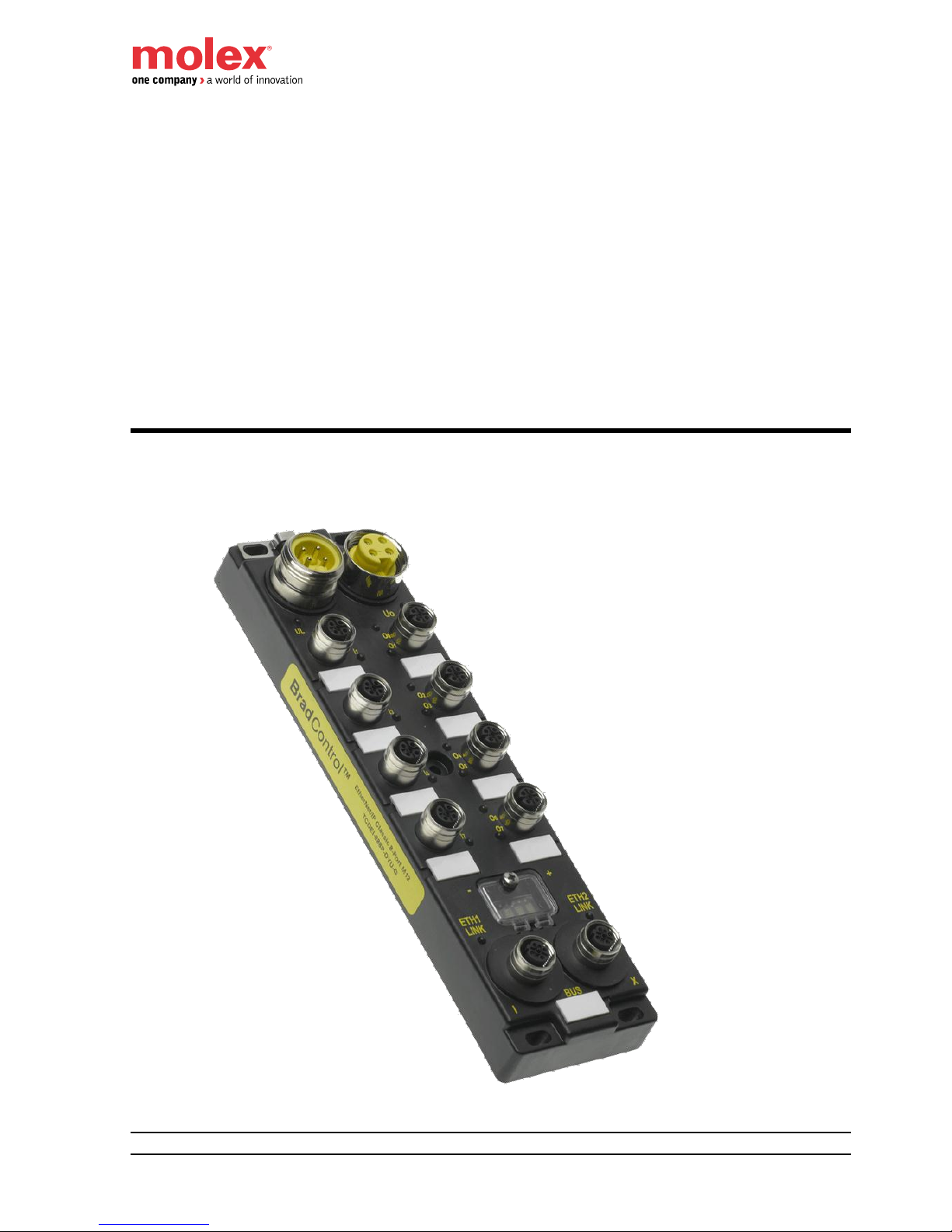
HarshIO 600 eIP
IP67 Digital I/O Modules for EtherNet/IP
Isolated Grounding and QuickConnect Versions
BradControl™ from Molex
Version 2.6
March 25th, 2013
Page 2
HarshIO 600 eIP
ii IP67 Digital I/O Modules for EtherNet/IP
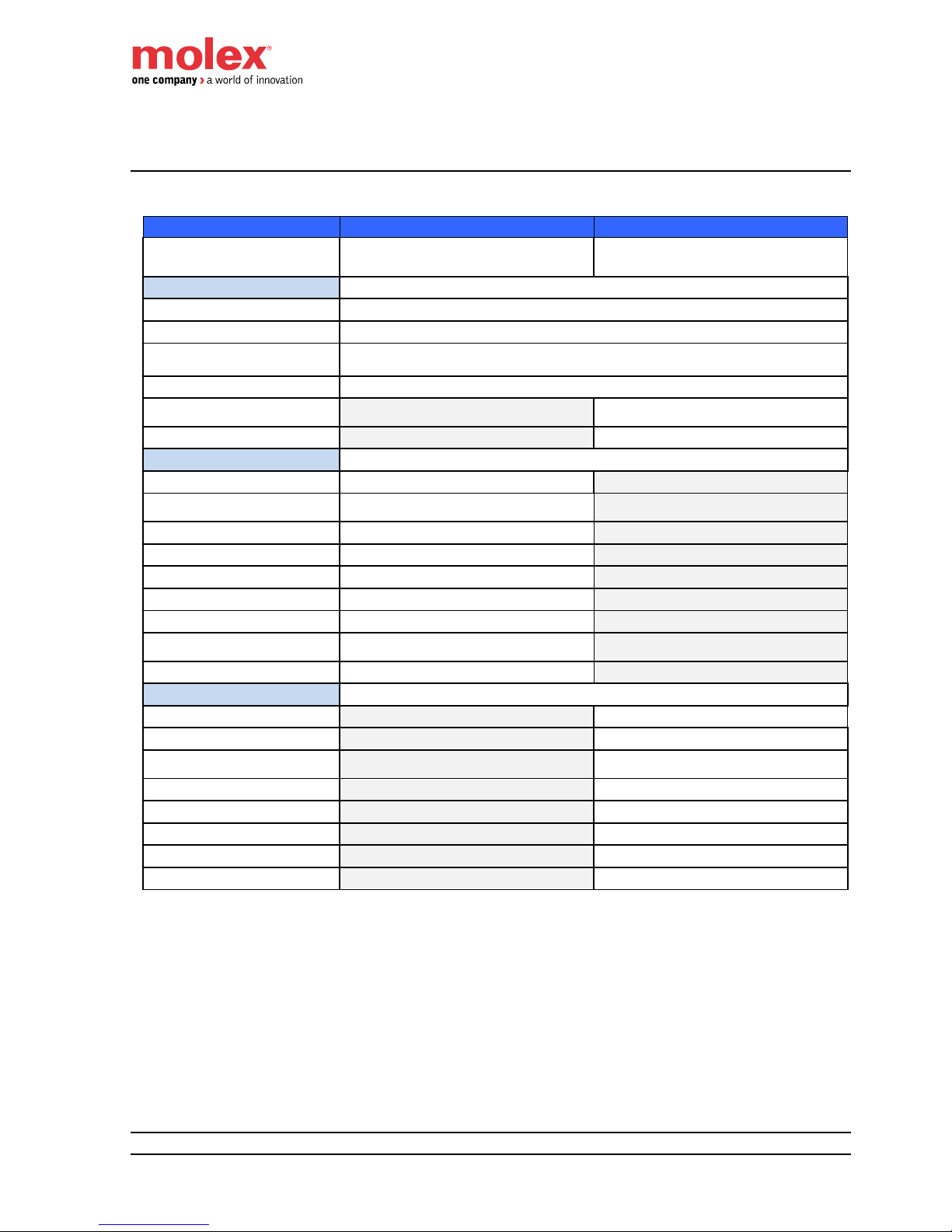
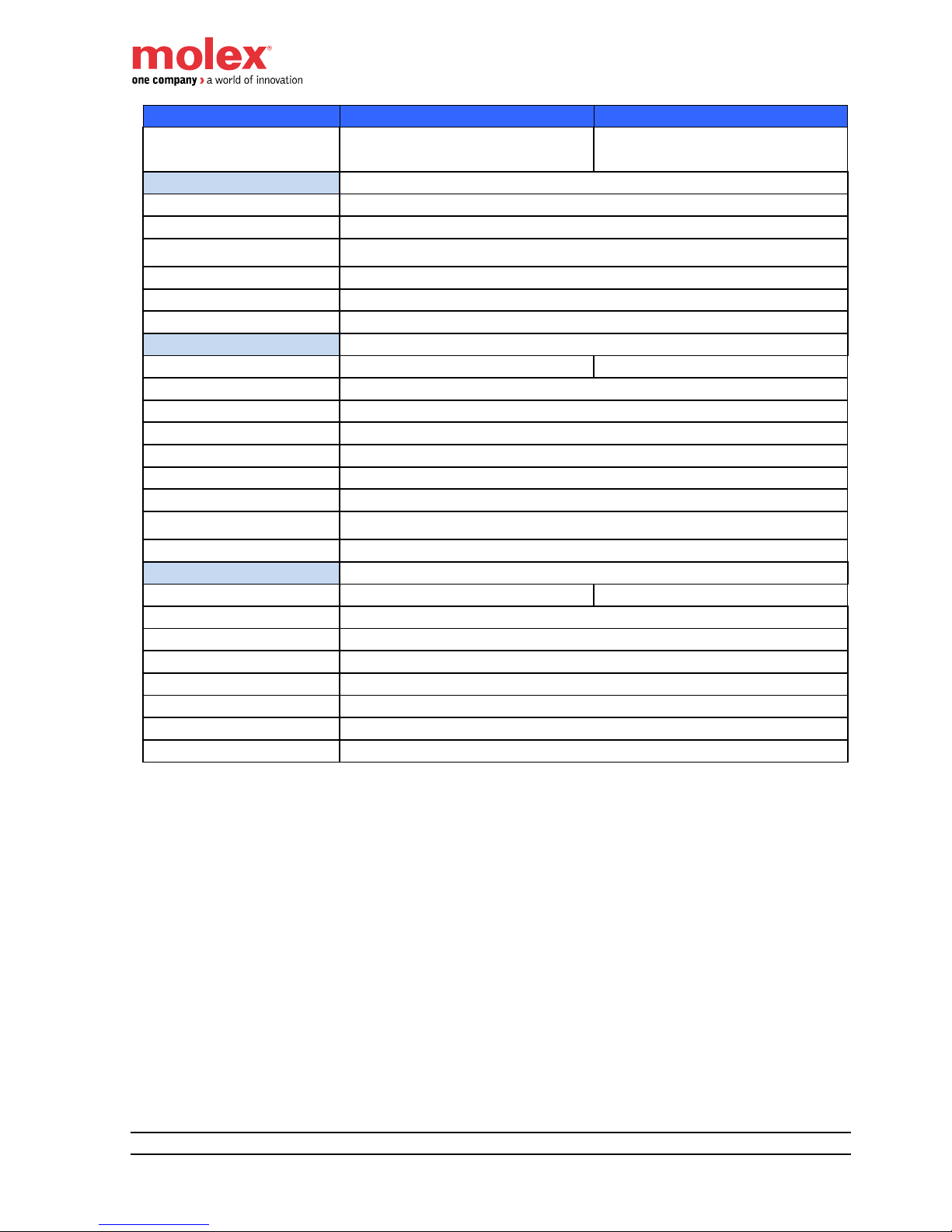
Revision History
Date
Author
Changes
Revision
January 24, 2012
E. GORY
Release version
1.0
February 06, 2012
E. GORY
Various typo corrections
Hyperlink to Molex Support and Download page
1.1
February 13, 2012
E. GORY
Various typo corrections
1.2
March 20, 2012
E. GORY
DHCP lease
1.3
September 06, 2012
E. GORY
Add 5-pin power supply module versions
Add 4-pin power 12IN/4OUT module version
2.0
September 14, 2012
E. GORY
Typo corrections
2.1
September 27, 2012
E. GORY
Typo corrections
2.2
December 11, 2012
E. GORY
Update mapping with power diagnostic bits
Add ground stub
Add EIP-Tool information and link
2.3
December 17, 2012
E. GORY
Correction 4-pin power supply wiring
Set Attribute 12 of CIP TCP/IP object (0xF5)
2.4
January 10, 2013
E. GORY
Update Listen Only (LO) connection information
2.5
March 25, 2013
E. GORY
Update default module settings
Add Chapter 9 - Web server interface
Update Chapter 8 for RXLogix 5000 v20
2.6
Although every effort has been made to ensure the accuracy of this document, all information is subject
to change without notice. Molex takes no liability for any errors in this document or for direct, indirect, or
consequential damage resulting from the use of this manual.
Page 3

HarshIO 600 eIP
iii IP67 Digital I/O Modules for EtherNet/IP
STATEMENT OF LIMITED WARRANTY
BradControl™ from Molex, manufacturer of HarshIO products, warrants to Buyer that products, except
software, manufactured by BradControl™ will be free from defects in material and workmanship.
BradControl™ obligation under this warranty will be limited to repairing or replacing the defective parts within
one year of the date of installation. Products may be returned by Buyer only after permission has been
obtained from BradControl™. Buyer will prepay all freight charges to return any products to the repair facility
designated by BradControl™.
BradControl™ further warrants that any software supplied as part of a product sale, except obsolete products,
will be free from non-conformances with BradControl™ published specifications for a period of 90 days from
the time of delivery. While BradControl™ endeavors to improve the features and performance of software
associated with its products, no effort on the part of BradControl™ to investigate, improve or modify HarshIO
modules firmware at the request of a customer will obligate BradControl™ in any way.
For the convenience of existing customers, BradControl™ continues to supply certain products that are
classified as obsolete. No warranty on the software features of these products is stated or implied and
BradControl™ specifically is not obligated to improve the design of these products in any way. Information
about the status of any product is available upon request and customers are advised to inquire about the
status of older products prior to making a purchase.
This limited warranty does not cover losses or damages which occur in shipment to or from Buyer or due to
improper installation, maintenance, misuse, neglect or any cause other than ordinary commercial or industrial
applications. In particular, BradControl™ makes no warranties whatsoever with respect to implied warranties
of merchantability or fitness for any particular purpose. All such warranties are hereby expressly disclaimed.
No oral or written information or advice given by BradControl™ or BradControl™'s representative shall create
a warranty or in any way increase the scope of this warranty. This limited warranty is in lieu of all other
warranties whether oral or written, expressed or implied. BradControl™’s liability shall not exceed the price of
the individual units, which are the basis of the claim. In no event shall BradControl™ be liable for any loss of
profits, loss of use of facilities or equipment, or other indirect, incidental or consequential damages.
Although every effort has been made to ensure the accuracy of this document, all information is subject to
change without any notice. BradControl™ takes no liability for any errors in this document or for direct, indirect,
or consequential damage resulting from the use of this manual.
The examples and diagrams in this manual are included solely for illustrative purposes. Because of the many
variables and requirements associated with any particular installation, BradControl™ cannot assume
responsibility or liability for actual use based on the examples and diagrams.
COPYRIGHTS and TRADEMARKS
Reproduction of the contents of this manual, in whole or in part, without written permission of BradControl™ is
prohibited.
Mini-Change®, Ultra-Lock™, BradControl™ are all registered trademarks of Molex, Inc.
All other products or trademarks are the property of their respective owners.
Page 4

HarshIO 600 eIP
iv IP67 Digital I/O Modules for EtherNet/IP
Table of contents
1. General Safety Instructions ................................................................ 6
General information ................................................................................................. 6
Personnel qualifications .......................................................................................... 6
Preventive messages .............................................................................................. 6
Usage compliance ................................................................................................... 6
Device installation and set-up ................................................................................. 7
Device operation ..................................................................................................... 8
Electrical, mechanical and thermal specifications ................................................... 8
Preventive and corrective maintenance .................................................................. 8
2. General Description ............................................................................. 9
Introduction .............................................................................................................. 9
3. System Description ........................................................................... 11
Overview ............................................................................................................... 11
Typical application ................................................................................................. 14
Quick Connect applications ................................................................................... 15
4. Module Characteristics ..................................................................... 18
Hardware characteristics ....................................................................................... 18
Mechanical characteristics .................................................................................... 22
Physical I/O mapping ............................................................................................ 23
I/O messaging ....................................................................................................... 27
I/O data mapping ................................................................................................... 28
Pin assignment ...................................................................................................... 36
Separate grounding wiring for application using safety relays .............................. 38
Port wiring type ...................................................................................................... 40
LED assignment .................................................................................................... 41
Network IP address setting ................................................................................... 42
Display information ................................................................................................ 45
Hardware address (MAC Address) ....................................................................... 46
EDS files ................................................................................................................ 46
5. Specific Behavior ............................................................................... 47
I/O behavior ........................................................................................................... 47
IDLE behavior ........................................................................................................ 47
Duplicate IP address ............................................................................................. 47
6. EtherNet/IP Object Classes ............................................................... 48
Identity (0x01) ........................................................................................................ 48
Message Router (0x02) ......................................................................................... 49
Assembly (0x04) .................................................................................................... 50
Connection Manager (0x06) .................................................................................. 51
TCP/IP Interface (0xF5) ........................................................................................ 52
Ethernet Link (0xF6) .............................................................................................. 53
7. Getting Started ................................................................................... 54
Packaging content ................................................................................................. 54
Accessories ........................................................................................................... 54
Getting Started ...................................................................................................... 55
Page 5

HarshIO 600 eIP
v IP67 Digital I/O Modules for EtherNet/IP
8. Configuration using RSLogix 5000 .................................................. 57
ESD File ................................................................................................................ 57
Commissionning HarshIO eIP in Rockwell Logix 5000 version 20 ....................... 58
Commissionning HarshIO eIP in Rockwell Logix 5000 version 17 ....................... 74
9. Web Server Interface ......................................................................... 76
IP and Physical information ................................................................................... 77
Network Interface information ............................................................................... 78
EtherNet/IP information ......................................................................................... 79
10. Earth Connection ............................................................................... 80
11. Cables and Cordsets ......................................................................... 82
Industrial Ethernet cables ...................................................................................... 82
I/O cables .............................................................................................................. 88
Power supply cables ............................................................................................. 94
12. Product Support ................................................................................ 96
Product Information ............................................................................................... 96
Technical Support ................................................................................................. 96
Page 6

HarshIO 600 eIP
6 IP67 Digital I/O Modules for EtherNet/IP
1. General Safety Instructions
General information
The current documentation is intended for persons technically qualified to install, use and service the
products described herein. It contains the necessary information for proper use of the products. However,
for advanced use of our products, please contact your nearest dealer for additional information.
The content of this documentation is not binding and cannot extend or limit warranties.
Personnel qualifications
Only qualified persons are authorized to install, use and service the products. Use by unqualified persons or
failure to follow the safety instructions of this document, the manuals and/or those affixed to the devices, can
result in irremediable harm or damage to persons and equipment. The following personnel are deemed to be
qualified persons for:
• Equipment operation: Personnel who operates the machines and/or processes connected to the
Brad™ products. Brad™ HarshIO must be used by persons who have received training and have
been informed of the major risks involved in working in an industrial environment.
• Preventive and corrective maintenance: Persons who modify Brad™ products hardware and software
configuration and install the product updates supplied by the manufacturer. These persons must:
o be trained in Brad™ products and operation and
o have the experience and technical knowledge required to be aware of the risks (electrical
hazards in particular) involved in their job and the ways of reducing these risks for themselves,
third parties and the equipment being used.
Preventive messages
Preventive messages are designed to identify the particular risks likely to affect personnel and/or hardware.
Different message types, both in the documentation and on the products, indicate different degrees of risk:
Danger messages indicate immediate hazards that could result in death or serious injury if not averted.
Warning messages indicate situations that could result in death, serious injury or material damage.
Caution messages indicate potentially dangerous situations that could cause bodily harm or material damage.
Usage compliance
The products described in the current documentation comply with currently applicable European
Directives (EC labeling). However, they can only operate correctly with the applications for which they were
Page 7

HarshIO 600 eIP
7 IP67 Digital I/O Modules for EtherNet/IP
intended as described in the documentation, and with approved products.
As a general rule, if all the handling, transportation, and storage recommendations and installation, operation
and maintenance instructions are followed, the products will operate correctly without risk for personnel or
hardware.
Device installation and set-up
It is important to follow the rules below when installing and setting up the Brad™ HarshIO. If system installation
includes products more than thirty meters away from each other, the basic cabling rules must be closely
followed.
• Strict compliance with the safety instructions provided in this documentation or on the equipment to be
installed and implemented, is absolutely essential.
• Make sure that the installation is carried out in compliance with regulations of the user country,
• Install the equipment in a suitable environment. As a closed equipment, the Brad™ HarshIO may be
installed in two ways:
o In a casing (cabinet, chest) or,
o Directly without any additional protection, if the associated systems (power supply, cables,
sensors, etc.) already carry a protection index equivalent to IP67 or higher.
Always connect the Brad™ HarshIO to the protective earth (PE) in compliance with existing standards
(for example: use the green/yellow wires in accordance with the NFC 15 100 standard).
• LV (Low Voltage) circuits must have a protective earth connection to ensure dangerous voltage
detection.
• Before powering up the device, check that the nominal voltage is the same as the mains voltage.
• Only use FELV (Functional Extra Low Voltage) power supplies which comply with existing standards.
• Check that the power voltages are within the tolerance ranges defined in the technical specifications
for the devices.
• Always ensure that power restoration (immediate, hot or cold) will not create a hazard for personnel or
equipment.
• Ensure that emergency stop devices remain effective in any equipment operation mode, even when
abnormal (for example, in the event of a cut wire). Resetting these devices should not result in
uncontrolled or undefined restarts.
• Position the signal cables so that the automation functions will not be disrupted by any capacitive,
inductive or electromagnetic influences, etc.
• Install the automation devices and their controlling devices so that they are protected against any
adverse incident.
• Adequate safety precautions must be applied to inputs and outputs to prevent the lack of signals from
causing undefined states in the automation devices.
Page 8

HarshIO 600 eIP
8 IP67 Digital I/O Modules for EtherNet/IP
Device operation
Because Brad™ HarshIO devices are components of a control system, the safety of the entire automated
system, including that of the installation and the application, cannot be dealt with in this document. For further
information, see IEC 1131-4, describing risk reduction measures for PLC users.
See the documentation of the specific products involved for more information on operation safety.
Electrical, mechanical and thermal specifications
Detailed information about the electrical, mechanical and thermal specifications of the device is available in the
associated technical documentation (installation manuals, service instructions).
Preventive and corrective maintenance
Servicing
• When replacing parts or components, only use factory approved parts.
• In all cases, before servicing a Brad™ HarshIO, disconnect the power supply from the device
(unplug the power cord or open the power cut-out device).
• Before servicing an onsite mechanical Brad™ HarshIO, disconnect its power supply and
mechanically lock the moving parts.
• On positive logic outputs or negative logic inputs, take all the necessary precautions to prevent
any disconnected wires from coming into contact with the mechanical ground (risk of unwanted
commands).
Product end-of-life
Contact your local dealer for information on how to dispose of used products in compliance with
current regulations.
Page 9
HarshIO 600 eIP
9 IP67 Digital I/O Modules for EtherNet/IP
2. General Description
Introduction
BradControl™ HarshIO eIP (EtherNet/IP) modules provide a reliable solution for connecting industrial
controllers to I/O devices in harsh duty environments. Contained in an IP67 rated housing, BradControl I/O
modules can be machine mounted and are able to withstand areas where liquids, dust or vibration may be
present. This makes them ideally suited for many applications including material handling equipment and
automated assembly machinery.
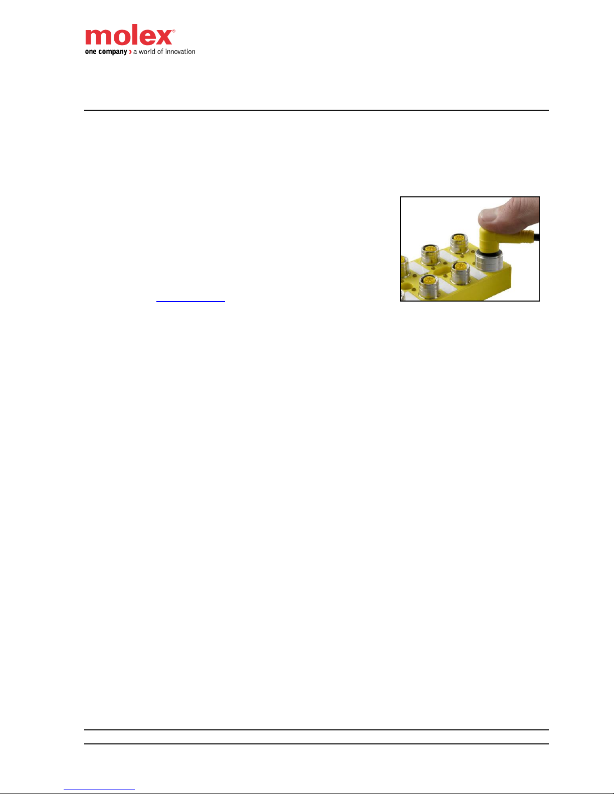
All BradControl™ HarshIO modules with Micro-Change® (M12)
ports accept both threaded cordsets and Molex Ultra-Lock™ system.
Ultra-Lock™ connection System! The fastest, easiest and most
secure connection ever designed. Ultra-Lock™ technology is designed
for higher performance and reliability. Discover how the push-to-lock
technology of the Ultra-Lock connection system can eliminate your
downtime, increase your productivity and lower your costs. More
information visit: www.molex.com .
BradControl™ HarshIO 600 includes advanced diagnostic features. Each module embeds visible LEDs
to provide for maintenance personnel the ability to easily determine I/O, module and network status. These
statuses are also available through the process data image or via extended slave diagnostics telegram.
BradControl™ HarshIO 600 main features include:
Module is housed in an IP67 rated enclosure that when properly installed—according to IEC
60529—provides protection against the ingress of dust, water
16x digital channels with up to 1ms I/O cycle time
Integrated 2-port unmanaged Ethernet switch with cross-over capability
Isolated grounding to able to use 2 separate power supplies to power the module logic/input
ground and the module output ground for safety application
Digital input and output short circuit protection
Quick Connect feature to power up and run the HarshIO module in less than 500ms for robotic
application where I/O are control on a tool changer
BradControl™ HarshIO 600 is available in various combinations:
16x Inputs
16x Outputs
8x Inputs + 8x Outputs
12x Inputs + 4x Outputs
Whatever the combination, the digital inputs and outputs are always PNP.
Page 10
HarshIO 600 eIP
10 IP67 Digital I/O Modules for EtherNet/IP
Part Number Table
4-pin power connector versions
SAP No
Material No
Description
112095-5040
TCDEI-8D0P-DYU-G
IP67 module for EtherNet/IP, 4-pin power supply connector,
16 PNP Inputs, Isolated grounding and QuickConnect
112095-5041
TCDEI-888P-DYU-G
IP67 module for EtherNet/IP, 4-pin power supply connector,
8 PNP Inputs + 8 Outputs, Isolated grounding and QuickConnect
112095-5043
TCDEI-8B4P-DYU-G
IP67 module for EtherNet/IP, 4-pin power supply connector,
12 PNP Inputs + 4 Outputs, Isolated grounding and QuickConnect
112095-5042
TCDEI-80DP-DYU-G
IP67 module for EtherNet/IP, 4-pin power supply connector,
16 Outputs, Isolated grounding and QuickConnect
5-pin power connector versions
SAP No
Material No
Description
112095-5060
TCDEI-8D0P-D1U-G
IP67 module for EtherNet/IP, 5-pin power supply connector,
16 PNP Inputs, Isolated grounding and QuickConnect
112095-5061
TCDEI-888P-D1U-G
IP67 module for EtherNet/IP, 5-pin power supply connector,
8 PNP Inputs + 8 Outputs, Isolated grounding and QuickConnect
112095-5063
TCDEI-8B4P-D1U-G
IP67 module for EtherNet/IP, 5-pin power supply connector,
12 PNP Inputs + 4 Outputs, Isolated grounding and QuickConnect
112095-5062
TCDEI-80DP-D1U-G
IP67 module for EtherNet/IP, 5-pin power supply connector,
16 Outputs, Isolated grounding and QuickConnect
Page 11
HarshIO 600 eIP
11 IP67 Digital I/O Modules for EtherNet/IP
3. System Description
Overview
HarshIO eIP modules can be used with a protocol compliant scanner as part of control system
architecture. The modules’ built-in unmanaged 2-port Ethernet switch allows you to use the network topology
that meets your application needs. These topologies include the following:
star
daisy-chain
combination of star and daisy-chain
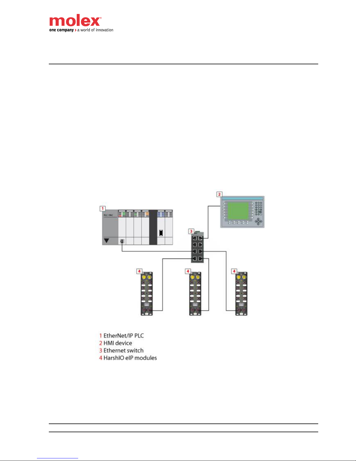
Star topology
Star topology allows you to connect mixed I/O modules or additional equipments. Performing
maintenance on one module – for example, by removing the network cable, or by cycling power to the
module – does not affect other modules.
Page 12
HarshIO 600 eIP
12 IP67 Digital I/O Modules for EtherNet/IP
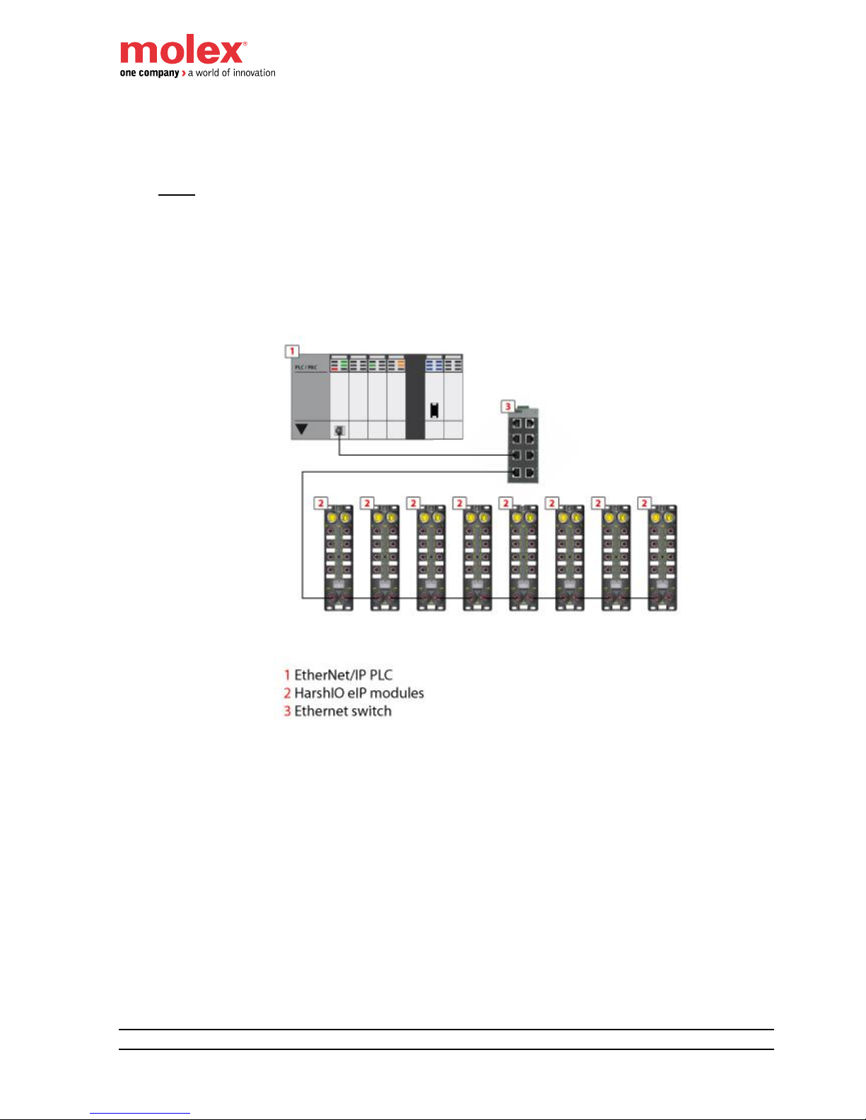
Daisy-chain topology
You can create a daisy-chain topology by using the module’s embedded switch ports to connect a series
of up to 8 HarshIO eIP modules.
NOTE: When considering the daisy chain topology, note that:
Performing maintenance on any module not physically located at the end of the daisy chain –
for example, by removing the network cable, or by cycling power to the module – affects any
modules located down the chain from the maintained module.
The embedded dual port Ethernet switch located in each module eliminates the need for
additional Ethernet switches.
Page 13
HarshIO 600 eIP
13 IP67 Digital I/O Modules for EtherNet/IP
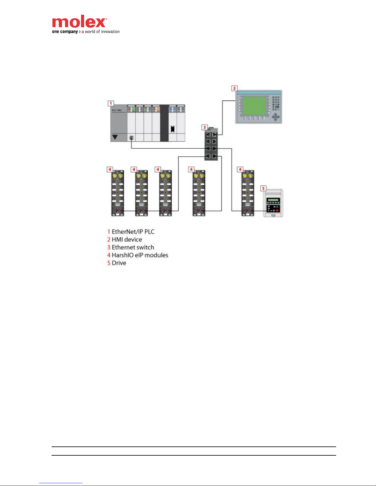
Combination of star and daisy-chain topology
Combining star and daisy-chain topology allows you to connect HarshIO eIP modules with mixed
HarshIO modules or additional equipments.
Page 14
HarshIO 600 eIP
14 IP67 Digital I/O Modules for EtherNet/IP
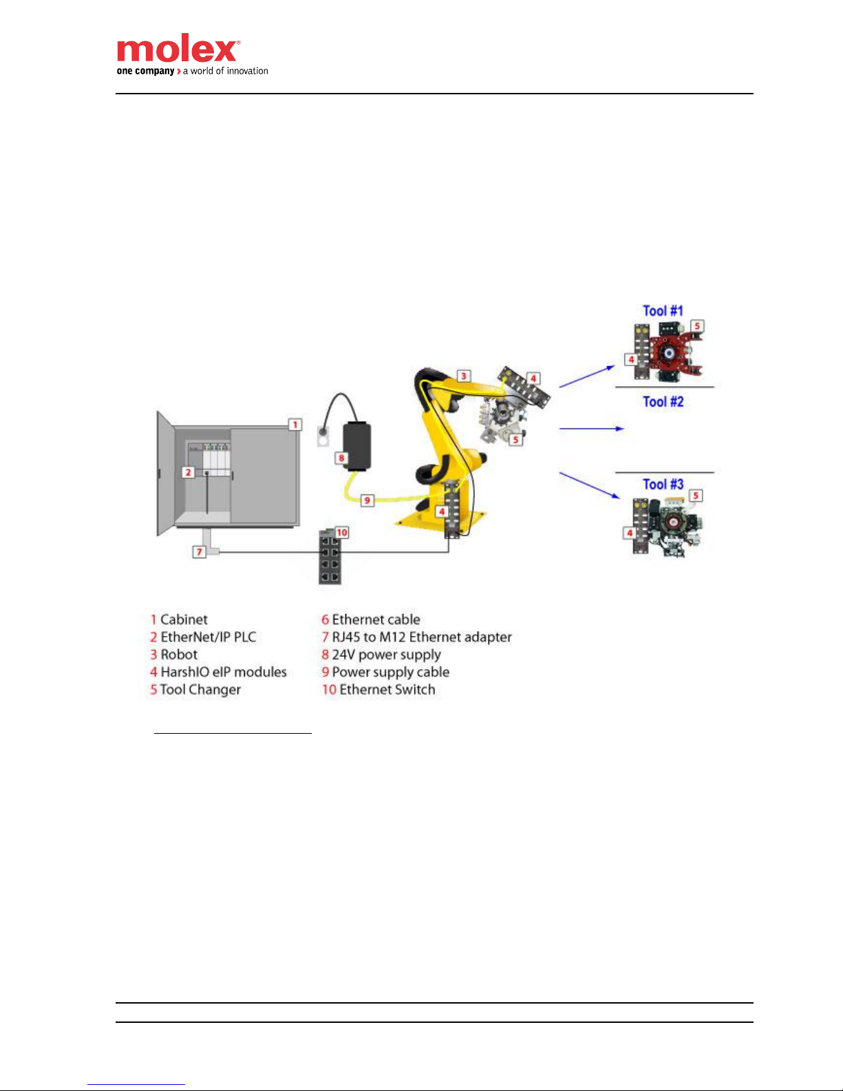
Typical application
This diagram shows you an example of a typical application using in-cabinet PLC controlling HarshIO
eIP modules mount on various industrial systems.
Page 15
HarshIO 600 eIP
15 IP67 Digital I/O Modules for EtherNet/IP
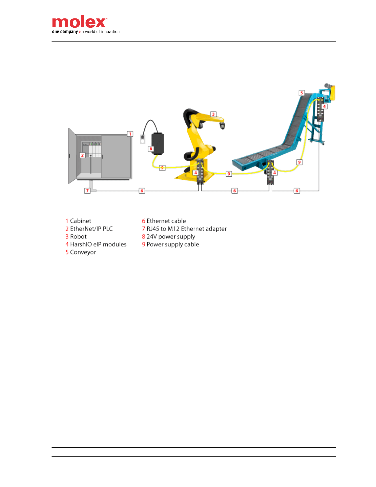
Quick Connect applications
The HarshIO eIP modules are designed to support the new Quick Connect feature according the
ODVA specifications which allow to power up, connect an EtherNet/IP scanner and start I/O cyclic data
exchange in less than 500 msec.
The Quick Connect feature is typically used in robotic application where some I/O devices are mounted
on a tool changer. The robot can disconnect and reconnect on the fly a new tool without stopping the
manufacturing process.
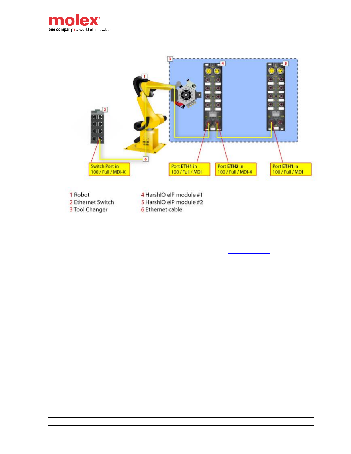
The diagram shows you an example of a robotic application using Quick Connect feature.
Quick Connect Architecture
When Quick Connect feature is used, the following recommendations should apply:
The Quick Connect device Ethernet switch ports must be configured with fixed speed to
100Mbps and full duplex enabled (auto negotiation is prohibited).
The Ethernet cable mounted on the robot must be connected to the ETH1 port (MDI port) of the
HarshIO eIP module. Quick Connect devices shall not use Auto-MDIX (detection of the required
cable connection type). This detection may take more time than the allowed Quick Connect
system connection time (see diagram below).
The maximum number of Quick Connect HarshIO eIP modules connected using daisy-chain
topology on the robot tool changer is recommended to be less or equal to 8. This limit can be
reduced depending of the Quick Connect performance supported by the EtherNet/IP controller.
Page 16
HarshIO 600 eIP
16 IP67 Digital I/O Modules for EtherNet/IP
Enabling Quick Connect mode
The HarshIO eIP modules can be configured for Quick Connect mode according the 2 methods:
1. Set Byte 9, Bit 0 of the configuration assembly (see chapter I/O Data Mapping).
- a value of “0” automatically
o disables Quick Connect
o sets ETH1 and ETH2 Ethernet ports to autonegociation and Auto-MDIX
- a value of “1” automatically
o enables Quick Connect
o sets ETH1 port to 100 Full Duplex MDI
o sets ETH2 port to 100 Full Duplex MDIX
2. Set Attribute 12 of CIP TCP/IP object (0xF5) using Explicit Messaging
- a value of “0” automatically
o disables Quick Connect
o sets ETH1 and ETH2 Ethernet ports to Auto-MDIX
- a value of “1” automatically
o enables Quick Connect
o sets ETH1 port to MDI
o sets ETH2 port to MDIX
Remember: Don’t forget also to force the ETH1/ETH2 ports speed to 100 Full Duplex
by setting to 1 the Attribute 6 of CIP Ethernet Link object (0xF6).
Page 17

HarshIO 600 eIP
17 IP67 Digital I/O Modules for EtherNet/IP
Caution: If method 2 is used, don’t forget to set to “0” the Configuration Assembly data
size (see chapter I/O Data Mapping) to avoid overwriting the Quick Connect Attribute
during the I/O connection with the EtherNet/IP scanner (Forward Open request).
Note: After each change of Quick Connect mode (means enable disable), the HarshIO module stores
the new requested mode in its non-volatile memory. The module behaves in this mode until the next
modification.
Note: The modification of a Quick Connect mode is applied after the next power supply cycling of the
module or by sending a Reset command (CIP object 0x01, Instance 1 Service 5).
Page 18
HarshIO 600 eIP
18 IP67 Digital I/O Modules for EtherNet/IP
4. Module Characteristics
Hardware characteristics
Type
16x INPUTS
16x OUTPUTS
Product Reference
TCDEI-8D0P-DYU-G (4-pin power version)
TCDEI-8D0P-D1U-G (5-pin power version)
TCDEI-80DP-DYU-G (4-pin power version)
TCDEI-80DP-D1U-G (5-pin power version)
Power Power IN connector
Mini Change (7/8”), 4-pin or 5-pin, male, stainless steel, Maximum 8 A
Power OUT connector
Mini Change (7/8”), 4-pin or 5-pin, female, stainless steel, Maximum 8 A
Module & Input power (UB)
24 VDC, -15/+20% (protected against power crossing).
Warning, a voltage over 30 VDC will destroy the module
Operating current (UB)
68 mA
Output power (UL)
Not Applicable
24 VDC, -15/+20%
(protected against power crossing)
Operating current (UL)
Not Applicable
10 mA (without load)
Inputs
Channels
16 channels, 2 or 3-wire
Not Applicable
Connector
M12 Ultra-Lock, 5-pin, female, A-Coded,
stainless steel
Not Applicable
Input type
PNP, Sinking
Not Applicable
Input voltage
UB
Not Applicable
Sensor power supply
140 mA at 25°C
Not Applicable
Input channel voltage (“1”)
10V … 30V
Not Applicable
Input channel voltage (“0”)
-0.2V … 5V
Not Applicable
Input short circuit
protection (per port)
600mA
Not Applicable
Input filter
1 … 5 ms (5 ms by default)
Not Applicable
Outputs
Channels
Not Applicable
16 channels, 2-wire
Output voltage
Not Applicable
UL -1 VDC
Connector
Not Applicable
M12 Ultra-Lock, 5-pin, female, A-Coded,
stainless steel
Output type
Not Applicable
PNP, Sourcing
Output current
Not Applicable
2 A per channel
Maximum output current
Not Applicable
8.0 A at 25°C ; total for all outputs combined
Short circuit current (typical)
Not Applicable
up to 6.5 A
Switching frequency
Not Applicable
200 Hz
Page 19
HarshIO 600 eIP
19 IP67 Digital I/O Modules for EtherNet/IP
Type
12x INPUTS + 4x OUTPUTS
8x INPUTS + 8x OUTPUTS
Product Reference
TCDEI-8B4P-DYU-G (4-pin power version)
TCDEI-8B4P-D1U-G (5-pin power version)
TCDEI-888P-DYU-G (4-pin power version)
TCDEI-888P-D1U-G (5-pin power version)
Power
Power IN connector
Mini Change (7/8”), 4-pin or 5-pin, male, stainless steel, Maximum 8 A
Power OUT connector
Mini Change (7/8”), 4-pin or 5-pin, female, stainless steel, Maximum 8 A
Module & Input power (UB)
24 VDC, -15/+20% (protected against power crossing)
Warning, a voltage over 30 VDC will destroy the module
Operating current (UB)
68 mA
Output power (UL)
24 VDC, -15/+20% (protected against power crossing)
Operating current (UL)
10 mA (without load)
Inputs
Channels
12 channels, 2 or 3-wire
8 channels, 2 or 3-wire
Connector
M12 Ultra-Lock, 5-pin, female, A-Coded, stainless steel
Input type
PNP, Sinking
Input voltage
UB
Sensor power supply
140 mA at 25°C
Input channel voltage (“1”)
10V … 30V
Input channel voltage (“0”)
-0.2V … 5V
Input short circuit
protection (per port)
600mA
Input filter
1 … 5 ms (5 ms by default)
Outputs
Channels
4 channels, 2-wire
8 channels, 2-wire
Output voltage
UL -1 VDC
Connector
M12 Ultra-Lock, 5-pin, female, A-Coded, stainless steel
Output type
PNP, Sourcing
Output current
2 A per channel
Maximum output current
8.0 A at 25°C ; total for all outputs combined
Short circuit current (typical)
up to 6.5 A
Switching frequency
200 Hz
Page 20
HarshIO 600 eIP
20 IP67 Digital I/O Modules for EtherNet/IP
Fieldbus Ethernet connectors
M12, 4-pin, female, D-Coded, stainless steel, shielded
IP setting
DHCP based on MAC (infinite lease), Static IP
Protocol
EtherNet/IP Adapter according specification Vol 1-3.9 (CIP) and Vol 2 – 1.10 (EtherNet/IP)
Data access
Implicit messages for I/O data transfer
Implicit (I/O) connection
1x Exclusive Owner (EO) connection (with or without configuration data)
Up to 7 Listen Only (LO) or Input Only (IO) connections (with or without configuration data)
Explicit (EM) connection
Up to 8
Supported CIP Objects
0x01 – Identity object
0x02 – Message Router object
0x04 – Assembly object
o 103: TO (Input process data)
o 104: OT (Output process data)
o 106: Configuration
o 198: OT Heartbeat (Input Only)
o 199: OT Heartbeat (Listen Only)
0x06 – Connection Manager object
0xF5 – TCP/IP Interface object
0xF6 – Ethernet Link object
Integrated Switch
2x ports integrated switch
Speed: 10/100Mbps
Auto negotiation
Auto crossing
Auto polarity
1x status Led / port
Storm Protection against network loop (Broadcast, Multicast and Unicast packets)
Daisy Chain (Ethernet)
Up to 8 HarshIO
Ethernet Packet
Manage up to 9000 packet/sec
Request Packet Interval (RPI)
from 1 ms up to 65535 ms (default 30 ms)
IP Address Conflict Detection
Yes (ACD supported)
Quick Connect
Yes (Class A)
ODVA conformance
Yes
Default IP setting:
IP address: DHCP
Subnet mask: DHCP
Gateway: DHCP
ETH1 port: Auto negotiation + Auto-MDI
ETH2 port: Auto negotiation + Auto-MDI
Quick Connect: Disabled
ACD Enabled
Page 21
HarshIO 600 eIP
21 IP67 Digital I/O Modules for EtherNet/IP
Mechanical
Housing dimension
600 x 220 x 20 mm (2.36"x8.66"x.780")
Housing material
PBT VALOX 420 SEO Black 7701
Flammability Standard
UL 94 V-0
Corner mounting hole
4 mounting holes, 5 x10 mm
Central mounting hole
1 mounting hole, 4.45 mm
Ground stud
Yes, stainless steel (allows the continuity of the ground when the module is mounted on the chassis
machine)
Operating temperature
-25°c … +70°c
Storage temperature
-40°c … +90°c
Vibration resistance
7G (15,7Hz to 500Hz), 3 axis
Shock resistance
15g, 11ms, 3 axis
Electro-magnetic compatibility
EN 61000-6-2 / EN 61000-6-4
Relative humidity
10 % to 95 %, non-condensing
Protection Class
IP67
Approval
CE (according IEC 61131-2), UL / cUL
Environmental
RoHS and REACH
MTBF
100 000 hours / 11 years at 70°C
Page 22

HarshIO 600 eIP
22 IP67 Digital I/O Modules for EtherNet/IP
Mechanical characteristics
Size and dimensions (in mm)
60,
0
220,0
20
,0
3
7,1
31
,5
38,
0
210,0
107
4,45
5x10
+
-
PE
Ui Uo
I 0
I 1
I 2
I 3
I 4
I 5
I 6
I 7
I 8
I 9
I 10
I 11
I 12
I 13
I 14
I 15
ETH1
LINK
ETH2
LINK
BUS
I
X
UL UB
Page 23
HarshIO 600 eIP
23 IP67 Digital I/O Modules for EtherNet/IP
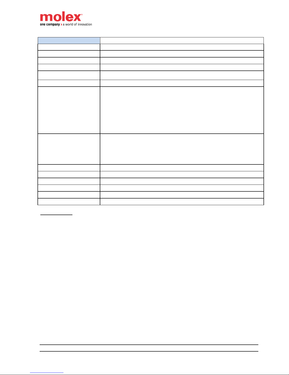
Physical I/O mapping
16x Inputs (4-pin power connector)
16x Inputs (5-pin power connector)
+
-
PE
Ui Uo
ETH1
LINK
ETH2
LINK
BUS
I
X
UL UB
I0
I1
I2
I3
I4
I5
I6
I7
I8
I9
I10
I11
I12
I13
I14
I15
+-
PE
Ui Uo
ETH1
LINK
ETH2
LINK
BUS
I X
UL UB
I0
I1
I2
I3
I4
I5
I6
I7
I8
I9
I10
I11
I12
I13
I14
I15
Page 24
HarshIO 600 eIP
24 IP67 Digital I/O Modules for EtherNet/IP
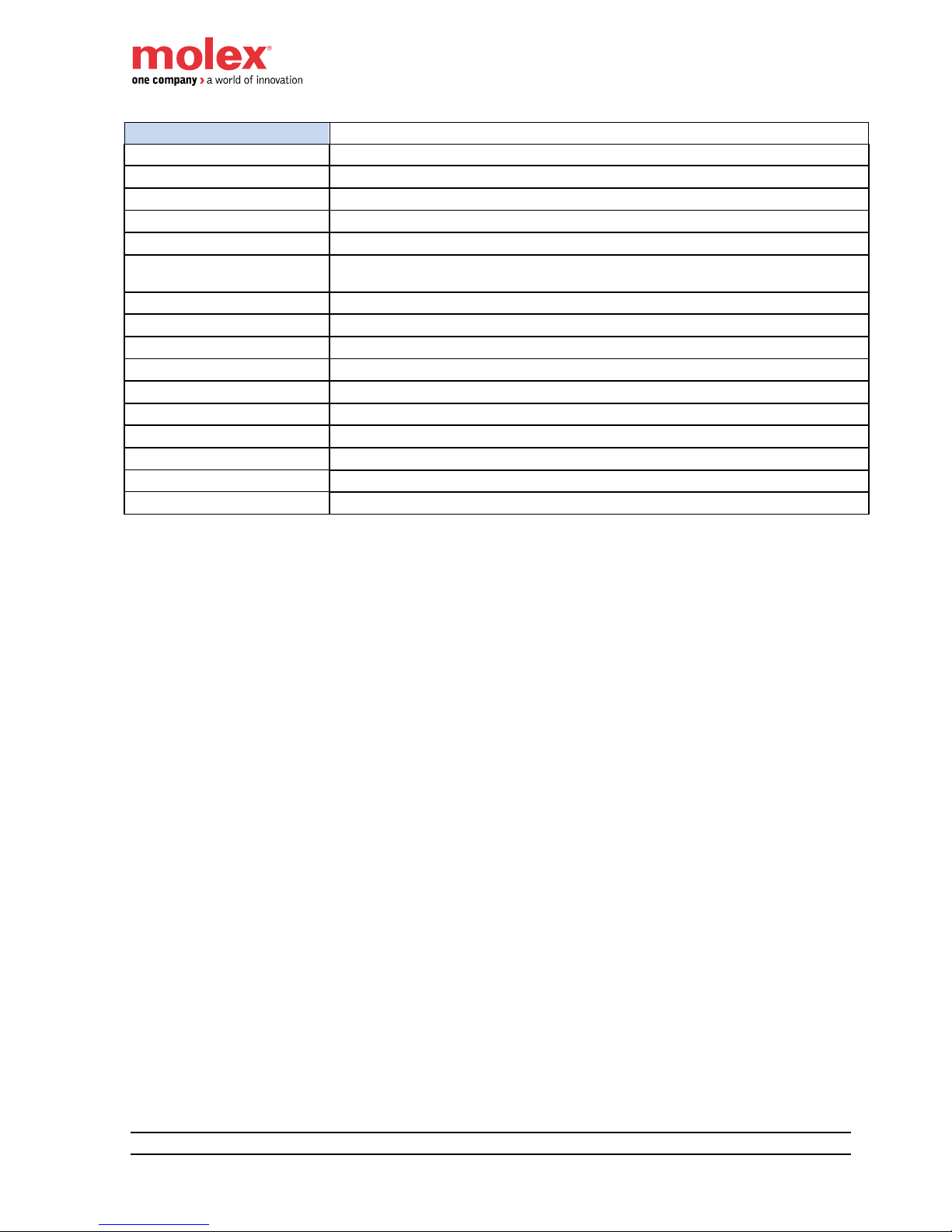
12x Inputs + 4x Outputs (4-pin power connector)
12x Inputs + 4x Outputs (5-pin power connector)
+
-
PE
Ui Uo
ETH1
LINK
ETH2
LINK
BUS
I
X
UL UB
I0
I1
I2
I
3
I4
I5
I6
I7
I8
I9
I10
I
11
O0
O1
O2
O3
+-
PE
Ui Uo
ETH1
LINK
ETH2
LINK
BUS
I X
UL UB
I0
I1
I2
I3
I4
I5
I6
I7
I8
I9
I10
I11
O0
O1
O2
O3
Page 25
HarshIO 600 eIP
25 IP67 Digital I/O Modules for EtherNet/IP
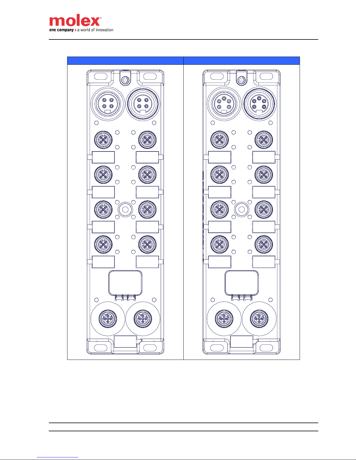
8x Inputs + 8x Outputs (4-pin power connector)
8x Inputs + 8x Outputs (5-pin power connector)
+
-
PE
Ui Uo
ETH1
LINK
ETH2
LINK
BUS
I
X
UL UB
I0
I1
I2
I3
I4
I5
I6
I7
O0
O1
O2
O3
O4
O5
O6
O7
+-
PE
Ui Uo
ETH1
LINK
ETH2
LINK
BUS
I X
UL UB
I0
I1
I2
I3
I4
I5
I6
I7
O0
O1
O2
O3
O4
O5
O6
O7
Page 26

HarshIO 600 eIP
26 IP67 Digital I/O Modules for EtherNet/IP
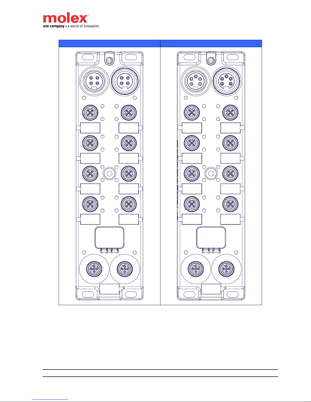
16x Outputs (4-pin power connector)
16x Outputs (5-pin power connector)
+
-
PE
Ui Uo
ETH1
LINK
ETH2
LINK
BUS
I
X
UL UB
O0
O1
O2
O3
O4
O5
O6
O7
O8
O9
O10
O11
O12
O13
O14
O15
+-
PE
Ui Uo
ETH1
LINK
ETH2
LINK
BUS
I X
UL UB
O0
O1
O2
O3
O4
O5
O6
O7
O8
O9
O10
O11
O12
O13
O14
O15
Page 27
HarshIO 600 eIP
27 IP67 Digital I/O Modules for EtherNet/IP
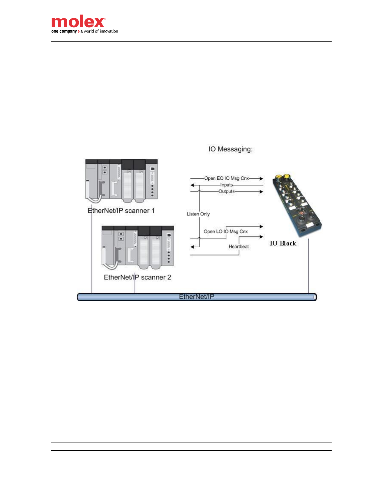
I/O messaging
The firmware embedded in the HarshIO 600 eIP supports up to a maximum of 8 I/O connections. Fewer
connections allow faster data I/O update rates (RPI value).
I/O Connections:
- Module supports 2 Transport Class 1 I/O connections (Cyclic and Change-Of-State triggers):
o 1x Exclusive Owner
Unicast and Multicast (TO) connection
Unicast (OT) connection
o 7x Listen Only or Input Only
Multicast (TO) connection
Page 28
HarshIO 600 eIP
28 IP67 Digital I/O Modules for EtherNet/IP
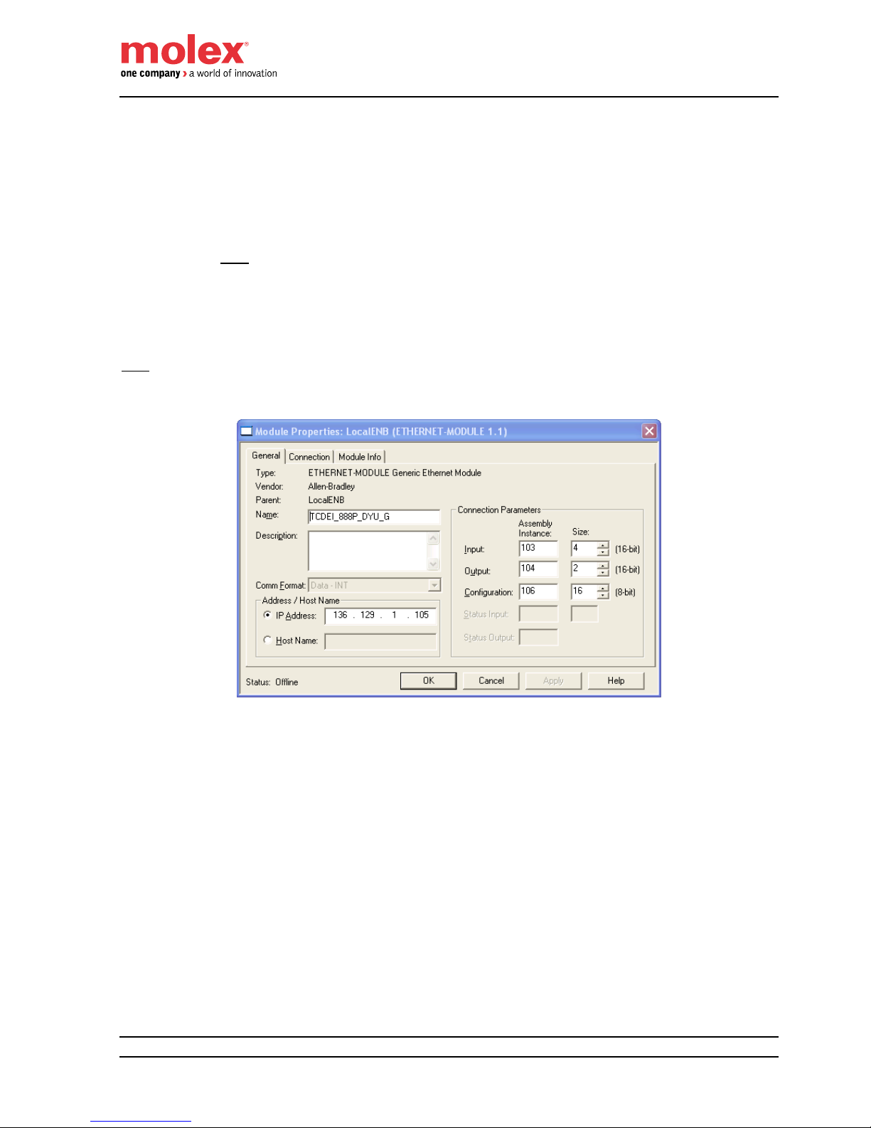
I/O data mapping
The I/O process data are available through the EtherNet/IP assemblies:
Assembly #103 for Input process data
Assembly #104 for Output process data
Assembly #106 for Configuration data
o Note: The data size can be set to “0” if the scanner doesn’t need to send Configuration data
at the establishment of the connection (Forward Open request).
Note: If your controller configuration software doesn’t support the management of EDS files, you may have to
configure manually the assembly numbers to access the process data.
– Example of HarshIO 8in/8Out assembly configuration
in Rockwell Automation RSLogix 5000 –
Page 29
HarshIO 600 eIP
29 IP67 Digital I/O Modules for EtherNet/IP
16 Inputs module versions
Byte
Offset
Bit 15
Bit 14
Bit 13
Bit 12
Bit 11
Bit 10
Bit 9
Bit 8
Bit 7
Bit 6
Bit 5
Bit 4
Bit 3
Bit 2
Bit 1
Bit 0
Input Data (Assembly #103), Size: 8 bytes
Data
00
n/u
n/u
n/u
n/u
n/u
n/u
Diag
UB
n/u
n/u
n/u
n/u
n/u
n/u
n/u
n/u
n/u
Input Data
02
I15
I14
I13
I12
I11
I10
I9
I8
I7
I6
I5
I4
I3
I2
I1
I0
Port Status
04
n/u
n/u
n/u
n/u
n/u
n/u
n/u
n/u
n/u
n/u
n/u
n/u
n/u
n/u
n/u
n/u
Port Status
06
n/u
n/u
n/u
n/u
n/u
n/u
n/u
n/u
PS P7
PS P6
PS P5
PS P4
PS P3
PS P2
PS P1
PS P0
Output data (Assembly #104), Size: 2 bytes
Output Data
00
n/u
n/u
n/u
n/u
n/u
n/u
n/u
n/u
n/u
n/u
n/u
n/u
n/u
n/u
n/u
n/u
Configuration (Assembly #106), Size: 16 bytes
Data
00
n/u
n/u
n/u
n/u
n/u
n/u
n/u
n/u
n/u
n/u
n/u
n/u
n/u
n/u
n/u
n/u
Data
02
n/u
n/u
n/u
n/u
n/u
n/u
n/u
n/u
n/u
n/u
n/u
n/u
n/u
n/u
n/u
n/u
Data
04
n/u
n/u
n/u
n/u
n/u
n/u
n/u
n/u
n/u
n/u
n/u
n/u
n/u
n/u
n/u
n/u
Data
06
n/u
n/u
n/u
n/u
n/u
n/u
n/u
n/u
n/u
n/u
n/u
n/u
n/u
n/u
n/u
n/u
Data
08
n/u
n/u
n/u
n/u
n/u
n/u
n/u
QC
n/u
n/u
n/u
n/u
n/u
n/u
n/u
n/u
Data
10
n/u
n/u
n/u
n/u
n/u
n/u
n/u
n/u
n/u
n/u
n/u
n/u
n/u
n/u
n/u
n/u
Data
12
n/u
n/u
n/u
n/u
n/u
n/u
n/u
n/u
n/u
n/u
n/u
n/u
n/u
n/u
n/u
n/u
Data
14
n/u
n/u
n/u
n/u
n/u
n/u
n/u
n/u
n/u
n/u
n/u
n/u
n/u
n/u
n/u
n/u
n/u: Not used
Ix: Input channel x
PS: Port Status (short circuit detected on a port driving Input channels)
QC: Quick Connect, 1 = Enable; 0 = Disable
Diag UB: Diagnostic Logic/Input power supply (UB)
Set to 1, if UB is < 14.1 VDC
o All Outputs activated are de-energized
o All Outputs activated have diagnostic leds to RED
o All Outputs activated have Port Status (CS Ox) bit set to 1
Set to 0, if UB is > 14.6 VDC
o All Outputs activated are energized
o All Outputs activated have diagnostic leds to GREEN
o All Outputs activated have Port Status (CS Ox) bit set to 0
Page 30
HarshIO 600 eIP
30 IP67 Digital I/O Modules for EtherNet/IP
16 Outputs module versions
Byte
Offset
Bit 15
Bit 14
Bit 13
Bit 12
Bit 11
Bit 10
Bit 9
Bit 8
Bit 7
Bit 6
Bit 5
Bit 4
Bit 3
Bit 2
Bit 1
Bit 0
Input Data (Assembly #103), Size: 8 bytes
Data
00
n/u
n/u
n/u
n/u
n/u
n/u
Diag
UB
n/u
Diag
UL
n/u
n/u
n/u
n/u
n/u
n/u
n/u
Input Data
02
n/u
n/u
n/u
n/u
n/u
n/u
n/u
n/u
n/u
n/u
n/u
n/u
n/u
n/u
n/u
n/u
Port Status
04
CS O7
CS O6
CS O5
CS O4
CS O3
CS O2
CS O1
CS O0
n/u
n/u
n/u
n/u
n/u
n/u
n/u
n/u
Port Status
06
n/u
n/u
n/u
n/u
n/u
n/u
n/u
n/u
CS
O15
CS
O14
CS
O13
CS
O12
CS
O11
CS
O10
CS
O9
CS
O8
Output data (Assembly #104), Size: 4 bytes
00
n/u
n/u
n/u
n/u
n/u
n/u
n/u
n/u
n/u
n/u
n/u
n/u
n/u
n/u
n/u
n/u
Output Data
02
O15
O14
O13
O12
O11
O10
O9
O8
O7
O6
O5
O4
O3
O2
O1
O0
Configuration (Assembly #106), Size: 16 bytes
Data
00
n/u
n/u
n/u
n/u
n/u
n/u
n/u
n/u
n/u
n/u
n/u
n/u
n/u
n/u
n/u
n/u
Data
02
n/u
n/u
n/u
n/u
n/u
n/u
n/u
n/u
n/u
n/u
n/u
n/u
n/u
n/u
n/u
n/u
Data
04
n/u
n/u
n/u
n/u
n/u
n/u
n/u
n/u
n/u
n/u
n/u
n/u
n/u
n/u
n/u
n/u
Data
06
n/u
n/u
n/u
n/u
n/u
n/u
n/u
n/u
n/u
n/u
n/u
n/u
n/u
n/u
n/u
n/u
Data
08
n/u
n/u
n/u
n/u
n/u
n/u
n/u
QC
n/u
n/u
n/u
n/u
n/u
n/u
n/u
n/u
Data
10
n/u
n/u
n/u
n/u
n/u
n/u
n/u
n/u
n/u
n/u
n/u
n/u
n/u
n/u
n/u
n/u
Data
12
n/u
n/u
n/u
n/u
n/u
n/u
n/u
n/u
n/u
n/u
n/u
n/u
n/u
n/u
n/u
n/u
Data
14
n/u
n/u
n/u
n/u
n/u
n/u
n/u
n/u
n/u
n/u
n/u
n/u
n/u
n/u
n/u
n/u
n/u: Not used
CS: Channel status (short circuit on Output channel or impossible to drive the Output)
If output power supply (UL) is down, output channel status (CS) is set for the corresponding activated
output channels. The module display shows the message:”IO: ERR”.
Example: if the output “O3” is active and UL goes down, the “CS O3” status bit is set to 1.
Ox: Output channel x
QC: Quick Connect, 1 = Enable; 0 = Disable
Diag UB: Diagnostic Logic/Input power supply (UB)
Set to 1, if UB is < 14.1 VDC
o All Outputs activated are de-energized
o All Outputs activated have diagnostic leds to RED
o All Outputs activated have Port Status (CS Ox) bit set to 1
Set to 0, if UB is > 14.6 VDC
o All Outputs activated are energized
o All Outputs activated have diagnostic leds to GREEN
o All Outputs activated have Port Status (CS Ox) bit set to 0
Diag UL: Diagnostic Output power supply (UL)
Set to 1, if UL is < 17.6 VDC
o All Outputs activated are de-energized
o All Outputs activated have diagnostic leds to RED
Page 31

HarshIO 600 eIP
31 IP67 Digital I/O Modules for EtherNet/IP
o All Outputs activated have Port Status (CS Ox) bit set to 1
Set to 0, if UL is > 18.1 VDC
o All Outputs activated are energized
o All Outputs activated have diagnostic leds to GREEN
o All Outputs activated have Port Status (CS Ox) bit set to 0
Page 32

HarshIO 600 eIP
32 IP67 Digital I/O Modules for EtherNet/IP
12 Inputs + 4 Outputs module versions
Byte
Offset
Bit 15
Bit 14
Bit 13
Bit 12
Bit 11
Bit 10
Bit 9
Bit 8
Bit 7
Bit 6
Bit 5
Bit 4
Bit 3
Bit 2
Bit 1
Bit 0
Input Data (Assembly #103), Size: 8 bytes
Data
00
n/u
n/u
n/u
n/u
n/u
n/u
Diag
UB
n/u
Diag
UL
n/u
n/u
n/u
n/u
n/u
n/u
n/u
Input Data
02
n/u
n/u
n/u
n/u
I11
I10
I9
I8
I7
I6
I5
I4
I3
I2
I1
I0
Port Status
04
n/u
n/u
n/u
n/u
n/u
n/u
n/u
n/u
n/u
n/u
n/u
n/u
n/u
n/u
n/u
n/u
Port Status
06
n/u
n/u
n/u
n/u
CS O3
CS O2
CS O1
CS O0
n/u
n/u
PS P5
PS P4
PS P3
PS P2
PS P1
PS P0
Output data (Assembly #104), Size: 4 bytes
00
n/u
n/u
n/u
n/u
n/u
n/u
n/u
n/u
n/u
n/u
n/u
n/u
n/u
n/u
n/u
n/u
Output Data
02
n/u
n/u
n/u
n/u
n/u
n/u
n/u
n/u
n/u
n/u
n/u
n/u
O3
O2
O1
O0
Configuration (Assembly #106), Size: 16 bytes
Data
00
n/u
n/u
n/u
n/u
n/u
n/u
n/u
n/u
n/u
n/u
n/u
n/u
n/u
n/u
n/u
n/u
Data
02
n/u
n/u
n/u
n/u
n/u
n/u
n/u
n/u
n/u
n/u
n/u
n/u
n/u
n/u
n/u
n/u
Data
04
n/u
n/u
n/u
n/u
n/u
n/u
n/u
n/u
n/u
n/u
n/u
n/u
n/u
n/u
n/u
n/u
Data
06
n/u
n/u
n/u
n/u
n/u
n/u
n/u
n/u
n/u
n/u
n/u
n/u
n/u
n/u
n/u
n/u
Data
08
n/u
n/u
n/u
n/u
n/u
n/u
n/u
QC
n/u
n/u
n/u
n/u
n/u
n/u
n/u
n/u
Data
10
n/u
n/u
n/u
n/u
n/u
n/u
n/u
n/u
n/u
n/u
n/u
n/u
n/u
n/u
n/u
n/u
Data
12
n/u
n/u
n/u
n/u
n/u
n/u
n/u
n/u
n/u
n/u
n/u
n/u
n/u
n/u
n/u
n/u
Data
14
n/u
n/u
n/u
n/u
n/u
n/u
n/u
n/u
n/u
n/u
n/u
n/u
n/u
n/u
n/u
n/u
n/u: Not used
Ix: Input channel x
Ox: Output channel x
PS: Input Port Status (short circuit on Input channel)
CS: Channel status (short circuit on Output channel or impossible to drive the Output)
If output power supply (UL) is down, output channel status (CS) is set for the corresponding activated
output channels. The module display shows the message:”IO: ERR”.
Example: if the output “O3” is active and UL goes down, the “CS O3” status bit is set to 1.
QC: Quick Connect, 1 = Enable; 0 = Disable
Diag UB: Diagnostic Logic/Input power supply (UB)
Set to 1, if UB is < 14.1 VDC
o All Outputs activated are de-energized
o All Outputs activated have diagnostic leds to RED
o All Outputs activated have Port Status (CS Ox) bit set to 1
Set to 0, if UB is > 14.6 VDC
o All Outputs activated are energized
o All Outputs activated have diagnostic leds to GREEN
o All Outputs activated have Port Status (CS Ox) bit set to 0
Page 33

HarshIO 600 eIP
33 IP67 Digital I/O Modules for EtherNet/IP
Diag UL: Diagnostic Output power supply (UL)
Set to 1, if UL is < 17.6 VDC
o All Outputs activated are de-energized
o All Outputs activated have diagnostic leds to RED
o All Outputs activated have Port Status (CS Ox) bit set to 1
Set to 0, if UL is > 18.1 VDC
o All Outputs activated are energized
o All Outputs activated have diagnostic leds to GREEN
o All Outputs activated have Port Status (CS Ox) bit set to 0
Page 34

HarshIO 600 eIP
34 IP67 Digital I/O Modules for EtherNet/IP
8 Inputs + 8 Outputs module versions
Byte
Offset
Bit 15
Bit 14
Bit 13
Bit 12
Bit 11
Bit 10
Bit 9
Bit 8
Bit 7
Bit 6
Bit 5
Bit 4
Bit 3
Bit 2
Bit 1
Bit 0
Input Data (Assembly #103), Size: 8 bytes
Data
00
n/u
n/u
n/u
n/u
n/u
n/u
Diag
UB
n/u
Diag
UL
n/u
n/u
n/u
n/u
n/u
n/u
n/u
Input Data
02
n/u
n/u
n/u
n/u
n/u
n/u
n/u
n/u
I7
I6
I5
I4
I3
I2
I1
I0
Port Status
04
n/u
n/u
n/u
n/u
n/u
n/u
n/u
n/u
n/u
n/u
n/u
n/u
n/u
n/u
n/u
n/u
Port Status
06
CS O7
CS O6
CS O5
CS O4
CS O3
CS O2
CS O1
CS O0
n/u
n/u
n/u
n/u
PS P3
PS P2
PS P1
PS P0
Output data (Assembly #104), Size: 4 bytes
00
n/u
n/u
n/u
n/u
n/u
n/u
n/u
n/u
n/u
n/u
n/u
n/u
n/u
n/u
n/u
n/u
Output Data
02
n/u
n/u
n/u
n/u
n/u
n/u
n/u
n/u
O7
O6
O5
O4
O3
O2
O1
O0
Configuration (Assembly #106), Size: 16 bytes
Data
00
n/u
n/u
n/u
n/u
n/u
n/u
n/u
n/u
n/u
n/u
n/u
n/u
n/u
n/u
n/u
n/u
Data
02
n/u
n/u
n/u
n/u
n/u
n/u
n/u
n/u
n/u
n/u
n/u
n/u
n/u
n/u
n/u
n/u
Data
04
n/u
n/u
n/u
n/u
n/u
n/u
n/u
n/u
n/u
n/u
n/u
n/u
n/u
n/u
n/u
n/u
Data
06
n/u
n/u
n/u
n/u
n/u
n/u
n/u
n/u
n/u
n/u
n/u
n/u
n/u
n/u
n/u
n/u
Data
08
n/u
n/u
n/u
n/u
n/u
n/u
n/u
QC
n/u
n/u
n/u
n/u
n/u
n/u
n/u
n/u
Data
10
n/u
n/u
n/u
n/u
n/u
n/u
n/u
n/u
n/u
n/u
n/u
n/u
n/u
n/u
n/u
n/u
Data
12
n/u
n/u
n/u
n/u
n/u
n/u
n/u
n/u
n/u
n/u
n/u
n/u
n/u
n/u
n/u
n/u
Data
14
n/u
n/u
n/u
n/u
n/u
n/u
n/u
n/u
n/u
n/u
n/u
n/u
n/u
n/u
n/u
n/u
n/u: Not used
Ix: Input channel x
Ox: Output channel x
PS: Input Port Status (short circuit on Input channel)
CS: Channel status (short circuit on Output channel or impossible to drive the Output)
If output power supply (UL) is down, output channel status (CS) is set for the corresponding activated
output channels. The module display shows the message:”IO: ERR”.
Example: if the output “O3” is active and UL goes down, the “CS O3” status bit is set to 1.
QC: Quick Connect, 1 = Enable; 0 = Disable
Diag UB: Diagnostic Logic/Input power supply (UB)
Set to 1, if UB is < 14.1 VDC
o All Outputs activated are de-energized
o All Outputs activated have diagnostic leds to RED
o All Outputs activated have Port Status (CS Ox) bit set to 1
Set to 0, if UB is > 14.6 VDC
o All Outputs activated are energized
o All Outputs activated have diagnostic leds to GREEN
o All Outputs activated have Port Status (CS Ox) bit set to 0
Page 35

HarshIO 600 eIP
35 IP67 Digital I/O Modules for EtherNet/IP
Diag UL: Diagnostic Output power supply (UL)
Set to 1, if UL is < 17.6 VDC
o All Outputs activated are de-energized
o All Outputs activated have diagnostic leds to RED
o All Outputs activated have Port Status (CS Ox) bit set to 1
Set to 0, if UL is > 18.1 VDC
o All Outputs activated are energized
o All Outputs activated have diagnostic leds to GREEN
o All Outputs activated have Port Status (CS Ox) bit set to 0
Page 36

HarshIO 600 eIP
36 IP67 Digital I/O Modules for EtherNet/IP
Pin assignment
4-pin power supply versions
1
4
2
3
5
4
31
2
Power IN
4-pole, 7/8 (Mini-Change), Male
I/O Ports
5-pole, M12 (Micro-Change),
Female, A-Code
Power OUT
4-pole, 7/8 (Mini-Change), Female
Wiring Information:
1 - 24 VDC (Outputs Power)
2 - 24 VDC (Module & Inputs Power)
3 - 0 V (Ground Module & Inputs Power)
4 - 0 V (Outputs Power)
Wiring Information:
1 - +24 VDC
2 - B Input / Output
3 - 0 V (Ground)
4 - A Input / Output
5 - PE (Protected Earth)
2
3
4
1
PE
Wiring Information:
1 -TX+
2 - RX+
3 -TX4 - RX-
Ethernet Port 1 (ETH1)
4-pole, M12(Micro-Change),
Female, D-Code
Ethernet Port 2 (ETH2)
4-pole, M12(Micro-Change),
Female, D-Code
3
2
1
4
PE
PE
2
13
4
+
-
PE
Ui Uo
I 0
I 1
I 2
I 3
I 4
I 5
I 6
I 7
I 8
I 9
I 10
I 11
I 12
I 13
I 14
I 15
ETH1
LINK
ETH2
LINK
BUS
I
X
UL UB
Page 37

HarshIO 600 eIP
37 IP67 Digital I/O Modules for EtherNet/IP
5-pin power supply versions
Wiring Information:
1 - 0 V (Outputs Power)
2 - 0 V (Module & Inputs Power)
3 - PE (Protected Earth)
4 - 24 VDC (Module & Inputs Power)
5 - 24 VDC (Outputs Power)
1
4
2
3
5
Input Ports
5-pole, M12 (Micro-Change),
Female, A-Code
Wiring Information:
1 - +24 VDC
2 - Input (even)
3 - 0 V (Ground)
4 - Input (odd)
5 - PE (Protected Earth)
2
3
4
1
PE
Wiring Information:
1 -TX+
2 - RX+
3 -TX4 - RX-
Ethernet Port 1 (ETH1)
4-pole, M12(Micro-Change),
Female, D-Code
Ethernet Port 2 (ETH2)
4-pole, M12(Micro-Change),
Female, D-Code
3
2
1
4
PE
PE
1
4
2
3
5
Output Ports
5-pole, M12 (Micro-Change),
Female, A-Code
Wiring Information:
1 - n/c
2 - Output (even)
3 - 0 V (Ground)
4 - Output (odd)
5 - PE (Protected Earth)
1
2
3
4
5
Power IN
5-pole, 7/8 (Mini-Change), Male
1
2
3
4
5
Power OUT
5-pole, 7/8 (Mini-Change), Female
+
-
PE
Ui Uo
I0
I1
I2
I3
I4
I5
I6
I7
O0
O1
O2
O3
O4
O5
O6
O7
ETH1
LINK
ETH2
LINK
BUS
I
X
UL UB
Page 38

HarshIO 600 eIP
38 IP67 Digital I/O Modules for EtherNet/IP
Separate grounding wiring for application using safety relays
The HarshIO 600 power connector includes a separate grounding isolation between the input/logic
ground and the output ground. This feature allows powering the module with 2 distinct power supplies that is
commonly used in safety application.
Typically in automation application, a system designer is using safety relays (like Rockwell Automation
Guard I/O EtherNet/IP Safety Modules [1791ES-IB8XOBV4, 1791ES-IB16], Siemens PM-E F pp DC24V
[6ES7 138-4CF42-0AB0], Siemens PM-E F pm DC24V [6ES7 138-4CF03-0AB0]) that regularly perform the
pulse test to be able to detect a short-circuit, ground fault or an earth fault. If an error is detected the safety
function is triggered and unwanted and dangerous plant conditions are therefore avoided.
Architecture using 2 distinct grounds with safety relay
Page 39

HarshIO 600 eIP
39 IP67 Digital I/O Modules for EtherNet/IP
However if the separate grounding for safety is not required by the system designer, the HarshIO
modules can operate using a single ground for both logic/input and output.
Architecture using a single ground
Note, the connection of the common ground (Logic/Input + Output) is made outside the HarshIO
module.
Page 40

HarshIO 600 eIP
40 IP67 Digital I/O Modules for EtherNet/IP
Port wiring type
2 Input channels per port – Twin wired
2 Output channels per port – Twin wired
Note:
PNP wiring with a 2 wires input sensor
Connect pin 1 (24 V) and pin 4 or 2 (signal in)
Page 41

HarshIO 600 eIP
41 IP67 Digital I/O Modules for EtherNet/IP
+
-
PE
Ui Uo
ETH1
LINK
ETH2
LINK
BUS
I
X
UL UB
I0
I1
I2
I3
I4
I5
I6
I7
I8
I9
I10
I11
O0
O1
O2
O3
LED assignment
Quick Connect feature
In case of using Quick Connect mode, it
is mandatory
to connect the Ethernet cable
coming from the arm of the robot to
port ETH1
to connect a second module using
daisy chain topoology to port ETH2
Outputs Power LED (UL)
Green: Auxiliary Power supplied
Off: Auxiliary Power not supplied
Note: The outputs of the module operate
only if the LED is ON
16x Channel LED
Green: I/O Signal active
Off: I/O Signal not active
Red: Fault. Need Diagnostics
2x Ethernet Link Diagnostic LED
Green: 100 Mbps
Solid On: link without activity
Blink: link with activity
Yellow: 10 Mbps
Solid On: link without activity
Blink: link with activity
Module & Inputs power LED (UB)
Green: Auxiliary Power supplied
Off: Auxiliary Power not supplied
Scrolling digit display
IP address
I/O Fault
EtherNet/IP Status
IP Setting Push Buttons
Push button for IP Address mode and
setting
Quick Connect feature
In case of using Quick Connect, it is
mandatory to connect the port ETH2 to
the Ethernet cable going to an additional
HarshIO module mounted on the tool
changer.
In-coming Bus Power Connector (Ui)
Use this connector to power the module.
Out-coming Bus Power Connector (Uo)
Use this connector to daisy-chain the
power to an additional HarshIO eIP
module
9 Plastic labels
Available to write user information
Page 42

HarshIO 600 eIP
42 IP67 Digital I/O Modules for EtherNet/IP
Network IP address setting
The HarshIO 600 eIP is configured in DHCP mode by default. When connecting to a network with a DHCP
server, an IP address is automatically assigned to the module.
You can stop the DHCP procedure (in case of no DHCP server on the network) by touching the push-buttons
located in the Window area of the module .
The Factory default IP Address is 192.168.1.1
To change or set the default IP address, the operator has the possibility to use one of the following methods:
1. Use of the display
Use the push-buttons and the scrolling display; This method only allows an operator to change the
last byte of the IP address (192.168.1.x). To change the network IP address, push on the right or left
button of the clear window of the HarshIO module.
o Right button behavior (clockwise) :
o Left button behavior (counterclockwise) :
Note: When IP address is selected, it will be stored in non-volatile memory after 5 seconds of inactivity
on the push-button. The IP address will be taken in account after a module reset or a power cycle.
During this phase, a message “NEED RESET” is showed on the display of the module.
Note: When changing DHCP mode into Static IP mode, the mask of the Static IP address
(xxx.xxx.xxx.) will be the same as it was in DHCP mode (given by the DHCP server).
xxx.xxx.xxx.001
xxx.xxx.xxx.254
xxx.xxx.xxx.001
xxx.xxx.xxx.254
Static IP
Static IP
DHCP
DHCP
Page 43

HarshIO 600 eIP
43 IP67 Digital I/O Modules for EtherNet/IP
2. Use Molex EtherNet/IP Tools
To change the IP settings of the module, you have to use a software tool like Molex EtherNet/IP Tools
that manages Explicit Messaging requests to access module CIP objects (0xF5 TCP/IP and 0xF6
Ethernet Link) to set parameters like:
o Static or dynamic IP addressing
o IP address
o Network mask
o Etc.
The software can be download free-of-charge here.
There is no installation setup. Just copy the files in a new folder and launch EIP_Tools.exe.
Select your computer Ethernet interface by clicking Options.
Select Send List Identity Request on UDP to discover all the EtherNet/IP devices connected to the
network. Select a device in the list
Page 44

HarshIO 600 eIP
44 IP67 Digital I/O Modules for EtherNet/IP
Click on F5 TCP/IP tab and then on Get_Attribute_All. The device parameters are displayed.
For example to modify the IP Address parameter, write the new IP and select Set_Attribute button to
send the command.
Page 45

HarshIO 600 eIP
45 IP67 Digital I/O Modules for EtherNet/IP
Display information
The 4-digit LED display shows the Ethernet configuration and the global state of the module.
Information present into the display:
Module information
o NEED RESET: Means that the module requires a reset via software (using CIP Identity object) or
a power cycle
Ethernet IP addressing mode
o STORED_IP: xxx.xxx.xxx.xxx: Stored IP Address
o DHCP: xxx.xxx.xxx.xxx: DHCP mode (assignment based on MAC address)
I/O status
o IO:ERR: I/O error detection (short circuit on output or input power supply)
Ethernet information
o STARTING...: Waiting IP address from DHCP server.
Note: The HarshIO module send a DHCP request with an infinite lease (The IP address assignes
never expired). According the configuration of the DHCP server, it can accept or modify the
lease to a different period.
o IPCONFLICT: The module has detected an IP address conflict
o WAIT LINK: No link has been detected on the both Ethernet ports. If the IP address is
configured as static then the IP address will be displayed
EtherNet/IP Information
o EIP:NO_CNX: No connection is established with a scanner
o EIP:OPERATE: Connection in progress: An I/O connection was opened, but I/O data are not yet
exchanged with the scanner
o EIPRUN: The module exchange data with a scanner.
o EIP:IDLE: The connection is established, but I/O are not exchanged
o EIP:TIMEOUT: The connection has been lost with a scanner
o EIP:CLOSE: The close connection has been received from a scanner
o RST: The module has received a "reset" command on the Identity Object and will reboot shortly
Page 46

HarshIO 600 eIP
46 IP67 Digital I/O Modules for EtherNet/IP
Hardware address (MAC Address)
Each HarshIO 600 eIP has a unique Ethernet MAC address figured on the attached label on the back of the
module. This address has a fixed length of 6 bytes (48 bits) including the manufacturer’s ID and the serial
number of the HarshIO module.
The MAC address will be defined as the following:
Manufacturer ID
Family
Serial Number
00.A0.91
3
X.XX.XX
EDS files
The EDS files can be downloaded from the Molex website:
http://www.molex.com/molex/mysst/DownloadCenter.action
Configure the HarshIO 600 eIP via the EDS file. In this EDS file, the HarshIO 600 eIP is implemented as
standard device in your system.
EDS file list for HarshIO 600 eIP devices:
4-pin power supply versions
Name
EDS File
Product
Code
TCDEI-8D0P-DYU-G
0008000C03200601.eds
0x320
TCDEI-888P-DYU-G
0008000C03230601.eds
0x323
TCDEI-8B4P-DYU-G
0008000C03220601.eds
0x322
TCDEI-80DP-DYU-G
0008000C03290601.eds
0x329
5-pin power supply versions
Name
EDS File
Product
Code
TCDEI-8D0P-D1U-G
0008000C03400601.eds
0x0340
TCDEI-8B4P-D1U-G
0008000C03420601.eds
0x0342
TCDEI-888P-D1U-G
0008000C03430601.eds
0x0343
TCDEI-80DP-D1U-G
0008000C03490601.eds
0x0349
Page 47

HarshIO 600 eIP
47 IP67 Digital I/O Modules for EtherNet/IP
5. Specific Behavior
I/O behavior
When the HarshIO 600 eIP is running (Scanner connection in progress) if the module detects a connection
lost with the Scanner, the module sets automatically the output process data to 0.
The detection of the connection lost with the Scanner is calculated based on the time-out (multiplier x RPI)
defined in the I/O connection (Forward_Open request) sent by the scanner.
IDLE behavior
An EtherNet/IP scanner can produce the output process data in IDLE mode (typically when it is in
programming mode). In this case the controller maintains its I/O connections open but informs the devices the
output process data must not be processed.
When the HarshIO 600 eIP received output data in IDLE mode,
the scrolling display shows EIP:IDLE
the module sets all its outputs to 0
the module produces its inputs to the scanner
Duplicate IP address
The HarshIO 600 eIP performs a duplicate IP address checking according to ACD method (IPv4 Address
Conflict Detection) defined by ODVA and RFC 5227.
The goal of this feature is to ensure that the IP address is not used by another device on the network. This
mechanism is done during boot up of the module, during module operation (if a new device inserted to the
network is trying to use the same IP) or after software reset (CIP object 0x01, Instance 1 Service 5).
If the module detects another device with the same IP address, it will:
- Defend its IP address
- If conflict is confirmed
o The module will release its IP address
o The display will show the message : IP CONFLICT
Page 48

HarshIO 600 eIP
48 IP67 Digital I/O Modules for EtherNet/IP
6. EtherNet/IP Object Classes
The following services are accessible through the use of EtherNet/IP Explicit Messaging.
Identity (0x01)
This object allows reading the identity of the module.
Class Attributes
Id
Description
Get
Set
Limits
01h
Revision
1
02h
Max Instance
1
03h
Number of instances
1
Supported Not supported
Class Services
Id
Service
Param. Options
01h
Get_Attributes_All
0Eh
Get_Attribute_Single
Instance Attributes
Id
Description
Get
Set
Limits
01h
Vendor Id
8
02h
Device Type
12
03h
Product Code
Depends on the product
04h
Revision
Depends on the revision
05h
Status
06h
Serial Number
07h
Product Name
Depends on the product
Supported Not supported
Instance Services
Id
Service
Param. Options
01h
Get_Attributes_All
05h
Reset 0Eh
Get_Attribute_Single
Page 49

HarshIO 600 eIP
49 IP67 Digital I/O Modules for EtherNet/IP
Message Router (0x02)
Class Attributes
Id
Description
Get
Set
Limits
1
Revision
4 Optional Attribute List
5 Optional Service List
6 Max ID of class attributes
7 Max ID of instance attributes
Supported Not Supported
Class Services
Service
Param. Options
Get_Attributes_All
Get_Attribute_Single
Supported Not Supported
Instance Attributes
Id
Description
Get
Set
Limits
1
Object List
2 Maximum connections supported
3 Number of active connections
4 Active connections list
Supported Not Supported
Instance Services
Service
Param. Options
Get_Attributes_All
Get_Attribute_Single
Supported Not Supported
Page 50

HarshIO 600 eIP
50 IP67 Digital I/O Modules for EtherNet/IP
Assembly (0x04)
This object allows to access I/O process data.
Class Attributes
Id
Description
Get
Set
Limits
01h
Revision
2
02h
Max Instance
199
03h
Number of instances
4
Supported Not supported
Class Services
Service
Param. Options
Get_Attribute_Single
Supported Not Supported
Instance Attributes
Id
Description
Get
Set
Limits
03h
Data
Set command is
not allowed if an
exclusive owner
connection is
open
Supported Not supported
Instance Services
Id
Service
Param. Options
0Eh
Get_Attribute_Single
10h
Set_Attribute_Single
Page 51

HarshIO 600 eIP
51 IP67 Digital I/O Modules for EtherNet/IP
Connection Manager (0x06)
Class Attributes
Id
Description
Get
Set
Limits
01h
Revision
1
02h
Max Instance
1
03h
Number of instances
1
Supported Not supported
Class Services
Id
Service
Param. Options
01h
Get_Attributes_All
0Eh
Get_Attribute_Single
Instance Attributes
Id
Description
Get
Set
Limits
01h
Open Requests
02h
Open Format Rejects
03h
Open Resource Rejects
04h
Open Other Rejects
05h
Close Requests
06h
Close Format Requests
07h
Close Other Requests
08h
Connection Timeouts
Supported Not supported
Instance Services
Id
Service
Param. Options
01h
Get_Attributes_All
0Eh
Get_Attribute_Single
4Eh
Forward_Close
54h
Forward_Open
5Bh
Large_Forward_Open
Class 3 only
Page 52

HarshIO 600 eIP
52 IP67 Digital I/O Modules for EtherNet/IP
TCP/IP Interface (0xF5)
Class Attributes
Id
Description
Get
Set
Limits
01h
Revision
2
02h
Max Instance
1
03h
Number of instances
1
Supported Not supported
Class Services
Id
Service
Param. Options
01h
Get_Attributes_All
0Eh
Get_Attribute_Single
Instance Attributes
Id
Description
Get
Set
Limits
1
Status
2 Configuration Capability
3 Configuration Control
4 Physical Link
5
Interface Configuration
6 Host Name
7 Safety Network Number
8 TTL Value
9 Mcast Config
10
Select ACD
11
LastConflictDetected
12
EtherNet/IP Quick_Connect
Supported Not supported
Instance Services
Id
Service
Param. Options
01h
Get_Attributes_All
0Eh
Get_Attribute_Single
10h
Set_Attribute_Single
Page 53

HarshIO 600 eIP
53 IP67 Digital I/O Modules for EtherNet/IP
Ethernet Link (0xF6)
Class Attributes
Id
Description
Get
Set
Limits
01h
Revision
3
02h
Max Instance
3
03h
Number of Instance
3
Supported Not supported
Class Services
Id
Service
Param. Options
0Eh
Get_Attributes_All
0Eh
Get_Attribute_Single
Instance Attributes
Id
Description
Get
Set
Limits
01h
Interface Speed
02h
Interface Flags
03h
Physical Address
04h
Interface Counters
05h
Media Counters
06h
Interface Control
07h
Interface Type
08h
Interface State
09h
Admin State
10h
Interface Label
Supported Not supported
Instance Services
Id
Service
Param. Options
01h
Get_Attributes_All
0Eh
Get_Attribute_Single
10h
Set_Attribute_Single
4Ch
Get_and_Clear
Page 54

HarshIO 600 eIP
54 IP67 Digital I/O Modules for EtherNet/IP
7. Getting Started
Packaging content
Each product packaging includes:
1x HarshIO 600 eIP module
9x plastic labels (for digital channel labeling)
8x M12 male closure caps (for sealing unused port)
Accessories
Required devices, accessories and cordsets:
Reference
Description
Quantity
Manufacturer
Devices
Programmable controller processor with
EtherNet/IP scanner port
1
TCDEI-8D0P-DYU-G
TCDEI-888P-DYU-G
TCDEI-8B4P-DYU-G
TCDEI-80DP-DYU-G
TCDEI-8D0P-D1U-G
TCDEI-888P-D1U-G
TCDEI-8B4P-D1U-G
TCDEI-80DP-D1U-G
HarshIO 600 eIP
N
BradControl from Molex
Network communication
EWWA06003Mxy0*
+
ER1PADAPTER
From Scanner to HarshIO module
M12 Ultra-Lock™ (male D-coded) straight
double-ended cordsets + M12-to-RJ45
bulkhead adapter
1
BradControl from Molex
EWWA06003Mxy0*
For HarshIO module network chaining
M12 Ultra-Lock™ (male D-coded) straight
double-ended cordsets
N-1
BradControl from Molex
Power supply
-
24 VDC Power supply
1
-
104006A01Mxy0*
From Power supply module to HarshIO
module
Mini-Change© 4-pole female straight
single-ended cordsets
1
BradControl from Molex
114030A01Mxy0*
For HarshIO module power chaining
Mini-Change© 4-pole female straight / MiniChange 4-pole male straight double-ended
cordsets
N-1
BradControl from Molex
Inputs / Outputs
-
Field device (actuator or sensor)
N*16
(max.)
-
M12 Ultra-Lock™ (male A-coded) straight
single-ended cordsets
N*8
BradControl from Molex
(*) xy represents the length of the cordsets in meter (M). For instance, “05” indicates a cordset of 5M.
Available lengths 1M, 2M, 3M, 4M, 5M or 10M according to cordset reference (see Cables and Cordsets).
Page 55

HarshIO 600 eIP
55 IP67 Digital I/O Modules for EtherNet/IP
Getting Started
1. I/O wiring and connect
Wire the inputs and/or outputs according to the drawings of chapter "Port wiring type" by using
M12/Ultra-Lock (A-code) connectors. Depending on the model reference, the same I/O port supports two
I/O channels (2 inputs or 2 outputs) according to I/O assignment. Only one M12/Ultra-Lock (A-code)
connector is needed for two I/Os. Plug I/O's on their corresponding ports.
2. Power connect
Make DC power connection from the 24 VDC power supply to the Power connector (Ui) of the HarshIO
600 eIP. If several HarshIO 600 eIP are used, chain the Power connector (Uo) of the first module with the
Power connector (Ui) of the next one.
3. Communication connect
Connect the first HarshIO 600 eIP to the Scanner with the appropriate network cable. If several HarshIO
600 eIP are used, chain the network with the appropriate network cable.
4. Apply Power
Power up the power supply module and observe the status LED on each unit.
Module and Input Power Status LED (UB)
State
Status
Description
Recommended action
OFF
No external power source
No external power source
Apply power to the HarshIO
module
Check power cable
Green – Solid ON
External power present
The power is applied to the
HarshIO module
None
Output Power Status LED (UL)
State
Status
Description
Recommended action
OFF
No external power source
No external power source
Apply power to the HarshIO
module
Check power cable
Green – Solid ON
External power present
The power is applied to the
HarshIO module
None
Network Link Status LED – ETH1 / ETH2 LINK
State
Status
Description
Recommended action
OFF
No network link
No network link
Check the network link and
set network link if not existing
Check wire pining
Green – Solid ON
100 Mbps network link
present
The module is correctly
connected to the network
None
Green - BLINKING
100 Mbps network active
The module is in
communication with the
network
None
Yellow – Solid ON
10 Mbps network link
present
The module is correctly
connected to the network
None
Yellow - BLINKING
10 Mbps network active
The module is communicating
with the network
None
Page 56

HarshIO 600 eIP
56 IP67 Digital I/O Modules for EtherNet/IP
I/O Status LED
State
Status
Description
Recommended action
OFF
Output not powered and no
valid input
Output is not powered or input is not
valid
None if not used
Check I/O wire pining
Green – Solid ON
Output powered and valid
input
Output is powered and input is valid
None
Red – Solid ON
Fault diagnostic
Short circuit occurred on I/O
Open load detection (output not
set though voltage > 3V
detected on this port)
Output set though output power
not present
Short circuit on sensor power
supply
Check I/O wiring
Typically, the module is correctly wired with the following status:
LINK LED: Green or yellow – solid ON or BLINK Network OK
OUTPUT POWER: Green – solid ON Power output OK
INPUT POWER: Green – solid ON Power input OK
I/O LED: Green – solid ON I/O activated
Page 57

HarshIO 600 eIP
57 IP67 Digital I/O Modules for EtherNet/IP
8. Configuration using RSLogix 5000
This chapter presents an example of how to proceed to the commissioning of the HarshIO EtherNet/IP
modules based on the Rockwell Automation RSLogix™ 5000 software version 20.
ESD File
Before proceeding to the product commissioning, the HarshIO modules require a description file (also called
EDS file) that has to be imported in the Rockwell Automation RSLogix™ 5000 software.
The EDS file as well as the product documentation can be downloaded from the Molex web site.
http://www.molex.com/molex/mysst/DownloadCenter.action
and use option 1 – “Search by part number” to look for TCDEI-8xxP-D1U-G (5-pin power connector) or TCDEI-
8xxP-DYU-G (4-pin power connector) parts.
Page 58

HarshIO 600 eIP
58 IP67 Digital I/O Modules for EtherNet/IP
Commissionning HarshIO eIP in Rockwell Logix 5000 version 20
1. Import HarshIO eIP EDS file into Rockwell hardware library
To start the commissioning, the first step is to import the HarshIO 600 eIP EDS file into Rockwell hardware
library by using Rockwell Automation RSLinx™ software.
Start RA RSLinx software.
Page 59

HarshIO 600 eIP
59 IP67 Digital I/O Modules for EtherNet/IP
Select Menu Communications/Configure Drivers…
Select EtherNet/IP Driver
Page 60

HarshIO 600 eIP
60 IP67 Digital I/O Modules for EtherNet/IP
Set a name for the Driver.
If you have multiple network interfaces in your computer, select the correct one to communicate with the
HarshIO eIP module.
Page 61

HarshIO 600 eIP
61 IP67 Digital I/O Modules for EtherNet/IP
Check that the Driver is running.
RSLinx is now browsing the network to detect the EtherNet/IP devices. At this stage, the HarshIO eIP module
is detected but appears with an icon representing a question mark because the EDS file is not yet imported.
Page 62

HarshIO 600 eIP
62 IP67 Digital I/O Modules for EtherNet/IP
Select the HarshIO module, right-click on mouse and select Upload EDS file from device
A new tool is launch. Select Next button.
Page 63

HarshIO 600 eIP
63 IP67 Digital I/O Modules for EtherNet/IP
The EDS Wizard is checking the EDS file revision in the device.
The EDS Wizard is checking integrity of the EDS file.
Page 64

HarshIO 600 eIP
64 IP67 Digital I/O Modules for EtherNet/IP
The EDS Wizard is checking integrity of the icon file.
The EDS Wizard is importing the EDS file and icon in the Rockwell hardware library.
Page 65

HarshIO 600 eIP
65 IP67 Digital I/O Modules for EtherNet/IP
The EDS Wizard has successfully import the files.
RSlinx has registered correctly the EDS file and display the correct icon of the HarshIO eIP module.
Page 66

HarshIO 600 eIP
66 IP67 Digital I/O Modules for EtherNet/IP
2. Add HarshIO eIP module into Rockwell RSLogix 5000 software
Start RSLogix 5000 software.
Select the Ethernet node of the EtherNet/IP connectivity channel.
Right-click on mouse and select New Module…
Page 67

HarshIO 600 eIP
67 IP67 Digital I/O Modules for EtherNet/IP
Look and select in the Catalog the HarshIO eIP module.
Select the module, right-click on mouse and select Create
Page 68

HarshIO 600 eIP
68 IP67 Digital I/O Modules for EtherNet/IP
Give a Name and set the module IP address.
Note: The IP address can be obtain by looking the scrolling display on the module.
Page 69

HarshIO 600 eIP
69 IP67 Digital I/O Modules for EtherNet/IP
Select the module RPI, the I/O connection type (Unicast or Multicast) and the exchange mode (Cyclic or
Change-of-State) .
Note: The HarshIO eIP module supports RPI up to 1ms packet interval.
Note: Remember a RPI set at
1ms generate 2000 packets per second
(1000x packets from Scanner to HarshIO + 1000x packets from HarshIO to Scanner)
2ms generate 1000 packets per second
(500x packets from Scanner to HarshIO + 500x packets from HarshIO to Scanner)
4ms generate 500 packets per second
(250x packets from Scanner to HarshIO + 250x packets from HarshIO to Scanner)
8ms generate 250 packets per second
(125x packets from Scanner to HarshIO + 125x packets from HarshIO to Scanner)
Etc
Select OK button.
Page 70

HarshIO 600 eIP
70 IP67 Digital I/O Modules for EtherNet/IP
The HarshIO module is now configured and in the EtherNet/IP scan list.
Download the new project in the controller CPU.
Go online and check the HarshIO module communication status.
Page 71

HarshIO 600 eIP
71 IP67 Digital I/O Modules for EtherNet/IP
3. Modifying HarshIO eIP module parameters in RSLogix 5000 software
Go online and double click on HarshIO eIP module.
Select Module Info tab to display HarshIO module information.
Page 72

HarshIO 600 eIP
72 IP67 Digital I/O Modules for EtherNet/IP
Select Internet Protocol tab to setup IP address settings of HarshIO module information.
Page 73

HarshIO 600 eIP
73 IP67 Digital I/O Modules for EtherNet/IP
Select Port Configuration tab to setup HarshIO Ethernet ports of the integrated 2-port switch.
Page 74

HarshIO 600 eIP
74 IP67 Digital I/O Modules for EtherNet/IP
Commissionning HarshIO eIP in Rockwell Logix 5000 version 17
The first step is to add a HarshIO 600 eIP in the configuration of a Rockwell Scanner supporting EtherNet/IP
by selecting "ETHERNET-MODULE" (Generic Ethernet Module) device as shown below.
Page 75

HarshIO 600 eIP
75 IP67 Digital I/O Modules for EtherNet/IP
In the configuration of the "ETHERNET-MODULE", set the parameters of the HarshIO 600 eIP with the
following properties:
Connection Parameters:
Input:
Assembly: 103
Size (in 16-bit word): 4
See chapter I/O Data Mapping for input data mapping details.
Output:
Assembly: 104
Size (in 16-bit word): 1 or 2
See chapter I/O Data Mapping for output data mapping details.
Configuration:
Assembly: 106
Size (in 8-bit byte): 16 or 0
See chapter I/O Data Mapping for configuration data mapping details.
IP address of HarshIO
Instance numbers
Size of each
parameter
Page 76

HarshIO 600 eIP
76 IP67 Digital I/O Modules for EtherNet/IP
9. Web Server Interface
The web server interface offers the user a convenient and simple method for the diagnosis of HarshIO 600 eIP
thru a web browser (Internet Explorer, Firefox, etc…).
To do so:
Connect your computer to the HarshIO module
Launch you web browser
Warning! Becareful about your Internet Explorer options; parameters like “Proxy Server” can block the
access to the HarshIO web server interface.
Enter the HarshIO IP address in the address box of the web browser
Note: There is no login and no password to acces the web interface.
Page 77

HarshIO 600 eIP
77 IP67 Digital I/O Modules for EtherNet/IP
IP and Physical information
This page shows the main information about the selected HarshIO module.
Page 78

HarshIO 600 eIP
78 IP67 Digital I/O Modules for EtherNet/IP
Network Interface information
This page shows the current status of the Ethernet switch ports.
Page 79

HarshIO 600 eIP
79 IP67 Digital I/O Modules for EtherNet/IP
EtherNet/IP information
This page shows the current connexion status (in relation with the EtherNet/IP Scanner) of the HarshIO
module.
The Status of the module could be:
IO connection received (OPERATE)
Connection lost (TIMEOUT)
Connection closed (CLOSE)
No connection (NO_CNX)
RUN
IDLE
Need Reset: If YES, it indicates that the HarshIO module configuration has changed and the module needs to
be reset (via an EtherNet/IP explicit message) or power cycle to take into account the new configuration.
Page 80

HarshIO 600 eIP
80 IP67 Digital I/O Modules for EtherNet/IP
10. Earth Connection
At least one of the earth connections shown on the schematics must be ground connected to ensure the good
operation of the module.
+
-
PE
Ui Uo
ETH1
LINK
ETH2
LINK
BUS
I
X
UL UB
I0
I1
I2
I3
I4
I5
I6
I7
I8
I9
I10
I11
O0
O1
O2
O3
Figure 9_1
Use a plastic stick to
press button or wear
anti-static equipment.
Page 81

HarshIO 600 eIP
81 IP67 Digital I/O Modules for EtherNet/IP
If the earth connection is done by one of the Ethernet cable, in order to avoid noise loop it is important to not
connect other earth connection of the module to the ground (See Figure 9_2).
DO NOT
GROUND
DO NOT
GROUND
DO NOT
GROUND
DO NOT
GROUND
Ethernet
Ground
Ethernet
Ground
Ethernet
Ground
Ethernet
Device
Ethernet
Device
Ethernet
Device
Ethernet
Device
Ethernet
Switch or PLC
Ethernet
Switch or PLC
Figure 9_2
Page 82

HarshIO 600 eIP
82 IP67 Digital I/O Modules for EtherNet/IP
11. Cables and Cordsets
BradConnectivity™ is part of Molex as well as BradControl™ and is specialized in the manufacturing of
connectors, cordsets and distribution boxes for sensors, actuators and bus network applications.
BradConnectivity™ provides a wide range of product references among which:
Industrial Ethernet cables
Brad® Ultra-Lock™ M12 Double-Ended Cordsets – Order Number
Male-to-Male
Cable option:
03 – Unshielded PVC
04 – Unshielded TPE
10 – Shielded PUR
15 – Shielded PVC
Page 83

HarshIO 600 eIP
83 IP67 Digital I/O Modules for EtherNet/IP
Female-to-Male (Straight)
Cable option:
03 – Unshielded PVC
10 – Shielded PUR
15 – Shielded PVC
Brad® M12 Single-Ended Cordsets – Order Number
Cable option:
03 – Unshielded PVC
05 – Shielded TPE
10 – Shielded PUR
15 – Shielded PVC
Page 84

HarshIO 600 eIP
84 IP67 Digital I/O Modules for EtherNet/IP
Brad® M12 Double-Ended Cordsets – Order Number
Male to Male
Cable option:
03 – Unshielded PVC
04 – Unshielded TPE
05 – Shielded TPE
10 – Shielded PUR
15 – Shielded PVC
Page 85

HarshIO 600 eIP
85 IP67 Digital I/O Modules for EtherNet/IP
Brad® M12 Double-Ended Cordsets – Order Number
Female to Male
Cable option:
03 – Unshielded PVC
15 – Shielded PVC
Brad® Micro-Change® (M12) Field Attachable Connectors – Order Number
Page 86

HarshIO 600 eIP
86 IP67 Digital I/O Modules for EtherNet/IP
Brad® Micro-Change® (M12) Receptacles – Order Number
Female
Female
Page 87

HarshIO 600 eIP
87 IP67 Digital I/O Modules for EtherNet/IP
Brad® Micro-Change® (M12) Bulkhead Pass-Through Adapters – Order Number
Page 88

HarshIO 600 eIP
88 IP67 Digital I/O Modules for EtherNet/IP
I/O cables
Brad® Ultra-Lock™ (M12) Single-Ended Cordsets – Order Number
Cable option:
E03 – Yellow PVC
P03 – Black PUR/PVC, 0.34mm²
K05 – Yellow TPE flex life (torsion and bending)
P02 – Black PUR/PVC, 0.25mm²
H45 – Black PUR/PVC, 26 AWG
Page 89

HarshIO 600 eIP
89 IP67 Digital I/O Modules for EtherNet/IP
Brad® Ultra-Lock™ (M12) Field attachable connectors – Order Number
Page 90

HarshIO 600 eIP
90 IP67 Digital I/O Modules for EtherNet/IP
Brad® Ultra-Lock® (M12) Splitter cordsets – Order Number
Cable option:
E03 – Yellow PVC
P03 – Black PUR/PVC, 0.34mm²
K05 – Yellow TPE flex life (torsion and bending)
Page 91

HarshIO 600 eIP
91 IP67 Digital I/O Modules for EtherNet/IP
Brad® Micro-Change® (M12) Single-Ended cordsets – Order Number
Cable option:
E03 – Yellow PVC
P03 – Black PUR/PVC
K05 – Yellow TPE flex life (torsion and bending)
Page 92

HarshIO 600 eIP
92 IP67 Digital I/O Modules for EtherNet/IP
Brad® Micro-Change® (M12) Double-Ended cordsets – Order Number
Cable option:
E03 – Yellow PVC
P03 – Black PUR/PVC
K05 – Yellow TPE flex life (torsion and bending)
Page 93

HarshIO 600 eIP
93 IP67 Digital I/O Modules for EtherNet/IP
Brad® Ultra-Lock™ (M12) Field attachable connectors – Order Number
Page 94

HarshIO 600 eIP
94 IP67 Digital I/O Modules for EtherNet/IP
Power supply cables
Brad® Mini-Change® Single-Ended Cordsets – Order Number
Male
Female
Page 95

HarshIO 600 eIP
95 IP67 Digital I/O Modules for EtherNet/IP
Brad® Mini-Change® Double-Ended Cordsets – Order Number
Page 96

HarshIO 600 eIP
96 IP67 Digital I/O Modules for EtherNet/IP
12. Product Support
Product Information
Please ensure that you have the following information readily available before calling for technical support:
Module type and serial number
Details of the problem you are experiencing and circumstances that may have caused the problem
Note:
Your HarshIO 600 identification is located on the backside of the device.
Technical Support
To assist users in using the products, Molex provides technical information on its web site:
Molex Support and Download
They can find particularly:
Downloads center
Support Request Form
Knowledge Base
Worldwide technical support contacts
Serial Number
Module Type
MAC Address
Product Version
Page 97

HarshIO 600 eIP
97 IP67 Digital I/O Modules for EtherNet/IP
BradControl™ from Molex
41, rue Mazagran
76320 Caudebec-lès-Elbeuf
FRANCE
 Loading...