

Page 1

EN
This Datasheet is presented by
the manufacturer
DE
Dieses Datenblatt wird vom
Hersteller bereitgestellt
FR
Cette fiche technique est
présentée par le fabricant
EN - For pricing and availability in your local country please visit one of the below links:
DE - Informationen zu Preisen und Verfügbarkeit in Ihrem Land erhalten Sie über die unten aufgeführten Links:
FR - Pour connaître les tarifs et la disponibilité dans votre pays, cliquez sur l'un des liens suivants:
19228-0030
Page 2
ATP-301 Air Tape Press
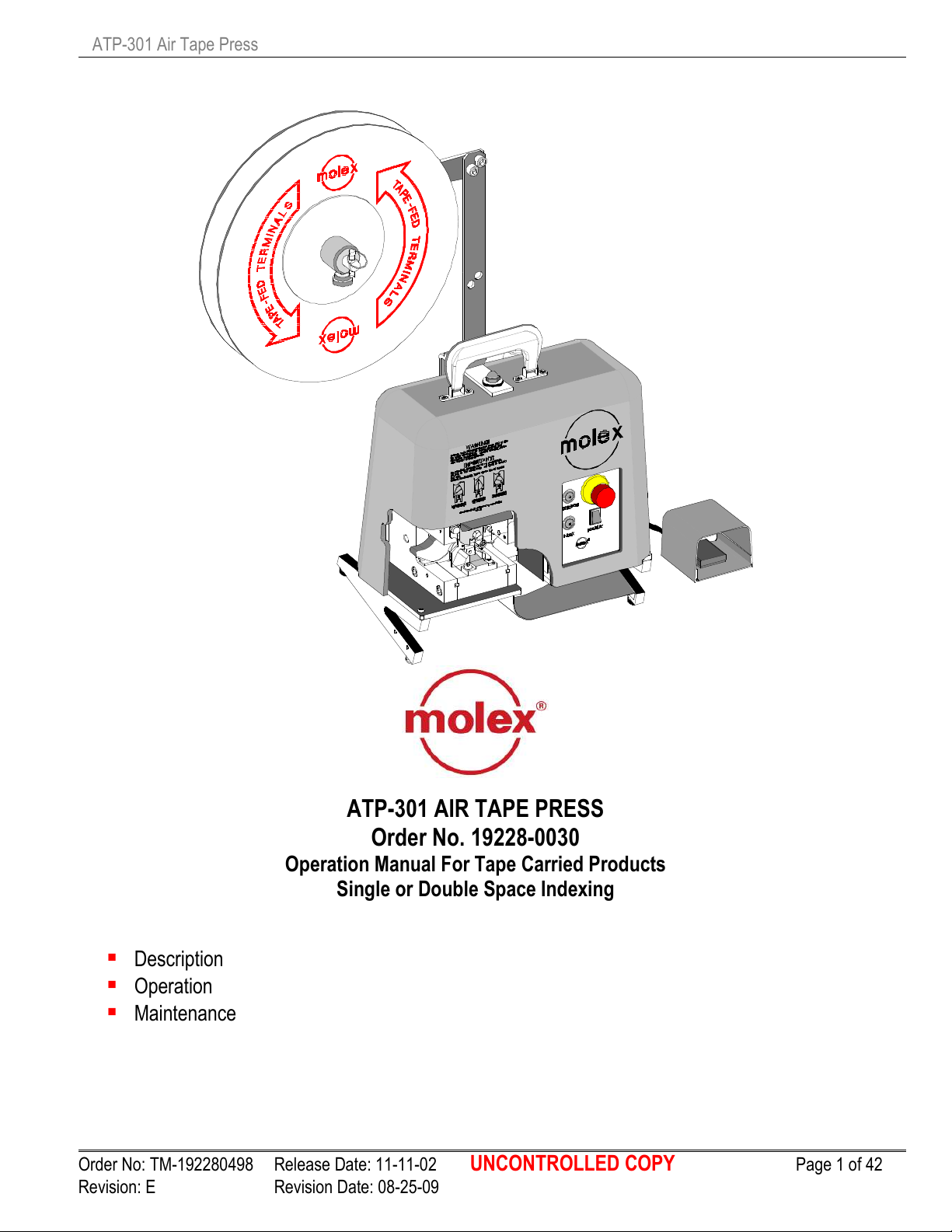
ATP-301 AIR TAPE PRESS
Order No. 19228-0030
Operation Manual For Tape Carried Products
Single or Double Space Indexing
Description
Operation
Maintenance
Order No: TM-192280498 Release Date: 11-11-02 UNCONTROLLED COPY Page 1 of 42
Revision: E Revision Date: 08-25-09
Page 3

ATP-301 Air Tape Press
WARNING
NEVER USE THIS TOOL WITHOUT GUARDS OR SAFETY DEVICES THAT ARE INTENDED TO
PREVENT HANDS FROM REMAINING IN THE CRIMP TOOLING AREA.
NEVER OPERATE, SERVICE, INSTALL OR ADJUST THIS TOOL WITHOUT PROPER INSTRUCTION
AND WITHOUT FIRST READING AND UNDERSTANDING THE INSTRUCTIONS IN THIS
MANUAL AND ALL APPLICABLE AIR POWERED CRIMPING TOOL MANUALS.
NEVER SERVICE THIS MACHINE WHILE IT IS CONNECTED TO ANY ELECTRICAL POWER
SOURCE. DISCONNECT POWER BY UNPLUGGING THE PRESS FROM ITS POWER
SOURCE.
NEVER INSTALL OR REMOVE CRIMP TOOLING WITH THE AIR LINE CONNECTED.
NEVER OPERATE THE PRESS WITH AIR PRESSURE GREATER THAN 110 PSI (AT PRESS
REGULATOR).
CAUTION MOLEX CRIMP SPECIFICATIONS ARE VALID ONLY WHEN USING MOLEX TERMINALS AND
MOLEX APPLICATORS AND TOOLING.
WORK SAFELY AT ALL TIMES
For Service, Contact Your
Local Molex Sales Office
Molex Application Tooling Group
2200 Wellington Court
Lisle, IL 60532
Tel: (630) 969-4550
Fax: (630) 505-0049
Visit our Web site at http://www.molex.com
Order No: TM-192280498 Release Date: 11-11-02 UNCONTROLLED COPY Page 2 of 42
Revision: E Revision Date: 08-25-09
Page 4
ATP-301 Air Tape Press
Table of Contents
SECTION
1 General Description
2 Installation
3 Setup - Operation
4 Maintenance
5 Parts List, Assembly Drawings, Electrical, Pneumatic and Troubleshooting
Order No: TM-192280498 Release Date: 11-11-02 UNCONTROLLED COPY Page 3 of 42
Revision: E Revision Date: 08-25-09
Page 5
ATP-301 Air Tape Press
1.1. Description
1.2. Features
1.3. Technical Specifications
1.4. Delivery Check
1.5. Tools
Section 1
General Description
Order No: TM-192280498 Release Date: 11-11-02 UNCONTROLLED COPY Page 4 of 42
Revision: E Revision Date: 08-25-09
Page 6
ATP-301 Air Tape Press
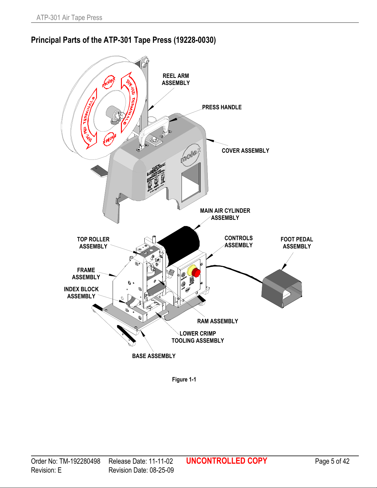
Figure 1
-1
REEL ARM
COVER ASSEMBLY
FOOT PEDAL
MAIN AIR CYLINDER
TOP ROLLER
CONTROLS
INDEX BLOCK
RAM ASSEMBLY
LOWER CRIMP
BASE ASSEMBLY
FRAM
E
PRESS HANDLE
Principal Parts of the ATP-301 Tape Press (19228-0030)
ASSEMBLY
ASSEMBLY
ASSEMBLY
ASSEMBLY
ASSEMBLY
TOOLING ASSEMBLY
ASSEMBLY
ASSEMBLY
Order No: TM-192280498 Release Date: 11-11-02 UNCONTROLLED COPY Page 5 of 42
Revision: E Revision Date: 08-25-09
Page 7
ATP-301 Air Tape Press
General Descrition
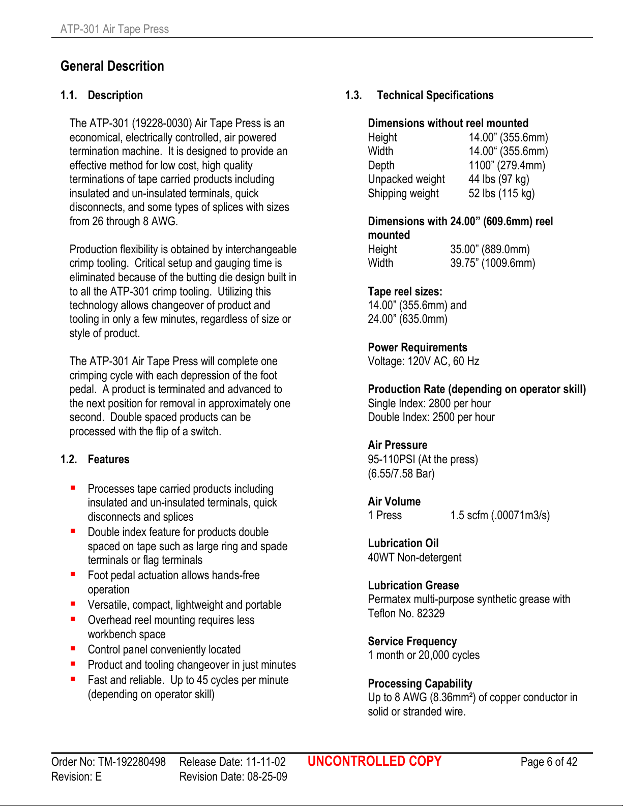
1.1. Description
The ATP-301 (19228-0030) Air Tape Press is an
economical, electrically controlled, air powered
termination machine. It is designed to provide an
effective method for low cost, high quality
terminations of tape carried products including
insulated and un-insulated terminals, quick
disconnects, and some types of splices with sizes
from 26 through 8 AWG.
Production flexibility is obtained by interchangeable
crimp tooling. Critical setup and gauging time is
eliminated because of the butting die design built in
to all the ATP-301 crimp tooling. Utilizing this
technology allows changeover of product and
tooling in only a few minutes, regardless of size or
style of product.
The ATP-301 Air Tape Press will complete one
crimping cycle with each depression of the foot
pedal. A product is terminated and advanced to
the next position for removal in approximately one
second. Double spaced products can be
processed with the flip of a switch.
1.2. Features
Processes tape carried products including
insulated and un-insulated terminals, quick
disconnects and splices
Double index feature for products double
spaced on tape such as large ring and spade
terminals or flag terminals
Foot pedal actuation allows hands-free
operation
Versatile, compact, lightweight and portable
Overhead reel mounting requires less
workbench space
Control panel conveniently located
Product and tooling changeover in just minutes
Fast and reliable. Up to 45 cycles per minute
(depending on operator skill)
1.3. Technical Specifications
Dimensions without reel mounted
Height 14.00” (355.6mm)
Width 14.00“ (355.6mm)
Depth 1100” (279.4mm)
Unpacked weight 44 lbs (97 kg)
Shipping weight 52 lbs (115 kg)
Dimensions with 24.00” (609.6mm) reel
mounted
Height 35.00” (889.0mm)
Width 39.75” (1009.6mm)
Tape reel sizes:
14.00” (355.6mm) and
24.00” (635.0mm)
Power Requirements
Voltage: 120V AC, 60 Hz
Production Rate (depending on operator skill)
Single Index: 2800 per hour
Double Index: 2500 per hour
Air Pressure
95-110PSI (At the press)
(6.55/7.58 Bar)
Air Volume
1 Press 1.5 scfm (.00071m3/s)
Lubrication Oil
40WT Non-detergent
Lubrication Grease
Permatex multi-purpose synthetic grease with
Teflon No. 82329
Service Frequency
1 month or 20,000 cycles
Processing Capability
Up to 8 AWG (8.36mm²) of copper conductor in
solid or stranded wire.
Order No: TM-192280498 Release Date: 11-11-02 UNCONTROLLED COPY Page 6 of 42
Revision: E Revision Date: 08-25-09
Page 8

ATP-301 Air Tape Press
Sound Level
Operator will be exposed to less than 85 DB.
1.4. Delivery Check
19228-0030 Main press assembly
19228-0076 Reel arm assembly
69018-6237 Power cord
63800-8394 Foot pedal assembly
(attached)
TM-192280498 Instruction manual
19228-0497 Fastener kit
(Includes 64016-0068
Stripper / Wire stop assembly)
NOTE: See section 2.1 for unpacking
instructions.
1.5. Tools
The following tools are recommended for setup
and adjustments to the applicator in this press
1. Standard hex wrench set (inch)
2. Adjustable wrench
3. Wire stripper / cutter
4. Scissors
Order No: TM-192280498 Release Date: 11-11-02 UNCONTROLLED COPY Page 7 of 42
Revision: E Revision Date: 08-25-09
Page 9
ATP-301 Air Tape Press
Section 2
Installation
2.1. Unpacking and Positioning the Press
2.2. Reel Arm Assembly Installation
2.3. Air Supply and Electrical Power Connection
2.4. Tape Reel Installation
2.5. Crimp Tooling Installation and Removal
2.6. Insulation Punch Adjustment
2.7. Die Spacer Installation
Order No: TM-192280498 Release Date: 11-11-02 UNCONTROLLED COPY Page 8 of 42
Revision: E Revision Date: 08-25-09
Page 10
ATP-301 Air Tape Press
CROSS MEMBER
3/8”-16 ACORN NUT
3/8”-16 THR
EADED STUD
3/8”-16 SHCS (2)
REEL SHAFT
PRESS HANDLE
AIR COUPLING
AIR LINE W/COUPLING
POWER SUPPLY
POWER CORD
FOOT PEDAL CORD
Figure 2
-2
Read the following instructions before attempting to operate tool.
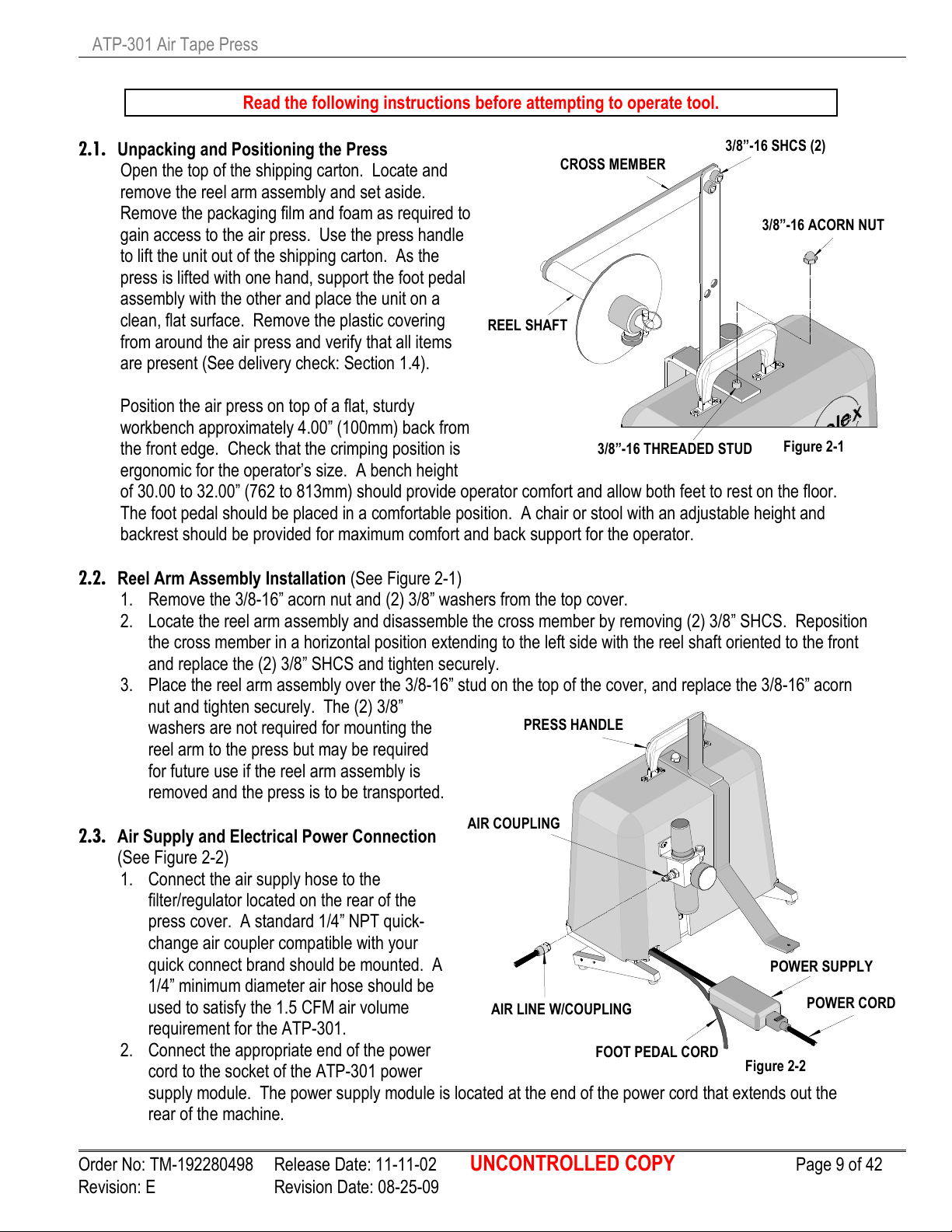
2.1. Unpacking and Positioning the Press
Open the top of the shipping carton. Locate and
remove the reel arm assembly and set aside.
Remove the packaging film and foam as required to
gain access to the air press. Use the press handle
to lift the unit out of the shipping carton. As the
press is lifted with one hand, support the foot pedal
assembly with the other and place the unit on a
clean, flat surface. Remove the plastic covering
from around the air press and verify that all items
are present (See delivery check: Section 1.4).
Position the air press on top of a flat, sturdy
workbench approximately 4.00” (100mm) back from
the front edge. Check that the crimping position is
ergonomic for the operator’s size. A bench height
of 30.00 to 32.00” (762 to 813mm) should provide operator comfort and allow both feet to rest on the floor.
The foot pedal should be placed in a comfortable position. A chair or stool with an adjustable height and
backrest should be provided for maximum comfort and back support for the operator.
2.2. Reel Arm Assembly Installation (See Figure 2-1)
1. Remove the 3/8-16” acorn nut and (2) 3/8” washers from the top cover.
2. Locate the reel arm assembly and disassemble the cross member by removing (2) 3/8” SHCS. Reposition
the cross member in a horizontal position extending to the left side with the reel shaft oriented to the front
and replace the (2) 3/8” SHCS and tighten securely.
3. Place the reel arm assembly over the 3/8-16” stud on the top of the cover, and replace the 3/8-16” acorn
nut and tighten securely. The (2) 3/8”
washers are not required for mounting the
reel arm to the press but may be required
for future use if the reel arm assembly is
removed and the press is to be transported.
2.3. Air Supply and Electrical Power Connection
(See Figure 2-2)
1. Connect the air supply hose to the
filter/regulator located on the rear of the
press cover. A standard 1/4” NPT quick-
change air coupler compatible with your
quick connect brand should be mounted. A
1/4” minimum diameter air hose should be
used to satisfy the 1.5 CFM air volume
requirement for the ATP-301.
2. Connect the appropriate end of the power
cord to the socket of the ATP-301 power
supply module. The power supply module is located at the end of the power cord that extends out the
rear of the machine.
Figure 2-1
Order No: TM-192280498 Release Date: 11-11-02 UNCONTROLLED COPY Page 9 of 42
Revision: E Revision Date: 08-25-09
Page 11
ATP-301 Air Tape Press
REEL SHAFT
THUMB SCREW
DISC
QUICK RELEASE PIN
LOGO FACING
TAPE REEL
Figure 2
-3
CRIMP TOOLING MTG
INSULATION ADJ. CAM
UPPER PUNCH HOLDER
LOWER ANVIL
SAFETY SHEILD
THUMB SCREW
Figure 2
-4
INSULATION ANVIL (I1)
INSULATION PUNCH (I2)
CONDUCTOR PUNCH (E2)
DIE SPACERS (IF REQUIRED)
3. Connect the appropriate end of the power cord to a grounded electrical outlet (120V AC).
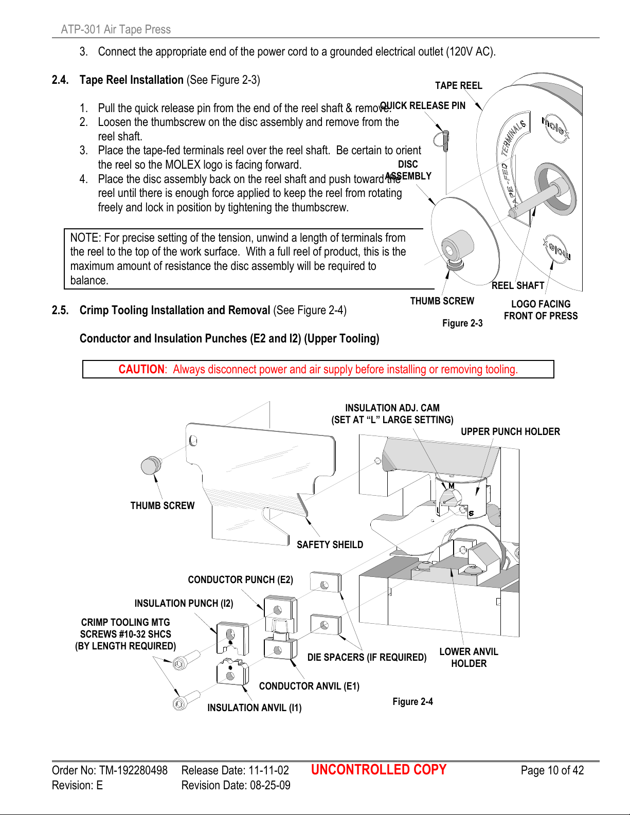
2.4. Tape Reel Installation (See Figure 2-3)
1. Pull the quick release pin from the end of the reel shaft & remove.
2. Loosen the thumbscrew on the disc assembly and remove from the
reel shaft.
3. Place the tape-fed terminals reel over the reel shaft. Be certain to orient
the reel so the MOLEX logo is facing forward.
4. Place the disc assembly back on the reel shaft and push toward the
ASSEMBLY
reel until there is enough force applied to keep the reel from rotating
freely and lock in position by tightening the thumbscrew.
NOTE: For precise setting of the tension, unwind a length of terminals from
the reel to the top of the work surface. With a full reel of product, this is the
maximum amount of resistance the disc assembly will be required to
balance.
2.5. Crimp Tooling Installation and Removal (See Figure 2-4)
Conductor and Insulation Punches (E2 and I2) (Upper Tooling)
CAUTION: Always disconnect power and air supply before installing or removing tooling.
(SET AT “L” LARGE SETTING)
SCREWS #10-32 SHCS
(BY LENGTH REQUIRED)
CONDUCTOR ANVIL (E1)
FRONT OF PRESS
HOLDER
Order No: TM-192280498 Release Date: 11-11-02 UNCONTROLLED COPY Page 10 of 42
Revision: E Revision Date: 08-25-09
Page 12
ATP-301 Air Tape Press
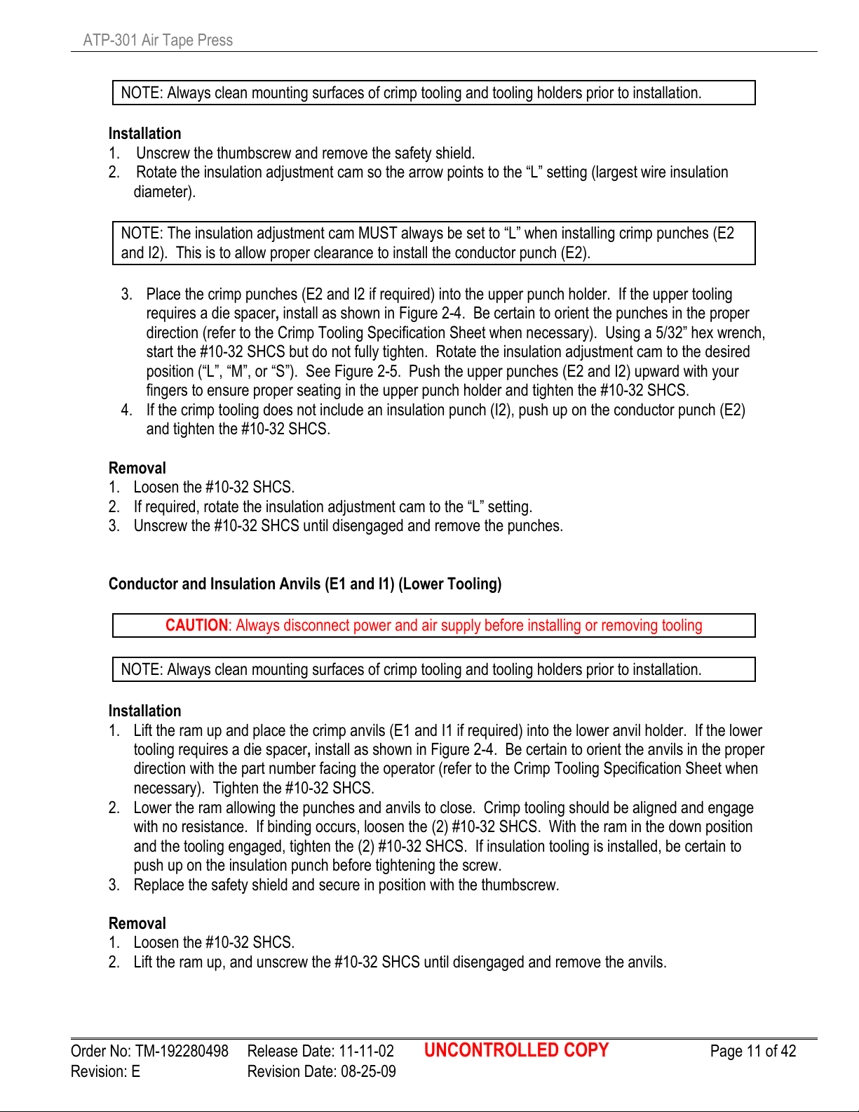
NOTE: Always clean mounting surfaces of crimp tooling and tooling holders prior to installation.
Installation
1. Unscrew the thumbscrew and remove the safety shield.
2. Rotate the insulation adjustment cam so the arrow points to the “L” setting (largest wire insulation
diameter).
NOTE: The insulation adjustment cam MUST always be set to “L” when installing crimp punches (E2
and I2). This is to allow proper clearance to install the conductor punch (E2).
3. Place the crimp punches (E2 and I2 if required) into the upper punch holder. If the upper tooling
requires a die spacer, install as shown in Figure 2-4. Be certain to orient the punches in the proper
direction (refer to the Crimp Tooling Specification Sheet when necessary). Using a 5/32” hex wrench,
start the #10-32 SHCS but do not fully tighten. Rotate the insulation adjustment cam to the desired
position (“L”, “M”, or “S”). See Figure 2-5. Push the upper punches (E2 and I2) upward with your
fingers to ensure proper seating in the upper punch holder and tighten the #10-32 SHCS.
4. If the crimp tooling does not include an insulation punch (I2), push up on the conductor punch (E2)
and tighten the #10-32 SHCS.
Removal
1. Loosen the #10-32 SHCS.
2. If required, rotate the insulation adjustment cam to the “L” setting.
3. Unscrew the #10-32 SHCS until disengaged and remove the punches.
Conductor and Insulation Anvils (E1 and I1) (Lower Tooling)
CAUTION: Always disconnect power and air supply before installing or removing tooling
NOTE: Always clean mounting surfaces of crimp tooling and tooling holders prior to installation.
Installation
1. Lift the ram up and place the crimp anvils (E1 and I1 if required) into the lower anvil holder. If the lower
tooling requires a die spacer, install as shown in Figure 2-4. Be certain to orient the anvils in the proper
direction with the part number facing the operator (refer to the Crimp Tooling Specification Sheet when
necessary). Tighten the #10-32 SHCS.
2. Lower the ram allowing the punches and anvils to close. Crimp tooling should be aligned and engage
with no resistance. If binding occurs, loosen the (2) #10-32 SHCS. With the ram in the down position
and the tooling engaged, tighten the (2) #10-32 SHCS. If insulation tooling is installed, be certain to
push up on the insulation punch before tightening the screw.
3. Replace the safety shield and secure in position with the thumbscrew.
Removal
1. Loosen the #10-32 SHCS.
2. Lift the ram up, and unscrew the #10-32 SHCS until disengaged and remove the anvils.
Order No: TM-192280498 Release Date: 11-11-02 UNCONTROLLED COPY Page 11 of 42
Revision: E Revision Date: 08-25-09
Page 13
ATP-301 Air Tape Press
RAM
“S” SETTING FOR
INSULATION CRIMP PUNCH IS IN
CRIMP PUNCH
UPPER PUNCH
“L” SETTING FOR
“M” SETTING FOR MEDIUM
INSULATION CRIMP PUNCH IS IN
INSULATION
Figure
2-5
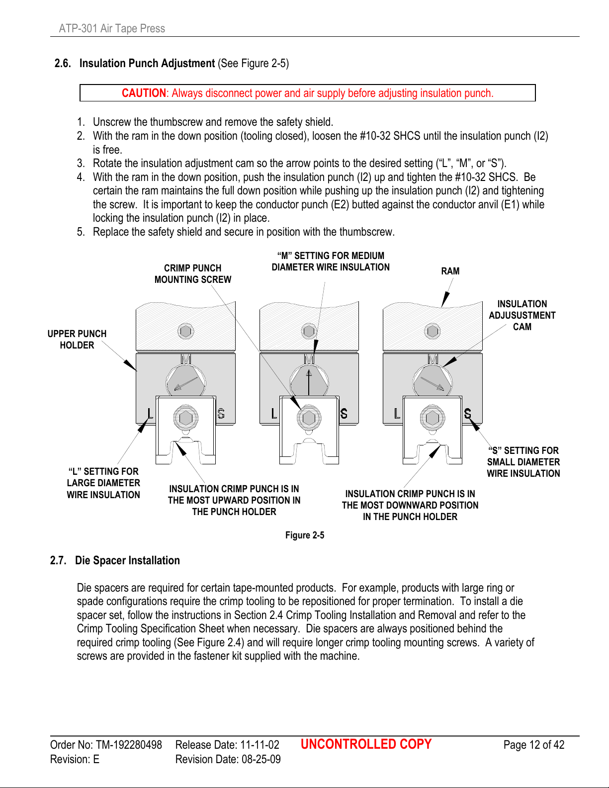
2.6. Insulation Punch Adjustment (See Figure 2-5)
CAUTION: Always disconnect power and air supply before adjusting insulation punch.
1. Unscrew the thumbscrew and remove the safety shield.
2. With the ram in the down position (tooling closed), loosen the #10-32 SHCS until the insulation punch (I2)
is free.
3. Rotate the insulation adjustment cam so the arrow points to the desired setting (“L”, “M”, or “S”).
4. With the ram in the down position, push the insulation punch (I2) up and tighten the #10-32 SHCS. Be
certain the ram maintains the full down position while pushing up the insulation punch (I2) and tightening
the screw. It is important to keep the conductor punch (E2) butted against the conductor anvil (E1) while
locking the insulation punch (I2) in place.
5. Replace the safety shield and secure in position with the thumbscrew.
MOUNTING SCREW
DIAMETER WIRE INSULATION
ADJUSUSTMENT
HOLDER
LARGE DIAMETER
WIRE INSULATION
THE MOST UPWARD POSITION IN
THE PUNCH HOLDER
THE MOST DOWNWARD POSITION
IN THE PUNCH HOLDER
SMALL DIAMETER
WIRE INSULATION
2.7. Die Spacer Installation
Die spacers are required for certain tape-mounted products. For example, products with large ring or
spade configurations require the crimp tooling to be repositioned for proper termination. To install a die
spacer set, follow the instructions in Section 2.4 Crimp Tooling Installation and Removal and refer to the
Crimp Tooling Specification Sheet when necessary. Die spacers are always positioned behind the
required crimp tooling (See Figure 2.4) and will require longer crimp tooling mounting screws. A variety of
screws are provided in the fastener kit supplied with the machine.
CAM
Order No: TM-192280498 Release Date: 11-11-02 UNCONTROLLED COPY Page 12 of 42
Revision: E Revision Date: 08-25-09
Page 14
ATP-301 Air Tape Press
3.1. Control Panel Operation
3.2. Loading Taped Product
3.3. Removing Taped Product
3.4. Wire Stop Installation
3.5. Stripper Installation
Section 3
Setup-Operation
Order No: TM-192280498 Release Date: 11-11-02 UNCONTROLLED COPY Page 13 of 42
Revision: E Revision Date: 08-25-09
Page 15

ATP-301 Air Tape Press
POWER
MANUAL
E-STOP BUTTON
Figure 3
-1
DOUBLE
3.1. Control Panel Operation (See Figure 3-1)
1. Pressing POWER ON (momentary) push button
permits power to the machine unless one or both of
the following conditions exist.
a) The power cord is not properly plugged in a power
ON
BUTTON
source.
b) The E-STOP push button is depressed (in the off
position).
This green push button will illuminate when power is
INDEX
BUTTON
on.
2. Pressing the E-STOP push button will power down the
machine. This is a locking push button. To reset the
(INDEX
SWITCH)
E-STOP, rotate the push button clockwise until it
resets. The switch will pop out when reset. The
POWER ON push button will not supply power to the
machine until the E-STOP is reset.
3. The INDEX (momentary) push button is used to index the tape product without terminating the terminals.
This push button operates in two stages described below.
a) Pressing this push button the first time will cause the ram to rise to the full up position and index the
tape. This red push button will flash on and off when the machine is in this condition.
b) Pressing this push button a second time will allow the ram to lower down but will not actuate the main
ram cylinder for termination. The ram will fall down and capture the terminal (if present in the
termination position). The push button will stop flashing at this time to indicate that it is no longer
active.
NOTE: When the red INDEX push button is depressed and no motion is performed, the red light will flash
on and off. One or both of the following conditions may exist.
a) The E-STOP push button is depressed (in the off position). Push INDEX one time to stop the flashing
condition. Rotate the E-STOP clockwise to reset and press the POWER ON push button to restore
power to the machine.
b) The air supply is disconnected. Press INDEX one time to stop the flashing condition. Reconnect the
airline. Push INDEX to initiate the index cycle.
CAUTION: It is recommended to always deactivate the index cycle by pressing INDEX one time to stop
the flashing condition before POWER ON or RECONNECTING the air supply. If the light is flashing, the
machine will perform the index immediately upon restoration of power or air supply.
4. The DOUBLE INDEX (rocker) switch changes the machine from single index mode to double index
mode. When this switch is in the off position (the “o” symbol on the lower half of switch depressed), the
machine will single index. When this switch is on (the “l” symbol on the upper half of switch depressed),
the machine will perform double indexing.
NOTE: The following two items are not on the control panel.
5. The WORKLAMPS will remain illuminated at all times as long as there is power to the machine. There
is no on/off switch for the work lamps.
Order No: TM-192280498 Release Date: 11-11-02 UNCONTROLLED COPY Page 14 of 42
Revision: E Revision Date: 08-25-09
Page 16

ATP-301 Air Tape Press
CUT TAPE ON A
Figure3
-2
Figure 3
-3
TAPE INDEX WHEEL
UPPER TAPE GUIDE
LOWER TAPE GUIDE
CARRIER TAPE
LOWER ANVIL HOLDER
SAFETY SHIELD
UPPER PU
NCH HOLDER
TERMINAL
6. The FOOT PEDAL (SWITCH) should be placed on the floor and positioned for operator comfort.
Pressing the foot pedal and releasing will initiate one press cycle.
3.2. Loading Taped Product (See Figure 3-3)
DIAGONAL
1. Prepare the tape for loading. Use scissors to cut the tape
on a diagonal. The diagonal cut must pass between the
slots in the tape. See Figure 3-2.
2. Slide the tape between the upper and lower tape guides
with the rear edge of the tape against the rail on the lower
guide. Push the tape to the right into the mechanism until
the slot in the tape engages to first tooth on the index
wheel. Listen for a click sound when the slot snaps over
the tooth in the wheel.
NOTE: If the wire stop assembly is installed, check position of tape after each index to ensure the tape has
passed under the wire stop. It may be necessary to lift the wire stop over the tape.
Depending on the condition of the tape, the above step may have to be repeated until successful.
3. Press the Index push button on the control panel twice to index the tape (See Section 3.1, Item 3 for
more details on the Index push button). Repeat this step as necessary until a terminal is in the
termination position centered over the lower anvil or anvils.
NOTE: It is recommended the operator always observe the tape as it passes through the exit guides
to the right of the crimp tooling. Adjustment of the tape may be required to maintain a smooth flow of
the used tape through the upper and lower exit guides.
Order No: TM-192280498 Release Date: 11-11-02 UNCONTROLLED COPY Page 15 of 42
Revision: E Revision Date: 08-25-09
Page 17

ATP-301 Air Tape Press
Figure 3
-4
THUMBSCREW
LOCATE AND PUSH LIP
#10-32 X 3/4” SHCS
SIDE PLATE
WIRE STOP BLADE
STRIPPER /WIRE
STOP
64016
-
0068 STRIPPER/ WIRE STOP CONFIGURATIONS
WIRE STOP ASSEMBLY
STRIPPER ASSEMBLY
3.3 Removing Taped Product
1. When 5 wires remain to be terminated, cut the tape off with 4 terminals to the left of the crimp tooling.
2. When terminations are complete, cycle or index the machine as required to allow the tape to exit the
feed mechanism. The foot switch or the index push button can be used to run the tape out of the
machine.
ASSEMBLY (AS SHIPPED)
(STRIPPER REMOVED)
(WIRE STOP REMOVED)
3.4 Wire Stop Installation
Note: The Wire Stop Assembly is not installed at the factory. It is supplied with the machine and can be
installed at anytime. It is recommended for use with terminals that do not have a wire stop feature such as
un-insulated rings and spades.
Prior to installing the wire stop into the press, remove the stripper from the sub-assembly. See stripper/wire
stop configurations. This is done by removing the #10-32 Low Head SHCS from the end of the support that
mounts the stripper.
CAUTION: Always disconnect power and air supply before installing or removing wire stop.
FOR SAFETY SHIELD
OF MOUNTING BLOCK
UNDER THE SIDE PLATE
(SHOWN WITH TOOLING REMOVED)
Order No: TM-192280498 Release Date: 11-11-02 UNCONTROLLED COPY Page 16 of 42
Revision: E Revision Date: 08-25-09
Page 18

ATP-301 Air Tape Press
GAP
TERMINAL
TAPE
WIRE STOP
SUPPORT
TOP VIEW (Termi
nation area with wire stop)
#10-32 X 3/4”LG. SHCS
C
ONDUCTOR
.250 DIA. X .125 LG.
1. Unscrew the thumbscrew and remove the safety shield.
NOTE: Although not necessary, it is recommended that all crimp tooling and taped products be removed
before mounting the wire stop assembly.
2. Position the wire stop assembly on the inside wall of the right side plate. Be certain the lip of the support
block locates under the edge of the side plate and secure with the #10-32 x 3/4” SHCS into the far #10-32
tapped hole. See Figure 3-4.
NOTE: Crimp tooling must be installed for the following step.
3. To properly position the wire stop, loosen the
#10-32 SHCS. While pushing up on the
mounting block, slide the assembly in or out
BLADE
SOC SHOULDER SCREW
to achieve the required gap between the rear
of the terminal conductor barrel and the front
face of the wire stop blade (See Figure 3-5)
(ADJUST AS
REQUIRED)
and lock in place by tightening the #10-32
SHCS.
4. Replace the safety shield and secure in
position with the thumbscrew.
NOTE: Taped product must be loaded for the
following step.
ANVIL (E1)
5. Make a test sample to evaluate the position
of the wire stop. If the wire brush on the far
side of the terminal is too long or too short,
CONDUCTOR
BARREL
adjust the gap between the conductor barrel
and wire stop blade per step 3 above.
Figure 3-5
3.5 Stripper Installation
Note: The Stripper Assembly is not installed at the factory. It is supplied with the machine and can be
installed at anytime. It is recommended for use with terminals that stick in the conductor punch after
termination.
Prior to installing the wire stripper into the press, remove the wire stop from the sub-assembly. See
stripper / wire stop configurations. This is done by removing the 1/4” diameter x 1/8” long Shoulder Screw
from the end of the support bar that mounts the wire stop blade.
CAUTION: Always disconnect power and air supply before installing or removing wire stripper.
1. Unscrew the thumbscrew and remove the safety shield.
NOTE: Although not necessary, it is recommended that all crimp tooling and taped products be removed
before mounting the stripper assembly.
WIRE STOP
Order No: TM-192280498 Release Date: 11-11-02 UNCONTROLLED COPY Page 17 of 42
Revision: E Revision Date: 08-25-09
Page 19

ATP-301 Air Tape Press
STRIPPER GAP
ANVIL (E1/I1)
STRIPPER BAR
#10-32 SHCS FOR
Figure 3
-6
LO
CATE AND PUSH LIP
TERMINAL TO BE CRIMPED
#10-32 X 1/2” LG.
#10-32 X 3/4” LG.
2. Position the stripper assembly on the inside wall of the right side plate. Be certain the lip of the support
block locates under the edge of the side plate and install the #10-32 x 3/4” SHCS into the far #10-32
tapped hole. Slide the block all the way forward (toward you) and tighten the #10 SHCS. See Figure 3-
6.
PUNCH (E2/I2)
LOW HEAD SHCS
(STRIPPER HEIGHT ADJUST)
SEE NOTE 5
OF MOUNTING BLOCK
UNDER THE SIDE PLATE
(STRIPPER IN/OUT ADJUST)
3. Adjust the height of stripper bar by loosening the #10-32 x 1/2“ Low Head SHCS and position the
stripper bar up and down in the center of the mounting slot and tighten the screw.
NOTE: Crimp tooling must be installed for the following step.
4. To properly position the support block depth, loosen the #10-32 x 3/ 4” SHCS and slide the entire
assembly in until the stripper pad clears to #10-32 SHCS that mounts the conductor (E2) or insulation
(I2) punch and tighten the #10-32 SHCS. See Figure 3-6.
NOTE: Taped product must be loaded for the following step.
5. Adjust the stripper gap by positioning the stripper bar height. Loosen the #10-32 x 1/2” Low Head SHCS
on the end of the support block and slide the stripper bar down so it is positioned just above the terminal
that is to be crimped, and tighten the #10 Low Head SHCS. See Figure 3-6. To verify the stripper gap,
push the index button twice to advance the terminal. Repeat this several times. If the terminal does not
position properly between the punch and anvil, increase the stripper gap as required until the terminal
positions properly.
Order No: TM-192280498 Release Date: 11-11-02 UNCONTROLLED COPY Page 18 of 42
Revision: E Revision Date: 08-25-09
Page 20

ATP-301 Air Tape Press
Section 4
Maintenance
4.1 Cleaning
4.2 Compressed Air System Maintenance
4.3 Lubrication
4.4 Spare Parts
4.5 Perishable Parts
Order No: TM-192280498 Release Date: 11-11-02 UNCONTROLLED COPY Page 19 of 42
Revision: E Revision Date: 08-25-09
Page 21

ATP-301 Air Tape Press
4.1. Cleaning
WARNING: Disconnect electrical power and
air supply before all maintenance.
For efficient operation, the ATP-301 Tape Press
should be cleaned daily. Use a soft bristle brush to
remove debris from critical areas such as the crimp
tooling and tape feed wheel assembly. For best
results, remove the safety shield, taped product,
and crimp tooling from the press. Using your
thumb, lift open the upper tape guide and brush out
all debris between the upper and lower tape feed
guides, around the tape feed wheel, and to the right
where the tape exits the machine. Brush and then
use a clean cloth to wipe off the upper and lower
tooling mounting areas. Before reinstalling tooling,
wipe all sides of the punches and anvils with a
clean cloth.
Use window cleaner and cloth to clean the safety
shield. Never use solvents. If the shield is
severely scuffed or scratched, replacement may be
necessary. See Section 5 for part numbers.
CAUTION: Never use compressed air to clean the
machine.
4.2. Compressed Air System Maintenance
WARNING: Disconnect electrical power and air
supply before all maintenance.
Due to the nature of the system, air compressors
commonly create condensation and moisture in the
system. This will cause problems in any pneumatic
piece of equipment. The moisture will cause
premature corrosion inside the valves and device.
As the tool operates, commonly there is an exhaust
port that will spray the moisture out and cause the
mechanical aspect of the tool to corrode. This tool
is designed for a clean, dry air system. To
maximize the life span of your tool you should
maintain a low moisture system. This may include
a weekly spot check of the moisture in your lines.
This can be checked easily. Connect an air nozzle
to a low point in the hard piping or near the press.
Blowing air onto a piece of paper for a period of
time, you will see if any moisture is being
circulated.
All air compressors have a dump valve or plug on
the underside of the tank. With the compressor
off and no pressure in the system . . . you can
open this and drain any built up moisture. There
can also be moisture collected in the drop down
pipes from overhead. There should be an extra
length of pipe with a valve to drain. Water can
collect at these points, and not be blown through.
4.3. Lubrication
For trouble free operation, regular maintenance is
mandatory. The following maintenance procedures
will help ensure top quality machine performance.
Depending on machine usage, the time between
maintenance can vary. For machines with high
daily cycle counts, over 1,000 cycles per day,
maintenance is required more often than machines
used for lower volumes, under 1,000 cycles per
day. It is recommended to perform the following
maintenance at least every 20,000 cycles. This
could be once a month for low volume users or
every two to three days for high volume production.
The following formula and examples can be used to
determine maintenance frequency:
C x H = D then 20,000 ÷ D = #
Where: C = cycles per hour
H = hours per day
D = cycles per day
20,000 = maintenance frequency
# = Number of days between
maintenance
Example for a low volume user: 220 cycles
per hour for 4 hours per day
220 x 4 = 880 and then 20,000 ÷ 880 = 22.72
or maintenance every 23 days.
Example for a high volume user: 360 cycles
per hour for 8 hours per day
360 x 8 = 2,880 and then 20,000 ÷ 2,880 =
6.94 or maintenance every 7 days.
Order No: TM-192280498 Release Date: 11-11-02 UNCONTROLLED COPY Page 20 of 42
Revision: E Revision Date: 08-25-09
Page 22

ATP-301 Air Tape Press
Figure 4
-1
GREASE
OIL
GREASE
FRONT
GREASE
BACK
GREASE
WARNING: Disconnect electrical power and air supply before all maintenance.
1. Remove the 3/8-16” acorn nut from the top of the press.
2. Remove and set aside the reel arm assembly.
3. Remove and set aside the cover assembly. Use caution when lifting the cover. The lower edge of the
opening for the control panel can interfere with push buttons and damage the controls.
4. Lubricate all points shown in Figures 4-1 with the specified oil and grease (or equivalent).
Lubricate with 40WT non-detergent oil and grease with Permatex multi-purpose synthetic grease with
Teflon No. 82329.
WARNING: Never use solvents or penetrants for any lubrication on the machine.
5. Replace the cover and reel arm assemblies, and secure with the 3/8-16” acorn nut.
An example of a maintenance chart is shown below. Copy and use this chart to track the maintenance of
your ATP-301 or use this as a template to create you own schedule or use your company’s standard chart if
applicable.
Order No: TM-192280498 Release Date: 11-11-02 UNCONTROLLED COPY Page 21 of 42
Revision: E Revision Date: 08-25-09
Page 23

ATP-301 Air Tape Press
Preventive Maintenance Chart
Daily: Clean (See Section 4.1).
As Required: Lubrication (See Section 4.3).
CHECK SHEET MONTH YEAR _________
Week Daily Clean
1
2
3
4
(As Required)
Lubricate
Schedule should be adjusted up or down depending on usage. Molex recommends that a log of preventive
maintenance be kept with the press.
4.4 Spare Parts
Customers are responsible for maintaining the ATP-301 Air Tape Press. Spare parts are available.
Moving and functioning parts can be damaged or wear out over time and will require replacement.
Molex recommends that the customer keep some or all of them in stock to reduce production down time.
These parts are identified in the Parts List. See Section 5.
4.5 Perishable Parts
Customers are responsible for maintaining the ATP-301 Air Tape Press. Perishable parts are those
parts that come in contact with the product and may wear out over time. Molex recommends that all
customers keep at least one set of the perishable tool kit in stock at all times. This will reduce the
amount of production down time. For the proper perishable tool kit information, refer to the Crimp
Tooling Specification Sheet supplied with the tool kit.
MON TUE WED THU FRI SAT SUN
Days of the Week
Order No: TM-192280498 Release Date: 11-11-02 UNCONTROLLED COPY Page 22 of 42
Revision: E Revision Date: 08-25-09
Page 24

ATP-301 Air Tape Press
5.1. Parts Lists and Assembly Drawings
5.2. Electrical Schematic
5.3. Pneumatic Diagram
5.4. Troubleshooting
Section 5
Order No: TM-192280498 Release Date: 11-11-02 UNCONTROLLED COPY Page 23 of 42
Revision: E Revision Date: 08-25-09
Page 25

ATP-301 Air Tape Press
5.1. Parts List and Assembly Drawings
19228-0030 Air Tape Press Figure 1-1
Figure Description Qty
Figure 5-1 Ram/Index Cylinder Assembly 1
Figure 5-2 Main Air/Top Roller Assembly 1
Figure 5-3 Index Block Assembly 1
Figure 5-4 Lower Tooling Assembly 1
Figure 5-5 Base Assembly 1
Figure 5-6 Cover Assembly 1
Figure 5-7 Reel Arm Assembly 1
Figure 5-8 Frame Assembly 1
Figure 5-9 Controls Assembly 1
Ram / Index Cylinder Parts List (See Figure 5-1)
Ram/Index Cylinder Assembly Figure 5-1
Item Order No. Engineering No. Description Qty
1 11-31-6809 AM60018-46 Male Connector #10-32 THD-5/32” Tube 1**
2 11-32-1111 AM60001-150 Male Connector #10-32 THD-1/4” Tube 1**
3 19228-0068 23195-01 Index Cylinder Assembly 1
4 19228-0108 23155-02 Ram Roller - Lower 1
5 19228-0109 23155-03 Ram Lift Pin 1
6 19228-0116 23155-27 Light Deflector 1
7 19228-0138 23156-31 Index Lever 1
8 19228-0147 23157-07 Cam - Insulation Crimp 1
9 19228-0199 23155-01 Ram 1
10 19228-0201 23157-05 Upper Punch Holder 1
11 19228-0204 23154-07 Block - Ram Guide 1
12 19228-0240 23157-06 Back Plate-Upper Punch Holder 1
13 19228-0406 23155-11 Ram Lock Screw 1
14 62500-1172 62500-1172 Miniature Lamp 2
15 63700-3795 63700-3795 Precision Pivot Pin 1
16 63700-3796 63700-3796 Bushing-Ram Guide 1
17 64000-0008 64000-0008 Key 2
18 64000-0097 64000-0097 Work Light Assembly 1
19 N/A N/A E-Ring. (5/32” External) 1**
20 N/A N/A 3/8-16 Jam Nut 1**
21 N/A N/A #6-32 by 1/4” Long BHCS 4**
22 N/A N/A #8-32 by 1/2” Long SHCS 2**
23 N/A N/A #10-32 by 1-1/4” Long SHCS 2**
24 N/A N/A #8-32 by 3/16” Long SSS (Cup Pt.) 1**
25 N/A N/A 1/4-20 by 3/8” Long SSS (Cup Pt. with Nylok) 1**
26 N/A N/A Retaining Ring (1/8” External) 1**
27 N/A N/A Retaining Ring (3/8” External) 1**
The components indicated with **are available from an Industrial supply company such as MSC (1-800-645-7270).
Order No: TM-192280498 Release Date: 11-11-02 UNCONTROLLED COPY Page 24 of 42
Revision: E Revision Date: 08-25-09
Page 26

ATP-301 Air Tape Press
RAM/INDEX CYLINDER ASSEMBLY
(2)
6
23
13
4
14
7
12
17
20
10
25
(2)
16
8
1
24
2
18
(2)
15
3
26
(2)
(2)
21
27
9
22
19
(2)
21
5
11
(2)
Ram / Index Cylinder Assembly
Figure 5-1
Order No: TM-192280498 Release Date: 11-11-02 UNCONTROLLED COPY Page 25 of 42
Revision: E Revision Date: 08-25-09
Page 27

ATP-301 Air Tape Press
(2)
MAIN AIR CYLINDER/ TOP
ROLLER ASSEMBLY
1
7
11
15
9
16
18
19
8
12
5
17
4
13
14
20
18
10
3
6
(3)
(2)
(2)
2
(2)
Main Air Cylinder / Top Roller Parts List (See Figure 5-2)
Main Air Cylinder / Top Roller Assembly Figure 5-2
Item Order No. Engineering No. Description Qty
1 11-31-1897 R8432-23 Male Elbow Fitting (1/8” NPT- 1/4” Tube) 1**
2 11-31-6809 AM60018-46 Male Connector (#10-32 THD-5/32” Tube) 1**
3 11-32-1061 AM60001-124 Male Elbow Fitting (1/4” NPT- 3/8” Tube) 1**
4 19228-0106 23154-10 Top Roller Pin 1
5 19228-0110 23155-05 Top Roller 1
6 19228-0112 23155-15 Power Cam Pin 1
7 19228-0113 23155-16 Power Cam 1
8 19228-0172 23194-01 Ram Lift Cylinder 1
9 19228-0186 23154-04 Top Roller Block 1
10 19228-0194 23192-02 Main Air Cylinder 1
11 19228-0207 23561-26D Right Side Plate REF
12 64000-0007 64000-0007 Key 2
13 N/A N/A #4-40 by 1/4” Long SHCS 1**
14 N/A N/A #6 Washer (Common) 1**
15 N/A N/A 1/4-20 by 3/4” Long SHCS 3**
16 N/A N/A #10-32 by 1-1/4” Long SHCS 2**
17 N/A N/A #8-32 by 3/16” Long SSS (Cup Pt.) 1**
18 N/A N/A #10-32 by 1/4” Long SSS (Cup Pt.) 2**
19 N/A N/A #10 Lock Washer 2**
20 N/A N/A Retaining Ring (1/4” External) 2**
The components indicated with **are available from an Industrial supply company such as MSC (1-800-645-7270).
Main Air Cylinder / Top Roller Assembly
Figure 5-2
Order No: TM-192280498 Release Date: 11-11-02 UNCONTROLLED COPY Page 26 of 42
Revision: E Revision Date: 08-25-09
Page 28

ATP-301 Air Tape Press
Index Block Parts List (See Figure 5-3)
Item Order No. Engineering No. Description Qty
1
19228-0124 23156-04 Tape Index Wheel 1
2
19228-0125 23156-07 Tape Driver Disk 1
3
19228-0127 23156-03 Thrust Bearing 1
4
19228-0128 23156-10 Ratchet Wheel 1
5
19228-0132 23156-18 Index Arm Guide 1
6
19228-0135 23156-25 Plain Bearing 1
7
19228-0136 23156-26 Housing-Ball Detent 1
8
19228-0137 23156-27 Ball Detent 1
9
19228-0141 23156-46 Spring Hold Down 1
10 19228-0142 23156-47 Spring Hold Down Post 1
11 19228-0187 23154-09 Ratchet Index Block 1
12 19228-0188 23156-44 Tape Hold Down 1
13 19228-0209 23156-30 Index Cam Deflector 1
14 19228-0400 23156-06 Tape Driver Shaft 1
15 19411-0146 26220-704 Thrust Washer 2
16
17
18
19
20
21
22
23
24
25
26
The components indicated with **are available from an Industrial supply company such as MSC (1-800-645-7270).
N/A N/A #8 Lock Washer 1**
N/A N/A #8-32 by 1/2” Long SHCS 1**
N/A N/A #8-32 by 3/4” Long BHCS 1**
N/A N/A #8-32 by 3/4” Long SHCS 2**
N/A N/A #10-32 by 1.0” Long SHCS 1**
N/A N/A 3/32” by 3/8”Long Dowel Pin 2**
N/A N/A 3/32” by 1/2”Long Dowel Pin 2**
N/A N/A 5/32” Diameter Steel Ball 1**
N/A N/A Compression Spring (.18” O.D. by .032” W. by .88” Lg.) 1**
N/A N/A Compression Spring (.24” O.D. by .032” W. by 1.0” Lg.)) 1**
N/A N/A Shim Washer (.50” I.D. by 1.13” O.D. by .010” Lg.) 1**
Index Block Assembly Figure 5-3
Order No: TM-192280498 Release Date: 11-11-02 UNCONTROLLED COPY Page 27 of 42
Revision: E Revision Date: 08-25-09
Page 29

ATP-301 Air Tape Press
(2)
(2)
16
4
21
3
15
26
24
17
8
(2) 19
5
13
12
11
6
10
9
25
INDEX BLOCK ASSEMBLY
(2)
23
7
14
1
2
22
18
20
Index Block Assembly
Figure 5-3
Order No: TM-192280498 Release Date: 11-11-02 UNCONTROLLED COPY Page 28 of 42
Revision: E Revision Date: 08-25-09
Page 30

ATP-301 Air Tape Press
(2) 8
L
OWER TOOLING ASSEMBLY
1
4
3
6
2
7
5
(2)
Lower Tooling Parts List (See Figure 5-4)
Lower Tooling Assembly Figure 5-4
Item Order No. Engineering No. Description Qty
1 19228-0145 23157-02 Lower Anvil Holder 1
2 19228-0146 23157-03 Back Plate- Lower Anvil Holder 1
3 19228-0189 23156-45 Auto Tape Start 1
4 19228-0218 23154-08 Front Base Block 1
5 64000-0008 64000-0008 Key 2
6 N/A N/A #8-32 by 3/8” Long FHCS 1**
7 N/A N/A #10-32 by 1/2” Long SHCS 1**
8 N/A N/A 1/4-20 by 3/4” Long BHCS 2**
The components indicated with **are available from an Industrial supply company such as MSC (1-800-645-7270).
Lower Tooling Assembly
Figure 5-4
Order No: TM-192280498 Release Date: 11-11-02 UNCONTROLLED COPY Page 29 of 42
Revision: E Revision Date: 08-25-09
Page 31

ATP-301 Air Tape Press
(4)
BASE ASSEMBLY
1
7
2
5
9
8
4
6
7
7
(2)
(2)
(4)
(2)
3
Base Parts List (See Figure 5-5)
Item Order No. Engineering No. Description Qty
1 19228-0102 23151-07 Rubber Bumper with Stud 4
2 19228-0103 23151-10 Upper Tape Guide 1
3 19228-0104 23151-11 Lower Tape Guide 1
4 19228-0107 23154-28 Mounting Bracket 1
5 19228-0206 23154-23 Base Plate 1
6 19228-0215 23151-09 Tilt Leg 2
7 N/A N/A #10-32 by 1/4” Long BHCS 4**
8 N/A N/A #10-32 by 1/2” Long BHCS 2**
9 N/A N/A #10-32 by 3/4” Long BHCS 4**
The components indicated with **are available from an Industrial supply company such as MSC (1-800-645-7270).
Base Assembly
Base Assembly Figure 5-5
Figure 5-5
Order No: TM-192280498 Release Date: 11-11-02 UNCONTROLLED COPY Page 30 of 42
Revision: E Revision Date: 08-25-09
Page 32

ATP-301 Air Tape Press
(2)
COVER ASSEMBLY
3
1
8
5
7
4
6
(4)
2
9
10
(2)
11
Cover Parts List (See Figure 5-6)
Item Order No. Engineering No. Description Qty
1 11-31-8944 AM60506P109 Male Elbow (1/4”NPT-1/4” Tube) 1**
2 19228-0117 23155-30 Handle Bracket 1
3 19228-5001 19228-5001 Nut Plate – Air Regulator 1
4 19818-5010 19818-5010 Cover 1
5 62500-0189 62500-0189 Filter Regulator 1
6 63700-3274 63700-3274 Handle 1
7 N/A N/A #6-32 by 1/2” Long FHCS 4**
8 N/A N/A #10-32 by 3/4” Long BHCS 2**
9 N/A N/A 3/8-16 Acorn Nut 1**
10 N/A N/A 3/8” Washer (common) 2**
11 N/A N/A Air Coupler 1/4 NPT (to Suit by Customer) REF ONLY**
The components indicated with **are available from an Industrial supply company such as MSC (1-800-645-7270).
Cover Assembly
Figure 5-6
Cover Assembly Figure 5-6
Order No: TM-192280498 Release Date: 11-11-02 UNCONTROLLED COPY Page 31 of 42
Revision: E Revision Date: 08-25-09
Page 33

ATP-301 Air Tape Press
REEL ARM ASSEMBLY
(3)
4
5
3
2
1
9
8
7
6
Reel Arm Parts List (See Figure 5-7)
Item Order No. Engineering No. Description Qty
1 19228-0102 23151-07 Rubber Bumper With Stud 1
2 19228-0179 23291-02 Reel Shaft 1
3 19228-0210 23291-22 Weldment- Reel Arm 1
4 19228-0211 23291-23 Reel Arm 1
5 19818-5010 19818-5010 Cover REF
6 64016-0053 64016-0053 Disc Assembly 1
7 69018-8135 69018-8135 Knurled knob 1
8 69018-8136 69018-8136 Quick release pin 1
9 N/A N/A 3/8-16 by 5/8” Long SHCS 3**
The components indicated with **are available from an Industrial supply company such as MSC (1-800-645-7270).
Reel Arm Assembly
Reel Arm Assembly Figure 5-7
Figure 5-7
Order No: TM-192280498 Release Date: 11-11-02 UNCONTROLLED COPY Page 32 of 42
Revision: E Revision Date: 08-25-09
Page 34

ATP-301 Air Tape Press
Frame Parts List (See Figure 5-8)
Item Order No. Engineering No. Description Qty
1 11-31-1904 R8432-30 Union Y Fitting (5/32” Tube) 1**
2 11-31-8944 AM60506P109 Male Elbow (1/4 NPT by 1/4” Tube) 1**
3 11-32-1059 AM60001-122 Male Elbow (1/4 NPT by 3/8” Tube) 1**
4 19228-0047 26110-90 Thumb Srew (#8-32 Thd) 1**
5 19228-0107 23154-28 Mounting Bracket REF
6 19228-0206 23154-23 Base Plate REF
7 19228-0207 23561-26D Right Side Plate 1
8 19228-0213 23151-05 Safety Shield 1
9 19228-0221 23154-14 Left Side Plate 1
10 62500-1089 62500-1089 Power Cord 1
11 62500-1091 62500-1091 Power Supply (24 VDC) 1
12 62500-1240 62500-1240 Exhaust Muffler (1/4 “NPT – sintered bronze) 1**
13 63700-2899 63700-2899 Quick Exhaust Valve 1
14 63800-8394 63800-8394 Foot Petal Assembly 1
15 64000-0009 64000-0009 Control Assembly 1
16 64016-0068 64016-0068 Stripper / Wire Stop Assembly 1
17 N/A N/A #4-40 by 5/8” Long SHCS 1**
18 N/A N/A #10-32 by 1/4” Long BHCS 2**
19 N/A N/A #10-32 by 1/2” Long BHCS 2**
20 N/A N/A #10-32 by 3/4” Long SHCS 1**
21 N/A N/A 1/4-20 by 3/4” Long FHCS 2**
22 N/A N/A 5/16-18 by 3/4” Long SHCS 5**
23 N/A N/A 5/16-18 by 1.0” Long SHCS 5**
24 N/A N/A 3/8-16 by 1-1/4” Long SSS (Cup Pt.) 1**
The components indicated with **are available from an Industrial supply company such as MSC (1-800-645-7270).
Frame Assembly Figure 5-8
Order No: TM-192280498 Release Date: 11-11-02 UNCONTROLLED COPY Page 33 of 42
Revision: E Revision Date: 08-25-09
Page 35

ATP-301 Air Tape Press
FRAME ASSEMBLY
1
11
9
18
2
8
5
4
14
10
3
6
(2)
(2)
17
15
19
16
20
(2)
24
12
13
7
22
(2)
23
21
Frame Assembly
Figure 5-8
Order No: TM-192280498 Release Date: 11-11-02 UNCONTROLLED COPY Page 34 of 42
Revision: E Revision Date: 08-25-09
Page 36

ATP-301 Air Tape Press
Controls Assembly and Parts List (Figure 5-9)
64000-0009 Controls Assembly Figure 5-9
Item Order No. Description Qty
1 REF Software Revision Label - ISO 1
2 62500-1055 Receptacle, 4 Pin Female 1
3 62500-1065 Omron DPDT Relay Assembly 1
4 62500-1066 Miniature Rocker Switch 1
5 62500-1082 Plastic Snap Bushing 0.562 in OD 1
6 62500-1084 Air Press Controls Enclosure Label 1
7 62500-1089 US 120V AC Power Cord, 18/3 (not shown) 1
8 62500-1091 24V DC Desktop Power Supply (not shown) 1
9 62500-1224 ZEN PLC, No Display, 10I/O 24V DC PWR 1
10 64000-0100 Power-On Pushbutton Assembly 1
11 64000-0101 Index Pushbutton Assembly 1
12 64000-0023 Air Press Controls Enclosure 1
13 64000-0024 Valve Assembly - Air Press 1
14 64000-0025 Air Dump Assembly-Air Press 1
15 64000-0065 E-Stop PB Assembly for ATP controls 1
16 64000-0097 Work Light Assembly (not shown) 1
17 N/A #4-40 by 1.0” Long BHCS 2**
18 N/A #6-32 by 1/4” Long BHCS 4**
19 N/A #8-32 by 1/4” Long BHCS 2**
20 N/A #8-32 by 1/2” Long BHCS 2**
21 N/A #8-32 by 1.25” Long SHCS 2**
22 N/A #4 Lock Washer 2**
The components indicated with **are available from an Industrial supply company such as MSC (1-800-645-7270).
Order No: TM-192280498 Release Date: 11-11-02 UNCONTROLLED COPY Page 35 of 42
Revision: E Revision Date: 08-25-09
Page 37

ATP-301 Air Tape Press
3
12
12
5
14
6
17
13
2
1
20
9
18
19
4
12
11
10
15
21
22
(PANEL)
(4)
(2)
(2)
(2)
(2)
(2)
See Next Page
See Next Page
CONTROL ASSEMBLY
SEE NOTE
(BOX)
Controls Assembly and Parts List (Figure 5-9)
BELOW
(COVER)
Figure 5-9
Note: See Item No. 1 for Control revision level.
Items No. 7, 8, and 16 not shown.
Order No: TM-192280498 Release Date: 11-11-02 UNCONTROLLED COPY Page 36 of 42
Revision: E Revision Date: 08-25-09
Page 38

ATP-301 Air Tape Press
(2)
1
3
2
9
7
6
64000
-
0025
(2)
4
5
8
10
64000
-
0024
(3)
(2)
Controls Assembly and Parts List Continued
VALVE ASSEMBLY
AIR DUMP ASSEMBLY
64000-0024 Valve Assembly
Item Order No. Eng No. Description Qty
1 11-31-1917 R8432-40 Exhaust Muffler (1/8” NPT Sintered bronze) 2**
2 11-31-8310 AM60506P106 Male Connector (1/8” NPT - 1/4” Tube) 1**
3 11-32-1084 AM60001-147 Reducer Air Fitting (1/4” Tube to 5/32” Tube) 2**
4 62500-1071 62500-1071 SMC Valve VQZ1000 Series 2
5 62500-1073 62500-1073 3 STA. Manifold VQZ1000 1/4” OT Ports 1
6 62500-1080 62500-1080 VQZ1000 Series Blanking Plate 1
7 62500-1081 62500-1081 Pipe Plug 1/8 NPT 3**
64000-0025 Air Dump Assembly
Item Order No. Eng No. Description Qty
8 11-31-1917 R8432-40 Exhaust Muffler (1/8” NPT Sintered bronze) 1**
9 11-31-8944 AM60506P109 Male Elbow (1/8” NPT - 1/4” Tube) 1**
10 62500-1079 62500-1079 3 POS. N.C. VQZ300 Valve, 1/4” OT Port 3
The components indicated with **are available from an Industrial supply company such as MSC
(1-800-645-7270).
Order No: TM-192280498 Release Date: 11-11-02 UNCONTROLLED COPY Page 37 of 42
Revision: E Revision Date: 08-25-09
Page 39

ATP-301 Air Tape Press
ATP-301 ELECTRICAL SCHEMATICS
5.2 Electrical Schematic
Order No: TM-192280498 Release Date: 11-11-02 UNCONTROLLED COPY Page 38 of 42
Revision: E Revision Date: 08-25-09
Page 40

ATP-301 Air Tape Press
ATP-301 PNEUMATIC DIAGRAM
5.3 Pneumatic Diagram
Order No: TM-192280498 Release Date: 11-11-02 UNCONTROLLED COPY Page 39 of 42
Revision: E Revision Date: 08-25-09
Page 41

ATP-301 Air Tape Press
5.4 Troubleshooting
Symptom Cause Solution
Electrically inoperative
Pneumatically inoperative
Terminals do not index
Terminals index improperly
Crimp at wrong position
Conductor crimp is
too loose
Conductor crimp is
too tight
Insulation crimp is
too loose
Insulation crimp is
too tight
Terminal slips during crimp
Power switch is off Turn power switch on
E-Stop button depressed Rotate/reset E-Stop button
Faulty power source Check voltage at power outlet
Faulty power supply Replace
Faulty air supply Check air supply pressure
Air pressure too low Adjust air regular
Restricted air flow Clean air filter
Contaminated air valves Drain/clean air system
Product reel jammed Adjust tension on reel hub
Tape not engaged Reload tape on index wheel
Tooling spacers required Locate and install spacers
Faulty index mechanism Contact Molex
Wrong tooling Replace with proper tooling
Tooling is backwards Properly mount tooling
Wrong tooling Replace with proper tooling
Tooling is backwards Properly mount tooling
Tooling spacers required Locate and install spacers
Terminal position Verify position on tape
Air pressure too low Adjust air regulator
Wrong tooling Replace with proper tooling
Tooling worn or damaged Replace tooling
Check for fractured frame Contact Molex
Lower ram roller worn Replace roller
Ram lift yoke worn Replace yoke
Wrong tooling Replace with proper tooling
Tooling worn or damaged Replace tooling
Terminal position Verify position on tape
Air pressure too low Adjust air regulator
Cam out of adjustment Readjust insulation cam
Wrong tooling Replace with proper tooling
Tooling worn or damaged Replace tooling
Check for fractured frame Contact Molex
Tooling backwards Reverse mounting of tooling
Terminal position Verify position on tape
Lower ram roller worn Replace roller
Ram lift yoke worn Replace yoke
Cam out of adjustment Readjust insulation cam
Wrong tooling Replace with proper tooling
Tooling worn or damaged Replace tooling
Terminal position Verify position on tape
Wrong tooling Replace with proper tooling
Tooling worn or damaged Replace tooling
Order No: TM-192280498 Release Date: 11-11-02 UNCONTROLLED COPY Page 40 of 42
Revision: E Revision Date: 08-25-09
Page 42

ATP-301 Air Tape Press
Symptom Cause Solution
Ram stays in up position
Foot pedal inoperative
Work light not illuminated Faulty lamp Replace lamp
Ram dirty or not lubricated
Lubricate ram (oil)
Contaminated air valves Drain/clean air system
Loose connection Tighten connection
Faulty foot pedal Replace foot pedal
Order No: TM-192280498 Release Date: 11-11-02 UNCONTROLLED COPY Page 41 of 42
Revision: E Revision Date: 08-25-09
Page 43

ATP-301 Air Tape Press
For more information review the Industrial Crimping Quality Handbook
(Order No. 64016-0065)
There is no charge for this book, which can be found on the Molex Web or contact you local Molex sales
engineer
Americas Headquarters
Lisle, Illinois 60532 U.S.A.
1-800-78MOLEX
amerinfo@molex.com
Far East North Headquarters
Yamato, Kanagawa, Japan
81-462-65-2324
feninfo@molex.com
Visit our Web site at http://www.molex.com
Far East South Headquarters
Jurong, Singapore
65-6-268-6868
fesinfo@molex.com
European Headquarters
Munich, Germany
49-89-413092-0
eurinfo@molex.com
Corporate Headquarters
2222 Wellington Ct.
Lisle, IL 60532 U.S.A.
630-969-4550
Fax: 630-969-1352
Order No: TM-192280498 Release Date: 11-11-02 UNCONTROLLED COPY Page 42 of 42
Revision: E Revision Date: 08-25-09
Page 44

EN
This Datasheet is presented by
the manufacturer
DE
Dieses Datenblatt wird vom
Hersteller bereitgestellt
FR
Cette fiche technique est
présentée par le fabricant
EN - For pricing and availability in your local country please visit one of the below links:
DE - Informationen zu Preisen und Verfügbarkeit in Ihrem Land erhalten Sie über die unten aufgeführten Links:
FR - Pour connaître les tarifs et la disponibilité dans votre pays, cliquez sur l'un des liens suivants:
19228-0030
Powered by TCPDF (www.tcpdf.org)
 Loading...