

Page 1

AT-200 Air-Powered Crimping Tool
AT-200 AIR-POWERED CRIMPING TOOL
Operating and Maintenance Instructions with
With Optional Bench Adapter and Foot Switch shown
Description
Operation
Maintenance
Order No. 19279-0001
Doc No: TM-192790001 Release Date: 07-01-02 UNCONTROLLED COPY Page 1 of 20
Revision: G Revision Date: 01-17-14
Page 2
AT-200 Air-Powered Crimping Tool
Read and understand all of the instructions and safety information in this manual before
operating or servicing this tool.
Keep this manual available when using this tool.
Replacement manuals are available for download at no charge at www.molex.com.
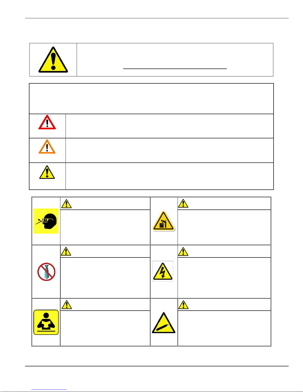
SAFETY ALERT SYMBOL
This symbol is used to call your attention to hazards or unsafe practices which could result in an injury
or property damage. The signal word, defined below, indicates the severity of the hazard. The message
after the signal word provides information for preventing or avoiding the hazard.
DANGER
DANGER:
Indicates an imminently hazardous situation which, if not avoided, could result in death or serious injury.
WARNING
WARNING:
Indicates a potentially hazardous situation which, if not avoided, could result in death or serious injury.
CAUTION
CAUTION:
Indicates a potentially hazardous situation which, if not avoided, may result in minor or moderate injury.
CAUTION may also be used to alert against unsafe practices associated with events that could lead
to personal injury.
WARNING
WARNING
Always wear proper eye protection when
Operating or servicing this equipment.
Failure to wear eye protection could result
in serious eye injury from flying debris.
Heavy Object
To avoid muscle strain or back injury, use lifting
aids and proper lifting techniques when removing
or replacing.
Failure to observe these precautions may result in
injury or property damage.
WARNING
WARNING
Never wear clothing or jewelery that is loose or
That could potentially hang into the equipement
and get caught.
Failure to observe this warning could result in
Severe Injury or death.
Never install or service this machine while
connected to any electrical power source.
Disconnect power by unplugging the press
from its power source.
Failure to observe this warning could result
In severe injury or death.
WARNING
WARNING
Never operate, service, install, or adjust this
machine without proper instruction and without
first reading and understanding the instructions
in this manual and all applicable press and/or
wire processing machine.
manuals.
Never Install or service this machine while
connected to the compressed air source.
Failure to observe this warning could result
In severe injury or death.
Safety Warnings and Information
Doc No: TM-192790001 Release Date: 07-01-02 UNCONTROLLED COPY Page 2 of 20
Revision: G Revision Date: 01-17-14
Page 3
AT-200 Air-Powered Crimping Tool
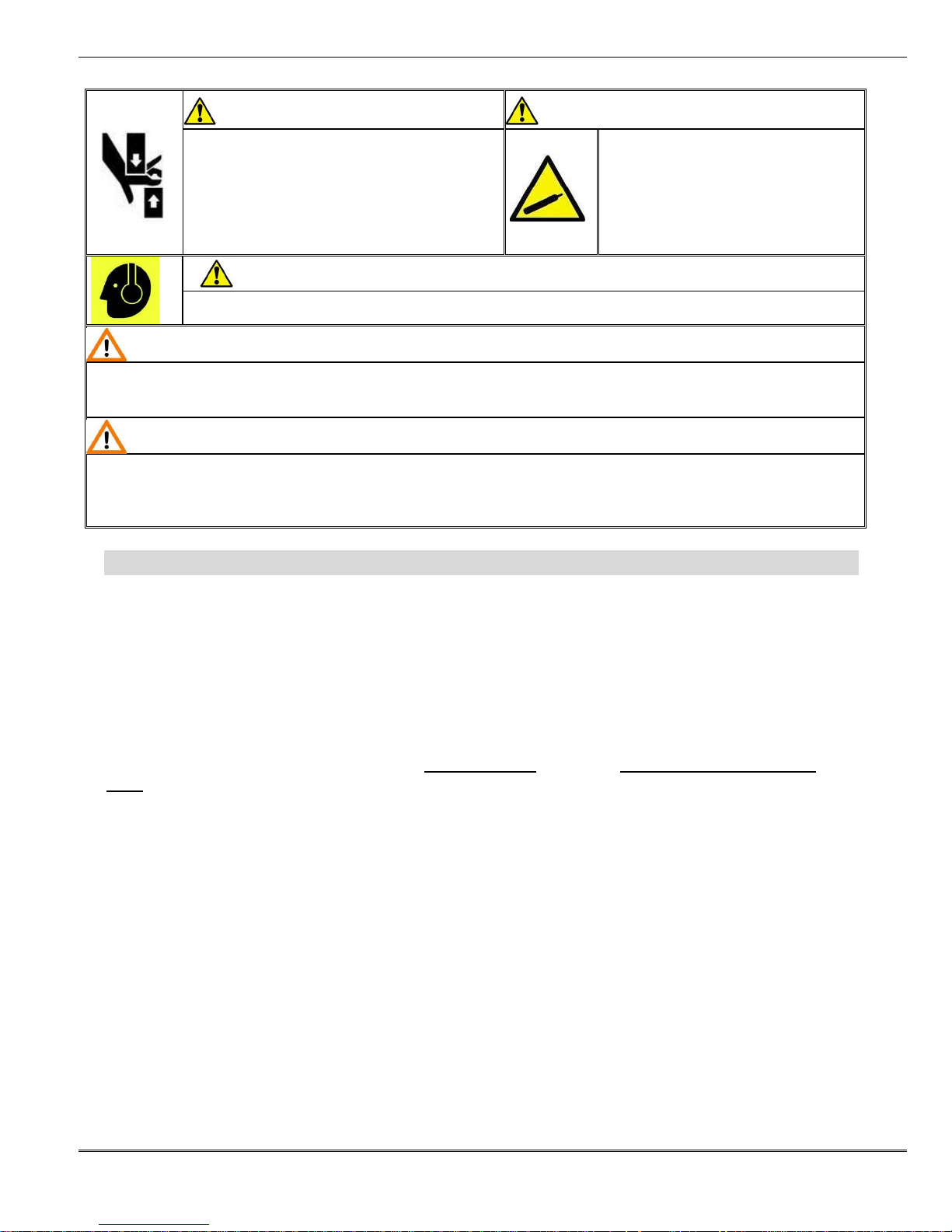
WARNING
WARNING
Never use this machine without guards or safety
devices that are intended
to prevent hands from remaining in the die space.
Failure to observe this warning could result in
Severe injury or death.
Do not use compressed air to clean
this equipment.
The forces created by compressed
air can force debris into the tool.
Failure to observe these precautions may
result in injury or property damage.
WARNING
Always wear proper ear protection when Operating or servicing this equipment.
CAUTION
The Molex at-200 air powered crimping tool is designed to be used with air powered crimp tools heads and tooling supplied by Molex.
Use of tool heads or tooling from any other source may result in damage or injury.
Molex will not be liable for any damage or injury from use of non-Molex components in this tool.
CAUTION
Never perform any service or maintenance other than as described in this manual.
Never modify, alter or misuse this tool
Molex crimp specifications are valid only when used with Molex terminals, applicators and tooling.
Failure to observe this precaution may result in injury and property damage.
Tooling Technical Assistance
Molex offers tooling technical assistance for customers who may need some guidance for tooling adjustments. This
support can be obtained by calling either of the two numbers listed below and asking for the Molex Tooling Group.
Call Toll Free 1-800-786-6539 (US) 1-630-969-4550 (Global).
This assistance is limited to the operation and set-up of a customer’s tool. Questions with regard to Molex connector
products or how to identify the proper tooling and/ or tooling documentation should be directed to your local Molex
personnel or Customer Service Representative.
When calling for service on the press a copy of the Operation Manual and Specific Applicator Tooling Specification
Sheet should be present and a person that is familiar with the applicator should be present. Be sure the following
information is supplied:
1. Customer name
2. Customer address
3. Person to contact such as (name, title, e-mail, and telephone number
4. Applicator order number (Lease number also if applicable)
5. Serial number (Lease number also if applicable)
6. Molex Connector product order number
7. Urgency of request
8. Nature of problem
Molex Application Tooling Group
2200 Wellington Court
Lisle, IL 60532, USA
Tel: +1 (630) 969-4550
Fax:+1 (630) 505-0049
Doc No: TM-192790001 Release Date: 07-01-02 UNCONTROLLED COPY Page 3 of 20
Revision: G Revision Date: 01-17-14
Visit our Web site at http://www.molex.com
Page 4

AT-200 Air-Powered Crimping Tool
Table of Contents
Contents
AT-200 AIR-POWERED CRIMPING TOOL .................................................................................................................. 1
Order No. 19279-0001 ................................................................................................................................................... 1
Safety Warnings and Information .................................................................................................................................. 2
Table of Contents .......................................................................................................................................................... 4
Section 1 ....................................................................................................................................................................... 5
General Description ................................................................................................................................................... 5
1.1 Description .................................................................................................................................................... 6
1.2 Features ........................................................................................................................................................ 6
1.3 Technical Specification .................................................................................................................................. 6
1.4 Delivery Check .............................................................................................................................................. 6
1.5 Tools .............................................................................................................................................................. 6
1.6 Specification Sheets ...................................................................................................................................... 6
Section 2 ....................................................................................................................................................................... 7
2.1 Set-Up ........................................................................................................................................................... 8
2.2 Operation ....................................................................................................................................................... 9
Section 3 ..................................................................................................................................................................... 10
Adjustments ............................................................................................................................................................. 10
3.1 Changing Crimp Tool Heads ....................................................................................................................... 11
3.2 Insulation Support Crimp Adjustment .......................................................................................................... 12
3.3 Insulation Support Crimp Adjustment .......................................................................................................... 12
3.4 Terminal Crimping ....................................................................................................................................... 12
3.5 Maintenance ................................................................................................................................................ 12
3.6 Warranty ...................................................................................................................................................... 13
Section 4 ..................................................................................................................................................................... 14
Parts List and Assemblies ....................................................................................................................................... 14
4.1 19279-0001 Parts List and Assembly Drawings .......................................................................................... 15
4.2 19279-0135 Parts List ................................................................................................................................. 16
4.2 19279-0135 Assembly Drawings ................................................................................................................. 17
4.3 19078-0307 (Optional) Parts List and Assembly Drawings.......................................................................... 18
4.4 64001-4000 (Optional) Parts List and Assembly Drawing ........................................................................... 19
4.5 19279-0099 Parts List and Assembly Drawings .......................................................................................... 20
Doc No: TM-192790001 Release Date: 07-01-02 UNCONTROLLED COPY Page 4 of 20
Revision: G Revision Date: 01-17-14
Page 5

AT-200 Air-Powered Crimping Tool
General Description
1.1 Description
1.2 Features
1.3 Technical Specifications
1.4 Delivery Check
1.5 Tools
1.6 Specification Sheets
Section 1
Doc No: TM-192790001 Release Date: 07-01-02 UNCONTROLLED COPY Page 5 of 20
Revision: G Revision Date: 01-17-14
Page 6

AT-200 Air-Powered Crimping Tool
General Description
1.1 Description
The AT-200 Air-Powered Crimping Tool is a hand
held pneumatic tool weighting less than two pounds.
It is designed to crimp high quality and consistent
crimped terminals. This tool operates on standard
shop air (85 to 95 PSI) and crimps wire ranges from
26 to 8AWG.
1.2 Features
Crimping dies are easily and quickly
interchanged to reduce production down time.
Complete portable system that allows tool to be
moved and stored easily.
Tool may be used as a Potable tool, suspended
over head or bench mounted.
Higher volume output with less operator fatigue.
1.3 Technical Specification
Pneumatic:
Supply Pressure: 100 PSI (6.9 Bars) max
Cycle Time:
15 seconds
Weight
0.9kg (2lbs)
1.4 Delivery Check
Carefully remove the AT-200 Air-Powered
Crimping Tool from its shipping container and
determine that the following items are included in
the package.
19279-0001 Air-Powered Crimping Tool
19279-0140 Air Hose 1/8 NPT Male
TM-192790001 Instruction Manual
1.5 Tools
The following tools are recommended for setup
and adjustments to this tool.
1. Metric standard hex wrench set
2. Inch standard hex wrench set
3. Adjustable wrench
4. Wire stripper / cutter
5. Screw driver
Can Also Be Used With:
19078-0307 Bench Adapter Assembly with Foot
Switch
64001-4000 Electrical Control Box
1.6 Specification Sheets
Molex ships specification sheets with every Air
Crimp Tool Head. These Tool Heads are not
included with the AT-200 Air-Powered Crimp Tool.
They are ordered separately. The specification
sheet contains the following:
Terminal numbers
Wire AWG ranges
Insulation diameter ranges
Strip lengths
Pull Force
Crimp heights
Bell mouth
Bend, twist and roll limits
Tooling parts list and assembly
These are available on the Molex website
(www.molex.com).
Doc No: TM-192790001 Release Date: 07-01-02 UNCONTROLLED COPY Page 6 of 20
Revision: G Revision Date: 01-17-14
Page 7

AT-200 Air-Powered Crimp Tool
2.1 Setup
2.2 Operation
Section 2
Doc No: TM-192790001 Release Date: 07-01-02 UNCONTROLLED COPY Page 7 of 20
Revision: G Revision Date: 01-17-14
Page 8

AT-200 Air-Powered Crimp Tool
FILTER REGULATOR
(NOT SUPPLIED)
FOOT SWITCH
BENCH ADAPTER
TO AIR
SUPPLY
SECURE AIR CRIMPING
TOOL IN POSTION
CONNECT TUBING
FROM FOOT SWITCH
WITHOUT FITTING
Figure 2-2
CONNECT TUBING
FROM FOOT SWITCH
WITH FITTING
(NOT SUPPLIED)
TRIGGER
3/8-16 CAP
SCREW
TRIGGER SAFETY
AIR HOSE
(19279-0140)
FILTER REGULATOR
(NOT SUPPLIED)
TO AIR
SUPPLY
TRIGGER
Figure 2-1
Read the following instructions before attempting to operate this tool.
2.1 Set-Up
1. Connect the air hose to the tool and to the air supply 85 to 95 PSI. Do not exceed 100 PSI. May cause injury
or damage to the tool. Air supply must be equipped with a 1/4NPT air filter /regulator which is not supplied by
Molex. See Figure 2-1. (Available from any Industrial supply co.)
If changing to the Optional bench adapter (Order No. 19078-0307) remove the air hose (Order No. 19279-0140) from
the Air-Powered Crimp Tool and connect the tubing from the footswitch. See Figure 2-2. If using the Optional
Electrical Controls (Order No. 64001-4000), see Appendix A.
Doc No: TM-192790001 Release Date: 07-01-02 UNCONTROLLED COPY Page 8 of 20
Revision: G Revision Date: 01-17-14
Page 9

AT-200 Air-Powered Crimp Tool
SAFETY
(LOCKED)
SAFETY ON TRIGGER
(UNLOCKED)
BASE
CRIMP TOOL
PUSH IN
CRIMP TOOL
Figure 2-3
SAFETY
(LOCKED)
SAFETY ON TRIGGER
(UNLOCKED)
CRIMP TOOL
SQUEEZE HERE
Figure 2-4
SQUEEZE HERE
Note: Always use the safety or disconnect air supply when changing crimping heads.
2.2 Operation
1. For the proper crimping head, use the tool order number specified on the label of connector container.
2. Strip the proper wire to the length specified on the label of connector container or on the air powered crimp
tool head specification sheet.
3. Load the desired terminal into the crimp nest. Insert the properly stripped wire into the terminal barrel.
For the Bench Mount Application
1. Slide the Air Powered Crimp Tool into the base. The safety will bump against the base top and the trigger on
the crimp tool will unlock. See Figure 2-3.
CAUTION: Air-Powered Crimp Tool will not operate if the safety in trigger is locked.
1. Push on the wire to assure it is fully seated in the terminal. Cycle the tool by activating the foot pedal.
2. Remove the crimped terminal. Inspect for proper crimp location.
For Hand Held Application
3. Push on the wire to assure it is fully seated in the terminal.
4. Activate the AT-200 Crimp Tool by sliding the safety on the trigger forward using your thumb and then
squeezing the trigger until the crimp jaws are fully closed. See Figure 2-4.
5. Release the trigger and remove the crimped terminal. Inspect for proper crimp location.
Doc No: TM-192790001 Release Date: 07-01-02 UNCONTROLLED COPY Page 9 of 20
Revision: G Revision Date: 01-17-14
Page 10

AT-200 Air-Powered Crimp Tool
Adjustments
3.1. Changing Crimp Tool Heads
3.2. Insulation Support Crimp Adjustment
(Older style fixed jaw air powered crimp tools heads)
3.3. Insulation Support Crimp Adjustment
(Newer style insertion air powered crimp tools heads)
3.4. Terminal Crimping
3.5. Maintenance
Section 3
Doc No: TM-192790001 Release Date: 07-01-02 UNCONTROLLED COPY Page 10 of 20
Revision: G Revision Date: 01-17-14
Page 11

AT-200 Air-Powered Crimp Tool
TURN
CLOCKWISE
(CW)
CAM
INCORRECT CAM
ALIGNMENT
#1/4-20
HOLE
CORRECT CAM
ALIGNMENT
Figure 3-2
CAM
#1/4-20
HOLE
CRIMPIMG HEAD
JAW ASSY
#1/4-20 SLOTTED
SCREWS (2)
Figure 3-1
CRIMPING HEAD
BUTTS UP
AGAINST STEPS
#1/ 4-20
SCREWS (2)
TERMINAL
LOCATOR
SLIDE IN
POWER UNIT
Figure 3-3
CAUTION: Always disconnect air supply before all maintenance.
3.1 Changing Crimp Tool Heads
1. Disconnect the air supply.
2. Remove the (2) #1 /4-20 slotted screws on both sides of
the power unit. Pull the crimp tool head jaw assembly
out of the tool. See Figure 3-1.
3. Before attempting to replace the dies, make sure the
wedge points of the cam line up with the (2) #1/4-20
holes in the front of power unit. See Figure 3-2.
If the cam is not lined up, use the following procedure.
a) Disconnect the air supply with the cam in the retracted
position trigger is up.
b) Grasp the center section of the cam with a long nose plier
and rotate the cam clockwise (CW) until the center line of the
wedge line up with (2) #1/4-20 holes in power unit. See
Figure 3-2 for the correct alignment.
c) Replace the head before cycling the tool. Be sure both
screws are in place and tightened.
4. To replace the crimp tool head, hold power unit in left hand as
shown in Figure 3-3.
5. Grasp the crimp tool head with the right hand and with the
terminal locator facing you. Slide the crimp tool head assembly
into the body of the power unit until the side plates of the crimp
tool head butt against the steps in the power unit. Be sure the
jaw return springs clear the cam in the power unit. See Figure 3-3.
6. Line up the holes in the crimp tool head with the holes in the housing of the power unit.
7. Replace the (2) #1/4-20 screws and tighten securely. The tool is now ready for use.
Doc No: TM-192790001 Release Date: 07-01-02 UNCONTROLLED COPY Page 11 of 20
Revision: G Revision Date: 01-17-14
Page 12

AT-200 Air-Powered Crimp Tool
LOOSEN THE
M4 SCREW
LUBRICATION POINTS
(BOTH SIDES)
LIGHT OIL (EVERY MONTH
OR 5,000 CRIMPS)
Figure 3-5
3/32” HEX
WRENCH
LUBRICATION POINTS
LIGHT OIL (EVERY MONTH
OR 5,000 CRIMPS)
INSULATION CRIMPING
ADJUSTMENT SCREWS
Figure 3-4
3.2 Insulation Support Crimp Adjustment
(Older style fixed jaw air powered crimp tools heads)
1. The crimp tool heads for the insulated terminals and the
connectors feature an adjustable insulation support crimp to
accommodate varying wire insulation diameters (See Figure
3-4) for old style crimp tool head.
2. The adjustment screw on each crimp head tool is set at the
factory at the M position. This setting will give the best
crimp on most wires. Two other adjustment settings are
available: S, the smallest configuration and L, the largest
configuration.
3. Crimp a terminal or connector and inspect the insulation
support sleeve crimp or configuration. A properly crimped sleeve snugly grasps the wire insulation.
4. If the crimp configuration is too loose, change the adjustment setting by removing the air powered crimp tool
head from the AT-200 and setting adjustment screw to the S position. Re-insert the air powered crimp tool
head into the AT-200 and crimp, and inspect the insulation support sleeve.
5. If crimp configuration is too tight, change adjustment setting by removing the air powered crimp tool head from
the AT-200 and setting adjustment screw to the L position. Re-insert the air powered crimp tool head into the
AT-200 and crimp, and inspect insulation support sleeve.
3.3 Insulation Support Crimp Adjustment
(Newer style jaw air powered crimp tools)
For the new style crimp head tools, if the insulation part of the crimp needs to be adjusted, first loosen the M4 screw
on the bottom tool jaw, then insert a 3/32” Hex wrench (supplied) into the bottom of the lower die. See Figure 3.1. A
clockwise (CW) rotation decreases the insulation crimp while a counter-clockwise (CCW) rotation increases the
insulation crimp. After adjusting retighten the M4 screw.
3.4 Terminal Crimping
Specifications and Instructions for crimping are included with the individual air powered crimp tool heads.
3.5 Maintenance
CAUTION: Always disconnect air supply
before all maintenance.
It is recommended that each operator of the tool
be made aware of, and responsible for, the
following maintenance steps:
1. Remove dust, moisture and other
contaminants with a clean brush, or soft,
lint-free cloth.
2. Do not use any abrasive materials that could damage the tool.
Doc No: TM-192790001 Release Date: 07-01-02 UNCONTROLLED COPY Page 12 of 20
Revision: G Revision Date: 01-17-14
Page 13

AT-200 Air-Powered Crimp Tool
3. Make certain all pins; pivot points and bearing surfaces are protected with a thin coat of high quality machine
oil. Do not oil excessively. This tool needs cleaning and lubrication for a maximum service life of trouble-free
crimping. Using a light oil, such as 30 weight automotive oil on the oil points shown in Figure 3-5, every 5,000
crimps or monthly will significantly enhance the tool life and ensure a stable calibration.
4. When tool is not in use store the tool in a clean, dry area.
3.6 Warranty
This tool is for electrical terminal crimping purposes only. This tool is made of the best quality materials. All vital
components are long-life tested. All tools are warranted to be free of manufacturing defects for a period of 30 days.
Should such a defect occur, we would repair or exchange the tool free of charge. This repair or exchange will not
be applicable to altered, misused or damaged tools.
If seals are damaged the warranty is invalid.
CAUTION: Molex crimp specifications are valid only when used with Molex terminals and tooling.
Doc No: TM-192790001 Release Date: 07-01-02 UNCONTROLLED COPY Page 13 of 20
Revision: G Revision Date: 01-17-14
Page 14

AT-200 Air-Powered Crimp Tool
Section 4
Parts List and Assemblies
4.1 19279-0001 Parts List and Assembly Drawings
4.2 19279-0135 Parts List and Assembly Drawings
4.3 19078-0307 Parts List and Assembly Drawings (Optional)
4.4 64001-4000 Parts List and Assembly Drawings (Optional)
4.5 19279-0099 Parts List and Assembly Drawings
Doc No: TM-192790001 Release Date: 07-01-02 UNCONTROLLED COPY Page 14 of 20
Revision: G Revision Date: 01-17-14
Page 15

AT-200 Air-Powered Crimp Tool
2
6 3 1
4
5
(2)
Figure 4-1
19279-0001-Air Power Crimp Tool Assembly Figure 4-1
Item
Order No.
Engineering No.
Description
Qty
Notes
1
19279-0080
19279-0080
Cam For AT-200 Air Tool
1 2
19279-0135
19279-0135
AT-200 Air Powered Crimping Tool
1
Figure 4-2
3
19279-0140
19279-0140
Air Hose 1/8 NPT Male FTG
1 4
19279-0161
19279-0161
Screw Silver Slotted
2 5
N/A
N/A
#1/4-1/8 Hex Bushing
1** 6
N/A
N/A
#1/4-28 by 3/4 Cup Point SSS
1**
** Available from an industrial supply company such as MSC (1-800-645-7270).
4.1 19279-0001 Parts List and Assembly Drawings
Doc No: TM-192790001 Release Date: 07-01-02 UNCONTROLLED COPY Page 15 of 20
Revision: G Revision Date: 01-17-14
Page 16

AT-200 Air-Powered Crimp Tool
19279-0135-AT-200 Air Powered Crimping Tool Figure 4-2
Item
Order No.
Eng. No.
Description
Qty
1
N/A
N/A
1/4 ID by 3/8 OD by 1/16” Cross Section Buna O-Ring
4**
2
N/A
N/A
5/32 ID by 9/32 OD by 1/16” Cross Section Buna O-Ring
2**
3
N/A
N/A
3/8 ID by 1/2 OD by 1/16” Cross Section Buna O-Ring
2**
4
N/A
N/A
1/2 ID by 11/16 OD by 3/32” Cross Section Buna O-Ring
1**
5
N/A
N/A
1.0 ID by 1-13/16 OD by 3/32” Cross Section Buna O-Ring
4**
6
N/A
N/A
1-5/8 ID by 1-3/4OD by 1/16” Cross Section Buna O-Ring
3**
7
N/A
N/A
.180 OD by .017 WD Torsion Spring
1**
8
N/A
N/A
.455 OD by .038 WD by .625” FL Compression Spring
1**
9
N/A
N/A
Retaining Ring 2.012 OD by .062” Thick
5**
10
N/A
N/A
#4-40 by .50 Long SHCS
1**
11
N/A
N/A
#6-32 by .25” Long Flat Head Phillips
1**
12
N/A
N/A
#6-32 by .88“ Long Flat Head Phillips
2**
13
N/A
N/A
#8-32 by .375” Long Round Head Phillips
2**
14
N/A
N/A
1/16 Diameter by .187” Long Dowel Pin
1**
15
N/A
N/A
1/16 Diameter by .25” Long Dowel Pin
1**
16
N/A
N/A
1/8 Diameter by .75” Long Spring Pin
1**
17
N/A
N/A
3/32 Diameter by .75” Long Dowel Pin
1**
** Available from an industrial supply company such as MSC (1-800-645-7270).
4.2 19279-0135 Parts List
Doc No: TM-192790001 Release Date: 07-01-02 UNCONTROLLED COPY Page 16 of 20
Revision: G Revision Date: 01-17-14
Page 17

AT-200 Air-Powered Crimp Tool
11
12
(2)
Figure 4-2
8
(4)
4 5 5 6 9
9
3
5 6 3
2 2 13
10
7
15
14
16
5
9
(2)
9
9 1 6
17
4.2 19279-0135 Assembly Drawings
Doc No: TM-192790001 Release Date: 07-01-02 UNCONTROLLED COPY Page 17 of 20
Revision: G Revision Date: 01-17-14
Page 18

AT-200 Air-Powered Crimp Tool
3
6 7 4
2
3
5
1
(2)
(2)
Figure 4-3
19078-0307-Optional Bench Adapter Figure 4-3
Item
Order No.
Engineering No.
Description
Qty 1 N/A
N/A
Dual Air Hose (1/8 ID by 8’)
1** 2 N/A
N/A
Air Foot Switch (3B – 30A2 – S)
1**
3
N/A
N/A
1/8” NPT – M Fitting, by 1/8 Barb
3** 4 N/A
N/A
1/8” Close Nipple (M/M)
1** 5 N/A
N/A
Clippard Thread on Hose Clamp
2** 6 N/A
N/A
1/8” Fitting Brass Pipe Tee M/F/F
1** 7 N/A
N/A
1/8” Brass Coupling - 1/8 (F/F)
1**
** Available from an industrial supply company such as MSC (1-800-645-7270).
4.3 19078-0307 (Optional) Parts List and Assembly Drawings
(See ATS-19078-0307 specification sheet for installation)
Doc No: TM-192790001 Release Date: 07-01-02 UNCONTROLLED COPY Page 18 of 20
Revision: G Revision Date: 01-17-14
Page 19

AT-200 Air-Powered Crimp Tool
3
6
4
7
1 2 9 1 5
5
Figure 3
REF
EMERGENCY
STOP
TO AIR
SUPPLY
TO
120 VAC
Figure 4-4
1/4 NPT by 1/4 TUBE
FITTING (REF)
8
64001-4000 Optional Full Cycle/ Pressure Electrical Control Box Figure 4-4
Item
Order No.
Description
Qty
1
64001-4000
Electrical Controls
Ref
2
62500-1265
Power Supply
1
3
63800-8394
Footswitch Assembly
1
4
69018-6237
Power Cord
1
5
N/A
1/4“ OD Tubing
**
6
N/A
1/8 NPT by 1/4 Tube Fitting
**
7
19078-0307
Bench Adapter
Ref
8
19279-0001
Air Power Crimp Tool
Ref
9
N/A
Filter Regulator
Ref
** Available from an industrial supply company such as MSC (1-800-645-7270).
4.4 64001-4000 (Optional) Parts List and Assembly Drawing
(See ATS-640014000 specification sheet for installation)
Doc No: TM-192790001 Release Date: 07-01-02 UNCONTROLLED COPY Page 19 of 20
Revision: G Revision Date: 01-17-14
Page 20

AT-200 Air-Powered Crimp Tool
3
4
2 5 1
Figure 4-5
19279-0099-Trigger Safety Kit Figure 4-5
Item
Order No.
Engineering No.
Description
Qty 1 19279-0203
19279-0203
Pivot Block
1 2 19279-0204
19279-0204
Safety Latch
1
3
63600-0052
63600-0052
Torsion Spring
1 4 N/A
N/A
#4-40 by .50” Long SHCS
1** 5 N/A
N/A
3/32 Diameter by 3/4 Long Dowel Pin
1**
** Available from an industrial supply company such as MSC (1-800-645-7270).
4.5 19279-0099 Parts List and Assembly Drawings
(See ATS-19279-00099 specification sheet for installation)
This assembly is included in the AT-200 Air-Powered Crimp Tool 19279-0001 however for older
models of this tool it is recommended to purchase the Trigger Safety Kit 19279-0099.
Visit our Web site at www.molex.com
Doc No: TM-192790001 Release Date: 07-01-02 UNCONTROLLED COPY Page 20 of 20
Revision: G Revision Date: 01-17-14
 Loading...