

Page 1

Battery Powered Crimping Tool
BATTERY POWERED CRIMPING TOOL
Operation Manual
Order No. 63816-0200 (110 V)
Order No. 63816-0250 (220 V)
Order No: TM-638160200 Release Date: 12.06-07 UNCONTROLLED COPY Page 1 of 33
Revision: E Revision Date: 06-07-12
Page 2

Battery Powered Crimping Tool
Table of Contents
BATTERY POWERED CRIMPING TOOL ........................................................................................................................ 1
Safety Warnings and Information ..................................................................................................................................... 3
SECTION 1 ...................................................................................................................................................................... 7
Description ................................................................................................................................................................................... 7
1.1. Features ....................................................................................................................................................................... 7
1.2. Technical Specifications .............................................................................................................................................. 8
1.3 Delivery Check ............................................................................................................................................................. 8
SECTION 2 ...................................................................................................................................................................... 9
Power Crimp Heads and Adapters............................................................................................................................................... 9
2.1 Comparison Chart - Hand and Power Crimp Tools.................................................................................................... 10
2.2 63816-0600 Power Crimp Adapter for Type 4A Hand Crimp Tools ........................................................................... 11
2.3 63816-0300 Power Crimp Head for Type 2C and 4C Hand Crimp Tools .................................................................. 13
2.4 63816-0800 Power Crimp Head for Type 4D Hand Crimp Tools ............................................................................... 15
2.5 63816-0900 Power Adapter for Type AT Air Crimp Heads ........................................................................................ 18
SECTION 3 .................................................................................................................................................................... 20
Set-Up and Adjustments ............................................................................................................................................................ 20
3.1 Set-Up ........................................................................................................................................................................ 21
3.2 Operation ................................................................................................................................................................... 22
3.3 Preventive Instructions .............................................................................................................................................. 23
SECTION 4 .................................................................................................................................................................... 24
General Terminal Specifications and Crimping Operation ......................................................................................................... 24
4.1 Scope ......................................................................................................................................................................... 25
4.2 Crimping Terminals .................................................................................................................................................... 25
SECTION 5 .................................................................................................................................................................... 26
Preventive Maintenance ............................................................................................................................................................ 26
5.1 Periodic Cleaning ....................................................................................................................................................... 27
5.2 Battery and Charging Unit.......................................................................................................................................... 28
5.3 Disposal ..................................................................................................................................................................... 29
5.4 Warranty .................................................................................................................................................................... 29
SECTION 6 .................................................................................................................................................................... 30
Parts List, Assembly Drawings, and Troubleshooting ................................................................................................................ 30
6.1 Parts List and Assembly Drawings ............................................................................................................................ 31
6.2 Troubleshooting ........................................................................................................................................................ 33
Order No: TM-638160200 Release Date: 12.06-07 UNCONTROLLED COPY Page 2 of 33
Revision: E Revision Date: 06-07-12
Page 3
Battery Powered Crimping Tool
Read
and
understand
all of the instructions and safety information in this
SAFETY ALERT SYMBOL
CAUTION:
WARNING
WARNING
Always
wear proper eye protection when
WARNING
WARNING
Electric shock hazard:
WARNING
WARNING
Pinch points:
Safety Warnings and Information
manual before operating or servicing this tool.
Keep this manual available when using this tool.
Replacement manuals are available for download at no charge at
www.molex.com.
This symbol is used to call your attention to hazards or unsafe practices which could result in an injury
or property damage. The signal word, defined below, indicates the severity of the hazard. The message
after the signal word provides information for preventing or avoiding the hazard.
DANGER:
DANGER
WARNING
Indicates an imminently hazardous situation which, if not avoided, could result in death or serious injury.
WARNING:
Indicates a potentially hazardous situation which, if not avoided, could result in death or serious injury.
CAUTION
Indicates a potentially hazardous situation which, if not avoided, may result in minor or moderate injury.
CAUTION may also be used to alert against unsafe practices associated with events that could lead
to personal injury.
Operating or servicing this tool.
Failure to wear eye protection could result in
serious eye injury from flying debris or hydraulic oil.
Never wear clothing or jewelery that is loose or
That could potentially get caught in this tool.
Failure to observe this warning could result in
Severe Injury or death.
Never operate, service, install, or adjust this
tool without proper instruction and without
first reading and understanding the instructions
in this manual and all applicable manuals.
Always wear proper ear protection when
Operating or servicing this tool.
This tool is not insulated. When using this unit near
energized electrical lines, use proper personal
protective equipment.
Failure to observe this warning could result in
severe injury or death
Keep hands away from the crimping head when
crimping.
Failure to observe this warning could result In
severe injury or death.
Order No: TM-638160200 Release Date: 12.06-07 UNCONTROLLED COPY Page 3 of 33
Revision: E Revision Date: 06-07-12
Page 4
Battery Powered Crimping Tool
WARNING
WARNING
Do not use
compressed air to clean this tool.
WARNING
WARNING
Inspect tool and dies before use. Replace any
CAUTION
Do not operate the tool without the dies. Damage to the ram or crimping head can result.
CAUTION
CA
UTION
CAUTION
Never
perform any service or maintenance other than as described in this manual.
Do not use solvents or flammable liquids
to clean the crimping tool.
Solvents or flammable liquids could ignite and
cause serious injury or property damage.
Do not dispose of the battery in a fire. It will
vent fumes and may explode.
Failure to observe this warning could result in
severe injury from harmful fumes or burns from
flying debris
Do not operate with the crimping head open. Damage to the ram or seals can result.
This tool is not designed for continuous use. After 100 crimping cycles, allow the crimping tool to cool down for 15 minutes.
Do not place the tool in a vise. The crimping tool is designed for hand-held operation only.
This tool may be used in damp or wet environments; however, we recommend air-drying the tool before use if it becomes soaked.
Use this tool for the manufacturer’s intended purpose only.
The forces created by compressed air can
force debris into the tool.
Failure to observe these precautions may
result in injury or property damage.
worn or damaged parts. A damaged or
improperly assembled tool can break and strike
someone nearby.
Failure to observe this warning could result in
severe injury or death.
Failure to observe these precautions may result in injury or property damage
Do not allow anything to contact the battery’s terminals.
Do not immerse the battery in liquid. Liquid may create a short circuit and damage the battery.
If the battery is immersed, contact your service center for proper handling.
Do not place the battery into a pocket, tool pouch, or tool box with conductive objects.
Conductive objects may create a short circuit and damage the battery.
Do not place a battery on moist ground or grass. Moisture may create a short circuit and damage the battery.
Failure to observe these precautions may result in injury or property damage.
Do not store the battery at more than 60 °C (140 °F). Damage to the battery can result.
Do not use another manufacturer’s charger. Other manufacturers’ chargers may overcharge and damage the battery.
Do not attempt to open the battery. It contains no user-serviceable parts.
Failure to observe these precautions may result in injury or property damage.
Never modify, alter or misuse the equipment
Molex crimp specifications are valid only when used with Molex terminals, applicators and tooling.
Failure to observe this precaution may result in injury and property damage.
Order No: TM-638160200 Release Date: 12.06-07 UNCONTROLLED COPY Page 4 of 33
Revision: E Revision Date: 06-07-12
Page 5

Battery Powered Crimping Tool
Tooling Technical Assistance
Molex offers tooling technical assistance for customers who may need some guidance for tooling adjustments. This support
can be obtained by calling either of the two numbers listed below and asking for the Molex Tooling Group.
Call Toll Free 1-800-786-6539 (US) 1-630-969-4550 (Global).
This assistance is limited to the operation and set-up of a customer’s Molex tool. Questions with regard to Molex connector
products or how to identify the proper tooling and/ or tooling documentation should be directed to your local Molex personnel
or Customer Service Representative.
When calling for service on this tool, a copy of the Tooling Manual and Specific Application Tooling Specification (ATS) Sheet
should be present and a person that is familiar with this tool should be present. Be sure the following information is supplied:
1. Customer name
2. Customer address
3. Person to contact such as (name, title, e-mail, and telephone number
4. Power tool order number (Lease number also if applicable)
5. Serial number (Lease number also if applicable)
6. Molex Connector product order number
7. Urgency of request
8. Nature of problem
Molex Application Tooling Group
2200 Wellington Court
Lisle, IL 60532, USA
Tel: +1 (630) 969-4550
Fax:+1 (630) 505-0049
Visit our Web site at http://www.molex.com
Order No: TM-638160200 Release Date: 12.06-07 UNCONTROLLED COPY Page 5 of 33
Revision: E Revision Date: 06-07-12
Page 6

Battery Powered Crimping Tool
Table of Contents
SECTIONS
1. General Description
2. Power Crimp Heads and Adapters
3. Set-up and Adjustments
4. Terminal Specifications and Crimping Operation
5. Preventive Maintenance
6. Parts List, Assembly Drawing, and Troubleshooting
Order No: TM-638160200 Release Date: 12.06-07 UNCONTROLLED COPY Page 6 of 33
Revision: E Revision Date: 06-07-12
Page 7
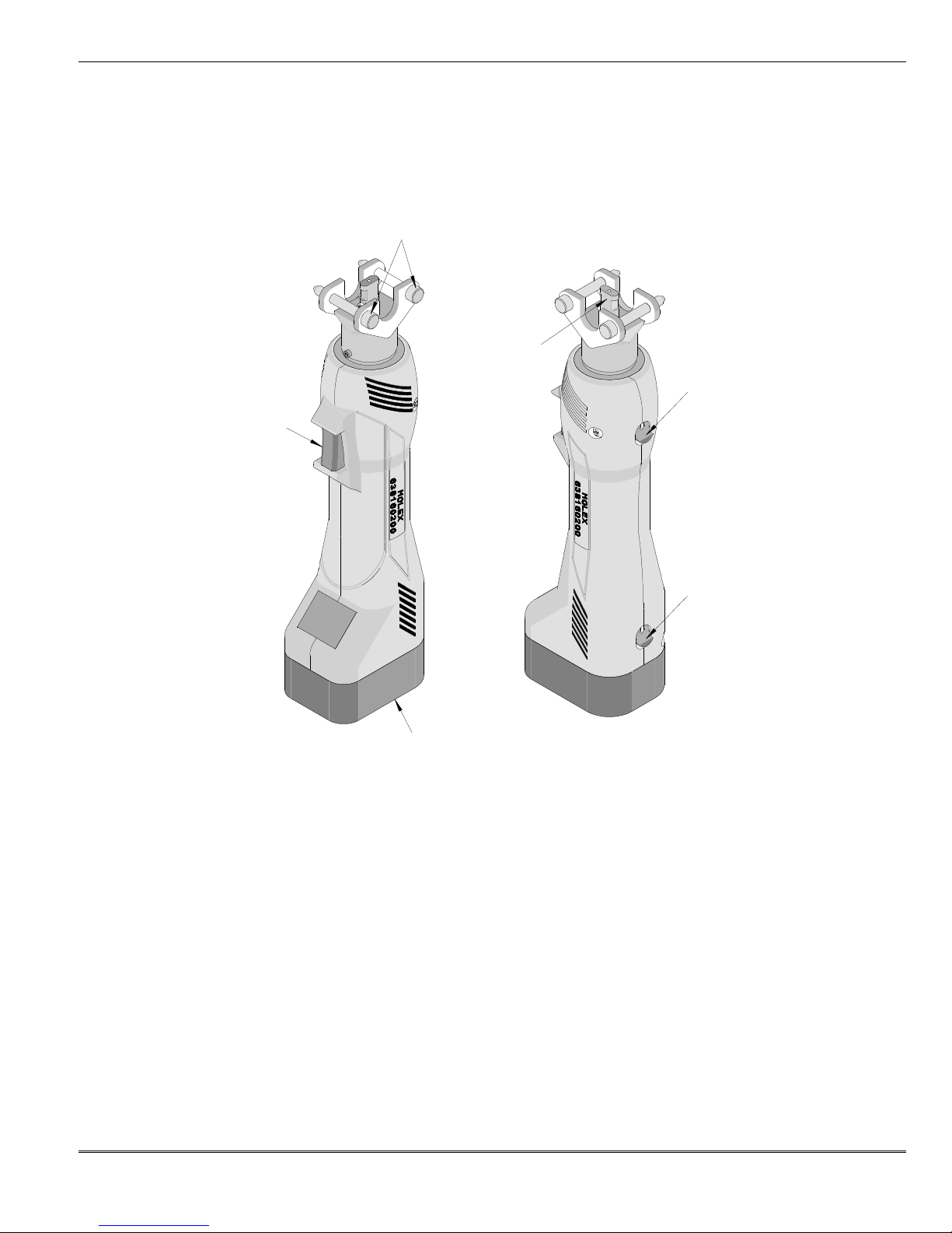
Battery Powered Crimping Tool
LOCKING
TRIGGER
CRIMPING
RECHARGEABLE
UNLOCKING
RETRACTOR
SECTION 1
Principal Mechanical Parts of the 63816-0200 (110 V) and the 63816-0250 (220 V) Battery Powered Tool. Battery charger
not shown.
PINS (2)
HEAD
ADAPTER
SLIDE
SWITCH
(NiCad 9.6V) BATTERY
Figure 1-1
Description
The Molex Battery Powered Tool is designed to crimp terminals with the use of interchangeable modular crimp heads or
power crimp heads, and tool kits. This tool has an automatic retractable system which returns the crimping adapter along
with the crimping dies to the starting position when the maximum force is reached. It is equipped with a special brake that
will stop the forward motion of the crimping dies when the trigger is released. The crimping head can be rotated 360° for
better access in difficult working situations.
1.1. Features
Crimps a wide range of products with interchangeable modular crimp heads or power crimp heads, and tool kits, which
reduce the overall cost and provide production flexibility.
Modular crimp heads or power crimp head and dies are easily and quickly interchanged to reduce production down time.
Complete portable system that allows tool to be moved and stored easily.
Order No: TM-638160200 Release Date: 12.06-07 UNCONTROLLED COPY Page 7 of 33
Revision: E Revision Date: 06-07-12
Page 8

Battery Powered Crimping Tool
1.2. Technical Specifications
Dimensions (with battery)
Length 292.1mm (11.50”)
Width 76.2mm (3.00“)
Depth 50.8mm (2.00“)
Unpacked Weight 1.50kg (3.31lbs)
Production Rate
250 cycles per hour maximum, depending on operator skill and tool kit installed.
Battery
Voltage 9.6V
Capacity 1.3 Ah
Charging Time Approximately 40 minutes, about 15 minutes with fast-charger
Crimps/battery-charge 150 at 10mm
2
Operating Parameters
Maximum Force 15kN (1.7 tonne-force)
Cycle Time 2.0 seconds
Stroke Length 9.00mm (.354”)
Ambient Temperature -20oC to +40oC
Sound Level 75dB (A) in a distance of 1.0m
Vibrations <2.5m/s
2
1.3 Delivery Check
Carefully remove the Battery Powered Tool from its shipping container and determine that the following items are included in
the package.
For the 63816-0200 (110 V):
63816-0200 Battery Crimping Tool
63816-0202 Battery Unit (2)
63816-0210 Battery Charger
Carrying Case
TM-638160200 Operation Manual
For the 63816-0250 (220 V):
63816-0250 Battery Crimping Tool
63816-0202 Battery Unit (2)
63816-0260 Battery Charger
Carrying Case
TM-638160200 Operation Manual
Order No: TM-638160200 Release Date: 12.06-07 UNCONTROLLED COPY Page 8 of 33
Revision: E Revision Date: 06-07-12
Page 9

Battery Powered Crimping Tool
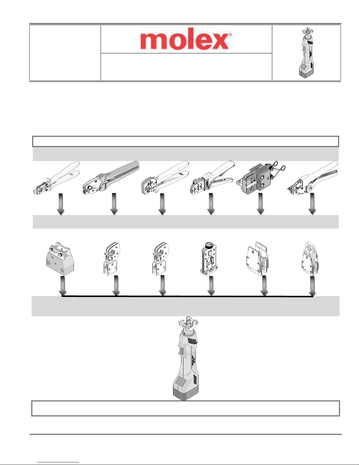
SECTION 2
Power Crimp Heads and Adapters
2.1 Comparison Chart - Hand and Power Tools
2.2 63816-0600 Power Crimp Adapter for Type 4A Hand Crimp Tools
2.3 63816-0300 Power Crimp Head for Type 2C and 4C Hand Crimp Tools
2.4 63816-0800 Power Crimp Head for Type 4D Hand Crimp Tools
2.5 63816-0900 Adapter for Type AT Air Crimp Tools (with 64005-0000 Head for Type RHT
Hand Crimp Tools)
NOTE: Hand Crimp tool “Type” with a pictorial illustration, is displayed on the upper right corner of the Hand Crimp
Tool Specification Sheet (ATS) and in the following pages of this manual.
Order No: TM-638160200 Release Date: 12.06-07 UNCONTROLLED COPY Page 9 of 33
Revision: E Revision Date: 06-07-12
Page 10
Battery Powered Crimping Tool
Type RHT
64005xx00
AT Head
•
Battery
Power and
Comparison
Chart
Crimp Hand Tools
2.1 Comparison Chart - Hand and Power Crimp Tools
SCOPE
Modular crimp heads, power crimp head, adapters, and dies are easily and quickly interchanged between the hand crimp
tools and the battery powered tools. See chart below.
Battery Power Crimp Tool and Adapters for Hand Crimp Tools
Type 4A Type 2C Type 4C Type 4D Type AT
638160600 638160300 638160300 638160800 638160900
Adapter Head Head Head Adapter
63816-0200
Battery Powered Crimp Tool
• See Note
+ 638160900
+ Adapter
NOTE: Un-tooled AT heads are not available separately. Customers can install RHT Tooling into one of their existing AT heads.
Caution must be taken as the markings on the AT head will not match the tooling from an RHT tool for a different terminal.
Order No: TM-638160200 Release Date: 12.06-07 UNCONTROLLED COPY Page 10 of 33
Revision: E Revision Date: 06-07-12
Page 11

Battery Powered Crimping Tool
63816
-
0001
TYPE 4A
63816
-
0600
For
Type 4A Hand Crimp Tools
63816-0600
Power Crimp
Adapter
Application Tooling
TYPE 4A
2.2 63816-0600 Power Crimp Adapter for Type 4A Hand Crimp Tools
Scope
The 63816-0600 Power Crimp Adapter was created for use with the Type 4A Modular Crimp Heads when used with the
Battery Powered Tool (Order No. 63816-0200).
Installation of Type 4A Modular Crimp Heads onto Power Crimp Adapter
To mount the Type 4A Modular Crimp Heads to the 63816-0600 Modular Crimp Adapter, slide the locking pins outward until
they stop. Then place the crimp head in the upper slot and align the holes with the pins. Then, push in the pins until they lock.
See Figure 2-1.
LOCKING PINS (2)
Figure 2-1
Installation of Type 4A Power Crimp Adapter to Battery Powered Crimping Tool
To install the 63816-0600 Power Crimp Adapter onto the 63816-0200 Battery Powered Tool, refer to Section 3, “Set-Up and
Adjustments”.
Operation
1. Load the terminal as described in the Operation section of the specification sheet for the tool.
2. Cycle the Battery Powered Tool to crimp the terminal to the wire. Hold the trigger until the tool completes the cycle.
3. Remove the crimped terminal from the terminal locator by pressing down on the wire stop and gently pulling on the wire.
The terminal locator can be in either position.
4. Visually inspect the crimped terminal for proper crimp location.
WARNING: Never place fingers into the tooling nest.
MODULAR CRIMP
HEAD WITH TOOLING
ADAPTER
Order No: TM-638160200 Release Date: 12.06-07 UNCONTROLLED COPY Page 11 of 33
Revision: E Revision Date: 06-07-12
Page 12

Battery Powered Crimping Tool
Figure 2
-3
LUBRICATION
Figure 2
-2
Item Order No.
Description
Quantity
1 63816-0600
Power Crimp Adapter
1
Maintenance
It is recommended that each operator of the tool be made aware of, and responsible for, the following maintenance steps:
1. This tool was engineered for durability, but like any fine piece of equipment, it needs cleaning and lubrication for a
maximum service life of trouble-free crimping
2. Remove dust, moisture and other contaminants with a clean brush, or soft,
lint-free cloth.
3. Do not use any abrasive materials that could damage the tool.
4. Make certain all pins, pivot points and bearing surfaces in the tool head are
protected with a thin coat of high quality machine oil. Do not oil excessively.
Use light oil, such as SAE 30 weight automotive oil, every 5,000 crimps or
monthly, will significantly enhance the tool life and ensure a stable
calibration. See Figure 2-2 for lubrication points.
5. Store the tool in a clean and dry area when not in use.
Warranty
This tool is for electrical terminal crimping purposes only. This tool is made of
the best quality materials. All vital components are long life-tested. All tools are
POINTS
(BOTH SIDES)
LIGHT OIL
(EVERY MONTH
OR
5,000 CRIMPS)
warranted free of manufacturing defects for a period of 30 days. Should such a
defect occur, we will repair or exchange the tool if it cannot be repaired, free of
charge. This repair or exchange will not be applicable to altered, misused, or damaged tools.
Parts List
1
Order No: TM-638160200 Release Date: 12.06-07 UNCONTROLLED COPY Page 12 of 33
Revision: E Revision Date: 06-07-12
Page 13

Battery Powered Crimping Tool
ANVILS
POWER
Figure
2-4
M4 X 10 LONG
BHCS
M4 X 18 LONG
BHCS
63816-0300
Power Crimp
Head
Application Tooling
Type 2C Type 4C
Hand Crimp Tools
2.3 63816-0300 Power Crimp Head for Type 2C and 4C Hand Crimp Tools
SCOPE
The 63816-0300 Power Crimp Head was created for use with the Type 2C and 4C Crimp Dies and Locator Kits when used
with the Battery Powered Tool (Order No. 63816-0200).
Installation of Type 2C or 4C Crimp Tool Kit Installation into Power Crimp Head
1. Remove the Crimp Tool Kit from the Type 2C or 4C Hand Crimp Tool. To do this, see the instruction sheet included with the
hand crimp tool.
2. To install the Crimp Tool Kit into the Power Crimp Head, follow the steps below:
PUNCHES
1. Insert the Anvils into the bottom slots of the nest. The wire size markings face toward the front of the head, opposite
from the locator pivot shaft. Install the M4 x 10 long BHCS and tighten in place.
2. Insert the Punches into the top slots of the nest with wire size markings to the front. Install the M4 x 18 long BHCS and
tighten in place. See Figure 2-4.
3. Position the locator with the hole over the brass pivot shaft and snap it into place. See Figure 2-5.
WARNING: Never place fingers into the tooling nest.
Power Crimp Head Installation onto Battery Powered Crimping Tool
To install the 63816-0300 Power Crimp Head onto the 63816-0200 Battery Powered Crimping Tool, refer to Section 3, “SetUp and Adjustments”.
CRIMP HEAD
Order No: TM-638160200 Release Date: 12.06-07 UNCONTROLLED COPY Page 13 of 33
Revision: E Revision Date: 06-07-12
Page 14

Battery Powered Crimping Tool
Figure 2
-7
1
M4 X 8 LONG
Item Order No
Description
Quantity
1 63816
-
0300 Power Crimp Head
1
2 63811
-
4773 Universal Locator Mount
1
LUBRICATION
Operation
1. Load the terminal as described in the Operation section of the specification sheet for the tool.
2. Cycle the Battery Powered Tool to crimp the terminal to the wire. Hold the trigger until the tool completes the cycle.
3. Remove the crimped terminal from the terminal locator by pressing down on the wire stop and gently pulling on the wire.
The terminal locator can be in either position.
4. Visually inspect the crimped terminal for proper crimp location.
Maintenance
It is recommended that each operator of the tool be made aware of, and responsible for,
the following maintenance steps:
1. Remove dust, moisture and other contaminants with a clean brush, or soft, lint-free
cloth.
2. Do not use any abrasive materials that could damage the tool.
3. Make certain all pins, pivot points and bearing surfaces in the tool head are
protected with a thin coat of high quality machine oil. Do not oil excessively. This
POINTS
(BOTH SIDES)
LIGHT OIL
(EVERY MONTH
tool was engineered for durability, but like any fine piece of equipment, it needs
cleaning and lubrication for a maximum service life of trouble-free crimping. Use
5,000 CRIMPS)
light oil, such as SAE 30 weight automotive oil, every 5,000 crimps or monthly, will
significantly enhance the tool life and ensure a stable calibration. See Figure 2-6 for
lubrication points.
Figure 2-6
4. Store the tool in a clean and dry area when not in use.
Warranty
This tool is for electrical terminal crimping purposes only. This tool is made of the best quality materials. All vital components
are long life-tested. All tools are warranted free of manufacturing defects for a period of 30 days. Should such a defect
occur, we will repair or exchange the tool if it cannot be repaired, free of charge. This repair or exchange will not be
applicable to altered, misused, or damaged tools.
Parts List
OR
BHCS (REF)
2
Order No: TM-638160200 Release Date: 12.06-07 UNCONTROLLED COPY Page 14 of 33
Revision: E Revision Date: 06-07-12
Page 15

Battery Powered Crimping Tool
Type 4
D Hand Crimp Tools
TOP SLOT
TOP HOOKS
TOP SLOT
OF
LOWER TABS
SQUEEZE
SQUEEZE
LOCATOR
Figure
2-8
MAKE SUR
E
Figure 2
-9
63816-0800
Power Crimp
Head
Application Tooling
2.4 63816-0800 Power Crimp Head for Type 4D Hand Crimp Tools
SCOPE
The 63816-0800 Power Crimp Head was created for use with Type 4D Crimp Dies and Locator when used with the Battery
Powered Tool (Order No. 63816-0200).
Installation for Type 4D Crimp Tooling Installation into Power Crimp Head
First, remove the crimp tooling from the Type 4D Hand Crimp Tool. To do this, see the instruction sheet included with the
hand crimp tool.
To remove the locator from the Power Crimp Head
1. Open the Power Crimp Head to remove the locator.
2. Squeeze gently on the lower area of the locator assembly, shown in Figure 2-8 with your thumb and index finger. The
lower tabs of the locator should disengage from the Power Crimp Head.
3. Lift and pull away from the Power Crimp Head. The top locator hooks should slip out of the top slots easily. See Figure
2-8.
HERE
OF THE
HANDTOOL
HERE
To install the locator in the Power Crimp Head
1. Install the locator assembly.
2. Press the red insert down as far as it will go. See Figure 2-9.
3. The locator goes on the opposite side from the dies with the wire gauge markings.
4. While holding onto the lower part of the locator with your thumb and index finger, insert the
locator top hooks (2) into the Power Crimp Head top slots.
5. Rotate the locator down and press the lower tabs into the two bottom slots of the head. To
secure the locator into place, the lower tabs must snap into place on the head frame.
Removing the Crimp Dies from the Power Crimp Head
1. Open the Power crimp Head.
2. Remove the two M3 BHCS.
3. Remove the crimp dies as shown in Figure 2-10.
4. Make sure all of components removed from the Power Crimp Head are reinstalled into the Power Crimp Head in the same
manner.
THE HANDTOOL
TYPE 4D
CENTER OF LOCATOR
IS IN THE
DOWN POSITION
Order No: TM-638160200 Release Date: 12.06-07 UNCONTROLLED COPY Page 15 of 33
Revision: E Revision Date: 06-07-12
Page 16

Battery Powered Crimping Tool
M3 BHCS
E1
E2
I2
I1
POWER CRIMP HEAD
M3 BHCS
MATCH UP
WIRE GAUGE
LOCKING
Figure 2
-12
KN
URLED
KNOB
Installing the Crimp Dies in the Power Crimp Head
1. Select the desired Type 4D crimping dies.
2. Insert the Anvils or dies (E1 and I1) into the bottom slots of the nest. Install the M3 x 14 long BHCS and lightly tighten in
place.
Note: The tool part number markings on the dies go inward so they will not be visible when installed.
MARKINGS
X 8 LONG
Figure 2-10
X 14 LONG
IDENTIFICATIONS
SHOWING
Figure 2-11
3. Insert the Punches or dies (E2 and I2) into the top slots of the nest. Install the M3 x 8 long BHCS and lightly tighten in
place. See Figure 2-10
4. Make sure the small markings on the individual dies match up and wire gauge identification (AWG) marks should be facing
out and aligned as shown in Figure 2-11.
5.
Note: Make sure the longer screw only goes into the lower dies.
6. Completely close the crimp dies until they are touching, and then securely tighten the M3 BHCS.
Power Crimp Head Installation onto Battery Powered Crimping Tool
To install the 63813-0800 Power Crimp Head onto the 63816-0200 Battery Powered
Tool, refer to Section 3, “Set-Up and Adjustments”.
Adjustments
The crimp height on the 63816-0800 Power Crimp Head can be adjusted, if
necessary. To do this, first measure the conductor crimp height of a crimped
terminal and compare to the crimp specification listed in the product specification for
that terminal. If an adjustment is required, follow the procedure, below:
1. Loosen the locking set screw located just below the knurled knob at the top of
the Power Crimp Head. See Figure 2-12.
2. If the crimp height is too loose, rotate the knob, a small amount, in the counter-
clockwise direction. Crimp another terminal and re-check the crimp height.
3. If the crimp height is too tight, turn the knob clockwise and follow the same procedure.
4. Do this until the proper crimp height is achieved.
5. When the proper crimp height is achieved, lock the set screw.
SET SCREW
Order No: TM-638160200 Release Date: 12.06-07 UNCONTROLLED COPY Page 16 of 33
Revision: E Revision Date: 06-07-12
Page 17

Battery Powered Crimping Tool
2
Figure 2
-11
Item Order No
Description
Quantity
1 63816
-
0800 Power Crimp Head (for style 4D crimp tools)
1
2 63816
-
0801 Return Spring
2
LUBRICATION
Operation
1. To load a terminal and position the wire in the terminal in the Power Crimp
Head, follow the loading procedure as explained in the Hand Crimp Tool
Specification sheet.
2. Crimp the terminal by squeezing the trigger on the side of the battery actuator
until the tool cycles and returns and the jaws open.
3. Remove the terminal from the locator and inspect the crimp for proper quality.
WARNING: Never place fingers into the tooling nest.
Maintenance
It is recommended that each operator of the tool be made aware of, and
responsible for, the following maintenance steps:
This tool was engineered for durability, but like any fine piece of equipment, it
(BOTH SIDES)
(EVERY MONTH
needs cleaning and lubrication for a maximum service life of trouble-free crimping
Remove dust, moisture and other contaminants with a clean brush, or soft, lint-
5,000 CRIMPS)
free cloth.
Do not use any abrasive materials that could damage the tool.
Use light oil, such as SAE 30 weight automotive oil, every 5,000 crimps, or
Figure 2-13
monthly, will significantly enhance the tool life and ensure a stable calibration.
Make certain all sliding surfaces in the tool head are protected with a thin coat of high quality machine oil. See Figure 2-13
for lubrication points. Do not oil excessively and wipe excess oil from the tool frame when complete.
Store the tool in a clean and dry area when not in use.
Warranty
This tool is for electrical terminal crimping purposes only. This tool is made of the best quality materials. All vital components
are long life-tested. All tools are warranted free of manufacturing defects for a period of 30 days. Should such a defect
occur, we will repair or exchange the tool if it cannot be repaired, free of charge. This repair or exchange will not be
applicable to altered, misused, or damaged tools.
Parts List
POINTS
LIGHT OIL
OR
Order No: TM-638160200 Release Date: 12.06-07 UNCONTROLLED COPY Page 17 of 33
Revision: E Revision Date: 06-07-12
2
1
Page 18

Battery Powered Crimping Tool
Type RHT
Type AT
AT CRIMP
HEAD
SLOTTED SCREW (2)
Figure 2
-14
AT HEAD
RHT CRIMP
TOOLING KIT
63816-0900
Power Adapter
Application Tooling
Hand Crimp Tools and Air Crimp Heads
2.5 63816-0900 Power Adapter for Type AT Air Crimp Heads
(With 64005-0000 Head for Type RHT Hand Crimp Tools)
SCOPE
The 63816-0900 Power Adapter was created to adapt the 64005 and 64007 series Type AT Crimp Heads for use in the
63816-0200 Battery Powered Tool.
The addition, customers who have Type RHT hand crimp tools along with a Type AT Crimp Head, can load the RHT dies
and locator into the AT crimp head and then in the Battery Powered Tool
Installation
Type AT Air Crimp Head Installation into AT Power Adapter
Install the AT Air Crimp Head onto the AT Power Adapter as shown in Figure 2-15.
Type RHT Crimp Tool Kit into AT Head and AT Power Adapter (One AT Crimp Head required)
Remove the Crimp Tooling Kit from the Type RHT Hand Crimp Tool. To do this, see the instruction sheet included with the
hand crimp tool.
1. Install the RHT tooling kit with locator, into the AT Power Crimp Head. See Figures 2-14.
2. Then install the crimp head onto the AT Power Adapter. This is a typical Type RHT Crimp Tooling Kit arrangement in AT
Head. See Figure 2-15.
For specific tooling, see the specification sheet that is included with the RHT tool.
WARNING: Never place fingers into the tooling nest.
AT CRIMP HEAD
ADAPTER
Figure 2-15
Order No: TM-638160200 Release Date: 12.06-07 UNCONTROLLED COPY Page 18 of 33
Revision: E Revision Date: 06-07-12
Page 19

Battery Powered Crimping Tool
Figure 2
-17
1
Item Order No.
Description
Quantity
1 63816
-
0900 Power Crimp Adapter
1
2 19279
-
0161 Slotted Screw
2
LUBRICATION
Figure 2
-16
Installation of Power Crimp Head with Power Adapter to the Battery Powered Crimping Tool
To install the 63816-0900 Power Adapter onto the 63816-0200 Battery Powered Tool, refer to Section 4, “Set-Up and
Adjustments”.
Operation
1. To load a terminal and position the wire in the terminal in the Power Crimp Head,
follow the loading procedure as explained in the AT Crimp Head (or RHT Hand Crimp
Tool) instruction sheet.
2. Crimp the terminal by squeezing the trigger on the side of the battery actuator until
(BOTH SIDES)
(EVERY MONTH
the tool cycles and returns and the jaws open.
3. Remove the terminal from the locator and inspect the crimp for proper quality.
5,000 CRIMPS)
Maintenance
It is recommended that each operator of the tool be made aware of, and responsible for,
the following maintenance steps:
6. This tool was engineered for durability, but like any fine piece of equipment, it needs
cleaning and lubrication for a maximum service life of trouble-free crimping
7. Remove dust, moisture and other contaminants with a clean brush, or soft, lint-free
cloth.
8. Do not use any abrasive materials that could damage the tool.
9. Make certain all pins, pivot points and bearing surfaces in the tool head are protected with a thin coat of high quality
machine oil. Do not oil excessively. Use light oil, such as SAE 30 weight automotive oil, every 5,000 crimps or
monthly, will significantly enhance the tool life and ensure a stable calibration. See Figure 2-16 for lubrication points.
10. Store the tool in a clean and dry area when not in use.
Warranty
This tool is for electrical terminal crimping purposes only. This tool is made of the best quality materials. All vital components
are long life-tested. All tools are warranted free of manufacturing defects for a period of 30 days. Should such a defect
occur, we will repair or exchange the tool if it cannot be repaired, free of charge. This repair or exchange will not be
applicable to altered, misused, or damaged tools.
Parts List
POINTS
LIGHT OIL
OR
Order No: TM-638160200 Release Date: 12.06-07 UNCONTROLLED COPY Page 19 of 33
Revision: E Revision Date: 06-07-12
2
Page 20

Battery Powered Crimping Tool
SECTION 3
Set-Up and Adjustments
3.1. Set-up
3.2. Operation
3.3. Preventive Instructions
Order No: TM-638160200 Release Date: 12.06-07 UNCONTROLLED COPY Page 20 of 33
Revision: E Revision Date: 06-07-12
Page 21

Battery Powered Crimping Tool
Figure
3-1 Replacing Power or Modular Crimp Heads
63806
-
0900 (Type
AT)
63816
-
0600 (Type 4A)
63816
-
0300 (Type 2C OR 4C)
63816
-
0800 (Type 4D)
TYPE
2C OR 4C
LOCKING
TYPE
2C OR
4C
BATTERY
CRIMP HEAD
LOCKING
RETRACT
TYPE AT
SLOTTED
BATTERY
63816
-
0900
LOCKING
RETRACT
YOKE
TYPE AT
TYPE 4A
RETRACT
LOCKING
BATTERY
TYPE 4A
63816
-
0600
LOCKING
TYPE
4D
BATTERY
TYPE 4
D
CRIMP HEAD
LOCKING
RETRACT
YOKE
3.1 Set-Up
MODULAR CRIMP
HEAD
MODULAR CRIMP
HEAD
WITH TOOLING
PINS (2)
SCREWS (2)
LATCH
PINS (2)
ADAPTER
POWERED TOOL
SLIDE
POWER CRIMP HEAD
NO TOOLING SHOWN
PINS (2)
POWER CRIMP HEAD
NO TOOLING SHOWN
ADAPTER
YOKE
POWERED
TOOL
SLIDE
YOKE
PINS (2)
ADAPTER
POWERED TOOL
Before starting any work on electrical applications, make sure there are no live cables or parts in the immediate area of the user.
Order No: TM-638160200 Release Date: 12.06-07 UNCONTROLLED COPY Page 21 of 33
Revision: E Revision Date: 06-07-12
SLIDE
ADAPTER
POWERED TOOL
SLIDE
PINS (2)
Page 22

Battery Powered Crimping Tool
TYPE 4A
WITH LOCATOR
HOLD TRIGGER
TYPE 4A
WITH LOCATOR
TERMINAL
HOLD TRIGGER
TERMINAL
TYPE 2C AND 4C
WITH LOCATOR
Warning: Remove the battery from the crimping tool before installing and removing dies in the crimp head.
1. Select the appropriate modular crimp head or power crimp head with the proper tooling kit inserted for the application
needed. The Modular Crimp Head with the Battery Powered Crimp Adapter or the Power Crimp Head are sold separately.
2. Remove the locking pins (2) from the battery powered crimp yoke.
3. Place the modular crimp head into the yoke and push down until it engages into the slot of the adapter. The Power Crimp
Heads do not require a separate Power Crimp Adapter.
4. Replace the locking pins (2) making sure the modular crimp head or the Power Crimp Head are secure. The locking pins can
be inserted from either side of the yoke. See Figure 3-1.
WARNING: Electric shock hazard:
This tool is not insulated. When using this unit near energized electrical lines, use proper personal protective
equipment.
Failure to observe this warning could result in severe injury or death
WARNING: Wear eye protection when operating or servicing this tool.
Failure to wear eye protection could result in serious eye injury from flying debris or hydraulic oil.
3.2 Operation
MODULAR CRIMP HEAD
AND WIRE
IN PLACE
POWER CRIMP
ADAPTER
AND WIRE
IN PLACE
DOWN
Figure 3-2
DOWN
1. Insert the proper terminal or connector into the tooling nest and push on the trigger in the handle just enough so the dies
contact the terminal or connector securely. Release the trigger. This allows the operator to make adjustments to the
connector before the final termination. See Figure 3-2.
2. Insert the wire or cable into the terminal. Push on the wire or cable to assure it is fully seated in the terminal.
3. Hold the trigger down again until the crimping tool achieves pressure relief, which is accompanied by an audible “pop”.
The crimping operation can be interrupted at any time during the cycle by releasing the trigger.
4. The crimping cycle is complete when the dies are completely closed and the maximum crimping force is reached. The
dies will automatically release and will go back to their original position.
Note: In case of an error or emergency, the ram can be retracted before the crimping cycle is complete. To do this push
the retractor slide towards the battery. See Figure 3-1.
POWER CRIMP HEAD
Order No: TM-638160200 Release Date: 12.06-07 UNCONTROLLED COPY Page 22 of 33
Revision: E Revision Date: 06-07-12
Page 23

Battery Powered Crimping Tool
Warning: An incomplete crimp can cause a fire.
Use proper die, connector, and cable combinations. Improper combinations can result in an incomplete crimp.
The relief valve will sound to indicate a completed crimp. If you do not hear the sound of the relief valve, the crimp is
not complete. Failure to observe these warnings could result in severe injury or death.
3.3 Preventive Instructions
WARNING: Do not dispose of the battery in a fire. It will vent fumes and may explode.
Failure to observe this warning could result in severe injury from harmful fumes or burns from flying debris
WARNING: Inspect tool and dies before use. Replace any worn or damaged parts. A damaged or improperly
assembled tool can break and strike someone nearby. Failure to observe this warning could result in severe injury or
death.
CAUTION:
Do not operate the tool without the dies. Damage to the ram or crimping head can result.
Do not operate with the crimping head open. Damage to the ram or seals can result.
This tool is not designed for continuous use. After 100 crimping cycles, allow the crimping tool to cool down for 15 minutes.
Do not place the tool in a vise. The crimping tool is designed for hand-held operation only.
This tool may be used in damp or wet environments; however, we recommend air-drying the tool before use if it becomes
soaked.
Use this tool for the manufacturer’s intended purpose only.
Failure to observe these precautions may result in injury or property damage.
CAUTION:
Do not allow anything to contact the battery’s terminals.
Do not immerse the battery in liquid. Liquid may create a short circuit and damage the battery.
If the battery is immersed, contact your service center for proper handling.
Do not place the battery into a pocket, tool pouch, or tool box with conductive objects.
Conductive objects may create a short circuit and damage the battery.
Do not place a battery on moist ground or grass. Moisture may create a short circuit and damage the battery.
Failure to observe these precautions may result in injury or property damage.
Avoid dropping this tool. Extreme shock may damage the internal mechanism and result in malfunction of the tool.
Order No: TM-638160200 Release Date: 12.06-07 UNCONTROLLED COPY Page 23 of 33
Revision: E Revision Date: 06-07-12
Page 24

Battery Powered Crimping Tool
SECTION 4
General Terminal Specifications and Crimping Operation
4.1. Scope
4.2. Crimping terminals
Order No: TM-638160200 Release Date: 12.06-07 UNCONTROLLED COPY Page 24 of 33
Revision: E Revision Date: 06-07-12
Page 25

Battery Powered Crimping Tool
Wire Size (AWG)
Tooling Color Code
*UL –
486A **UL –
486C ***MIL
-T-
7928
22 8 8
20 13 10
18 20 10
16 30 15
14 50 25
12 70 35
10 80 40
8 Red 90 45 225
6 Blue 100 50 300
4 Yellow
140 - 400
2 Red 180 - 550
1 Blue 200 - 650
1/0 Blue 250 - 700
2/0 Yellow
300 - 750
3/0 Red 350 - 825
4/0 Blue 450 - 875
4.1 Scope
This tool is designed to crimp various Molex terminals and splices using our offering of crimping heads.
Testing
Mechanical
The tensile test, or pull test, is a means of evaluating the mechanical properties of the crimped connections. The following
charts show the UL specifications for various wire sizes. The tensile strength is shown in pound-force, which indicates the
minimum acceptable force to break or separate the terminal from the conductor.
*UL – 486A – Terminals (Copper Conductors Only)
**UL – 486C – Butt Slices and Parallel Slices (Over 6 AWG use 486A values)
***MIL-T-7928 - Military Approved Terminals only as listed
4.2 Crimping Terminals
Specifications and Instructions for crimping are included with the individual Hand Tool / Modular Crimp Heads.
These documents are called the Application Tooling Specification (ATS) Sheets.
These come with complete Hand Tools / Module Crimp Heads. If another copy is needed search on the www.Molex.com for
the hand tool order number desired. In the section Specification & Other Documents click on the Application Tooling
Specification (PDF) (ATS-EN).
Order No: TM-638160200 Release Date: 12.06-07 UNCONTROLLED COPY Page 25 of 33
Revision: E Revision Date: 06-07-12
Page 26

Battery Powered Crimping Tool
SECTION 5
Preventive Maintenance
5.1. Periodic Cleaning
5.2. Storage
5.3. Battery and Charging Unit
5.4. Disposal
5.5. Warranty
Order No: TM-638160200 Release Date: 12.06-07 UNCONTROLLED COPY Page 26 of 33
Revision: E Revision Date: 06-07-12
Page 27

Battery Powered Crimping Tool
Days of the Week
MON
TUE WED
THU
FRI SAT SUN
1
2
3
4
Cleaning
Daily
After use
Lubrication
(2) bolts in crimping head
Use SAE 10W
Hydraulic oil
5.1 Periodic Cleaning
Always clean tool after use and keep moving parts clear of dirt and debris.
This tool is basically maintenance free, only the bolt joints at the crimping head have to be oiled regularly.
Before use:
Inspect dies for wear or damage such as cracks, gouges, or chips.
Inspect the tool for damage or leaks. If damage is detected, return the tool to a Molex representative for inspection.
After use:
Wipe all tool surfaces clean with a damp cloth and mild detergent. Excessive dirt and grit can contribute to the premature
wear of the tool’s internal mechanical parts. If this tool becomes dirty with excessive debris it may jam and become damaged
during operation.
Fully retract the ram. Place the tool in the carrying case. Store in a cool, dry place.
Charge the battery.
WARNING: Do not use compressed air to clean this tool. The forces created by compressed air can force debris
into the tool. Failure to observe these precautions may result in injury or property damage.
WARNING: Do not use solvents or flammable liquids to clean the crimping tool. Solvents or flammable liquids
could ignite and cause serious injury or property damage.
Monthly:
Thoroughly clean all surfaces.
A routine should be established to keep the tool as free from dirt as possible.
An example of a maintenance chart is shown below. Copy and use this chart to track the maintenance of this crimping tool or
use this as a template to create your own schedule or use your company’s standard chart, if applicable.
Preventive Maintenance Chart
CHECK SHEET MONTH YEAR _________
Week
Daily
Use
Solution
Schedule should be adjusted up or down depending on usage. Molex recommends that a log of preventive maintenance be
kept with the tool.
Order No: TM-638160200 Release Date: 12.06-07 UNCONTROLLED COPY Page 27 of 33
Revision: E Revision Date: 06-07-12
Page 28

Battery Powered Crimping Tool
Red Charging Unit is ready to operate.
Battery defect
Charging Battery is out of order.
Green
--- Charging cycle stared.
Battery fully charged. Charging unit switches automatically
Yellow
--- Battery is at least 90% charged. Charging can be terminated.
If the Right LED does not light up, the circuit of the battery
5.2 Battery and Charging Unit
WARNING: Do not dispose of the battery in a fire. It will vent fumes and may explode.
Failure to observe this warning could result in severe injury from harmful fumes or burns from flying debris
CAUTION:
Do not store the battery at more than 60 °C (140 °F). Damage to the battery can result.
Do not use another manufacturer’s charger. Other manufacturers’ chargers may overcharge and damage the battery.
Do not attempt to open the battery. It contains no user-serviceable parts.
Failure to observe these precautions may result in injury or property damage.
CAUTION:
Do not allow anything to contact the battery’s terminals.
Do not immerse the battery in liquid. Liquid may create a short circuit and damage the battery.
If the battery is immersed, contact your service center for proper handling.
Do not place the battery into a pocket, tool pouch, or tool box with conductive objects.
Conductive objects may create a short circuit and damage the battery.
Do not place a battery on moist ground or grass. Moisture may create a short circuit and damage the battery.
Failure to observe these precautions may result in injury or property damage.
The charging unit is run with a nominal voltage of 110V or 220V (for Europe) and a frequency of 50-60Hz . New batteries
must be charged before use. To remove the battery from the crimping tool push down on the battery lock and pull out. See
Figure 5-1. To charge the battery plug in the charging unit into a power source and slide the battery upside down into the
charging unit. The normal charging time is about 40 minutes. The charging level of the battery cartridge can be checked by
the right LED (multicolor) of the charging unit.
Color Left LED (red) Right LED (multicolor)
Red
Flashing
Green
Flashing
--- Unit not powered
New or unused battery’s
voltage capacity is insufficient.
--Battery can stay in charge for an indefinite time without being damaged.
Battery too hot or too cold. Remove the battery.
Safety components possibly defected.
into a maintaining level.
is disconnected or the battery is incorrectly polarized.
Notes:
If the standard capacity of the battery is not achieved, it does not mean that the battery is faulty. The full capacity of the
battery can be achieved after 3 charging/discharging cycles.
1. If there is a noticeable decrease in speed of the crimping tool the battery should be recharged. Charge the battery at room
temperature between 10°C-40°C (50°F-104°F).
2. The battery should be charged before storing.
Order No: TM-638160200 Release Date: 12.06-07 UNCONTROLLED COPY Page 28 of 33
Revision: E Revision Date: 06-07-12
Page 29

Battery Powered Crimping Tool
PUSH DOWN
LOCK
Figure 5
-1
BATTERY
Cautions:
1. Charging a battery which has been used recently or in the sun or a long period of time the right LED might flash red
(battery temperature) greater than 65°C (149°F). In this case let the battery cool down and try again.
2. Charging the battery at low temperatures under 5°C (41°F) is not possible. The battery temperature must be warmed up
before starting the battery cycle again.
3. Do not expose the charging unit to rain or snow.
4. Do not charge the battery in or around explosive materials or gases.
5. Do not use any other (dry or car) battery with the charging unit or the
crimping tool.
6. Do not use the cord as a handle to carry the battery unit.
7. Do not pull the cord out of a wall socket with force.
8. Do not pull the plug of the charging unit until after the battery has been
charged.
9. Do not insert foreign objects into the ducts of the charging unit.
10. Do not disassemble the charging unit.
11. Do not place the battery in your pocket or a tool box, if there are conductive
materials such as coins, keys, tools or other metallic parts, they may cause
injury or property damage.
5.3 Disposal
ON BATTERY
When this tool is no longer operating properly the different components of this tool
will need to be disposed of separately.
UNIT
1. The battery must be disposed of according to the Rechargeable Battery
Recycling Corporation (RBRC) in the USA, or other applicable guidelines in
other countries.
2. The remaining parts of this tool must be disposed of according to the
domestic environmental standards or the Environmental Protection Agency
(EPA) in the USA, or other applicable guidelines in other countries.
3. Because of possible environmental damage, we recommend disposal of the tool by a professional company.
Do not dispose of this tool in your residential or commercial waste, as it would be hazardous to the environment.
5.4 Warranty
All tools are warranted to be free of manufacturing defects for a period of 30 days. Should such a defect occur, we will repair
or exchange the tool free of charge. This repair or exchange will not be applicable to altered, misused, or damaged tools.
This tool is designed for hand use only. Any clamping, fixturing, or use of handle extensions voids this warranty. After one
year Molex recommends the crimping tool be returned to a Molex representative for inspection. Only the heads of the
crimping tool are permitted to be changed by the operator.
Do not damage the seals of this tool.
If seals are damaged the warranty is void.
CAUTION: Molex crimp specifications are valid only when used with Molex terminals and tooling.
Order No: TM-638160200 Release Date: 12.06-07 UNCONTROLLED COPY Page 29 of 33
Revision: E Revision Date: 06-07-12
Page 30

Battery Powered Crimping Tool
SECTION 6
Parts List, Assembly Drawings, and Troubleshooting
6.1. Parts List and Assembly Drawing
6.2. Troubleshooting
Order No: TM-638160200 Release Date: 12.06-07 UNCONTROLLED COPY Page 30 of 33
Revision: E Revision Date: 06-07-12
Page 31

Battery Powered Crimping Tool
3
Figure 6
-1
1
Item Order No
Description
Quantity
1 63816
-
0200 or
63816
-
0250 Battery Powered Tool (110 V) or
Battery Powered Tool (220 V)
1
2 63816
-
0001 Modular Crimp Head Locking Pins
2
3 63816
-
0202 Batt
ery Unit
2
4 63816
-
0210 or
63816
-
0260 Battery Charger
(110 V) or
(220 V)
Not Shown
1
Applications for the Battery Powered Tool
Crimp Head Order No.
Adapter Order No.
Adapter Description
638xx
-
xx70
6400x
-
xx00
63816
-
0300
63816
-
0800
6.1 Parts List and Assembly Drawings
Item No. 4 Not Shown
Note:
The following Modular Crimp Heads and Battery Powered Crimp Adapters are sold separately and are not included with the
63816-0200 (110 V) or the 63816-0250 (220 V) Battery Powered Tool.
The chart below shows all applications for the Battery Powered Tool. See Figure 6-2 and 6-3.
2
(Sold separately)
Figure 6-2 Modular
Figure 6-3 Power
(Type 4A)
(AT)
(Type 2C or 4C)
(Type 4D)
Order No: TM-638160200 Release Date: 12.06-07 UNCONTROLLED COPY Page 31 of 33
Revision: E Revision Date: 06-07-12
Tool Order no. Tool Description
63816-0200 (110 V)
or
63816-0250 (220 V)
63816-0200 (110 V)
or
63816-0250 (220 V)
Battery Power Tool
Battery Power Tool
(Sold separately)
63816-0600
63816-0900
N/A N/A
(Sold separately)
Battery Power
Crimp Adapter
Page 32

Battery Powered Crimping Tool
Figure 6
-
2 Modular Crimp Head
Figure 6
-
3 Power Crimp
Head
TYPE 4A
LOCKI
NG
BATTERY
TYPE 4A
63816
-
0600
LOCKING
PINS (2)
TYPE
4D
BATTERY
TYPE 4D
LOCKING
TYPE
2C or 4
C
BATTERY
TYPE 2C OR 4C
LOCKING
TYPE
AT
SLOTTED
BATTERY
TYPE AT
63816
-
0900
LOCKING
MODULAR
CRIMP HEAD
WITH TOOLING
SCREWS (2)
ADAPTER
PINS (2)
POWERED TOOL
PINS (2)
MODULAR
CRIMP HEAD
WITH TOOLING
ADAPTER
POWERED TOOL
POWER CRIMP HEAD
(NO TOOLING
SHOWN)
POWER CRIMP HEAD
(NO TOOLING
SHOWN)
PINS (2)
Order No: TM-638160200 Release Date: 12.06-07 UNCONTROLLED COPY Page 32 of 33
Revision: E Revision Date: 06-07-12
PINS (2)
POWERED
TOOL
POWERED
TOOL
Page 33

Battery Powered Crimping Tool
Symptom
Cause
Solution
Dirt, contaminants, etc.,
Battery unit contacts corroded.
Clean contacts with pencil eraser or
contact cleaner
Battery unit contacts damaged.
Reform the contacts.
Tool parts worn or damaged.
Contact a Molex representative.
LED glows for
6.2 Troubleshooting
Make sure the battery is charged before toubleshooting this tool.
Tool is inoperative.
Dies stop
during operation.
20 seconds.
in ram area of tool.
Battery charge is low.
Battery charge is low. Charge or replace battery unit.
Visit our Web site at http://www.molex.com
Clean the tool.
Charge or replace battery unit.
Order No: TM-638160200 Release Date: 12.06-07 UNCONTROLLED COPY Page 33 of 33
Revision: E Revision Date: 06-07-12
 Loading...