

Page 1
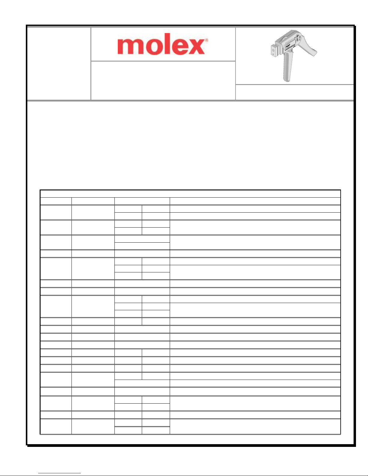
IDT Manual Hand Tool
IDT
Manual
Hand Tool
Application Tooling
Specification Sheet
Order No. 63600-0478
Change Head List
Order No.
Engineering No.
Connector Series No.
Connector Description
11-21-5196
AM60116
7674
7475
KK® IDT Double Cantilever Contact 3.96mm (.156") Pitch, 2 to 16 Circuits.
40791
40915
IDT 3.96mm (.156") Pitch, 2 to 24 Circuits
11-21-5197
AM60115
7720
7720S
KK ® IDT Double Cantilever Contact, 2.54mm (.100") Pitch,
2 to 28 Circuits.
40555
11-21-8365
AM60519
7720
KK ® IDT Double Cantilever Contact, 2.54mm (.100") Pitch,
2 to 28 Circuits.
40555
11-21-9756
AM60512A
70156
5.08mm ( .200") Pitch , Female Type IDT Connector
11-31-3337
AM60571
87259
87568
Mill-Grid™ IDT 2.00mm (.079") Pitch Cable-to-Board, 10 to 50 Circuits.
70625
71247
MX-50™ 1.27mm (.050") Pitch Slimline Ribbon Cable,
6 to 64 Circuits.
70121
71898
11-31-3339
AM60539
70121
MX-50™ 1.27mm (.050") Pitch Slimline Ribbon Cable, 6 to 64 Circuits.
11-31-3340
AM60575
Cable Shear
11-31-4652
AM60577
5320
40312
QF-50™ 2.54mm (.100") Pitch Receptacle 10 to 64 Circuits.
70625
71247
MX-50™ 1.27mm (.050") Pitch Slimline Ribbon Cable,
6 to 64 Circuits.
71898
11-31-8939
AM60087
42219
42254
SPOX™ IDT 2.50 mm (.098 inch) Pitch, 2 to 15 Circuits
11-32-5759
AM63186
87259
Mill-Grid™ IDT 2.00mm (.079") Pitch, 10 to 50 Circuits.
11-32-6027
AM63175
71156
5.08mm (.200") Disk Drive Power Connector
11-39-0273
AM63538
30452
IDT 2.00mm (.079") Pitch, 2 to 21 Circuits
11-39-0303
AM63534
71690
71694
Mini-Fit IDT™ 4.20mm (.165") Receptacle and Plug, 2 to 12 Circuits.
62100-0300
62100-0300
70107
71178
SL™2.54mm (.100") Pitch Wire-to-Wire Crimp Connector 2 to 25 Circuits.
62100-0400
62100-0400
7674
7675
KK® IDT Double Cantilever Contact. 3.96mm (.156") Pitch, 2 to 16 Circuits.
62100-0700
62100-0700
70400
70475
SL™2.54mm (.100") Pitch Insulation Displacement, 2 to 25 Circuits.
90187
C-Grid III™ 2.54mm (.100") Pitch
62100-2000
62100-2000
87568
Mill-Grid™ IDT 2.00mm (.079") Pitch Cable-to-Board, 10 to 50 Circuits.
69008-0225
69008-0225
7720
7720S
KK® IDT 2.54mm (.100") Double Cantilever Contact, 2 to 28 Circuits
7795
40555
69008-0240
69008-0240
7674
7475
KK® IDT Double Cantilever Contact 3.96mm (.156") Pitch, 2 to 16 Circuits
69008-0250
69008-0250
5320
5320
QF 50™2.54mm (.100") Pitch, 10-64 Circuits.
40312
90635
FEATURES
A full cycle ratcheting hand tool ensures complete crimps
Use with interchangeable Change Head modules that are easy to install
This tool is designed for prototype, low volume, and field repair applications
SCOPE
This Hand Tool is intended to be used with the Change Head Modules listed below:
Doc No: ATS-636000478 Release Date: 12-22-05 UNCONTROLLED COPY Page 1 of 4
Revision: C Revision Date: 07-27-15
Page 2
IDT Manual Hand Tool
Change Head List
Order No.
Engineering No.
Connector Series No.
Connector Description
69008-0270
69008-0270
6952
7933
KK ® IDT 5.08mm (.200") Pitch, 2 to 16 Circuits
69008-0290
69008-0290
42219
SPOX™ IDT 2.50 mm (.098 inch) Pitch, 2 to 15 Circuits
90650
90652
User Friendly IDT 2.50 mm (.098 inch) Pitch Wire-to-Board, 2 to 20 Circuits
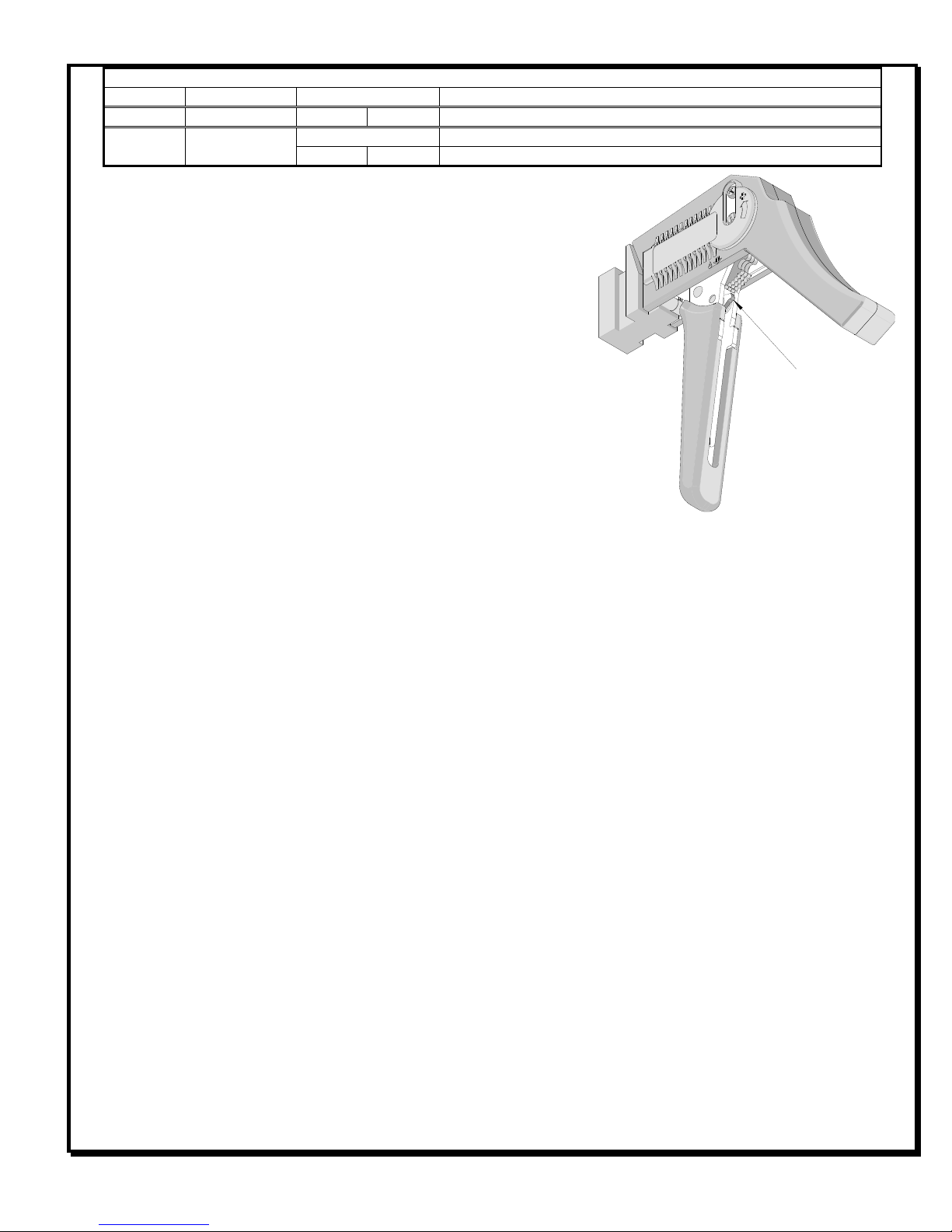
RATCHET
RELEASE LEVER
Figure 1
OPERATION
Select the appropriate Change Head and snap it on the front of the
hand tool until it engages, refer to the chart.
Refer to the specific Change Head module’s Specification Sheet for
operating instructions.
Maintenance
It is recommended that each operator of the tool be made aware of,
and responsible for, the following maintenance steps:
1. Remove the plastic handles from the metal tool frame by removing
the screws and remove dust, moisture, and other contaminants
with a clean brush, or soft, lint free cloth.
2. Do not use any abrasive materials that could damage the tool.
3. Make certain all pins; pivot points and bearing surfaces are protected with a thin coat of high quality machine
oil. Do not oil excessively. The tool was engineered for durability but like any equipment it needs cleaning and
lubrication for a maximum service life of trouble free crimping. Light oil used at the pivot points every 5,000
crimps or 3 months, will significantly enhance the tool life.
4. Wipe excess oil from hand tool, particularly from crimping area.
Miscrimps or Jams
Should this tool ever become stuck or jammed in a partially closed position, Do Not force the handles open or
closed. The tool will open easily by pressing the ratchet release lever up. See Figure 1.
How to Adjust Tool Preload
It may be necessary over the life of the tool to adjust tool handle preload force. Listed below are the steps
required to adjust the crimping force of the hand tool to obtain proper crimp conditions:
1. Remove the 2mm locking screw from the numbered adjusting wheel using a screw driver. See Figure 2.
2. Using the same screw driver turn the adjustment wheel to the next highest number.
Note: The odd numbers are in clockwise (CW) direction and the even numbers are counter clockwise (CCW).
3. Example: If the preload is set at number 5, then to increase the preload, turn the adjustment wheel until the 6
position is located over the 2mm locking screw tapped hole. If it is necessary to move to the 7th position, then
the adjustment wheel should be turned clockwise (CW) until the 7th position is over the 2mm locking screw
tapped hole.
4. Replace the 2mm locking screw, aligning the nearest notch in the setting wheel to locking screw.
5. Check the crimp specifications after the tool handle preload force is adjusted. Repeat these steps until the
desired result is obtained.
th
Doc No: ATS-636000478 Release Date: 12-22-05 UNCONTROLLED COPY Page 2 of 4
Revision: C Revision Date: 07-27-15
Page 3

IDT Manual Hand Tool
NUMBERED ADJUSTMENT
WHEEL
Figure 2
TURN CLOCKWISE (CW) OR
COUNTER CLOCKWISE (CCW)
TO ADJUST THE PRE-LOAD
TURN WITH A SMALL
SCREW DRIVER
REMOVE THE 2MM LOCKING SCREW
Warranty
This tool is for electrical
crimping purposes only. This
tool is made of the best quality
materials. All vital
components are long life
tested. All tools are warranted
to be free of manufacturing
defects for a period of 30
days. Should such a defect
occur, we will repair or
exchange the tool free of
charge. This repair or
exchange will not be
applicable to altered, misused,
or damaged tools. This tool is
designed for hand use only.
Any clamping, fixturing, or use
of handle extensions voids this warranty.
CAUTION: Molex crimp specifications are valid only when used with Molex connectors and tooling.
CAUTIONS:
1. Manually powered hand tools are intended for low volume, prototyping, or field repair. This tool is NOT
intended for production use. Repetitive use of this tool should be avoided.
2. Insulated rubber handles are not protection against electrical shock.
3. Wear eye protection at all times.
4. Use only the Molex connectors specified for crimping with this tool.
Doc No: ATS-636000478 Release Date: 12-22-05 UNCONTROLLED COPY Page 3 of 4
Revision: C Revision Date: 07-27-15
Page 4

IDT Manual Hand Tool
1
Figure 3
2
3
Item Number
Order Number
Description
Quantity
63600-0478
Hand Crimp Tool
Figure 3
1
11-11-0320
Spring (Ratchet)
1 2 63600-0479
Spring (Main)
1 3 69008-0972
Adjuster Wheel
1
PARTS LIST
Visit our Web site at http://www.molex.com
Doc No: ATS-636000478 Release Date: 12-22-05 UNCONTROLLED COPY Page 4 of 4
Revision: C Revision Date: 07-27-15
 Loading...