

Page 1
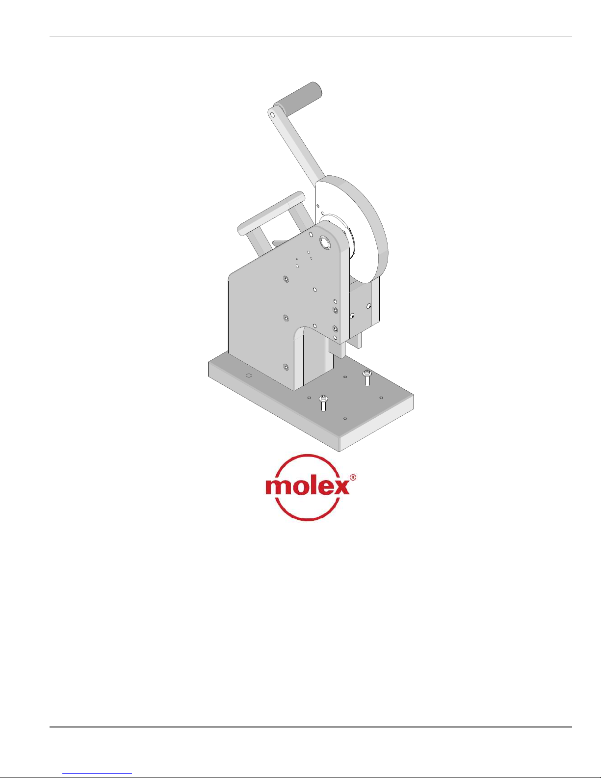
Molex Standard Manual Assembly Press
Molex Standard Manual Assembly Press
Description
Operation
Maintenance
Order No: TM-011316356 Release Date: 02-05-99 UNCONTROLLED COPY Page 1 of 16
Revision: D Revision Date: 10-08-09
Instruction Manual
Order No. 11-31-6356
Engineering No. AM-60026-50
Page 2

Molex Standard Manual Assembly Press
WARNING
NEVER OPERATE, SERVICE, OR ADJUST THIS PRESS OR INSTALL CRIMP DIES WITHOUT PROPER
INSTRUCTION AND WITHOUT FIRST READING AND UNDERSTANDING THE INSTRUCTIONS IN
THIS MANUAL.
WORK SAFELY AT ALL TIMES
For Service, Contact Your
Local Molex Sales Office
Molex Application Tooling Group
2200 Wellington Court
Lisle, Illinois 60532
Tel: 630-969-4550
Fax: 630-505-0049
Order No: TM-011316356 Release Date: 02-05-99 UNCONTROLLED COPY Page 2 of 16
Revision: D Revision Date: 10-08-09
Page 3

Molex Standard Manual Assembly Press
1 General Description
2 Installation, Setup, and Operation
3 Maintenance and Troubleshooting
4 Parts List and Assembly Drawings
Table of Contents
SECTION
Order No: TM-011316356 Release Date: 02-05-99 UNCONTROLLED COPY Page 3 of 16
Revision: D Revision Date: 10-08-09
Page 4

Molex Standard Manual Assembly Press
1.1. Description
1.2. Features
1.3. Technical Specifications
1.4. Delivery Check
1.5. Tools
Section 1
General Description
Order No: TM-011316356 Release Date: 02-05-99 UNCONTROLLED COPY Page 4 of 16
Revision: D Revision Date: 10-08-09
Page 5

Molex Standard Manual Assembly Press
General Description
1.1 Description
The Molex Standard Manual Assembly Press (1131-6356) is versatile, reliable, and inexpensive to
operate. It is designed to provide an effective
method of apply force to a wide variety of
terminating and crimping dies. The Press is easily
converted from right to left hand operation. When
the combinations of crimping dies have been
installed the operator pulls the handle down and
then returns it to the original position. A ratchet
mechanism insures that the press goes through a
full cycle for a complete termination. The press is
suited for low to mid-volume production
requirements.
1.2 Features
Press and tooling is easily portable.
Accepts a wide variety of terminating and
crimping tools kits.
Full cycle ratchet assures complete termination
Easily setup for left or right hand operation.
Tooling changeover is simple and quick.
Termination height is easily adjusted in the
upper tooling holder.
Manually operated, no shop air or electricity
required.
Low handle force to reduce operator fatigue.
1.3 Technical Specifications
Dimensions Press with tooling
Height 533mm (21.00”)
Width 152mm (6.00“)
Depth 267mm (10.50“)
Unpacked weight 23.2kg (50.5 lbs)
Production Rate
300 cycles per hour maximum, depending on
operator skill and tool kit installed.
Operating Parameters
Maximum Force 13.3kN (3,000lbs)
Shut Height 42.0mm (1.65”)
Stroke Length 43.0mm (1.69”)
Adjustment 5.26mm (.207”)
1.4 Delivery Check
The following items are included in this package :
Decription: Quantity
Molex Standard Assembly Press
11-31-6356 (AM-60026-50) 1
Instruction Manual TM-011316356 1
1.5 Tools
The following tools are recommended for setup and
adjustments to the this tool.
Adjustable wrench
Needle nose pliers
English hex wrench set for some non-metric tools.
Order No: TM-011316356 Release Date: 02-05-99 UNCONTROLLED COPY Page 5 of 16
Revision: D Revision Date: 10-08-09
Page 6

Molex Standard Manual Assembly Press
2.1. Instaltion
2.2. Set-Up
2.3. Operation
Section 2
Installation
Order No: TM-011316356 Release Date: 02-05-99 UNCONTROLLED COPY Page 6 of 16
Revision: D Revision Date: 10-08-09
Page 7

Molex Standard Manual Assembly Press
Figure 2
-1
RAM
BASE PLATE
FRAME
RATCHET
RATCHET
FRAME
REMOVE THE
Figure 2
-2
RAM HANDLE
RAM CAM
RAM CAM
RAM HANDLE
REPLACE THE
RIGHT HAND
ROTATE HANDLE
LEFT HAND
RAM HANDLE
HANDLE
RAM CAM
RELEASE
LEVER
2.1 Installation
The Molex Standard Assembly Press 11-31-6356
(AM-60026-50) will need to be secured to a work
surface.
To secure the press, use a bench capable of
supporting at least 150 pounds, with adequate
lighting for easy operation. There are two (2) holes
for 5/16” screws provided in the press base for
fastening the press to the workbench.
2.2 Set Up
Left of Right Handed Operation
The Molex Standard Manual Press can be set
up for either left or right handed operators by
simply reversing the handle on the press lever
by following these steps:
1. Remove the #1/4-20 X 1.0” Long SHCS at the
base of the Ram Handle.
2. Remove the Ram Handle Assembly and rotate it
1800.
3. Replace the Ram Handle Assembly to the Ram
Cam.
4. Replace the #1/4-20 X 1.0” Long SHCS and
tighten securely.
ASSEMBLY
#1/4-20 X1.0LG
SHCS
OPERATION
ASSEMBLY 180O
ASSEMBLY
#1/4-20 X1.0LG
SHCS
OPERATION
Ram Stroke Adjustment
The Ram Stroke Adjustment is made only when
there is a tool kit installed.
1. Place the proper tooling into the press.
2. Loosen the #8-32 set screw in the Ram which
locks the Ram Adjusting Screw into place. See
Figure 2-3.
Order No: TM-011316356 Release Date: 02-05-99 UNCONTROLLED COPY Page 7 of 16
Revision: D Revision Date: 10-08-09
Page 8

Molex Standard Manual Assembly Press
RAM
Figure 2
-5
RATCHET
#8-32 SET
Figure 2
-3
RAM
UP
.207” (
5.26mm)
RAM
RAISE FOR UP
Figure 2
-4
RAM
LOWER FOR
RAM ADJUSTING
ADJUSTING
SCREW
SCREW
POSITION
MINIMUM
DEPTH
MAXIMUM
DEPTH
IN THE DOWN
POSITION
3. There is an indicator engraved on the ram just
above the Ram Adjusting Screw. Turn the Ram
Adjusting Screw clockwise (CW) toward the “+”
sign to increase the ram stroke. To decrease
the stroke, turn the Ram Adjusting Screw
counterclockwise (CCW) toward the “-” sign.
Stroke adjustment controls the shut height of the
connector assembly. See Figure 2-4.
DOWN
POSITION
4. Once the correct stroke is set, tighten the
locking #8-32 set screw.
All tool kits are different and may need additional
adjustments. Refer to the individual Instruction
Manuals for the proper tool kit.
POSITION
2.3 Operation
Ram
To cycle the press, pull the press ram handle
down and then return it to its original position.
Warning: Once the press ram handle has started to
descend, it cannot be returned to the up position
until the full stroke of the press has been
completed. In case of a jam or some other
problem, should the press ram ever need to be
returned to the up position before completing the
full stroke, pull up on the ratchet release lever, and
raise the press ram handle. The ratchet release
lever is located on the upper left side of the press
frame. See Figure 2-5.
HANDLE
RELEASE
LEVER
Order No: TM-011316356 Release Date: 02-05-99 UNCONTROLLED COPY Page 8 of 16
Revision: D Revision Date: 10-08-09
Page 9

Molex Standard Manual Assembly Press
3.1. Cleaning
3.2. Lubrication
3.3. Perishable Parts
3.4. Spare Parts
3.5. Troubleshooting
Section 3
Maintenance
Order No TM-011316356 Release Date: 02-05-99 UNCONTROLLED COPY Page 9 of 16
Revision: D Revision Date: 10-08-09
Page 10

Molex Standard Manual Assembly Press
GREASE
OIL
Figure 3
-1
OIL
OIL ROLLERS and
OIL
ROLLERS and
3.1 Cleaning
For efficient operation, the tooling should be cleaned daily. Use a soft bristle brush to remove debris from critical
areas. For best results, remove the tooling dies from the press. Brush and then use a clean cloth to wipe off the
upper and lower tooling mounting areas. Before reinstalling tooling, wipe all sides of the forms with a clean cloth.
See Chart 3.1 for recommended Preventive Maintenance Schedule.
NOTE: Using compressed air to clean tooling is not recommended. Chips can wedge in the tooling and/or fly at an
operator.
3.2. Lubrication
1. Grease the ram including the up and down stroke feed arm.
2. Oil all moving parts of the press.
3. Lubricate with multipurpose synthetic lubricant with Teflon or an equivalent. Molex ships its presses pre-greased
with Permatex multi-purpose synthetic grease with Teflon No. 82329. A SAE 10 non-detergent oil or light spindle
oil or 3-in-1 oil should be used on pivot points.
WARNING: Never use penetrants such as WD40 for any lubrication on the press.
4. Lubricate all points shown in Figures 3-1 with the specified oil and grease (or equivalent).
GREASE
BEARINGS (2)
BEARINGS (2)
Order No: TM-011316356 Release Date: 02-05-99 UNCONTROLLED COPY Page 10 of 16
Revision: D Revision Date: 10-08-09
Page 11

Molex Standard Manual Assembly Press
An example of a maintenance chart is shown below. Copy and use this chart to track the maintenance of your
Press or use this as a template to create your own schedule or use your company’s standard chart, if applicable.
Preventive Maintenance Chart
Daily: Clean. See Section 3.1.
As Required: Lubricate. See Section 3.2.
CHECK SHEET MONTH _________YEAR _________
Week Daily Clean
1
2
3
4
Cleaning
Lubricate
Inspect all tooling
for wear
MON TUE WED THU FRI SAT SUN
Yes Soft Brush Industrial
Yes Replace if signs of wear.
Days of the Week
Solution
Schedule should be adjusted up or down depending on usage. Molex recommends that a log of preventive
maintenance be kept with the press.
3.3. Perishable Parts
Perishable parts are those parts that come in contact with the product and will wear out over time. Customers are
responsible for maintaining these parts.
There are no perishable parts for Molex Standard Manual Assembly Press. The various tooling kits will have
perishable parts. Molex recommends that all customers keep at least one set of the perishable tool kit in stock at
all times. This will reduce the amount of production down time. For the proper perishable tool kit information,
refer to the Individual Instruction Manual supplied with the Tooling Kits.
3.4. Spare Parts
Customers are responsible for maintaining the Molex Standard Manual Assembly Press. Spare parts are moving
and functioning parts that can be damaged or wear out over time and will require replacement. Molex
recommends that the customer keep some or all of them in stock to reduce production down time. These parts
are identified in the parts list in Section 4.
Order No: TM-011316356 Release Date: 02-05-99 UNCONTROLLED COPY Page 11 of 16
Revision: D Revision Date: 10-08-09
Page 12

Molex Standard Manual Assembly Press
3.5. Troubleshooting
Symptom Cause Solution
Wire does not terminate
properly in terminal
Ram goes down but
will not go up.
Full stroke ratchet
mechanism
not engaging
Improper gauge wire See product for wire gauge
Termination punch set to high or to deep
Sticking ratchet pawl or debris
in mechanism
Adjust the ram stroke. See Ram Stroke
Adjustment See Set-Up. Section 2.2
Clean and lubricate pivot points.
See Section 3 Maintenance.
Release the ram with the ratchet release
Ram set too low
lever and re-adjust the ram stroke.
See Ram Stroke Adjustment See Set-Up.
Section 2.2
Sticking ratchet pawl or debris
in mechanism
Clean and lubricate pivot points.
See Section 3 Maintenance
Broken or damaged ratchet pawl or spring Repair and replace.
Worn Anti-Backup Sprocket Replace.
Order No: TM-011316356 Release Date: 02-05-99 UNCONTROLLED COPY Page 12 of 16
Revision: D Revision Date: 10-08-09
Page 13

Molex Standard Manual Assembly Press
4.1 Parts List
4.2 Assembly Drawings
Section 4
Order No: TM-011316356 Release Date: 02-05-99 UNCONTROLLED COPY Page 13 of 16
Revision: D Revision Date: 10-08-09
Page 14

Molex Standard Manual Assembly Press
4.1 Parts List
Molex Standard Manual Assembly Press 11-31-6356 (AM-60026-50)
Item No. Order No. Engineering No. Description Quantity
1 11-31-7100 AM-60026-1 Base 1
2 11-31-7101 AM-60026-2 Frame Right Hand 1
3 11-31-7102 AM-60026-3 Frame Left Hand 1
4 11-31-7103 AM-60026-4 Tension Column 1
5 11-31-7104 AM-60026-5 Frame Spacer 1
6 11-31-7105 AM-60026-6 Ram 1
7 11-31-7106 AM-60026-7 Ram Adjustment Screw 1
8 11-31-7107 AM-60026-8 Ram Guide Plate 2
9 11-31-7110 AM-60026-11 Ram Cam 1
10 11-31-7111 AM-60026-12 Ram Cam Shaft 1
11 11-31-7113 AM-60026-14 Cam Follower Nut 1
12 11-31-7114 AM-60026-15 Anti-Backup Sprocket 1
13 11-31-7115 AM-60026-16 Anti Backup Pawl 1
14 11-31-7117 AM-60026-18 Anti-Backup Release 1
15 11-31-7118 AM-60026-19 Anti-Backup Release Pivot 1
16 11-31-7119 AM-60026-20 Frame Handle 1
17 11-31-7120 AM-60026-21 Handle Support 2
18 11-31-7121 AM-60026-22 Ram Arm 1
19 11-31-7122 AM-60026-23 Ram Arm Handle 1
20 11-31-7123 AM-60026-24 Handle Shaft 1
21 11-31-7124 AM-60026-25 Front Cover 1
22 11-31-7125 AM-60026-26 Compression Spring .240” OD 2
23 11-31-7126 AM-60026-27 Washer 7/32” ID 2
24 11-31-7128 AM-60026-29 Spacer 2
25 11-31-7132 AM-60026-33 Flat Washer .260” ID 8
26 11-31-7133 AM-60026-34 Flat Washer .340” ID 2
27 11-31-7134 AM-60026-35 Ram Cam Hub 1
28 11-31-7135 AM-60026-36 Spring Anchor 2
29 11-31-7313 AM-60026-37 Hub Spacer 1
30 11-32-4494 AM-60026-98 #8-32 Socket Head Set Screw 1
31 11-32-5278 AM-60026-38 E-Ring .168 ID 1
32 11-32-5279 AM-60026-39 E-Ring .281 ID 1
33 11-32-5280 AM-60026-40 E- Ring .238 ID 8
34 11-31-7108 AM-60026-9 Roller 8
35 11-31-7109 AM-60026-10 Bearing 1/4” ID 8
36 11-31-7112 AM-60026-13 Cam Follower 1
37 11-31-7116 AM-60026-17 Extension Spring .187” OD 1
38 11-31-7127 AM-60026-28 Bearing 5/8” ID 2
39 11-31-7131 AM-60026-32 Detent 1
40 N/A N/A #8-32 by 3/8” Long FHCS 4**
41 N/A N/A #8-32 by 1/4” Long BHCS 2**
42 N/A N/A #8-32 by 3/4” Long SHCS 2**
43 N/A N/A #10-32 by 1/4” Long SSS 1**
44 N/A N/A #1/4-20 by 1.0” Long SHCS 16**
45 N/A N/A #1/4-28 by 3/8” Long SSS Half Dog 2**
46 N/A N/A #5/16-18 by 1-1/2” Long SHCS 6**
47 N/A N/A 1/8 by 5/8” Long Dowel Pin 1**
48 N/A N/A 3/16 by 3/4” Long Dowel Pin 3**
Spare Parts
Hardware
Order No: TM-011316356 Release Date: 02-05-99 UNCONTROLLED COPY Page 14 of 16
Revision: D Revision Date: 10-08-09
Page 15

Molex Standard Manual Assembly Press
Molex Standard Manual Assembly Press 11-31-6356 (AM-60026-50)
Item No. Order No. Engineering No. Description Quantity
49 N/A N/A 5/16 by 1.0” Long Dowel Pin 2**
50 N/A N/A 1/4 by 1-1/2” Long Dowel Pin 8**
** Available from an industrial supply company such as MSC (1-800-645-7270).
Order No: TM-011316356 Release Date: 02-05-99 UNCONTROLLED COPY Page 15 of 16
Revision: D Revision Date: 10-08-09
Page 16

Molex Standard Manual Assembly Press
14
47
24 31
13
37
28
15
48
39
44
16
17
44
25
8
4
33
35
34
50
3
42
23
22
43
44
49
40
1
46
38
10
12
27
9
36
11
30
5
7
29
2
45
32
26
19
20
18
48
44
6
21
41
(4)
(6)
(2)
(2)
(2)
(2)
(2)
(2)
(2)
(2)
(2)
(2)
(2)
(8)
(8)
(8)
(8)
(2)
(2)
(8)
(10
(2)
(2)
4.2 Assembly
Americas Headquarters
Lisle, Illinois 60532 U.S.A.
1-800-78MOLEX
amerinfo@molex.com
Far East North Headquarters
Yamato, Kanagawa, Japan
81-462-65-2324
feninfo@molex.com
Figure 4-1
Far East South Headquarters
Jurong, Singapore
65-6-268-6868
fesinfo@molex.com
Visit our Web site at http://www.molex.com
European Headquarters
Munich, Germany
49-89-413092-0
eurinfo@molex.com
Corporate Headquarters
2222 Wellington Ct.
Lisle, IL 60532 U.S.A.
630-969-4550
Fax: 630-969-1352
Order No: TM-011316356 Release Date: 02-05-99 UNCONTROLLED COPY Page 16 of 16
Revision: D Revision Date: 10-08-09
 Loading...