

Page 1

MolecuLight i:XTM User Manual
Trademarks
MolecuLightTM, MolecuLight i:XTM, MolecuLight DarkDrapeTM, MolecuLight AdapterTM, Standard Imaging ModeTM,
Fluorescence Imaging Mode
TM
, ST-imageTM, ST-videoTM, FL-imageTM, FL-videoTM are trademarks of MolecuLight, Inc.
Patent Information
The MolecuLight i:X Imaging Device (hereafter referred to as the device, MolecuLight i:X or MolecuLight i:X Imaging Device)
contains patented technology developed by MolecuLight Inc.:
Canadian Patent No. 2,724,973
U.S. Patent No. 12/992,040
Global patents and further U.S. patents are pending.
Publication Information
User Manual, Part Number 1294, Revision 1.1
Contact Information
The MolecuLight i:X and its accessories are designed and manufactured by MolecuLight Inc.
MolecuLight Inc.
425 University Ave., Suite 700
Toronto, Ontario, Canada
M5G 1T6
Telephone: +1-647-362-4684, or 1-877-818-4360 (North America Only)
Fax: 647-362-4730
Email: [email protected]
www.moleculight.com
The European authorized representative for MolecuLight Inc. is Emergo.
Emergo Europe
Prinsessegracht 20
2514 AP The Hague
The Netherlands
MolecuLight i:X
TM
User Manual Revision 1.1 Page 2 of 43
Page 2

Contents
1 INTRODUCTION ........................................................................................................................................................................ 5
2 WARNINGS, CAUTIONS, AND NOTES ........................................................................................................................................ 5
2.1 WARNINGS, CAUTIONS, AND NOTES .......................................................................................................................................................... 5
2.1.1 General Warning Messages ........................................................................................................................................................... 5
2.1.2 General Caution Messages ............................................................................................................................................................ 6
2.1.3 Acronym Table .............................................................................................................................................................................. 7
2.2 SYMBOLS .............................................................................................................................................................................................. 7
2.2.1 Symbols Used on the MolecuLight i:X Imaging Device Label ........................................................................................................ 7
2.2.2 Symbols Used on MolecuLight i:X ................................................................................................................................................. 8
2.2.3 Symbols Used on MolecuLight i:X Packaging ................................................................................................................................ 8
2.2.4 Symbols Used for MolecuLight DarkDrape Label .......................................................................................................................... 9
2.2.5 Symbols Used for MolecuLight DarkDrape Package Label ............................................................................................................ 9
2.3 CERTIFICATIONS ..................................................................................................................................................................................... 9
2.3.1 Classifications .............................................................................................................................................................................. 10
2.4 ELECTROMAGNETIC COMPATIBILITY ......................................................................................................................................................... 10
2.5 INFORMATION ON LASER RADIATION OUTPUT ............................................................................................................................................ 10
3 CONTENTS .............................................................................................................................................................................. 11
3.1 MOLECULIGHT I:X SYSTEM CONTENTS ..................................................................................................................................................... 11
3.2 MOLECULIGHT I:X ACCESSORIES AND CONSUMABLES .................................................................................................................................. 11
4 MOLECULIGHT I:X IMAGING DEVICE OV ERVIEW ..................................................................................................................... 12
4.1 MOLECULIGHT I:X IMAGING DEVICE DESCRIPTION AND USE ......................................................................................................................... 12
4.2 HOW MOLECULIGHT I:X CREATES IMAGES IN FL-MODE .............................................................................................................................. 14
4.3 MOLECULIGHT DARKDRAPE AND MOLECULIGHT ADAPTER DEVICE DESCRIPTION AND USE ................................................................................. 15
5 INTENDED USE AND INDICATION FOR USE ............................................................................................................................. 15
5.1 OFF LABEL USE .................................................................................................................................................................................... 15
6 DEVICE BASICS ........................................................................................................................................................................ 15
6.1 POWER BUTTON .................................................................................................................................................................................. 16
6.1.1 Status Indicator LEDs ................................................................................................................................................................... 17
6.1.1.1 System Status LED .......................................................................................................................................................................... 17
6.1.1.2 Range Finder LED ........................................................................................................................................................................... 17
6.1.1.3 Ambient Light Status LED ............................................................................................................................................................... 18
6.1.1.4 Battery Status LED .......................................................................................................................................................................... 19
6.1.2 Rocker Switch .............................................................................................................................................................................. 19
7 QUICK START GUIDE ............................................................................................................................................................... 19
8 ENVIRONMENTAL CONDITIONS THAT AFFEC T USE ................................................................................................................. 20
8.1 LIGHTING ............................................................................................................................................................................................ 20
8.2 OPERATING TEMPERATURE .................................................................................................................................................................... 20
8.3 STORAGE ............................................................................................................................................................................................ 20
9 OPERATING INSTRUCTIONS .................................................................................................................................................... 20
9.1 PROPER IMAGING TECHNIQUE ................................................................................................................................................................ 20
9.2 HANDLING MOLECULIGHT I:X ................................................................................................................................................................. 21
9.3 IMAGING WITH MOLECULIGHT I:X (IX CAMERA APP) .................................................................................................................................. 22
9.3.1 Capture an Image ........................................................................................................................................................................ 22
9.3.1.1 Capture an ST-image ...................................................................................................................................................................... 22
9.3.1.2 Capture an FL-image ...................................................................................................................................................................... 23
9.3.1.3 Capture a video .............................................................................................................................................................................. 23
9.3.1.4 Capture an ST-video ....................................................................................................................................................................... 23
9.3.1.5 Capture an FL-video ....................................................................................................................................................................... 24
9.4 REVIEW IMAGES AND/OR VIDEOS USING THE IMAGE LIBRARY ....................................................................................................................... 25
TM
MolecuLight i:X
User Manual Revision 1.1 Page 3 of 43
9.5 USING THE ALBUM FEATURE (OPTIONAL) ................................................................................................................................................. 25
9.5.1 Creating a New Album................................................................................................................................................................. 26
9.5.2 Accessing and Using Previously Created Albums ........................................................................................................................ 27
9.5.3 Capture Image and Video Capture Screens ................................................................................................................................. 28
9.5.3.1 Capture Screens when the Active Album is the Camera Roll ......................................................................................................... 28
9.5.3.2 Capture Screens when the Active Album is Created ...................................................................................................................... 28
9.5.4 Deleting Albums .......................................................................................................................................................................... 28
9.6 ZOOMING IN AND OUT AND PANNING ...................................................................................................................................................... 29
9.6.1 Zooming in and out ..................................................................................................................................................................... 29
9.6.2 Panning ........................................................................................................................................................................................ 29
9.7 DELETING IMAGES AND VIDEOS ............................................................................................................................................................... 29
9.8 CHARGING MOLECULIGHT I:X ................................................................................................................................................................. 29
9.8.1 Charge the MolecuLight i:X Imaging Device ................................................................................................................................ 30
9.8.2 Charge the MolecuLight i:X Display Screen ................................................................................................................................. 30
9.9 UPLOADING IMAGES AND VIDEOS TO COMPUTER ....................................................................................................................................... 30
9.10 DISPLAY SCREEN FUNCTIONALITY ............................................................................................................................................................. 31
9.10.1 Basic Display Screen Functionality for MolecuLight i:X Use .................................................................................................... 31
9.10.1.1 Home Button ................................................................................................................... ............................................................... 31
9.10.2 Connect to a Wi-Fi Network .................................................................................................... ................................................ 32
9.10.3 Connect to the Internet .......................................................................................................................................................... 32
9.10.4 Create a Passcode ................................................................................................................................................................... 32
10 MEASURING WOUND AREA ................................................................................................................................................... 33
10.1 SETTINGS MENU .................................................................................................................................................................................. 33
10.1.1 Wound Border Thickness ........................................................................................................................................................ 33
10.1.2 Display of Length & Width Dimensions ................................................................................................................................... 33
10.1.2.1 Length & Width .............................................................................................................................................................................. 34
10.1.2.2 Vertical & Horizontal ......................................................................................................... ............................................................. 34
10.2 AUTO MODE ....................................................................................................................................................................................... 34
10.3 MANUAL MODE ................................................................................................................................................................................... 35
10.3 SAVING A WOUND MEASUREMENT ......................................................................................................................................................... 35
11 INTERPR ETATION OF FLUORESCENCE IMAGES ....................................................................................................................... 35
11.1 COLOR BLINDNESS ................................................................................................................................................................................ 36
12 CLEANING AND DISINFECTING MOLECULIGHT I:X ................................................................................................................... 37
12.1 PRE-CLEAN THE MOLECULIGHT I:X .......................................................................................................................................................... 37
12.2 DISINFECT THE MOLECULIGHT I:X ............................................................................................................................................................ 37
12.3 CLEAN THE MOLECULIGHT I:X................................................................................................................................................................. 37
12.4 PRE-CLEAN THE MOLECULIGHT ADAPTER .............................................................................................................................. ................... 38
12.5 DISINFECT THE MOLECULIGHT ADAPTER ................................................................................................................................................... 38
13 MAINTENANCE OF MOLECULIGHT I:X ..................................................................................................................................... 38
14 DISPOSAL OF MOLECULIGHT I:X ............................................................................................................................................. 38
15 TROUBL ESHOOTING AND SUPPORT ....................................................................................................................................... 38
15.1 FREQUENTLY ASKED QUESTIONS ............................................................................................................................................................. 38
15.2 IX CAMERA APP TROUBLESHOOTING ........................................................................................................................................................ 41
16 WARRAN TY ............................................................................................................................................................................ 42
APPENDIX A: SPECIFICATIONS ............................................................................................................................................................ 43
APPENDIX B: MOLECULIGHT I:X IMAGING DEVICE OVERVIEW
APPENDIX C: MOLECULIGHT I:X IMAGING DEVICE QUICK START GUIDE
APPENDIX D: MOLECULIGHT DARKDRAPE AND ADAPTER INSTRUCTIONS FOR USE
APPENDIX E: MOLECULIGHT I:X WOUND MEASUR EMENT QUICK START GUIDE
TM
MolecuLight i:X
User Manual Revision 1.1 Page 4 of 43
Page 3
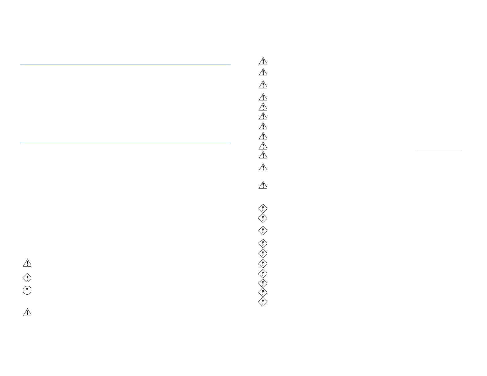
Warning
Messages with this heading indicate serious adverse reactions, potential safety hazards, and
limitations in use imposed by a condition labeled with a warning. The warning identifi
es steps that
should be taken if the incident occurs.
Caution
Messages with this heading indicate information regarding any special care to be exercised by the user
and/or patient for the safe and effective use of the device. All caution statements should be followed
to ensure data and device integrity.
Messages with this heading provide additional information that increase the user’s understanding of
the operation of the device.
Warning
The use of an accessory or cable with the MolecuLight i:X Imaging Device other than those specified in
Section
3 may result in increased emissions or decreased immunity of the MolecuLight i:X Imaging
Device.
Warning
The MolecuLight i:X Imaging Device comes fully assembled and ready for use. No modification of this
equipment is allowed. Modification of the device will void the terms of the warranty.
Warning
Do not stack the
MolecuLight i:X Imaging Device.
Warning
MolecuLight i:X is intended to be used in a hospital/clinic by trained health care professionals. Avoid
exposure to magnetic fields, electrostatic discharge and thermal ignition sources
during use of the
device.
Warning
Do not charge or use the device in areas with potentially explosive atmospheres such as fueling areas
or in areas where the air contains chemicals or particles.
Warning
Do not point the violet wavelength LEDs directly into eyes (see
Figure 2, item 12).
Warning
MolecuLight i:X is not suitable for use in the presence of flammable anesthetic mixtures with air,
oxygen or nitrous oxide.
Warning
Protect MolecuLight i:X against dust and moisture by storing it in its original shipping package
overnight or when not in use for prolonged periods of time.
Warning
Avoid strong physical shocks and dropping.
Warning
Any damage to the device (crack or other visible deformity) may affect the functional, intended use
and/or safety of the MolecuLight i:X. Contact MolecuLight for guidance at [email protected].
Warning
Do not soak or immerse MolecuLight i:X in water or other liquids.
Warning
Be aware of surroundings when operating MolecuLight i:X in a dark environment. The environment
should be safe to prevent tripping or bumping into any objects
during fluorescence imaging
procedures.
Warning
Portable RF communications equipment (including peripherals such as antenna cables and external
a
ntennas) should be used no closer than 30 cm (12 inches) to any part of the MolecuLight i:X,
including cables that may be specified by MolecuLight Inc. Otherwise, degradation of the performance
of MolecuLight i:X could result.
Caution
Do not attempt to use the device while it is charging. The device will not function.
Caution
Keep the Illumination Zone clean and avoid covering the Violet Wavelength LEDs and camera sensor
window with your fingers, as this may affect illumination and image quality (see Figure 2, item 15).
Caution
Prior to charging the device, ensure the MolecuLight Power Cable P/N 1142 (described in Section 3.1)
is
undamaged before plugging into a wall outlet. Use of an extension cord or an electrical power bar is
discouraged.
Caution
When charging is complete, the MolecuLight Power Cable P/N 1142 should initially be disconnected
from the wall electrical outlet and then removed from the MolecuLight i:X Imaging Device.
Caution
Use of controls, adjustments or procedures other than those specified in this User Manual may result
in hazardous laser light radiation exposure from the Range Finder Sensor (Section 2.5).
Caution
The MolecuLight i:X Imaging Device is restricted to use by trained health care professionals and should
be protected from unauthorized use.
Caution
The Heat Sink (Figure 2, item 7) may get warm after prolonged use. The device will shut down if
temperature exceeds 46
0
C or 1150F.
Caution
Improper cleaning/disinfection
of the device may result in distorted images.
Caution
Images/videos should be regularly downloaded and saved to avoid loss of patient information.
Caution
Non-MolecuLight Apps may appear on the MolecuLight i:X for download. Do not download any nonMolecuLight Apps in order to maintain the device configuration intended for use.
1 Introduction
Congratulations on your purchase of the MolecuLight i:X
allows you to rapidly visualize potentially harmful bacteria in real-time during wound assessment and includes a wound
measurement application for quick wound area measurements. MolecuLight is confident that as you use the MolecuLight
i:X Imaging Device you will find new and helpful information about the bacterial load in and around wounds during the
clinical examination process, helping you to better manage wound treatment for your patients.
The device is designed to aid and simplify clinical assessment, microbial sampling and treatment of wounds provided by
clinicians at the point-of-care. Its compact, handheld size and intuitive and simple user interface are designed for use across
hospitals and wound care clinical settings.
MolecuLight Inc. provides technical support, a User Manual, a Quick Start Guide and other educational references to aid you
with the use of the MolecuLight i:X Imaging Device. Please review this User Manual thoroughly before operating your
device.
TM
Imaging Device. The handheld MolecuLight i:X Imaging Device
2 Warnings, Cautions, and Notes
Please read the following safety information before using the MolecuLight i:X Imaging Dev ice.
The MolecuLight i:X is an imaging device that does not require contact with the patient. It captures images/videos and
utilizes safe levels of violet wavelength light to illuminate a wound for fluorescence imaging. The MolecuLight i:X Imaging
Device does not require the use of exogenous imaging contrast agents.
The MolecuLight i:X is a Class II medical device per Health Canada Regulations.
The MolecuLight i:X is a Class IIa medical device per MDD 93/42/EEC.
MolecuLight i:X is intended for use by trained health care professionals.
There are no known contraindications or side effects associated with the use of the MolecuLight i:X.
Some patients may experience some warmth from the device during exposure.
The Range Finder Sensor (see Figure 2, item 14) contains a fully-enclosed laser. No hazardous laser radiation is emitted
during use.
No eye or skin protection is required for the user or patient when operating the MolecuLight i:X.
Refer to Section 2.1.3 for the meaning of acronyms used throughout this User Manual.
2.1 Warnings, Cautions, and Notes
Warnings, cautions, and notes are used to describe serious and non-serious safety conditions of the device. The symbols
used to describe these safety conditions are:
2.1.2 General Caution Messages
Note
2.1.1 General Warning Messages
TM
MolecuLight i:X
User Manual Revision 1.1 Page 5 of 43
TM
MolecuLight i:X
User Manual Revision 1.1 Page 6 of 43
Page 4
Acronym
Meaning
RF
Radio Frequency
ST-imageTM
An image captured in Standard Imaging Mode
ST-videoTM
A video captured in Standard Imaging Mode
FL-imageTM
An image captured in Fluorescence Imaging Mode
FL-videoTM
A video captured in Fluorescence Imaging Mode
LED
Light Emitting Diode
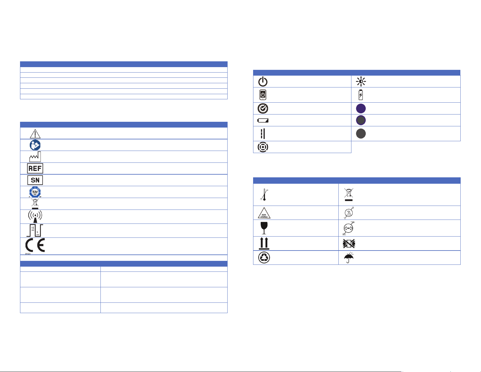
Symbol
Meaning
Dispose of the MolecuLight i:X in accordance with your country’s legal requirements for the disposal
of electrical and electronic waste
continuously on for 15 minutes in Fluorescence Imaging Mode, violet
CE Marking indicates European Conformity to essential requirements of applicable European
Rx only
For prescription use
Statement
Meaning
CAN ICES-3(B)/NMB-3(B)
Self-Declaration of Compliance (SDoC) to Industry Canada ICES-003(B)
For further information related to this statement, refer to Section 2.3
for specific certification and Section 2.4
for electromagnetic
compatibility
For use only with Power Cable P/N:
N/P: 1142
For further information related to accessories and consumables, refer
Contains FCC ID:BCG-A1421 and IC:579CA1421
In reference to iPod touch (part of the MolecuLight i:X, referred to as
the Display Screen)
Symbol
Source & Meaning
Symbol
Source & Meaning
Source: IEC 60417-5010
Meaning: Power Button
Source: MolecuLight symbol
Meaning: Ambient Light Status
Source
Meaning
Source: MolecuLight symbol
Meaning: Port for Charging Display Screen and
Data Transfer
Source: MolecuLight symbol
Meaning: System Status
Source: MolecuLight symbol
Meaning: Fluorescence Imaging Mode
Source: IEC 60417-5546
Meaning: Battery Status
Source: MolecuLight symbol
Meaning: Standard Imaging Mode
Source: IEC 60417-5031
Meaning
: MolecuLight i:X Charging Port
(D.C)
Source
: MolecuLight symbol
Meaning
: Home Button (for Display Screen)
Source: MolecuLight symbol
Meaning: Range Finder
Symbol
Source & Meaning
Symbol
Source & Meaning
Source: ISO 15223-1:2012
Meaning:
C
to 50
F) ambient
temperature
Source: WEEE symbol, EU Directive 2012/19/EU
Meaning:
accordance with your country’s legal requirements for
the disposal of electrical and electronic waste
Source:
Meaning:
Source:
Meaning:
Source:
Meaning:
Source: ISO 15223-1:2012
Meaning:
atmospheric pressure
Source:
Meaning:
Source:
Meaning:
Source:
Meaning
Source:
Meaning
2.1.3 Acronym Table
2.2 Symbols
2.2.1 Symbols Used on the MolecuLight ii:X Imaging Device Label
The following table lists the symbols and statements used on the MolecuLight i:X Imaging Device label (silver label).
Caution, consult accompanying documents
2.2.2 Symbols Used on MolecuLight ii:X
The following table lists the symbols used in the labeling of MolecuLight i:X.
: MolecuLight symbol
: Display Screen Power Button
Read User Manual
Date of manufacture
Catalog number
Serial number
Certification of safety testing
RF transmitter for wireless transmission
Device duty cycle (if device is
LEDs should be turned off for 5 minutes before Fluorescence Imaging Mode is accessed again)
product directives; 0123 represents MolecuLight Inc.’s Notified Body
The MolecuLight i:X Imaging Device
complies with Part 15 of the FCC Rules
1142. A utiliser uniquement avec Câble
Table 1: Symbols and statements on MolecuLight i:X Imaging Device label
TM
MolecuLight i:X
User Manual Revision 1.1 Page 7 of 43
to Section 3
Table 2: MolecuLight i:X symbols
2.2.3 Symbols Used on MolecuLight i:X Packaging
The following table lists the symbols and statements used on the MolecuLight i:X packaging label and indicates storage and
transportation conditions.
o
o
Dispose of the MolecuLight i:X in
ISO 15223-1:2012
Maintain within 10% to 70% humidity
Maintain within 89 kPa to 102 kPa for
MolecuLight symbol
Do not stack or compress
ISO 15223-1:2012
: Keep dry
MolecuLight i:X
Maintain within -10
o
C (14oF to 122
ISO 15223-1:2012
Non sterile
ISO 15223-1:2012
Fragile
ISO 7000:2014
Face up
ISO 7000:2014
: Recyclable
Table 3: MolecuLight i:X transportation and storage conditions
TM
User Manual Revision 1.1 Page 8 of 43
Page 5
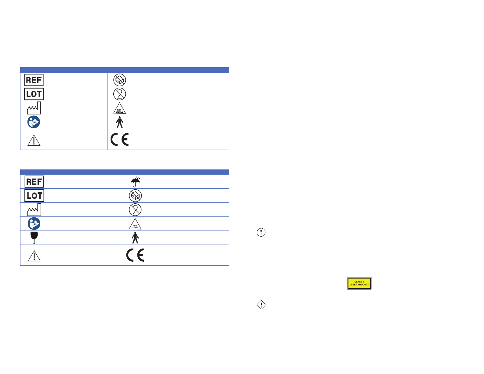
Symbol
Source & Meaning
Symbol
Source & Meaning
Source:
Meaning:
Source:
Meaning:
Source:
Meaning:
Source:
Meaning:
Source:
Meaning:
Source:
Meaning:
Source:
Meaning:
Source:
Meaning:
Source:
Meaning:
Source: European Conformity Marking
Meaning:
product meets the requirements of the applicable EC
directives
Symbol
Source & Meaning
Symbol
Source & Meaning
Source
: ISO 15223-1:2012
Meaning
: Catalog number
Source:
Meaning
Source
: ISO 15223-1:2012
Meaning:
Batch code
Source:
Meaning
Source:
ISO 15223-1:2012
Meaning
: Date of manufacture
Source:
Meaning
Source:
ISO 7010:2011
Meaning
: Read User Manual
Source:
Meaning
Source:
ISO 15223-1:2012
Meaning
: Fragile
Source:
Meaning
Source:
ISO 15223-1:2012
Meaning:
Caution, consult
accompanying documents
Source: European Conformity Marking
Meaning:
the product meets the requirements of the
applicable EC directives
Note
The emissions characteristics of the MolecuLight i:X make it suitable for use in industrial areas and
hospitals (CISPR 11 class A).
MolecuLight i:X is not intended for use in a residential environment
and does
not comply with
IEC 60601-1-11:2015 General requirements for basic safety and essential performance --
Collateral standard: Requirements for medical electrical equipment and medical electrical systems used in
the home healthcare environment.
Caution
Do not point the laser (from the
2.2.4 Symbols Used for MolecuLight DarkDrape Label
The following table lists the symbols and statements used on the MolecuLight DarkDrape label.
ISO 15223-1:2012
Catalog number
ISO 15223-1:2012
Batch code
ISO 15223-1:2012
Date of manufacture
ISO 7010:2011
Read User Manual
ISO 15223-1:2012
Caution, consult
accompanying documents
Table 4: Symbols and statements on the MolecuLight DarkDrape label
ISO 15223-1:2012
Do not use if package is damaged
ISO 15223-1:2012
For single use only
ISO 15223-1:2012
Non sterile
IEC 60417 – 5840
Type B applied part
Manufacturer's declaration that the
2.2.5 Symbols Used for MolecuLight DarkDrape Package Label
The following table lists the symbols and statements used on the MolecuLight DarkDrape packaging label.
ISO 15223-1:2012
: Keep dry
ISO 15223-1:2012
: Do not use if package is damaged
ISO 15223-1:2012
: For single use only
ISO 15223-1:2012
: Non sterile
IEC 60417 – 5840
: Type B applied part
Manufacturer's declaration that
Table 5: Symbols and statements on the MolecuLight DarkDrape package label (10-pack and 50-pack)
2.3 Certifications
The MolecuLight i:X Imaging Device complies with the following standards:
x Safety Testing per IEC 60601-1:2005+A1:2012 / EN 60601-1:2006+A1:2013
including Canadian National Differences per CAN/CSA-C22.2 No. 60601-1:14 and
US National Differences per ANSI/AAMI ES 60601-1:2005/A1:2012
x Safety EMC Testing per IEC 60601-1-2:2014 4th Edition / EN 60601-1-2:2015
x Safety LED testing per IEC 60601-2-57:2011 and IEC 62471:2006 / EN 60601-2-57:2011 and EN 62471:2008
x Usability Testing per IEC 60601-1-6:2010+A1:2013 / EN 60601-1-6:2010 and EN 62366:2008
x Risk Management per ISO 14971:2007 / EN ISO 14971:2012
TM
MolecuLight i:X
User Manual Revision 1.1 Page 9 of 43
x Quality Management System Requirements per ISO 13485:2016 / EN ISO 13485:2016
The MolecuLight DarkDrape complies with ISO 10993-1:2009 / EN ISO 10993-1:2009: Biological evaluation of medical
devices.
2.3.1 Classifications
MolecuLight i:X has an operational duty cycle of 15 minutes on, 5 minutes off. The implication for this duty cycle is that if
the MolecuLight i:X is continuously used in Fluorescence Imaging Mode for 15 minutes, the device will need to be switched
to Standard Imaging Mode for 5 minutes before selecting Fluorescence Imaging Mode again to allow for optimal
performance of the Violet Wavelength LEDs.
The medical device classification of the MolecuLight i:X in Canada is Class II medical device and a Class IIa medical device in
Europe. Alone, the MolecuLight i:X does not require patient contact for use. The MolecuLight DarkDrape (used in
combination with the MolecuLight Adapter and MolecuLight i:X to achieve an optimal lighting environment for imaging
wounds) is a Type B patient applied part which complies with medical device biocompatibility requirements.
The MolecuLight i:X is classified as “IPX0” for fluid ingress, therefore it has no inherent protection against damage from
exposure to liquids.
2.4 Electromagnetic Compatibility
The MolecuLight i:X Imaging Device meets the requirements of Safety EMC Testing per IEC 60601-1-2:2014 4th Edition / EN
60601-1-2:2015. Medical electrical equipment requires special precautions regarding electromagnetic compatibility (EMC)
and must be used according to the instructions in this User Manual.
While unlikely, it is possible that high levels of emitted radio-frequency (RF) electromagnetic interference (EMI) from other
portable and mobile RF communications equipment or nearby radio-frequency sources could result in performance
disruption of the MolecuLight i:X Imaging Device.
To avoid the risk of increased electromagnetic emissions or decreased immunity from such emissions, use only accessories
recommended by MolecuLight (i.e. MolecuLight Power Cable, see Section 3.1). Connection of accessories not recommended
by MolecuLight will void product warranty and could result in malfunctioning of the MolecuLight i:X Imaging Device or other
devices located in the area.
This device complies with Part 15 of the US FCC Rules. This device complies with Canadian ICES-003 (B).
2.5 Information on Laser Radiation Output
The MolecuLight i:X Imaging Device uses a miniature pulsed laser-based range finder to determine the optimal distance
between the device and the wound for superior image quality. The laser module in the range finder emits light at 850 nm
which is invisible to the human eye. The laser’s individual pulse duration is 3.33 ns and the pulse train is 52.3 ms at a 200 ms
repetition rate. The laser complies with 21 CFR 1040.10 and 1040.11 except for deviations pursuant to Laser Notice No.50.
The laser is a Class 1 certified laser
MolecuLight i:X
TM
User Manual Revision 1.1 Page 10 of 43
Range Finder sensor) into eyes (Figure 2, item 14).
Page 6
# in
Figure 1
1
MolecuLight i:X Imaging Device
Device operates on Apple iOS software
MolecuLight Power Cable
Cable to charge the MolecuLight i:X Imaging Device and download
images/videos to a computer; Includes geography
specific plug adaptors (where
applicable)
3
Quick Start Guide
Step by step guide for MolecuLight i:X use
4
User Manual
Provides detailed instructions on use of the MolecuLight i:X
Optical
5 x Optical lens cleaning towelettes, individually packaged for cleaning display
screen and optical windows (ProWorks)
6
MolecuLight WoundStickers
1 box of 2,000 stickers for wound area measurement with the MolecuLight i:X
Note
The MolecuLight DarkDrape and MolecuLight Adapter (Figure 1, items 7-8) are not part of the
MolecuLight i:X System configuration. They are optional accessories that may be ordered separately.
# in
Figure 1
MolecuLight
Part #
Reorder from MolecuLight
MolecuLight
Power Cable
Cable to charge the MolecuLight i:X Imaging
Device
computer; Includes geography
adaptors (where applicable)
3
Quick Start Guide
Step by step guide for MolecuLight i:X use
1295
Yes
User Manual
Provides detailed instructions on use of the
MolecuLight i:X
Optical Lens
Wipes
100)
Box of 100 optical lens cleaning towelettes,
individually packaged for cleaning
screen
and optical windows (ProWorks)
MolecuLight
WoundStickers
1 box of 2,000 stickers for wound area
measurement with the MolecuLight i:X
MolecuLight
Adapter
Reusable Adapter to connect MolecuLight
DarkDrape to the MolecuLight
optimal lighting environment for imaging wounds
MolecuLight
DarkDrape
(Case
of 50)
Case of 50 MolecuLight DarkDrapes, individually
packaged for one
time use to create an optimal
lighting environment for imaging wounds
eo
Lens Cleaning
Solution
Lens cleaning solution t
optical components
No; available from Edmund
Optics, Fisher Scientific,
VWR, Staples.com,
Amazon.com
Fisherbrand Lens
Paper (4’’x
Len paper t
components
No; available from Fisher
Scientific,
Staples.com, Amazon.com
CaviWipes
Disinfecting wipes to clean the device between
uses (Metrex)
No; available from Metrex,
K
Fisher Scientific
Warning
Do not connect the MolecuLight i:X Imaging Device to a power supply using cables that have not
been approved by MolecuLight.
Note Lens Cleaning Solution and Lens Paper may be used instead of the Lens Cleaning
3 Contents
To reorder items available from MolecuLight, contact MolecuLight by email: [email protected].
Item Description
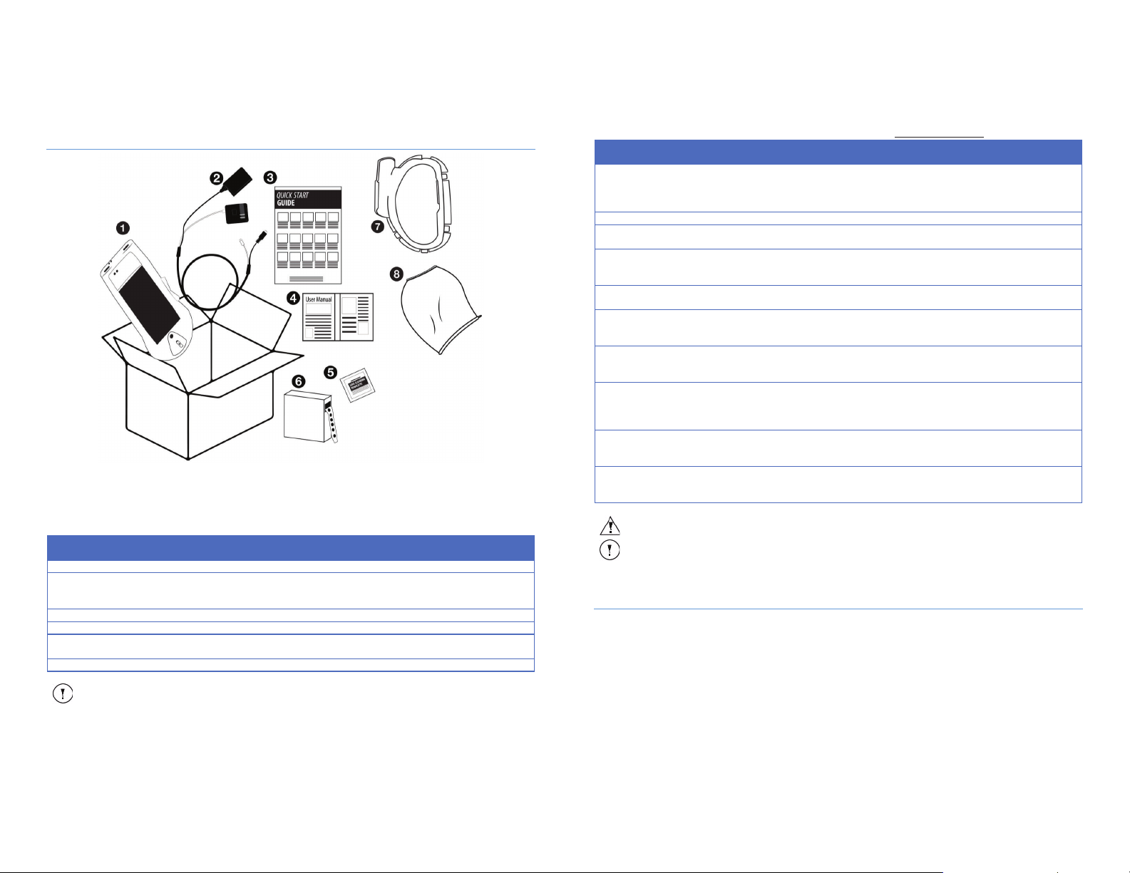
Figure 1: MolecuLight i:X Imaging Device and its components
3.1 MolecuLight ii:X System Contents
The MolecuLight i:X Imaging Device comes fully assembled and ready for use. The standard system configuration includes
items 1-6 illustrated in Figure 1 and detailed in Table 6 below. These items allow the MolecuLight i:X Imaging Device to be
used in a patient care setting.
Item Description
2
5
Lens Wipes
Table 6: List of items included with the MolecuLight i:X System (P/N 1153)
-
3.2 MolecuLight i:X Accessories and Consumables
MolecuLight i:X accessories and consumables are listed below in Table 7 along with suggested vendors from which the
items may be purchased (if not available from MolecuLight).
TM
MolecuLight i:X
User Manual Revision 1.1 Page 11 of 43
2
4
5
6
7
8
N/A
N/A
N/A
Detailed information about cleaning and disinfecting the MolecuLight i:X is provided in Section 12.
(Box of
TECHSPEC
6’’)
and download images/videos to a
-specific plug
display
i:X to create an
-
o clean the device’s
(Edmund Optics)
o clean the device device’s optical
(Fisher Scientific)
Table 7: List of recommended MolecuLight i:X accessories and consumables
1142 Yes
1294 Yes
1182 Yes
1266 Yes
1215 Yes
1212 Yes
N/A
N/A
N/A
VWR,
-Dental, Amazon.com,
Towelette.
4 MolecuLight ii:X Imaging Device Overview
4.1 MolecuLight i:X Imaging Device Description and Use
The MolecuLight i:X Imaging Device allows clinicians to quickly, safely and easily visualize potentially harmful bacterial
presence and distribution on skin and in wounds, in real-time at the point-of-care. The device is non-contact and no imaging
contrast agents are required for fluorescence imaging.
The MolecuLight i:X Imaging Device is a handheld medical device comprised of a high-resolution color LCD display and
touch-sensitive screen with integrated optical and microelectronic components. MolecuLight i:X uses its patented
technology to enable real-time standard light and fluorescence imaging of bacteria and tissue components in wounds and
surrounding healthy skin of patients.
The MolecuLight i:X Imaging Device captures real-time images (JPEG format) and videos (MOV format) in Standard Imaging
TM
and Fluorescence Imaging ModeTM. These modes are identified as follows:
Mode
MolecuLight i:X
TM
User Manual Revision 1.1 Page 12 of 43
Page 7
Note
Wound measurement is
only possible on an ST-Image (see Section 10).
Warning
Heat Sink
Note
Keep the Illumination Zone clean and avoid covering the Violet Wavelength LEDs and camera sensor
window with your fingers
Caution
The MolecuLight i:X Imaging Device is restricted to use by trained health care professionals and
should be protected from unauthorized use.
Caution
Keep the Illumination Zone clean and avoid covering the Violet Wavelength LEDs and camera sensor
window with your fingers, as this may affect illumination and image quality (see Figure 2, item 15).
Note The red color may appear orange to some users
.
1. Standard Imaging Mode
In Standard Imaging Mode, MolecuLight i:X is able to capture the following images:
a. ST-image
b. ST-video
TM
(or ST-Mode): Real-time imaging as per standard photography.
TM
: An image captured in Standard Imaging Mode
TM
: A video captured in Standard Imaging Mode
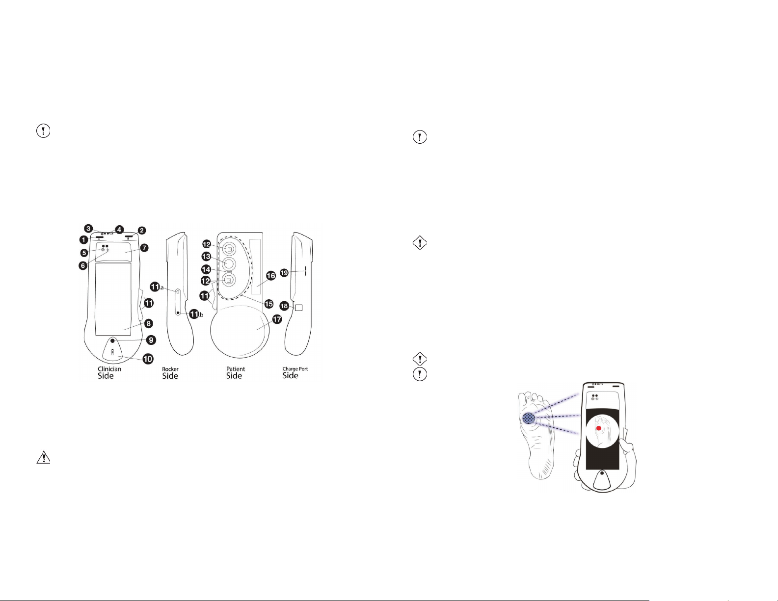
13. Camera Sensor Window: protects the camera sensor which allows image and video capture
14. Range Finder Sensor: detects optimal distance from wound, and
Ambient Light Sensor: detects optimal lighting conditions for Fluorescence Imaging Mode
15. Illumination Zone: area includes camera sensor window, Violet Wavelength LEDs, Ambient Light Sensor and Range
Finder Sensor
2. Fluorescence Imaging ModeTM (or FL-Mode): Real-time imaging in Fluorescence Imaging Mode as a result of violet light
illumination. In Fluorescence Imaging Mode, MolecuLight i:X is able to capture the following images:
a. FL-image
b. FL-video
The device provides image-guidance during visual assessment of wounds.
The device can capture an ST-image
TM
: An image captured in Fluorescence Imaging Mode
TM
: A video captured in Fluorescence Imaging Mode
TM
, ST-videoTM, FL-imageTM, and FL-video
TM
of wounds to quickly identify the presence
and extent of harmful bacteria. This helps to guide the clinical team towards a more comprehensive wound examination
through guided or ‘targeted’ debridement and sampling of potentially harmful bacteria. Images can be appended to a
patient’s clinical care record by exporting the images in JPEG format or printing them (see Section 9.9).
1. Power Button: pressing button turns the device ON/OFF
Figure 2: Clinician side, side views and Patient side of MolecuLight i:X Imaging Device
2. Display Screen Power Button: pressing button turns Display Screen ON/OFF
3. System Status LED: indicates overall device performance
4. Battery Status LED: indicates device battery charge
5. Range Finder LED: indicates optimal distance from wound
6. Ambient Light Status LED: indicates optimal lighting environment for Fluorescence Imaging Mode
7. Heat Sink: dissipates heat during use
may get warm after prolonged use
8. Display Screen: provides touch functionality and displays images in real-time
9. Home Button: pressing button turns Display Screen ON
10. Port for Charging Display Screen and Data Transfer: to be used with the white connecting cable on the MolecuLight
Power Cable, boot should be lifted for access
11. Rocker Switch for Standard Imaging Mode and Fluorescence Imaging Mode: allows the user to switch between
Standard Imaging Mode and Fluorescence Imaging Mode
12. Violet Wavelength LEDs: provide illumination when in Fluorescence Imaging Mode
TM
MolecuLight i:X
User Manual Revision 1.1 Page 13 of 43
16. Label: lists certifications, references User Manual, indicates date of manufacture, contains MolecuLight Inc.’s address,
provides device model and serial number
17. Holding Contour: allows the user to grip the device securely
18. MolecuLight i:X Charging Port: allows device charging with black power supply cable on the MolecuLight Power Cable
19. Buttons for future functionality
MolecuLight’s training program includes the following to ensure user knowledge of how to operate the device:
x Reading this User Manual in its entirety
x Following the Quick Start Guide (Appendix C) and the MolecuLight i:X Imaging Device Overview (Appendix B)
x Following the MolecuLight DarkDrape & MolecuLight Adapter Instructions for Use (Appendix D) and the MolecuLight i:X
Wound Measurement Quick Start Guide (Appendix E)
4.2 How MolecuLight ii:X Creates Images in FL-Mode
The MolecuLight i:X includes two high-efficiency violet wavelength emitting LEDs that illuminate wounds and surrounding
skin for high-resolution and real-time fluorescence imaging of bacteria and tissues, without the need for contrast agents.
When wounds are illuminated by violet light, endogenous collagens in the connective tissue matrix emit a green colored
fluorescent signal. Some bacteria emit a red colored fluorescence signal due to the production of endogenous porphyrins,
and others emit a cyan colored fluorescence signal due to the production of endogenous pyoverdine. The MolecuLight i:X
Imaging Device simultaneously captures fluorescence from both bacteria and tissues and creates a composite image on the
high-resolution color LCD Display Screen. The user can easily and instantly visualize the presence and location of bacteria
within and around a wound.
Figure 3 illustrates how MolecuLight i:X uses violet light illumination to create real-time fluorescence images.
Figure 3: MolecuLight i:X Real-time Imaging
Violet Wavelength LEDs homogeneously illuminate the wound, resulting in the generation of a red or cyan fluorescence
signal when bacteria are present due to the presence of endogenous porphyrins or pyoverdine.
TM
MolecuLight i:X
User Manual Revision 1.1 Page 14 of 43
Page 8
Warning
Do not reuse the MolecuLight Dar
kDrape. It is for single use only.
Caution
Do not over
tighten the drawstring when securing the MolecuLight DarkDrape to the patient.
Caution
Avoid
touching the wound with the MolecuLight DarkDrape.
Caution
Be aware of compromised visibility of the imaging target when using the MolecuLight DarkDrape to
avoid injuring the patient.
Note
Ensure the MolecuLight DarkDrape does not obstruct the imaging field of view.
Note The MolecuLight DarkDrape is designed for
fluorescence imaging on the lower leg or foot.
Note
The Display Screen and the MolecuLight i:X Imaging Device each contain separate rechargeable
batteries. Both batteries need to be charged separately in order for MolecuLight
i:X to work
properly. Refer to Section 9.8 for details about charging the MolecuLight i:X.
Note
The ON/OFF state of the MolecuLight i:X is independent of the ON/OFF/SLEEP state of the Display
Screen. Refer to Section 9.10 for details about the ON/OFF state of the Display Screen.
4.3 MolecuLight DarkDrape and MolecuLight Adapter Device Description and Use
Used together, the MolecuLight DarkDrape and the MolecuLight Adapter provide a convenient and optimal environment for
imaging wounds when room lights cannot be turned off or windows cannot be blocked.
The MolecuLight DarkDrape provides a light-blocking shield that may be draped over a wound. The MolecuLight Adapter
provides an attachment that allows the MolecuLight i:X to connect to the MolecuLight DarkDrape. After the MolecuLight
DarkDrape is securely attached to the MolecuLight Adapter, the MolecuLight Adapter slides onto the MolecuLight i:X and
clicks into place.
Please see Section 12.4 for MolecuLight Adapter cleaning instructions.
Please see Appendix D for the MolecuLight DarkDrape and MolecuLight Adapter Instructions for Use.
5 Intended Use and Indication for Use
The MolecuLight i:X instantly visualizes the presence of potentially harmful levels of bacteria through endogenous
autofluorescence without the need for contrast agents or contact with the patient. The intended use of the device is to
assist health care professionals during the management of patients with wounds by enabling real-time visualization of
potentially harmful bacteria. The device is intended to be used as part of routine clinical wound assessment processes
which may include examination for characteristic signs and symptoms of infection. Under violet light illumination, the
MolecuLight i:X can capture and document images or videos of wounds and surrounding areas where fluorescent bacteria
may be present. The bacterial fluorescence signals detected by the device provide health care professionals with a visual
indication of bacterial presence, load, and location within and around wounds. This information can be used to guide health
care professionals in their selection, application, and response monitoring of wound therapies.
The indication for use of the device is to instantly visualize the presence of potentially harmful bacteria commonly found
within or around wounds including S. aureus, P. aeruginosa, E. coli, Coagulase-negative staphylococci, Enterococcus spp,
Proteus spp, Klebsiella pneumoniae, Beta-hemolytic streptococci (Group B) and Enterobacter spp during clinical assessment,
treatment, and monitoring of treatment response of wounds.
5.1 Off Label Use
The MolecuLight i:X is intended only to be used with the iX Camera App for purposes of image or video
documentation of wounds. Using the MolecuLight i:X for other purposes, or using Apps other than the iX Camera App which
may be available on the MolecuLight i:X device is considered off label use.
6 Device Basics
The device consists of two primary elements:
1. MolecuLight i:X Imaging Device – contains the electronics required to support its imaging functionality, including optical
filters, camera sensor, range finder and ambient light sensors and the violet light source. It also contains several LEDs to
indicate the status of various operational components of the device.
TM
MolecuLight i:X
User Manual Revision 1.1 Page 15 of 43
The MolecuLight i:X Imaging Device contains a rechargeable battery which needs to be kept charged in order for
MolecuLight i:X to work properly. Refer to Section 9.8 for details about charging the
MolecuLight i:X.
Primary features on the MolecuLight i:X Imaging Device include:
x Rocker Switch
x Two Power Buttons
x Four Status indicator LEDs (see Figure 4)
x Two Charging Ports
2. Display Screen – displays both standard light and fluorescence images on a touch-sensitive color LCD screen, which can
be controlled by the user touching the screen in order to control the imaging functionality of the device.
The Display Screen leverages iPod technology and has the following characteristics:
x 4-inch (diagonal) widescreen display with Multi-Touch technology
x 1136-by-640-pixel resolution at 326 pixel per inch
x 800:1 contrast ratio (typical)
x 500 cd/m
x Fingerprint-resistant oleophobic coating
The Display Screen contains a rechargeable battery, which needs to be kept charged in order for MolecuLight i:X to function
properly. Refer to Section 9.8 for details about charging the Display Screen.
For instructions about using the device’s Display Screen functionality, please refer to Section 9.10.
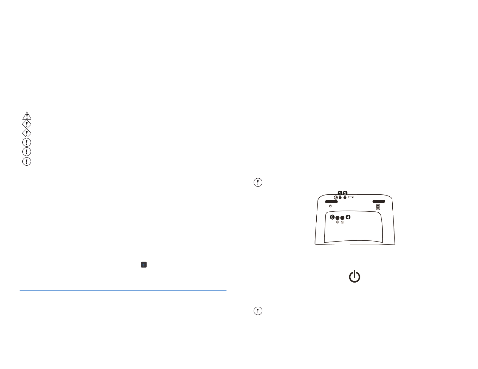
Figure 4: Schematic rendering of MolecuLight i:X Imaging Device showing 1- System Status LED, 2 - Battery Status LED 3- Range Finder
2
max brightness (typical)
LED and 4- Ambient Light Status LED
6.1 Power Button
The MolecuLight i:X Imaging Device has a Power Button for controlling the ON/OFF state of the electronics in the device.
The Power Button can toggle the MolecuLight i:X to one of the following states:
x OFF: the MolecuLight i:X is powered off
x ON: the MolecuLight i:X is powered on (Violet Wavelength LEDs turn on after Fluorescence Imaging Mode is
selected)
TM
MolecuLight i:X
User Manual Revision 1.1 Page 16 of 43
Page 9
Action
Effect
If the MolecuLight i:X is OFF, press and
hold the Power Button for 3 seconds
Switches MolecuLight
If the MolecuLight i:X is ON, press and
hold the Power Button for 3 seconds
Switches MolecuLight
If the MolecuLight
Fluorescence Imaging Mode for greater
than
Switches Violet Wavelength LEDs from ON to OFF automatically (to
conserve battery).
Note You will need to move the Rocker Switch to Standard Imaging
Mode and then back to Fluorescence Imaging Mode to activate the
Violet
Wavelength LEDs.
If the MolecuLig
don’t touch MolecuLight
min
Switches the MolecuLight i:X from ON to OFF automatically after 30
min
position when powering the MolecuLight
Rocker
Imaging Mode to turn on the Violet Wavelength LEDs.
Reset
device or any of its functions are not
functioning as intended)
To reset the MolecuLight i:X, switch the device off, then hold the Power
B
yellow
performed.
Press the Power Button again for 2-3 seconds to turn on the device.
Indicator
Meaning
Solid Green Light
MolecuLight i:X Imaging Device is functioning as expected.
Solid Yellow Light
You can continue imaging, however follow up with MolecuLight as soon as possible.
Solid
The device has malfunctioned. Stop using the device immediately and contact
MolecuLight to troubleshoot the problem.
Red Light, Yellow Light, and 2
Red Light flashes
The device is going through a reset (after the Power Button has been pressed).
Note
When the device is OFF, no System Status LED color is visible. When you power on the device, the
System Status LED
indicates that the device is performing its self-diagnostic routine.
LED Indicator
Meaning
Green Light
The optimal distance (8-12 cm) between MolecuLight i:X and the wound being imaged has been
reached. See Figure 8.
Amber Light
The distance between MolecuLight i:X and the wound is out of its optimal range (i.e. closer than 8 cm
distance. The user can adjust the device-to-wound distance to obtain a Green Light for imaging.
Note
The Range Finder LED turns green when the distance between Range Finder and the wound is within 8-12
cm.
Caution
Capturing a FL-image or FL-video outside the recommended device-to-wound distance may result in
suboptimal fluorescence and/or image quality.
Caution
A defect in the Range Finder’s function may result in distorted/inaccurate images/videos. See Section
15 Troubleshooting & Support, question 18 on how to verify the Range Finder function.
Note
The Ambient Light Status LED is only ON in Standard Imaging Mode. It turns off in Fluorescence Imaging
Mode.
Indicator
Meaning
Green Light
The ambient light level in the imaging environment is adequate for fluorescence imaging.
Amber Light
The ambient light level is too high and fluorescence images should not be captured.
The user should
reduce the ambient light settings by turning off the room lights, blocking windows, turning
off computer monitors
or other means until the Ambient Light Status LED turns green.
Note If you are unable to obtain optimal ambient light for Fluorescence Imaging Mode, MolecuLight
recommends using MolecuLight DarkDrape (used in conjunction with MolecuLight Adapter). For more
information, refer to Section 4.3 or contact MolecuLight.
Note
The Ambient Light Status LED is not active or ON when the Violet Wavelength LEDs are turned on
for imaging in Fluorescence Imaging Mode. In Fluorescence Imaging Mode, the Ambient Light
Status LED is OFF.
Caution
A defect in the Ambient Light Status LED may result in inaccurate images.
Caution
Ignoring the Ambient Light
Status LED indicator may result in inaccurate images.
The Power Button functions as follows:
i:X from OFF to ON.
i:X from ON to OFF.
MolecuLight i:X is equipped with a pulsed laser-based Range Finder sensor which is used to determine the distance
between MolecuLight i:X and the wound. The Range Finder LED indicates to the user when the device is held at the correct
distance for optimal imaging.
i:X is ON during
90 seconds
utes (timing out to conserve battery).
ht i:X is ON and you
utes
i:X for 30
Note If the Rocker Switch is in the Fluorescence Imaging Mode
i:X ON, you need to move the
Switch to Standard Imaging Mode and then back to Fluorescence
function (to be used when the
utton for 8 seconds. The System Status LED will blink red initially, then
and then red again twice. This sequence indicates a reset was
Remove finger from button once this sequence is observed.
Table 8: Power Button functions
6.1.1 Status Indicator LEDs
The MolecuLight i:X is designed with four sensors to guide you in capturing optimal images/videos. Each sensor has a
corresponding indicator light (LED) on the MolecuLight i:X.
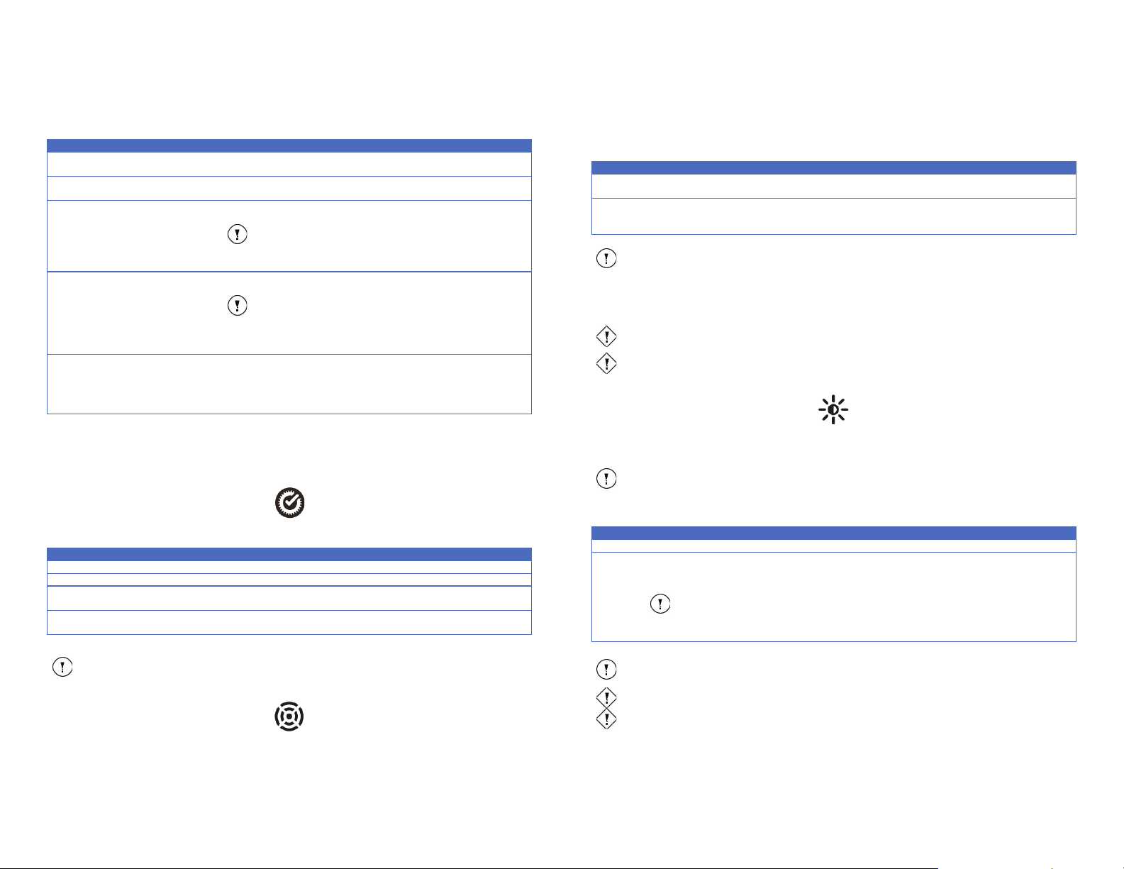
6.1.1.1 System Status LED
MolecuLight
i:X periodically executes a self-diagnosis to ensure it is operating properly. The System Status LED
indicates the overall operational state of the MolecuLight i:X Imaging Device.
Red Light
or further than 12 cm) and/or the Range Finder sensor is unable to determine the device-to-wound
Table 10: Range Finder LED
The Range Finder LED should be used when in FL-Mode. It is also strongly recommended to be used when in STMode to obtain images with similar sizes (for presentation or comparison purposes).
The Range Finder LED should always be used when measuring wound area per Section 10.
6.1.1.3 Ambient Light Status LED
FL-images and FL-videos need to be captured in a dark environment for optimal fluorescence image quality. The Ambient
Light Status LED indicates if the level of ambient light in the examination room is optimal for Fluorescence Imaging to aid
users in capturing optimal fluorescence images and videos.
For use with Fluorescence Imaging Mode, view the Ambient Light Status LED immediately after turning off room lights and
prior to toggling the Rocker Switch to Fluorescence Imaging Mode.
Table 9: System Status LED
blinks green 5 times for 2 seconds, staying solid green on the 5th blink. Blinking
6.1.1.2 Range Finder LED
TM
MolecuLight i:X
User Manual Revision 1.1 Page 17 of 43
MolecuLight i:X
Table 11: Ambient Light Status LED
TM
User Manual Revision 1.1 Page 18 of 43
Page 10
Note
This LED indicates the battery status for the MolecuLight i:X Imaging Device only. The Display
Screen’s battery status and charging status operates independently of this functionality and is
displayed on the screen.
Indicator
Meaning
Solid Green Light
The MolecuLight i:X battery is fully charged or at high power (over 80% power).
Yellow Light
The MolecuLight i:X battery power is between 20-80% power and MolecuLight i:X charging is
advised.
The battery power has dropped below 20% power and the MolecuLight i:X requires immediate
charging.
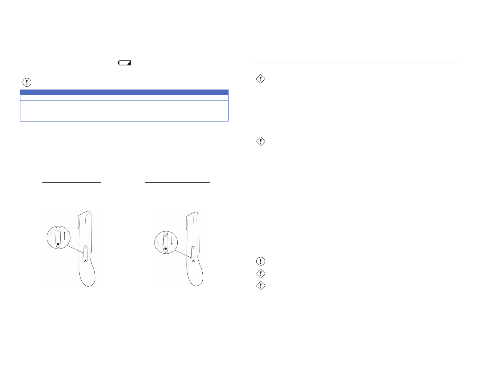
To enable Standard Imaging Mode:
1.
2.
x MolecuLight i:X is in Standard Imaging Mode.
To enable Fluorescence Imaging Mode:
1.
x Violet Wavelength LEDs turn on.
Rocker Switch in Standard Imaging Mode (in ‘up’ position)
Rocker Switch in Fluorescence Imaging Mode (in ‘down’ position)
Caution
MolecuLight i:X is not suitable for use in the presence of flammable anesthetic mixtures with air,
oxygen or nitrous oxide.
Caution
Be aware of surroundings when using the MolecuLight i:X in dark environments during
Fluorescence Imaging Mode. Failure may result in bodily injury due to tripping.
The optical glass windows (see Figure 7) must be clean for optimal Standard Imaging Mode and
Fluorescence Imaging Mode image capture
. Refer to Section 12 for information about cleaning
MolecuLight i:X.
Caution
Patient movement while the device is in close proximity to the patient may result in distorted images.
Caution
Angling the device incorrectly may result in poor image quality. The Illumination Zone on the device
should point directly at wound and be held at the recommended distance.
Failure
to do so may result
in poor image quality. Refer to Figure 8.
6.1.1.4 Battery Status LED
The Battery Status LED indicates the MolecuLight i:X Imaging Device battery charge level.
Solid
Solid Red Light
Table 12: Battery Status LED
When the MolecuLight i:X Imaging Device is OFF, the Battery Status LED is OFF, except when the battery is critically low and
not charging, at which point the LED blinks red every 2 seconds.
When the MolecuLight i:X Imaging Device is charging, the Battery Status LED blinks to indicate charging status of the device.
6.1.2 Rocker Switch
The Rocker Switch enables the user to toggle between Standard Imaging Mode and Fluorescence Imaging Mode.
When the Rocker Switch is in its “down” position, MolecuLight i:X is in Fluorescence Imaging Mode.
When the Rocker Switch is in its “up” position, MolecuLight i:X is in Standard Imaging Mode.
Turn on the device (if it is not already on).
Toggle the Rocker Switch to its “up” position
(Figure 5).
Toggle the Rocker Switch to its “down” position
(Figure 6).
MolecuLight i:X is in Fluorescence Imaging Mode.
x
8 Environmental Conditions That Affect Use
MolecuLight i:X is intended to be used in a hospital/clinical setting.
8.1 Lighting
The level of ambient light in the imaging environment dramatically affects the quality of both the Standard Imaging Mode
and Fluorescence Imaging Mode images acquired with the MolecuLight i:X Imaging Device. A green Ambient Light Status
LED indicates when the lighting conditions are optimal for imaging in Fluorescence Imaging Mode. During Standard Imaging
Mode the Ambient Light Status LED will be amber. Check the Ambient Light Status LED prior to toggling the Rocker Switch to
FL-Mode.
If you are unable to obtain optimal ambient light for Fluorescence Imaging Mode, MolecuLight recommends using
MolecuLight DarkDrape (used in conjunction with MolecuLight Adapter). For more information refer to Section 4.3.
8.2 Operating Temperature
The device is designed to operate in environment temperatures between 10-30oC (50-86oF).
8.3 Storage
Store MolecuLight i:X at room temperature in a secure location between uses.
Store the MolecuLight DarkDrape at room temperature in a dry place.
9 Operating Instructions
9.1 Proper Imaging Technique
A standardized wound imaging protocol is critical to the accuracy and objectivity of digital wound evidence and image
capture. Images should be acquired while holding the device stable in the hands of the user and while the patient is not
moving (to avoid movement artifacts in the images). See Figure 7.
To capture images with MolecuLight i:X (in either Standard Imaging Mode or Fluorescence Imaging Mode):
x Hold the device 8-12 cm away from the wound. The Range Finder LED is green when the distance between
MolecuLight i:X and the wound is optimal.
x Ensure that the wound is centered in the camera’s field of view.
x Hold MolecuLight i:X such that the plane of the wound is parallel to the plane of MolecuLight i:X. See Figure 8.
Figure 5:
7 Quick Start Guide
Please see Appendix C for the MolecuLight i:X Quick Start Guide.
TM
MolecuLight i:X
User Manual Revision 1.1 Page 19 of 43
Figure 6:
Note
TM
MolecuLight i:X
User Manual Revision 1.1 Page 20 of 43
Page 11
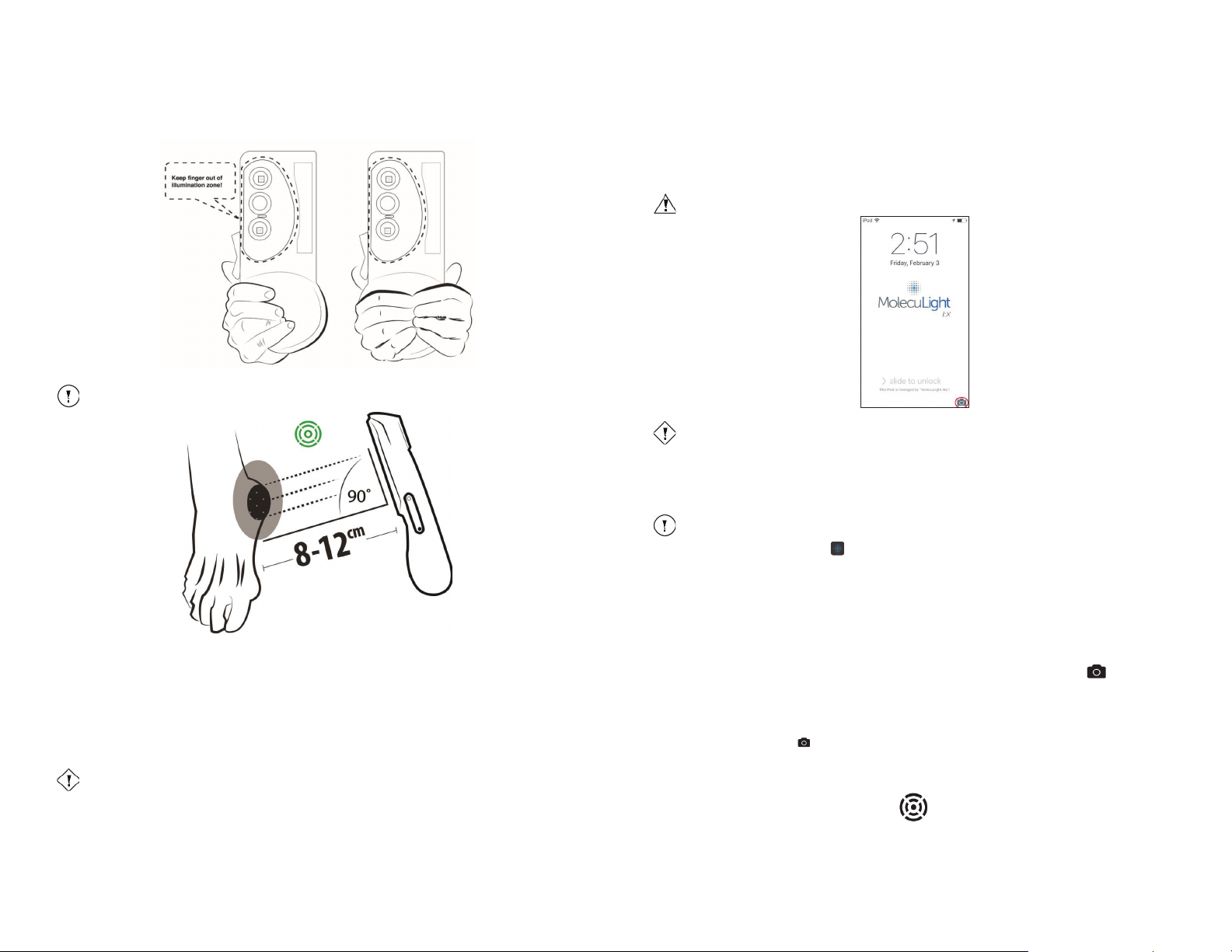
Note
Hands are positioned away from the Violet Wavelength LEDs and are outside of the Illumination
Zone demarcated by the raised ridge.
Caution
Residue from (some) medical gloves on optical components may result in distorted images.
Warning
Only use the
Caution
Do not “swipe up” the camera icon circled in red above. This is not the iX Camera App that is
intended for use.
Note
The MolecuLight i:X Imaging Device and the Display Screen must be powered on. Refer to Section
6.1 for details.
9.3 Imaging with MolecuLight ii:X (iX Camera App)
The MolecuLight iX Camera App is a simple and intuitive application that allows you to quickly and easily capture images
and videos on your MolecuLight i:X Imaging Device.
iX Camera App to capture wound images and/or videos.
Figure 7: How to hold the device with one hand (left) and two hands (right)
Figure 8: Overview of optimal distance and angling of the device relative to the wound
9.2 Handling MolecuLight ii:X
MolecuLight i:X does not require direct contact with the patient or wound during operation. The optimal distance for
imaging is 8-12 cm from the wound.
MolecuLight i:X does not require the administration of any exogenous imaging contrast agents for imaging in Fluorescence
Imaging Mode.
MolecuLight i:X can be easily cleaned between uses. Instructions for cleaning and disinfection can be found in Section 12.
MolecuLight recommends the use of standard powder-free latex or nitrile gloves when using MolecuLight i:X to reduce the
risk of bacterial contamination.
Figure 9: Display Screen
The iX Camera App is easily accessible by following two simple steps:
1. Push the Home Button on the MolecuLight i:X.
The MolecuLight i:X Display Screen turns on.
If the screen is locked, use ‘slide to unlock’ at the bottom of the display to unlock the screen.
2. Press the iX Camera App icon.
The iX Camera App opens and is ready for use.
The iX Camera App allows you to:
x Capture an image
x Capture a 30 second video
x Review previously acquired images/videos via Image Library
x Delete images/videos
9.3.1 Capture an Image
The iX Camera App allows you to capture both a ST-image and FL-image by selecting the Camera icon.
9.3.1.1 Capture an ST-image
To capture an image in Standard Imaging Mode:
1. Move the Rocker Switch to the Standard Imaging Mode position.
2. Select the Camera icon. The Camera icon turns blue when selected.
3. When using the iX Camera App wound measurement functionality, refer to instructions provided in section 10
and Appendix E.
4. View the Range Finder LED.
TM
MolecuLight i:X
User Manual Revision 1.1 Page 21 of 43
MolecuLight i:X
TM
User Manual Revision 1.1 Page 22 of 43
Page 12
Caution
Hold MolecuLight
i:X steady while imaging; shaking hands may result in distorted images.
If lights cannot be turned off, use (optional) MolecuLight DarkDrape and MolecuLight Adapter. Refer to
Section 4.3 for details.
Caution
Do not use MolecuLight WoundStickers when capturing images in Fluorescence Imaging Mode.
Caution
Covering LEDs with your fingers will result in poor image quality. The Illumination Zone on MolecuLight
i:X (see Figure 7) represents the intended keep-out zone for the LEDs.
Note
Monitor the Range Finder LED throughout the whole video recording session to maintain an appropriate
imaging distance.
Note
30 seconds is the maximum video length that can be acquired
Note
Images and videos are saved in
If lights cannot be turned off, use (optional) MolecuLight DarkDrape and MolecuLight Adapter. Refer to
Section 4.3 for details.
Caution
Do not use MolecuLight WoundStickers when capturing images in Fluorescence Imaging Mode.
Note
Monitor the Range Finder LED throughout the whole video recording session to maintain an
appropriate imaging distance.
The Range Finder LED advises when the optimal distance between (8-12 cm from the wound) the target and
MolecuLight i:X is reached. If you wish to capture images in FL-Mode and ST-Mode with similar fields of view, this
feature will be critical to observe.
5. Aim the MolecuLight i:X Imaging Device towards the wound (with the screen facing the user) and center the
wound in the camera’s field of view.
A square briefly appears in the center of the field of view to indicate that the camera focus is being set. If the
autofocus is not satisfactory, tap on the screen on the target of interest to manually focus on the wound.
6. To take an image, tap anywhere within the blue rectangle indicating ‘CAPTURE IMAGE’.
You will hear a click sound and the screen will flash indicating that the ST-image was captured and saved on the
MolecuLight i:X.
9.3.1.2 Capture an FL-image
To capture an image in Fluorescence Imaging Mode:
1. Turn off the lights in the examination room. A dark environment is required to capture a good quality image.
Note
2. View the Ambient Light Status LED.
3. The Ambient Light Status LED provides feedback as to whether or not the ambient light level is optimal. The
green color indicates that conditions are optimal to capture an image. If the LED is amber, try turning off
additional light sources (e.g. computer monitors) and covering windows until the LED turns green or use a
MolecuLight DarkDrape.
4. Move the Rocker Switch to the Fluorescence Imaging Mode position.
5. Select the Camera icon and ensure you are already within the iX Camera App.
If the Display Screen is off, press the Home Button to access the iX Camera App icon.
6. View the Range Finder LED.
The Range Finder LED advises when the optimal distance (8-12 cm from the wound) between the target and
MolecuLight i:X is reached. The Range Finder LED is green when the distance is optimal.
7. Aim MolecuLight i:X towards the wound (with the screen facing the user). A square briefly appears in the center
of the field of view to indicate that the camera focus is being set. If the autofocus is not satisfactory, tap on the
screen on the target of interest to manually focus on the wound.
8. To take an image, tap anywhere within the blue rectangle indicating ‘CAPTURE IMAGE’.
You will hear a click sound and the screen will flash indicating that the FL-image was captured and saved on the
MolecuLight i:X.
2. Select the Video icon. The Video icon turns blue when selected.
3. View the Range Finder LED.
4. The Range Finder LED indicates when the optimal distance between (8-12 cm from the wound) the target and
MolecuLight i:X is reached. If you wish to capture videos in FL-Mode and ST-Mode with similar fields of view,
this feature will be important to use.
5. Aim MolecuLight i:X towards the wound.
A square briefly appears in the center of the field of view to indicate that the camera focus is being set. If the
autofocus is not satisfactory, tap on the screen on the target of interest to manually focus on the wound.
6. To take a video, tap anywhere within the blue rectangle indicating ‘START RECORDING’.
The ST-video begins recording and a time counter will appear on the screen.
7. To stop the recording, tap the screen within the blue rectangle indicating ‘STOP RECORDING’. The time counter
stops.
The ST-video stops recording and is saved on the MolecuLight i:X.
at one time.
the Image Library.
9.3.1.5 Capture an FL-video
To capture a video in Fluorescence Imaging Mode:
1. Turn off the lights in the examination room. A dark environment is required to capture a good quality image.
Note
2. View the Ambient Light Status LED.
The Ambient Light Status LED provides feedback as to whether or not the ambient light level is optimal. If the
LED is amber, try turning off additional light sources (e.g. computer monitors) and covering windows until the
LED turns green, or use the MolecuLight DarkDrape.
3. Move the Rocker Switch to the Fluorescence Imaging Mode position (see Figure 6).
4. Select the Video icon. The Video icon is blue when selected.
5. View the Range Finder LED.
The Range Finder LED advises when the optimal distance (8-12 cm from the wound) between the target and
MolecuLight i:X is reached. The Range Finder LED is green when the distance is optimal.
9.3.1.3 Capture a video
The iX Camera App allows you to capture both an ST-video and FL-video by selecting the Video icon.
9.3.1.4 Capture an ST-video
To capture a video in Standard Imaging Mode:
1. Move the Rocker Switch to the Standard Imaging Mode position.
TM
MolecuLight i:X
User Manual Revision 1.1 Page 23 of 43
6. Aim MolecuLight i:X towards the wound. A square briefly appears in the center of the field of view to indicate
that the camera focus is being set. If the autofocus is not satisfactory, tap on the screen on the target of interest
to manually focus on the wound.
7. To take a video, tap anywhere within the blue rectangle indicating ‘START RECORDING’.
The FL-video begins recording and a time counter appears on the screen.
TM
MolecuLight i:X
User Manual Revision 1.1 Page 24 of 43
Page 13
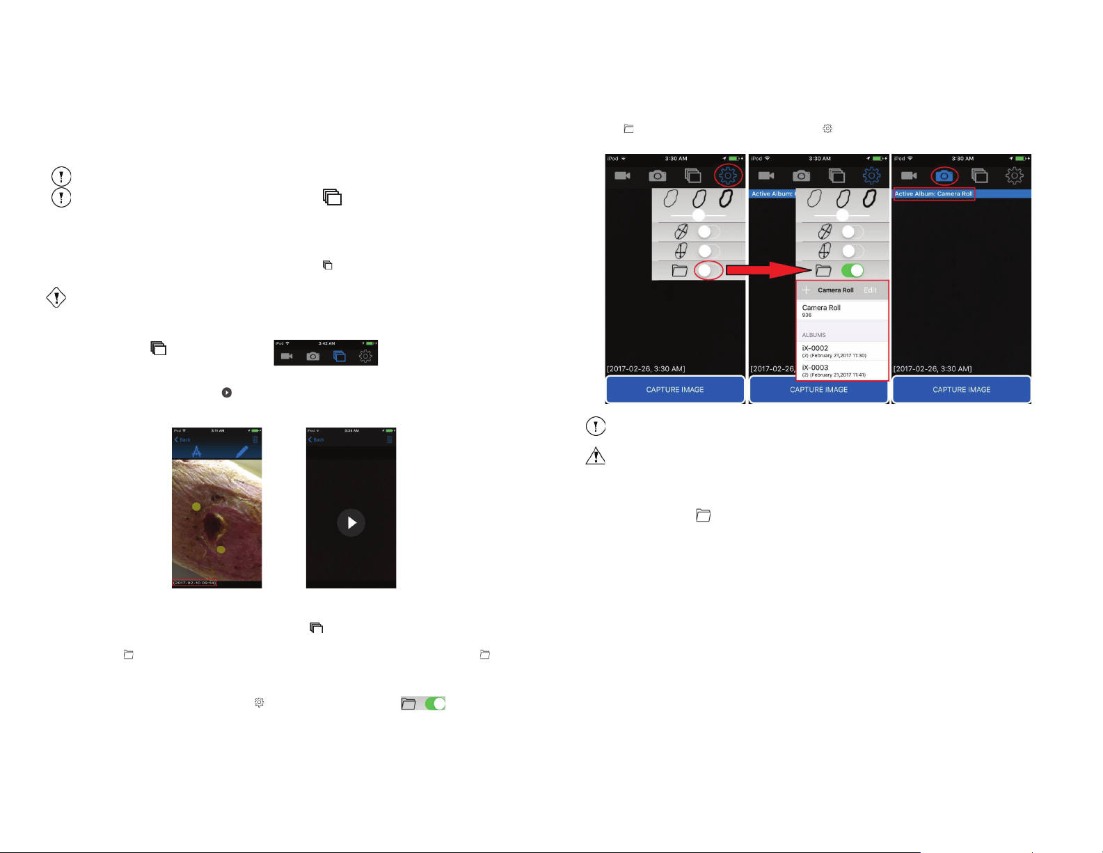
Note
30 seconds is the maximum video length that can be acquired at one time.
Note
Images and videos are saved in
the Image Library.
Caution
There may be a minor delay once the Image Library icon is selected before the image thumbnails appear.
Figure 10: Viewing a Saved Image
Figure 11: Viewing a Saved Video
The Active Album must be selected prior to taking images/videos. Images/videos cannot be moved
between Albums.
Warning
Due to iOS restrictions, when downloading images to a computer through explorer/finder, individual
albums will not appear and users may manually sort photos using the unique image ID text overlay
saved on images.
8. To stop the recording, tap the screen within the blue rectangle indicating ‘STOP RECORDING’ and the time
counter will stop.
The FL-video stops recording and is saved on the MolecuLight i:X.
9.4 Review Images and/or Videos Using the Image Library
The iX Camera App allows you to browse through the Image Library and view individual images/videos.
By default, the Image Library displays all images and videos that have been saved. The most recently saved image/video is
displayed at the bottom of the Image Library. When the Image Library icon is selected, all images/videos appear in
thumbnail format and are available for review.
Swipe up or down to scroll through recent images/videos in the Image Library. Swiping down scrolls to older
image(s)/video(s) and swiping up scrolls to newer image(s)/video(s).
Select the Image Library icon from the Menu Bar to view previously acquired images
and videos.
1. Tap the thumbnail of an image/video of interest and the selected image/video is displayed.
A video is indicated by the overlaid play icon as depicted in Figure 11.
2. The date and time of acquisition is always saved with the image in the bottom left corner as depicted in Figure 10.
This is only applicable to saved images. Acquired videos are not saved with the date and time of acquisition.
9.5 Using the Album Feature (Optional)
All acquired images/videos can be browsed from the Image Library where images/videos are saved sequentially per
section 9.4.
The optional Album feature is for users who wish to save images and videos into particular folders. The Album feature
provides an easy and convenient way to save images and videos together by creating and designating an Active Album.
An Active Album simply means that newly acquired images and videos will be added to the Active Album selected.
To enable the Album feature, open the Settings Menu and tap the Album Feature switch:
When the Album feature is enabled, the default Active Album to view saved images/videos on the MolecuLight i:X is the
Camera Roll as depicted in Figure 12.
MolecuLight i:X
TM
User Manual Revision 1.1 Page 25 of 43
The Album feature may be selected from the Settings Menu where previously created Albums may be browsed and
selected to become the “Active Album” at any time.
Figure 12: Enabling the Optional Album Feature
Note
9.5.1 Creating a New Album
To create a new Album:
1. Enable the Album icon and select ‘+’
2. Select ‘Create’ when prompted with ‘Create New Album: iX-….?’
3. The new Album is designated as the Active Album where subsequent images and videos will be saved.
A description below the Album name provides information about the number of images and videos and the time and
date of the last acquired image within a particular album.
4. The iX Camera App automatically generates the Album name with prefix ‘iX-’ followed by the next 4-digit number in
the sequence. Note that Album names cannot be edited.
5. As depicted in Figure 13, a unique Image ID containing the Album name followed by “photo number” appears on the
bottom left side of the image along with the date and time of acquisition. This Image ID will appear at the bottom of
the saved photo and will automatically increment each time a new photo is taken.
TM
MolecuLight i:X
User Manual Revision 1.1 Page 26 of 43
Page 14
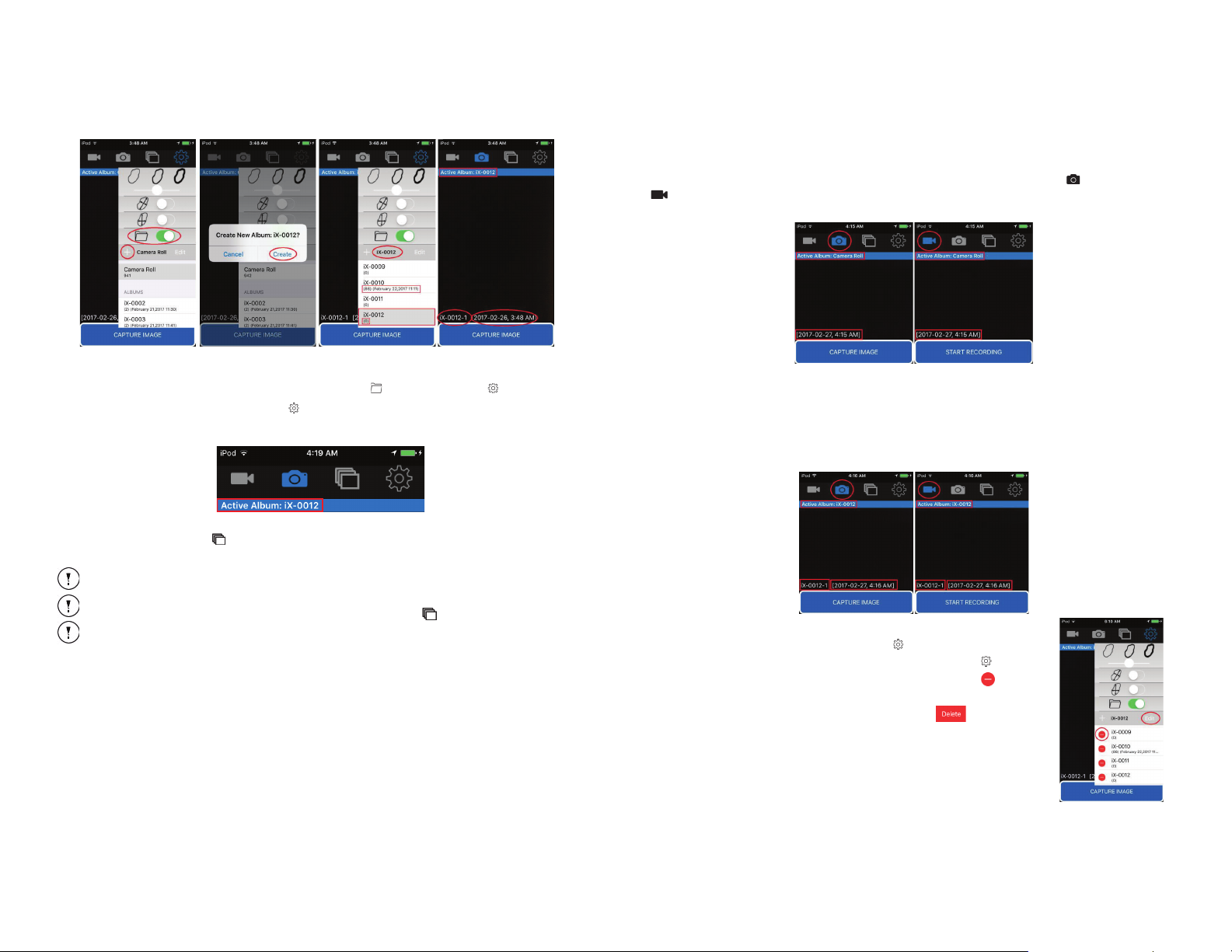
Note
Images and videos captured in a designated Active album cannot be
Note
At any time, the user may go back to the Settings icon to disable the Album feature. When disabled, all
acquired images and videos can be browsed from the Image Library .
Note
When the total number of created Albums reaches 9999, a new Album “iX-0001” shall be created even if
an old Album with the same name exists. This does not overwrite the previous Album.
Figure 14: Menu Bar
Figure 15: Capture Screens with
Figure 16: Capture Screens with
Created Album as Active Album
Figure 17: Deleting Albums
9.5.3 Capture Image and Video Capture Screens
9.5.3.1 Capture Screens when the Active Album is the Camera Roll
When the Album feature is enabled with the Camera Roll as the Active Album, the Capture Image and Video Capture
screens display the Active Album “Camera Roll” across the top of the image, and the date and time of acquisition
across the bottom left side of the image as depicted in Figure 15.
Camera Roll as Active Album
Figure 13: Creating a New Album
9.5.2 Accessing and Using Previously Created Albums
To add new images to a previously created Album, enable the Album icon from the Settings Menu :
1. Select the desired Album from the Settings Menu drop down list (as depicted above).
The selected Album will be highlighted grey.
2. The selected Album becomes the Active Album and is labelled as the ‘Active Album’ across the Menu Bar:
Newly acquired images and videos will be saved to the Active Album.
When browsing the Image Library with an Active Album designated, only images and videos saved to the selected
Active Album are displayed in the Image Library. All acquired images and videos can always be found on the Camera Roll.
TM
MolecuLight i:X
User Manual Revision 1.1 Page 27 of 43
moved into another Album.
9.5.3.2 Capture Screens when the Active Album is Created
When created Albums are used as the Active Album instead of the Camera Roll, a unique Image ID correlating to the Album
name followed by “photo number” appears on the bottom left side of the image in addition to the date and time of
acquisition.
As depicted in Figure 16, this Image ID will appear at the bottom of the saved image and will automatically increment each
time a new image/video is taken. Although the Image ID and date and time of acquisition is displayed during Video Capture,
videos are not saved with an Image ID or date and time of acquisition.
9.5.4 Deleting Albums
With the Album feature enabled from the Settings Menu :
1. Delete an Album by selecting the ‘Edit’ function within the Settings Menu .
2. If user selects the ‘Edit’ button, a minus sign appears next to each Album:
To exit the ‘Edit’ function, tap the ‘Edit’ button again.
3. When the minus sign is selected, a ‘Delete’ button will appear:
4. If ‘Delete’ button is selected a confirmation message appears.
5. Once user confirms to delete the Album, they will be asked whether or not to also delete
the images within that Album.
If user chooses not to delete the images after the Album is deleted, the images will be
found in the Camera Roll.
TM
MolecuLight i:X
User Manual Revision 1.1 Page 28 of 43
Page 15
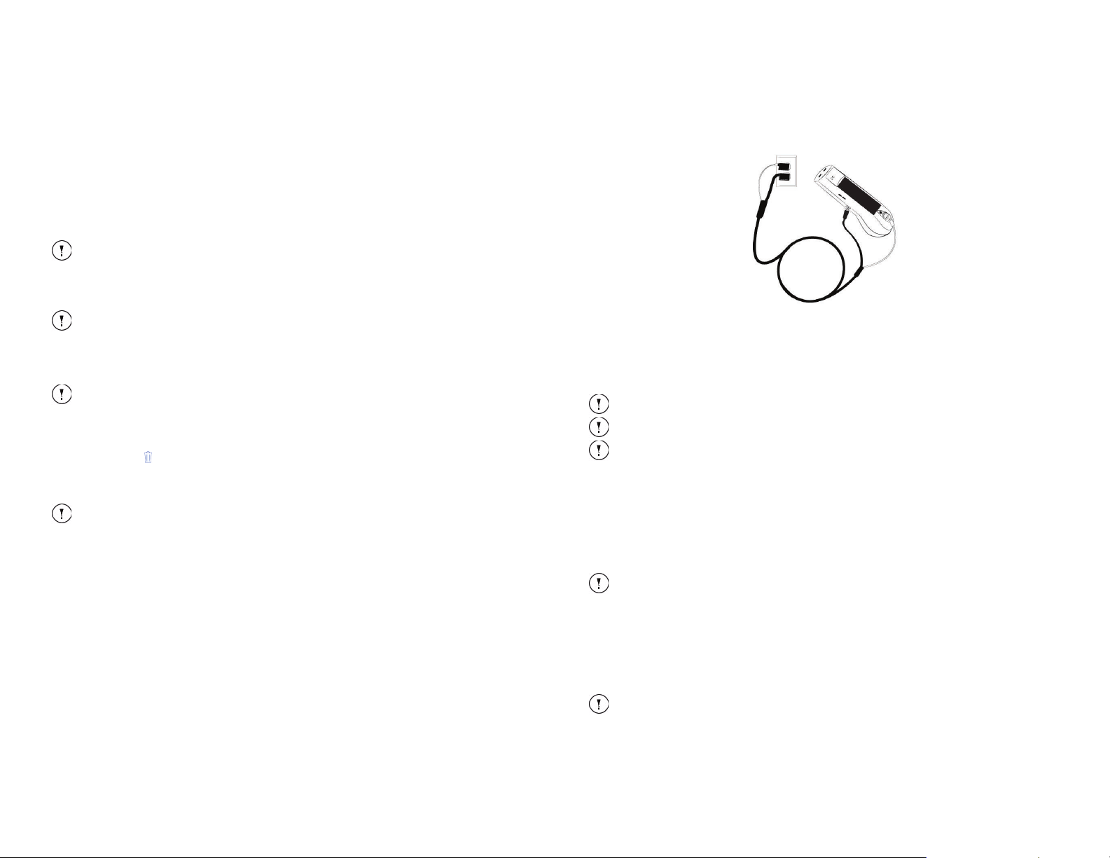
Note
The speed at which your fingers spread influences the rate of zoom.
Note
It is not possible
to zoom in and out on video recordings.
Note
It is only possible to pan a displayed ST-image or FL-image that has been zoomed. It is not possible to
pan a recorded video. It is not possible to pan during image capture.
Note
Images are not permanently deleted using this method. Images can still be recovered on the device
from the deleted images folder.
i:
Note
Connection to wall outlet should be easily and readily accessible and not blocked when MolecuLight i:X
requires charging.
Note
MolecuLight recommends charging the MolecuLight i:X whenever it is not in use so that it is fully charged
for its next use.
Note
It takes up to 5 hours to fully charge the MolecuLight i:X once it is fully depleted. It takes approximately 2
hours to charge to 80%.
Note
MolecuLight recommends charging the MolecuLight i:X Display Screen whenever it is not in use so that it
is fully charged for its next use.
Note
If the USB connector end of the white connecting cable is connected to the USB power adapter,
disconnect it.
9.6 Zooming in and out and Panning
9.6.1 Zooming in and out
To zoom in and out on a displayed image:
1. Select the image. The image will fill the full screen.
2. Place your thumb and pointer finger at opposing points of the image.
3. Keep both fingers on the screen and gently move your fingers away from each other.
This action “zooms in” on the part of the image between the two fingers, enlarging the portion of the image between
the two fingers.
4. To zoom back out, reverse the motion and gently "pinch" your fingers towards each other while keeping contact with
the screen.
This action “zooms out” on the part of the image between the two fingers, reducing the display of the portion of the
image between the two fingers.
9.6.2 Panning
To pan a displayed image:
On a zoomed in image, drag the screen with one finger to move around the image or hold your finger near the edge of the
screen to pan to that side. Move your finger closer to the edge to pan more quickly.
9.7 Deleting Images and Videos
To delete an image or video:
1. Select the image or video on the Display Screen.
2. Tap the Trash icon.
You will be prompted with “Allow ‘iX Camera’ to delete this photo?” or “Allow ‘iX Camera’ to delete this video?”
3. Select either ‘Don’t Allow’ or ‘Delete’.
Selecting ‘Delete’ will delete the image or video.
9.8 Charging MolecuLight
The Display Screen and the MolecuLight i:X Imaging Device each contain a rechargeable battery. Both batteries need to be
charged separately in order for MolecuLight i:X to work properly. The cables for charging both batteries are provided as one
item (MolecuLight Power Cable) so that the MolecuLight i:X Imaging Device and Display Screen may be charged
concurrently. Geography-specific MolecuLight Power Cable Adapters (supplied) may be required to connect the
MolecuLight Power Cable to the wall outlet.
X
9.8.1 Charge the MolecuLight ii:X Imaging Device
To charge the MolecuLight i:X Imaging Device:
1. Connect the MolecuLight i:X Imaging Device to the black power supply cable on the MolecuLight Power Cable (P/N
Figure 18: Charging MolecuLight i:X Imaging Device and Display Screen with MolecuLight Power Cable
1142) as in Figure 18. The black power supply cable charges the MolecuLight i:X Imaging Device.
The MolecuLight i:X Imaging Device begins charging. The Battery Status LED indicates the battery power as described in
Section 6.1.1.4.
2. When the Battery Status LED is solid green and no longer blinking, disconnect the MolecuLight Power Cable from the
wall. Then remove the black power supply cable from the device and store the MolecuLight i:X for its next use.
9.8.2 Charge the MolecuLight i:X Display Screen
To charge the MolecuLight i:X Display Screen:
1. Connect the white connecting cable on the MolecuLight Power Cable (P/N 1142) to the port on the MolecuLight i:X
Display Screen as shown in Figure 18.
2. Connect the USB power adapter to the other end of the white connecting cable as shown in Figure 18.
3. Plug the USB power adapter into an electrical outlet.
4. When the battery status on the Display Screen indicates that it is fully charged, disconnect the MolecuLight Power Cable
from the electrical outlet and then remove the MolecuLight Power Cable from the device.
9.9 Uploading Images and Videos to Computer
You can upload images and videos to a computer using supported applications on your Mac or PC.
To upload images and videos to a computer:
1. Connect the white connecting cable on the MolecuLight Power Cable (P/N 1142) to the port on the MolecuLight i:X
Display Screen. Connect the USB connector end of the white connecting cable to your computer as shown in Figure 19.
When prompted to ‘allow’ or ‘trust’ the computer on the MolecuLight i:X Display Screen, you may do so.
Communication between MolecuLight i:X and your computer will be established automatically.
TM
MolecuLight i:X
User Manual Revision 1.1 Page 29 of 43
2. Do not use iTunes to copy or move images from MolecuLight i:X to your computer. If you have iTunes on your
computer, you will automatically be prompted to access the images/videos via iTunes.
TM
MolecuLight i:X
User Manual Revision 1.1 Page 30 of 43
Page 16
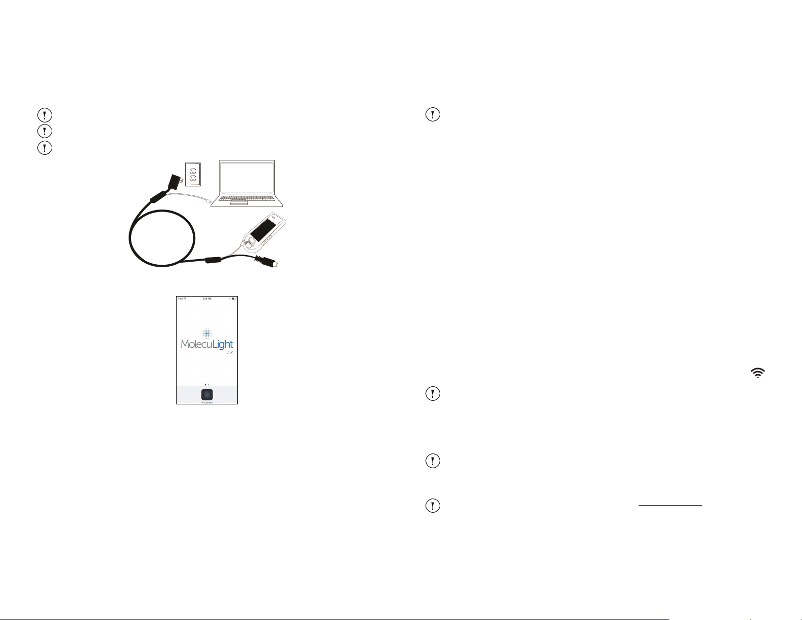
Note
If you delete photos or videos during data
Note
Images are not permanently deleted using this method. Images can still be recovered on the device from
the deleted images folder.
Note
You will require an Apple ID (consult with your Institution’s IT department), for accessing future
MolecuLight Apps.
Note
The Display Screen locks automatically if you don’t touch the screen for 5 minutes.
Note
If you leave proximity to a connected Wi-Fi network and lose the connection to it, MolecuLight i:X
reconnects when you return to the same location.
Note
It is advised to follow your IT department protocol before setting up a
Note
If a cybersecurity breach is suspected contact MolecuLight at [email protected] or call +1-647-3624684, or 1-877-818-4360 (North America Only).
3. Close the iTunes window, select Finder (Mac) or Windows Explorer (PC) and select the MolecuLight Device under
Portable Devices. You will be able to access your images within the MolecuLight Device folder.
transfer, they are removed from the Image Library.
Figure 19: Connecting MolecuLight i:X to a computer to transfer images/videos
9.10 Display Screen Functionality
To lock the Display Screen:
1. Press the Display Screen Power Button. The MolecuLight i:X screen becomes dark and the device is locked.
To unlock the Display Screen:
1. Press the Home Button.
2. Drag the ‘slide to unlock’ slider to the right. The MolecuLight i:X unlocks.
To turn on the Display Screen:
1. If the Display Screen has been fully powered off, press and hold the Display Screen Power Button.
2. When the Apple logo appears, wait for the MolecuLight i:X Display Screen to power on.
3. When the ‘slide to unlock’ slider appears, drag the ‘slide to unlock’ slider to the right which unlocks the MolecuLight i:X,
and access the iX Camera App
To turn off the Display Screen:
1. Press and hold the Display Screen Power Button.
2. When the ‘slide to power off’ slider appears, then drag the slider to the right.
3. The MolecuLight i:X Display Screen powers off.
.
9.10.2 Connect to a Wi-Fi Network
MolecuLight i:X contains a 2.4GHz Wi-Fi module. Wi-Fi is a technology that allows you to wirelessly connect to a local-area
network.
To connect to a Wi-Fi network:
1. From the MolecuLight i:X Home Screen, swipe right to the center page and tap Settings.
The Settings screen is displayed.
2. Tap Wi-Fi.
The Wi-Fi screen is displayed.
3. Slide the Wi-Fi ON/OFF switch to ON.
MolecuLight i:X automatically searches for available Wi-Fi networks.
4. Tap the name of your desired Wi-Fi network.
5. If the Wi-Fi network is password-protected, a prompt appears to enter a password.
6. Enter the password for the Wi-Fi network.
7. Tap Join.
When your device is connected to a Wi-Fi network, a checkmark appears to the left of the network name. The Wi-Fi
symbol also appears in the status bar at the top left of your display.
Figure 20: MolecuLight i:X Display Screen
9.10.1 Basic Display Screen Functionality for MolecuLight ii:X Use
Most of the buttons required to use the Display Screen are located on the touchscreen user interface.
The Home Button is the only physical button that controls the Display Screen.
9.10.1.1 Home Button
Pressing the Home Button takes you to the Home Screen and provides access to the iX Camera App.
You are able to lock the Display Screen while not using the MolecuLight i:X. Locking the Display Screen saves battery life and
prevents the device from responding if you inadvertently touch the screen.
TM
MolecuLight i:X
User Manual Revision 1.1 Page 31 of 43
9.10.3 Connect to the Internet
MolecuLight i:X connects to the Internet by joining Wi-Fi networks. When joined to a Wi-Fi network that is connected to the
Internet, MolecuLight i:X connects to the Internet automatically.
9.10.4 Create a Passcode
passcode.
Default factory settings for the MolecuLight i:X Imaging Device do not require the use of a passcode.
To prevent unauthorized access to data acquired on the MolecuLight i:X you may want to create a passcode.
To create a passcode for MolecuLight i:X, go to Settings > Passcode.
TM
MolecuLight i:X
User Manual Revision 1.1 Page 32 of 43
Page 17
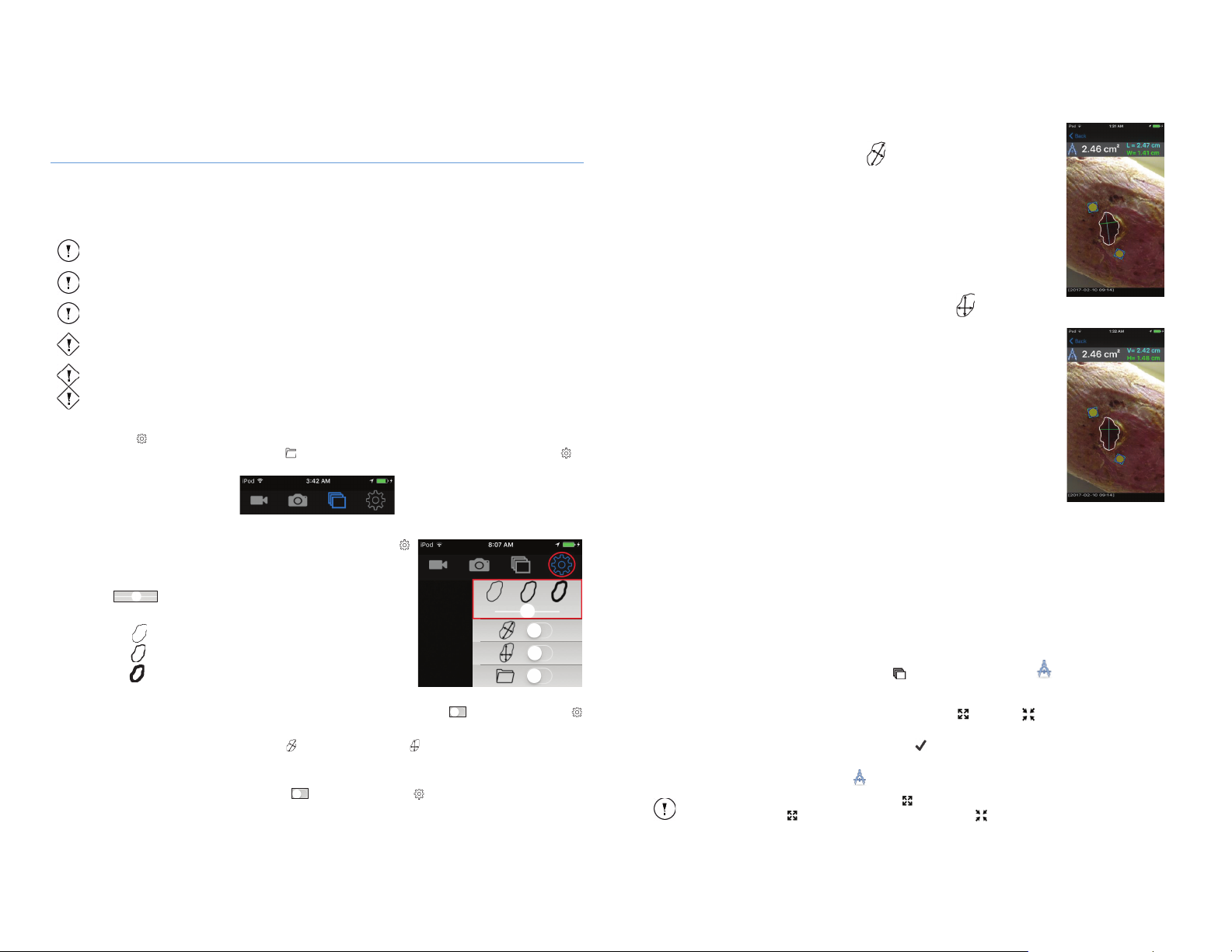
Figure 21: Settings Menu
The wound measurement functionality should only be used on images captured in Standard Imaging
Mode and should not be used on images captured in Fluorescence imaging mode.
The use of 2 MolecuLight WoundStickers may produce an average wound measurement error (Area
and Dimension)
of 5%, when the image is taken with MolecuLight WoundStickers in the plane of the
wound.
In the absence of MolecuLight WoundStickers, no
area measurement is provided.
Caution
The use of only 1 MolecuLight WoundSticker may produce an average wound measurement error (Area
and Dimension)
of 15%, when the image is taken with MolecuLight WoundStickers in the plane of the
wound.
Caution
Only MolecuLight WoundStickers should be used for the wound measurement functionality.
Caution
Do not place MolecuLight WoundStickers on the wound.
Note
Once the user has pressed the Expand icon until it reaches the largest detection threshold range,
the Expand icon will disappear, leaving the Contract icon.
Figure 22: Length & Width
Figure 23: Vertical & Horizontal
10 Measuring Wound Area
The iX Camera App wound measurement functionality features wound border detection, wound area measurement, and
wound length & width measurement capabilities. The wound border may be traced automatically (Auto Mode) or manually
(Manual Mode). Wound area measurement should only be performed on images captured in Standard Imaging Mode with
the use of MolecuLight WoundStickers. Refer to Appendix E for additional details on the iX Camera App wound
measurement functionality.
Note
Note
Note
10.1 Settings Menu
The Settings Menu accessed from the Menu Bar enables customization of the wound border thickness, and display of
reported length and width dimensions. The Album feature may also be enabled through the Settings Menu as
described in Section 9.5.
10.1.1 Wound Border Thickness
The displayed wound border thickness can be modified from the Settings Menu
accessed from the Menu Bar.
By default, the medium border thickness is selected.
Use the slider to modify the border thickness to the desired setting.
The 3 available settings are
1) Thin
2) Medium
3) Thick
10.1.2 Display of Length & Width Dimensions
The display of the Length and Width dimensions can be disabled or enabled using the switch from the Settings Menu
accessed from the Menu Bar.
When enabled, a selection between “Length & Width” or “Vertical & Horizontal” can be made. By default, the “Length
& Width” setting is enabled where the maximum length and perpendicular width of the wound is displayed on screen
whenever a wound measurement is taken.
When display of dimensions is disabled using the switch from the Settings Menu , length/width or vertical/horizontal
dimensions will no longer be reported on the wound image when a wound border is drawn and saved.
TM
MolecuLight i:X
User Manual Revision 1.1 Page 33 of 43
10.1.2.1 Length & Width
By default, the Length & Width setting is enabled:
Once the desired wound border is drawn, Length & Width dimensions will appear as blue and
green lines on the wound and their measurements will be reported in cm.
Wound length (blue line, L) represents the longest dimension of the wound in any direction.
Wound width (green line, W) is drawn perpendicular to wound length.
As wounds change in size over time the orientation of the maximum length of the wound may
also shift and therefore the maximum length may not always be reported from the same part
of the wound using this length and width option.
10.1.2.2 Vertical & Horizontal
Wound dimensions are also available in vertical and horizontal format:
Vertical length (blue line, V) represents the longest vertical distance (top to bottom of the
screen) within the wound boundary. Horizontal length (green line, H) represents the longest
horizontal distance within the wound boundary.
Selecting this method of measuring wounds will allow you to consistently measure the same
axes of the wound for tracking changes in vertical and horizontal wound distances over time.
To measure the wound consistently, wound images must be taken with consistent orientation.
This method of measurement can be combined with the well documented clock method to
accurately detect changes in the vertical and horizontal distances of the wounds.
To take measurements according to the clock method, capture wound images with the
MolecuLight i:X in a portrait orientation such that the top of the device is aligned with the head
of the patient and the bottom with the feet of the patient. The measured vertical distance will
be a measurement of the wound from 12-6 o’clock and the horizontal distance will be a
measurement of the wound from 9-3 o’clock.
10.2 Auto Mode
The iX Camera App can automatically trace and measure the area of a wound. The following steps are required for
automated wound area measurements:
1. Ensure the Standard Imaging Mode wound image is captured with 2 MolecuLight WoundStickers (P/N 1266) placed
close to and within the plane of the wound. Measurement accuracy will be degraded if the MolecuLight WoundStickers
are off plane, in which case stickers may appear elliptical. For optimal results, ensure the MolecuLight WoundSticker
placement is at the 1 and 7 o’clock position or at the 11 and 5 o’clock position when holding the MolecuLight i:X in a
portrait (vertical) orientation, as depicted in Figure 22 and Figure 23.
2. When capturing an image, ensure the MolecuLight i:X Camera Sensor is parallel to the wound and the MolecuLight
WoundStickers are in field of view.
3. Open the image of interest from the Image Library . Select the Auto Trace icon.
4. The Auto Trace feature traces the border of the wound with a white line (the MolecuLight WoundStickers will be
highlighted with a blue circle during this auto detection process).
5. When selecting Auto Trace, additional icons are available to expand or contract the detected border. Pressing
these icons expands or contracts the wound border as desired.
6. Once the desired wound border is achieved, a Checkmark icon is available to ‘Accept and Save’ the wound border
and the wound area will appear in cm
At any point, the user can select the Auto Trace icon to exit Auto Mode.
TM
MolecuLight i:X
User Manual Revision 1.1 Page 34 of 43
2
.
Page 18
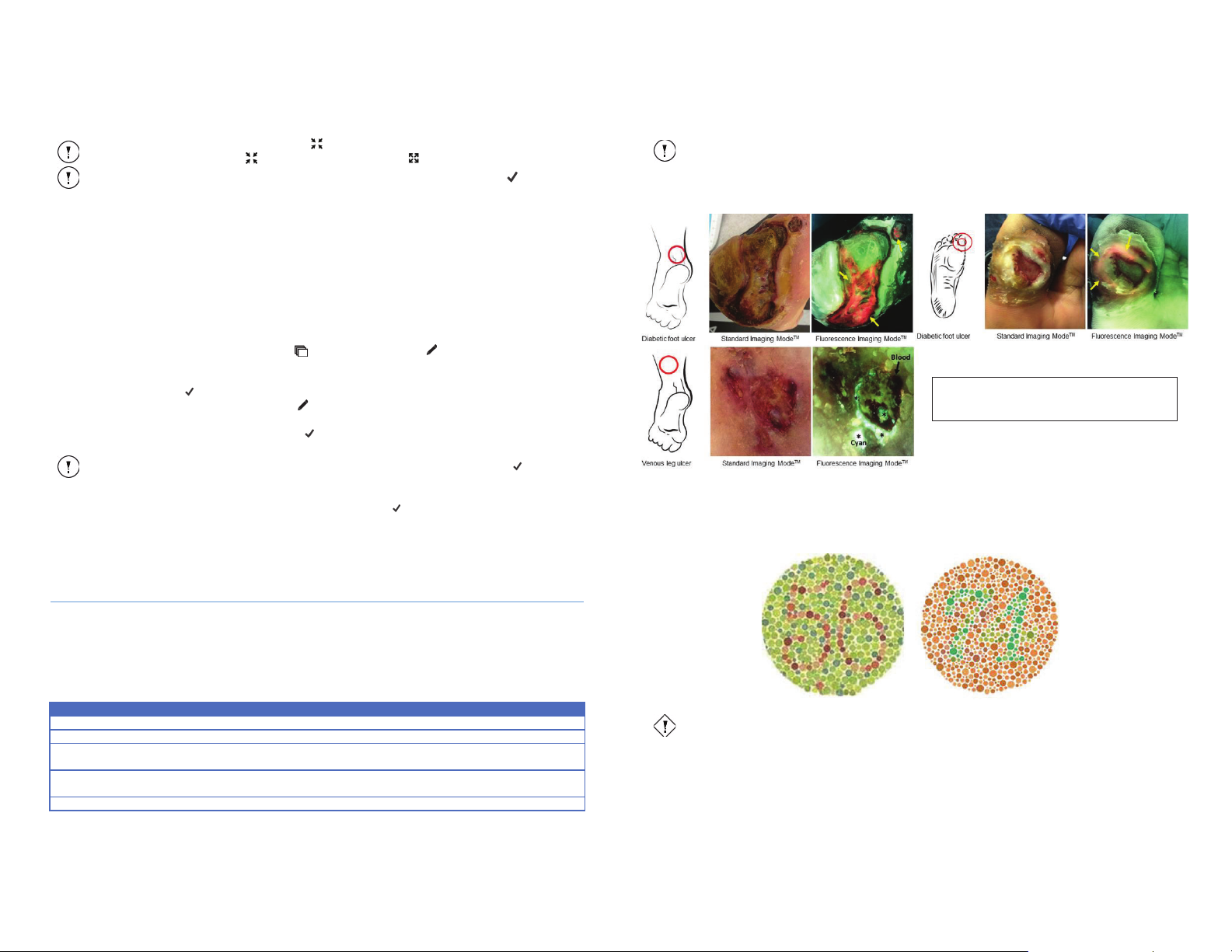
Note
Once the user has pressed the Contract icon until it reaches the smallest detection threshold
range, the Contract icon will disappear, leaving the Expand icon.
Note
T
he wound area measurement is not displayed unless the user selects the Checkmark icon.
Note
T
Color
Indicator
Red*
Typically associated with the presence of potentially harmful levels of bacteria
Green
Typically associated with connective tissues in skin
Dark/black areas
Typically associated with blood, highly vascularized tissues, necrotic tissue, highly pigmented tissue
(freckles, moles, etc.) or poorly illuminated areas
White
Typically associated with materials in the field of view that are white (bed sheet, clothing, paper,
wound measuring ruler, etc.) or oversaturation of color signal
Cyan
Typically associated with the presence of Pseudomonas aeruginosa
Note*
Red color of bacteria may appear orange to some users.
Caution
MolecuLight
Figure 24: Examples of MolecuLight i:X images in Standard
Imaging Mode and Fluorescence Imaging Mode. Red color
indicates the presence of bacteria (shown by arrows).
10.3 Manual Mode
If Auto Mode is not tracing an accurate wound boundary, the iX Camera App also allows for manual tracing of the wound
border to measure wound area. The following steps are required for manual wound area measurements:
1. Ensure the Standard Imaging Mode wound image is captured with 2 MolecuLight WoundStickers (P/N 1266) placed
close to and within the plane of the wound. Measurement accuracy will be degraded if the MolecuLight WoundStickers
are off plane, in which case stickers may appear elliptical. For optimal results, ensure the MolecuLight WoundSticker
placement is at the 1 and 7 o’clock position or at the 11 and 5 o’clock position when holding the MolecuLight i:X in a
portrait (vertical) orientation, as depicted in Figure 22 and Figure 23.
2. When capturing an image, ensure the MolecuLight i:X Camera Sensor is parallel to the wound and the MolecuLight
WoundStickers are in field of view.
3. Open the image of interest from the Image Library . Select the Manual Trace icon.
4. Use your index finger or a stylus to draw the border of the wound. Maintain contact with the Display Screen until
closing the wound border trace.
5. Select the Checkmark icon if the trace is acceptable.
6. If the trace is not acceptable, press the Manual Trace icon once to exit Manual Mode and press it again to reenter
Manual Mode.
7. Once the desired wound border is drawn, a Checkmark icon is available to ‘Accept and Save’ the wound border and
the wound area will appear in cm
he wound area measurement is not displayed unless the user selects the Checkmark icon.
2
.
10.3 Saving a Wound Measurement
When a wound border is traced (in either Auto or Manual Mode), a Checkmark icon is available and when selected, a
pop-up message will appear prompting the user to ‘Accept and Save’ the image. The user should select ‘OK’ when the
wound border trace accurately represents the border of the wound. Once ‘OK’ is selected, the image with the wound
border, reported area measurement, and any length/width or vertical/horizontal dimensions (when enabled) will be saved
as a new image to the same Album as the original image.
11 Interpretation of Fluorescence Images
MolecuLight i:X allows real-time visualization of the presence and distribution of bacteria in wounds (for more details, see
Sections 4.2 and 5). When the device is used in FL-Mode as described in Step 5 of the Quick Start Guide in Appendix C,
fluorescence images of a wound may be obtained.
The fluorescence images obtained with the MolecuLight i:X Imaging Device have distinct fluorescence colors which are
associated with bacteria and other different wound components. Users may see the following characteristic fluorescence
colors when imaging wounds:
Figure 24 provides examples of the Standard Imaging Mode (ST-Image) and corresponding Fluorescence Imaging Mode (FLImage) from typical diabetic foot ulcers (DFUs) showing the characteristic red and green fluorescence colors typically seen
during use of the MolecuLight i:X Imaging Device for assessing a DFU.
11.1 Color Blindness
Correct interpretation of the images acquired with the MolecuLight i:X Imaging Device requires that the user can
differentiate between green and red colors. A typical test for red-green color blindness involves looking at color swatches
(see the examples in Figure 25). Individuals who do not suffer from red-green color blindness will be able to see the number
56 in the left-hand color swatch shown below, and the number 74 in the right-hand color swatch shown below.
Figure 25: Color figure swatches used in a typical clinical color-blindness test
i:X should not be used by individuals confirmed to be color blind.
Table 13: Color indicators for interpretation of fluorescence images
TM
MolecuLight i:X
User Manual Revision 1.1 Page 35 of 43
MolecuLight i:X
TM
User Manual Revision 1.1 Page 36 of 43
Page 19
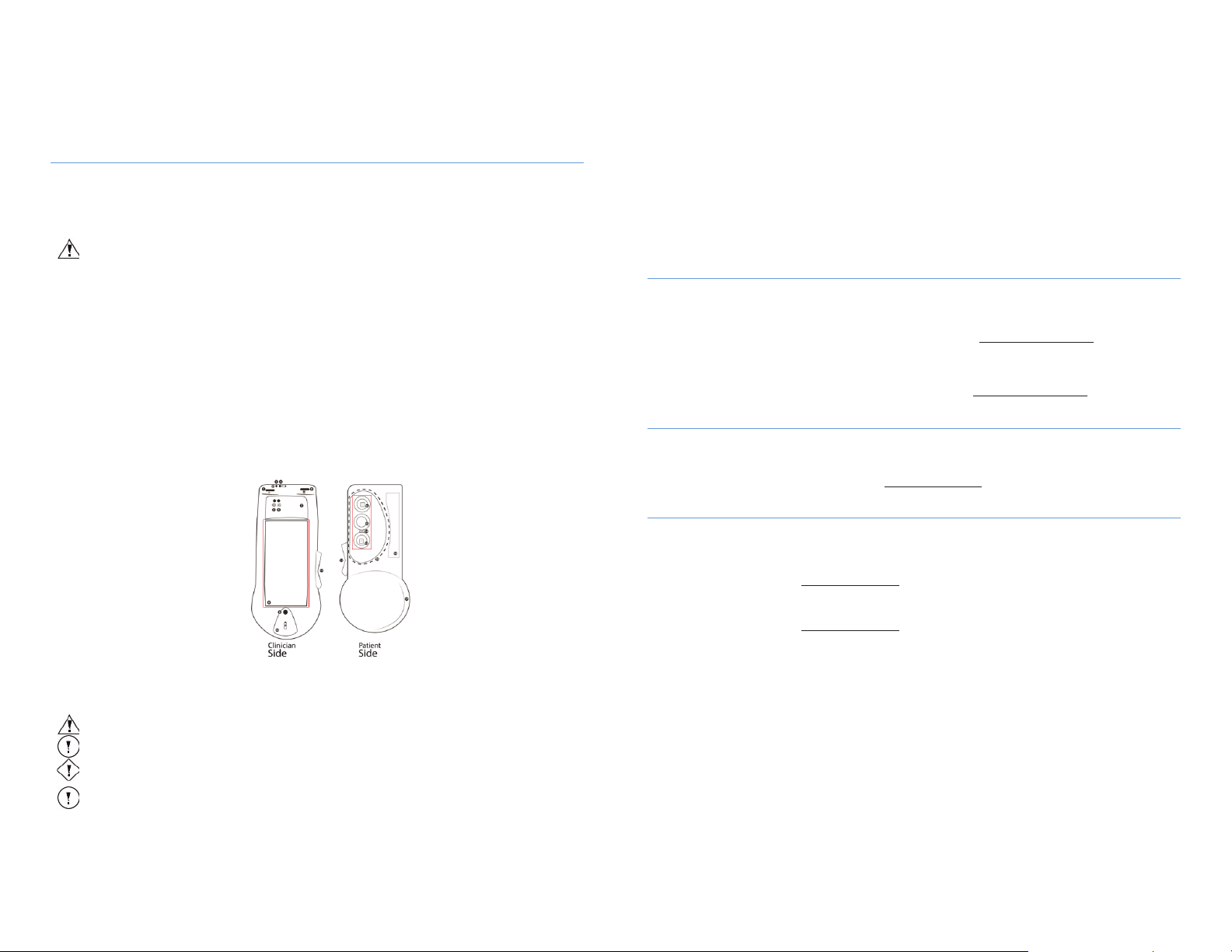
Warning
Do not reuse
Warning
Do not soak or immerse MolecuLight
i:X in water.
Prior to cleaning optical
components, ensure surfaces are disinfected as described in Section 12.2.
Caution
Improper cleaning/disinfection may
result in distorted images.
The user should dispose of the cleaning and disinfection materials as well as MolecuLight DarkDrape (if
used)
according to the biohazard waste control processes at their Institution.
12 Cleaning and Disinfecting MolecuLight ii:X
Clean and disinfect MolecuLight i:X before and after it is used and between wound assessment procedures. Failure to do so
may result in cross-contamination, and patient or user exposure to bacterial contamination. MolecuLight recommends
using CaviWipes as disinfecting wipes for cleaning and disinfecting (See Table 7 for ordering information).
The MolecuLight DarkDrape is for single use only and must not be used more than once. The MolecuLight Adapter can be
reused after being appropriately cleaned and disinfected.
the MolecuLight DarkDrape. It is a single use only accessory.
12.1 Pre-Clean the MolecuLight i:X
Wear impervious gloves such as latex gloves when handling disinfecting wipes. Use a disinfecting wipe (CaviWipe) to
remove all debris from the MolecuLight i:X by gently wiping ALL SIDES and surfaces (see Figure 2), including the Display
Screen and optical components identified within the red perimeters in Figure 26.
12.2 Disinfect the MolecuLight i:X
Use another disinfecting wipe (CaviWipe) to thoroughly wet ALL SIDES and surfaces (see Figure 2) of the MolecuLight i:X,
including the Display Screen and optical components identified within the red perimeters in Figure 26. Let the MolecuLight
i:X remain wet for 3 minutes at room temperature. Allow the MolecuLight i:X to dry.
12.3 Clean the MolecuLight i:X
Use a Lens Cleaning Towelette to thoroughly clean the Display Screen and optical components identified within the red
perimeters in Figure 26. There should be no visible debris, fingerprints or material on the Display Screen or any of the
optical components after cleaning. Allow the MolecuLight i:X to dry.
The MolecuLight i:X is now clean, disinfected and ready for use.
Figure 26: Image showing optical components (red) on Clinician Side and Patient Side of MolecuLight i:X
On the Patient Side, red perimeter includes: Optical window for Violet Wavelength LED, Camera Sensor Window, Range Finder &
Note
Note
TM
MolecuLight i:X
User Manual Revision 1.1 Page 37 of 43
On the Clinician Side, red perimeter indicat es location of the Display Screen.
Ambient Light Sensor (listed from top to bottom as depicted)
12.4 Pre-Clean the MolecuLight Adapter
Use a disinfecting wipe (CaviWipe) to remove all debris from the MolecuLight Adapter by gently wiping all sides and
surfaces, including tabs.
12.5 Disinfect the MolecuLight Adapter
Use another disinfecting (CaviWipe) wipe to thoroughly wet ALL SIDES, surfaces and tabs of the MolecuLight Adapter. Let
the MolecuLight Adapter remain wet for 3 minutes at room temperature. Allow the MolecuLight Adapter to dry. The
MolecuLight Adapter is now clean, disinfected and ready to use.
13 Maintenance of MolecuLight ii:X
MolecuLight i:X periodically executes a self-diagnosis to ensure it is operating properly, without requiring user input. The
System Status LED indicates the overall operational state of the MolecuLight i:X Imaging Device.
If the System Status LED turns to amber or red (green is the indication that the device is functioning as intended), you may
need to send the device to MolecuLight for servicing. Contact MolecuLight at [email protected].
Otherwise, except for regular cleaning (Section 12), there are no maintenance or calibration activities that need to be
performed.
For more information and details on service pricing, contact MolecuLight at [email protected].
14 Disposal of MolecuLight i:X
Comply with your country’s legal requirements for the disposal of electrical and electronic waste to dispose of the
MolecuLight i:X. The two rechargeable lithium ion batteries that power the MolecuLight i:X must be recycled appropriately
by following your country’s disposal regulations. For more information about recycling MolecuLight products, please
contact your local recycling program or MolecuLight at [email protected].
15 Troubleshooting and Support
15.1 Frequently Asked Questions
About who to contact:
1. Where do I call/email with questions?
x Contact MolecuLight at [email protected] or call +1-647-362-4684 or 1-877-818-4360 (North America
Only).
2. How can I purchase a device?
x Contact MolecuLight at [email protected] or call +1-647-362-4684 or 1-877-818-4360 (North America
About imaging bacteria:
About acquiring images:
MolecuLight i:X
Only).
3. How does the device detect bacteria?
x The device illuminates wounds with a narrow band of violet light that causes bacteria commonly found in and
around wounds to fluoresce based on the presence of endogenous molecules called fluorophores (e.g.
porphyrins, pyoverdine, etc.). Refer to Section 4.2 for additional information.
4. Which type of bacteria can be detected?
x Evidence from clinical studies indicates the MolecuLight i:X can reliably detect the following bacteria species
that are relevant for clinical wound care: Staphylocccus aureus, MRSA, Pseudomonas aeruginosa, Escherichia
coli, Coagulase-negative staphylococci, Enterococcus spp, Proteus spp, Klebsiella pneumonia, Beta-hemolytic
streptococci (Group B) and Enterobacter spp.
5. How long does it take to get an image?
TM
User Manual Revision 1.1 Page 38 of 43
Page 20

x Images appear immediately. ST-images and FL-images are captured instantly from a wound and displayed in
real-time on the device’s Display Screen and when the ‘CAPTURE IMAGE’ button is pressed.
6. How can I access the images/videos?
x Images/Videos are located in the Camera Roll and Albums. Refer to Section 9.4 for additional information.
x You can transfer these images/videos from your device to any computer using the white connecting cable on
the MolecuLight Power Cable (P/N 1142). Refer to Section 9.9 for instructions.
About operating the MolecuLight i:X:
7. Does the device require any consumables to obtain FL-Images?
x Consumables are not required for operation of the device in optimal lighting conditions.
x If you are unable to obtain optimal ambient light for Fluorescence Imaging Mode, MolecuLight recommends
using MolecuLight DarkDrape (used in conjunction with MolecuLight Adapter). For more information, refer to
Section 4.3, or contact MolecuLight at [email protected] or +1-647-362-4684 or 1-877-818-4360 (North
America Only).
8. Who is qualified to use the device?
x Trained health care professionals in wound care.
9. How do I clean the device?
x The MolecuLight i:X can be wiped clean using disinfecting wipes. Ensure excess fluid from the wipes does not
enter any openings and that the device is thoroughly dry before use. A lens towelette to clean the optical
components and Display Screen should also be used. For further information, please see Sections 3 and 12.
10. How do I take care of the device?
x MolecuLight i:X is an optical imaging device and must be handled with care at all times.
i. Do not drop, knock or shake the device. Ensure there is no dirt, moisture or scratches over the camera
sensor window, LEDs and Display Screen.
ii. Do not immerse the device in liquid.
iii. Place the MolecuLight i:X with its screen facing up on a clean, dry, flat surface when not in use.
11. Is the device safe with laser light exposure and violet light illumination?
x Yes, the device is classified in Risk Group 1 and the laser is Class 1 meaning there is not sufficient energy
produced to damage skin or eyes in normal use. It is advised to not point the device towards the eyes.
12. How do I turn on the device?
x There are 2 dark gray power buttons to turn the device on. Press and hold each for 3 seconds to turn on the
device and the Display Screen respectively.
13. Why is the Display Screen off?
x The Display Screen is turned on via the Display Screen Power Button. Push this button to turn on the Display
Screen. If it does not turn on, the Display Screen battery may need to be charged via the charging port located
below the Home Button using the white connecting cable on the MolecuLight Power Cable (P/N 1142).
x The Display Screen could also be locked. Press and release the Display Screen Power Button or the Home Button
to reveal the screen.
14. Why can’t I see red fluorescence on the screen?
x There may not be any red fluorescence signal generated by the target you are imaging.
x Ensure that the System Status LED is green, which indicates that the device optics and electronics are
functioning properly. For further information, contact [email protected].
x The Rocker Switch may be set to imaging in Standard Imaging Mode.
15. What is the System Status LED?
x This LED informs you that the device electronics and optics are functioning as designed. This LED should be
green. If the color changes to amber or red, contact MolecuLight as soon as possible. Refer to Section 6.1.1.1.
16. What does the Battery Status LED indicate?
TM
MolecuLight i:X
User Manual Revision 1.1 Page 39 of 43
x This LED indicates the battery power of the device (for the optics and electronics) and is green when the charge
is >80%. Note that there is also a battery status for the Display Screen itself in the top right corner of the screen
that is independent of the device.
17. What does the Range Finder LED indicate?
x The Range Finder notifies you when the optimal distance between the device and the wound is reached, i.e. 8-
12 cm. This is critical to follow in FL-Mode and it is also advised to observe the Range Finder LED when in STMode so that the images obtained will have a similar field of view.
18. How do I check if the Range Finder is working properly?
x You can use a ruler at various distances from the device to verify the Range Finder LED Status. At a 5 cm
distance, the LED should be amber, at 10 cm, the LED should turn green and at 15 cm the LED should turn
amber again. If the results are incorrect, do not use the device and contact MolecuLight at
[email protected] or call +1-647-362-4684 or 1-877-818-4360 (North America Only).
19. What does the Ambient Light Status LED indicate?
x For optimal image quality in FL-Mode, it is important that the lighting conditions are in a dark environment. The
Ambient Light Status LED will notify you when conditions are optimal (the LED will be green).
20. How do I check if the Ambient Light Status LED is working?
x The Ambient Light Status LED should be amber in a bright environment and turn green in a dark environment.
Make sure all lighting is off in order for the LED to turn green. If you have any questions, contact MolecuLight at
[email protected] or call +1-647-362-4684 or 1-877-818-4360 (North America Only).
21. The Ambient Light Status LED turns off when the device is in FL-Mode. Is this intended?
x Yes, this is the normal operation. The ambient light sensor which is used to measure the ambient light
conditions is also sensitive to the light emitted from the device during FL-Mode operation, therefore the
indicator LED turns off in this mode to ensure it does not provide a false reading. The lighting conditions should
be adjusted such that the Ambient Light Status LED is green prior to using FL-Mode.
x If you are unable to obtain optimal ambient light for FL-Mode, MolecuLight recommends using MolecuLight
DarkDrape (used in conjunction with MolecuLight Adapter). For more information, refer to Section 4.3, or
contact MolecuLight at [email protected] or +1-647-362-4684 or 1-877-818-4360 (North America Only).
22. How do I know that my Device is working properly?
x The System Status LED indicates the functionality of the electronics and optics of the device. This LED is green
when the device is turned on and operating properly. If it is amber or red, contact MolecuLight at
[email protected].
23. How long does it take to charge the device?
x The device charges to approximately 80% of its total capacity after 2 hours of charging and will be fully charged
after approximately 5 hours.
About operating the wound measurement app:
24. Why do I need to use the MolecuLight WoundStickers?
x In the absence of MolecuLight WoundStickers, no area measurement is provided. The use of 2 MolecuLight
WoundSticker may produce an average wound measurement (area and/or dimension) error of 5%, when the
image is taken with MolecuLight WoundStickers in the plane of the wound. The use of only 1 MolecuLight
WoundSticker may produce an average wound measurement (area and/or dimension) error of 15%.
TM
MolecuLight i:X
User Manual Revision 1.1 Page 40 of 43
Page 21
iX Camera App Error
Message
Action
“iX Camera” Would
Like to Access the
Camera
<Don’t Allow>
<OK>
Message from iOS to
confirm the user is
granting the A
pp access
to
the camera hardware to
allow capture of images
and video.
This message appears the first time the
A
<OK> this setting will be saved and the
message will no longer appear.
“iX Camera” Would
Like to Access Your
Photos
<Don’t Allow>
<OK>
Message from iOS to
confirm the user is
granting the A
pp access
to
the
Image L
ibrary to view
and store images and
video.
This message appears the first time the
A
Li
Once the user selects <OK> this
setting will be saved and the message
will no longer appear.
Camera Access Not
Enabled
iOS has detected that
access to the
hardware has been
disabled by the user.
This message can be caused by the user
either selecting <Don’t Allow> when it
was prompted to give access to the
camera or the user manually changed
the settings in the “Settings
|
Camera” menu.
Go t
o “Settings | Privacy |
Camera”
and locate the toggle switch for the
iX Camera and swipe to the enable
position.
Image Library Access
Not Enabled
iOS has detected that
access to the
Library has been disabled
by the user.
This message can be caused by the user
either selecting <Don’t Allow> when it
was prompted to give access to the
Image Library
changed the settings in the “Settings |
Privacy | Photos” menu.
Go to “Setting
s | Privacy |
Photos”
and locate the toggle switch for the
iX Camera and swipe to the enable
position.
Video Maximum
Recording Reached
This message notifies the
user that video is no
longer being captured due
to reaching the 30 second
timeout limit.
has been saved.
The maximum recording duration of 30
seconds has been reached.
Video has been saved, no action
required if user was finished
recording video.
If not finished, the
user can Press “START RECORDING”
again to start recording a new
video.
Allow “iX Camera” to
delete this photo?
<Don’t Allow>
<Delete>
iOS has detected that the
user has selected to delete
an image.
This message appears when the user
selects the “Trash” icon while viewing
an image.
User can select <Don’t Allow> to
return to browsing without
deleting, or <Delete> to delete the
image from the Image Library.
Allow “iX Camera” to
delete this video?
<Don’t Allow>
<Delete>
iOS has detected that the
user has selected to delete
a video.
This message appears when the user
selects the “Trash” icon while viewing a
video.
User can select <Don’t Allow> to
return to browsing without
deleting, or <Delete> to delete the
video from the Image Library.
Caution
Any
evidence of tampering or disassembly shall void this warranty.
Caution
Any evidence of
damage (crack, discoloration) shall void this warranty.
15.2 iX Camera App Troubleshooting
Description Cause
pp is opened. Once the user selects
pp is accessing the Image
brary.
Select <OK>
Select <OK>
16 Warranty
MolecuLight warrants this product to be free from any defects in material and workmanship for a period of one year from
the date of purchase by the initial purchaser.
Contact MolecuLight at [email protected] to report any defects and obtain a returned material authorization
(RMA) number and shipping instructions prior to returning the device to MolecuLight.
All shipping charges and duties for returned goods are the responsibility of the purchaser.
Upon inspection and evaluation of the returned unit by MolecuLight, your MolecuLight i:X Imaging Device will either be
replaced or repaired (during the warranty period).
camera
Image
The video
or the user manually
Table 14: iX Camera App error messages
| Privacy
If you are having any difficulty with your MolecuLight i:X or have any questions that require troubleshooting, contact
MolecuLight at [email protected]. A representative will respond to your inquiry. If you have any questions about
operating the device, contact MolecuLight:
MolecuLight Inc.
425 University Ave., Suite 700
Toronto, Ontario, Canada
M5G 1T6
Telephone: +1-647-362-4684 or 1-877-818-4360 (North America Only)
[email protected]
www.moleculight.com
TM
MolecuLight i:X
User Manual Revision 1.1 Page 41 of 43
MolecuLight i:X
TM
User Manual Revision 1.1 Page 42 of 43
Page 22
Specification
Value
Temperature
10 0C to 30 0C
Relative humidity
10-70%
Atmospheric pressure
89-102 kPa
Specification
Value
Temperature
-10 0C to 50 0C
Relative humidity
10-70%
Atmospheric pressure
89-102 kPa
Dimension
Value
Height
21 cm
Width (maximum)
9.5 cm
Depth (maximum)
4 cm
Weight
398 g
Model: PSA05F-050QAL6
Input
Output
100-240 V
5 V
0.18 A
1 A
60 Hz
Model: PSA10F-050
Input
Output
100-240 V
5 V
0.35 A
2 A
60 Hz
Appendix A: Specifications
The device was tested to the following specifications:
x Safety Testing per IEC 60601-1:2005+A1:2012 / EN 60601-1:2006+A1:2013
including Canadian National Differences per CAN/CSA-C22.2 No. 60601-1:14 and
US National Differences per ANSI/AAMI ES 60601-1:2005/A1:2012
x Safety EMC Testing per IEC 60601-1-2:2014 4th Edition / EN 60601-1-2:2015
x Safety LED testing per IEC 60601-2-57:2011 and IEC 62471:2006 / EN 60601-2-57:2011 and EN 62471:2008
x Usability Testing per IEC 60601-1-6:2010+A1:2013 / EN 60601-1-6:2010 and EN 62366:2008
x Risk Management per ISO 14971:2007 / EN ISO 14971:2012
x Quality Management System Requirements per ISO 13485:2016 / EN ISO 13485:2016
Specifications for MolecuLight i:X operating conditions:
Specifications for MolecuLight i:X transportation and storage conditions:
MolecuLight i:X dimensions:
The electrical specifications for the MolecuLight Power Cable P/N 1142 are as follows:
MolecuLight i:X
TM
User Manual Revision 1.1 Page 43 of 43
Page 23
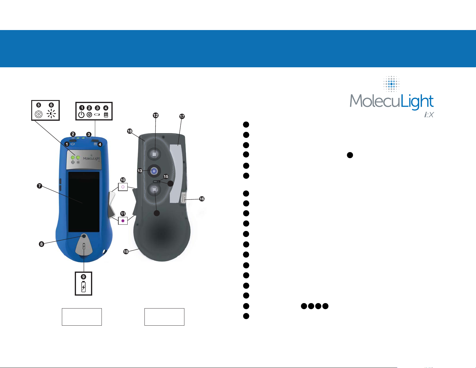
APPENDIX B: DEVICE OVERVIEW
1.
14
12
OVERVIEW
Power Button: turns device ON/OFF by pressing and holding 3 seconds
1
System Status LED: indicates overall Device performance (Green is required)
2
Battery Status LED: indicates Device battery charge (Green or Amber is required for image capture)
3
4
Display Screen power button: turns Display Screen ON/OFF by pressing and holding 3 seconds
Range Finder LED: indicates optimal distance of device from wound (Green is required for image capture)
5
6
Ambient Light Status LED: indicates optimal lighting environment for fluorescence imaging (Green is required for
Fluorescence Imaging Mode™)
Display Screen: provides touch functionality and displays images/videos
7
8
Home Button: turns Display Screen ON
9
Port for charging Display Screen and downloading data: to be used with MolecuLight i:X Connecting Cable
10
Rocker Switch in Standard Imaging Mode™ position: allows for Standard Mode Imaging
11
Rocker Switch in Fluorescence Imaging Mode™ position: allows for Fluorescence Mode Imaging
12
Violet wavelength LEDs: provide illumination when in Fluorescence Imaging Mode™
7
FRONT BACK
Camera Sensor Window: protects the camera sensor which allows image and video capture
13
Range Finder Sensor: detects optimal distance from wound
14
15
Ambient Light Sensor: detects ambient lighting conditions
MolecuLight i:X Charging Port: allows charging of device with MolecuLight Power Cable
16
Label: lists certifications, references instructions
17
18
Illumination zone contains:
19
Holding Contour: allows proper positioning of hands
12 13 14 15 Fingers should be kept out of this area
Page 24
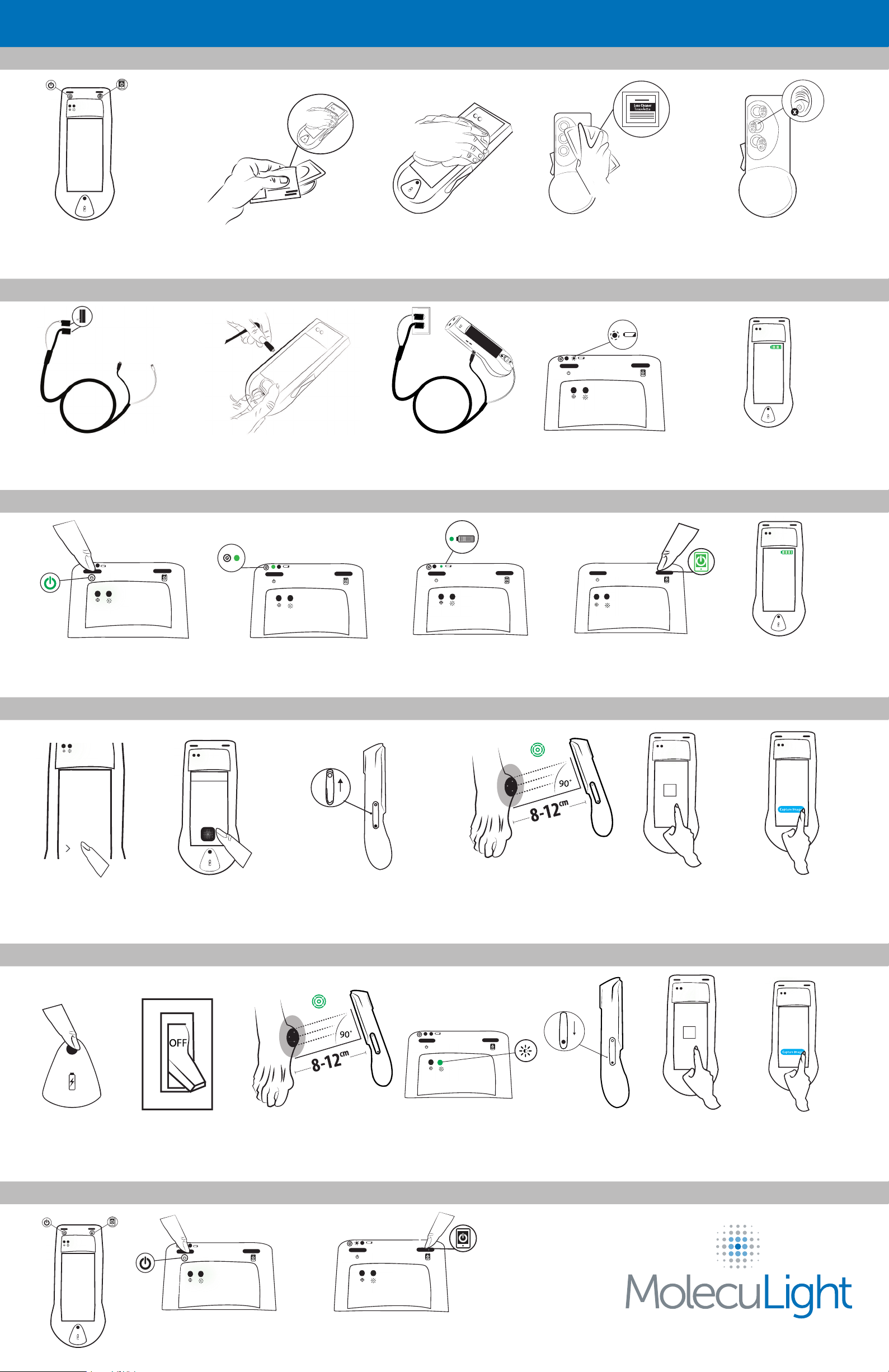
APPENDIX C: MolecuLight i:X™ QUICK START GUIDE
1. CLEANING
a. Ensure i:X is OFF or turn
device OFF and Display Screen
OFF.
2. CHARGING
a. Charge device and Display
Screen with the MolecuLight
Power Cable.
3. TURNING ON
b. Use a disinfecting wipe to
preclean the i:X.
b. One end of the Power Cable
connects to the device and the
other to the Display Screen.
c. Use a second disinfecting
wipe to clean the whole device
including all crevices.
c. Both charging ends should
be plugged into wall connector.
d. Use lens towelette to clean
all glass surfaces.
d. LED ashes when device is
being charged.
e. Check that all windows are
clean, free of all debris
and ngerprints.
e. Battery icon will be visible
when Display Screen is
being charged.
a. Push power button (3 sec) to
turn device on.
b. Check that the System Status
LED will be green (if yellow or red
consult User Manual).
4. CAPTURING A STANDARD LIGHT IMAGE/VIDEO
Slide to unlock
a. Press the home
button and select
slider.
b. Select the iX Camera App
on Display Screen.
c. Position Rocker Switch in
Up position.
5. CAPTURING A FLUORESCENCE LIGHT IMAGE/VIDEO
c. Verify the battery status on
device (green indicates
maximum charge capacity),
d. Use Range Finder Sensor
LED to reach appropriate
distance (LED turns green).
d. Push screen power
button (3 sec) to turn
Display Screen on.
e. Tap on the screen
to improve focus
as required.
e. Verify Display Screen
battery capacity.
f. Capture image
and/or video, Range
Finder Sensor LED
should remain green.
a. Use home button
to access screen,
select slider
if needed.
6. TURNING OFF
b.Turn off room lights.
a. Turn device off by pressing
power button for 3 seconds.
c. Use Range Finder Sensor
LED to reach appropriate
distance (LED turns green).
d. Conrm Ambient Light
Sensor LED is green
before toggling Rocker
Switch to FL-Mode.
b. Turn Display Screen off by
pressing screen power button
for 3 seconds.
e. Toggle to FL-Mode;
Ambient Light Sensor
LED turns off when
FL-Mode is activated.
f. Tap on the screen
to improve focus
if required.
©2017 MolecuLight Inc. All Rights Reserved. PN 1295 Rev 1.0 .
Consult the MolecuLight i:X™ User Manual for more information.
g. Capture image
and/or video, Range
Finder Sensor LED
should remain green.
Page 25
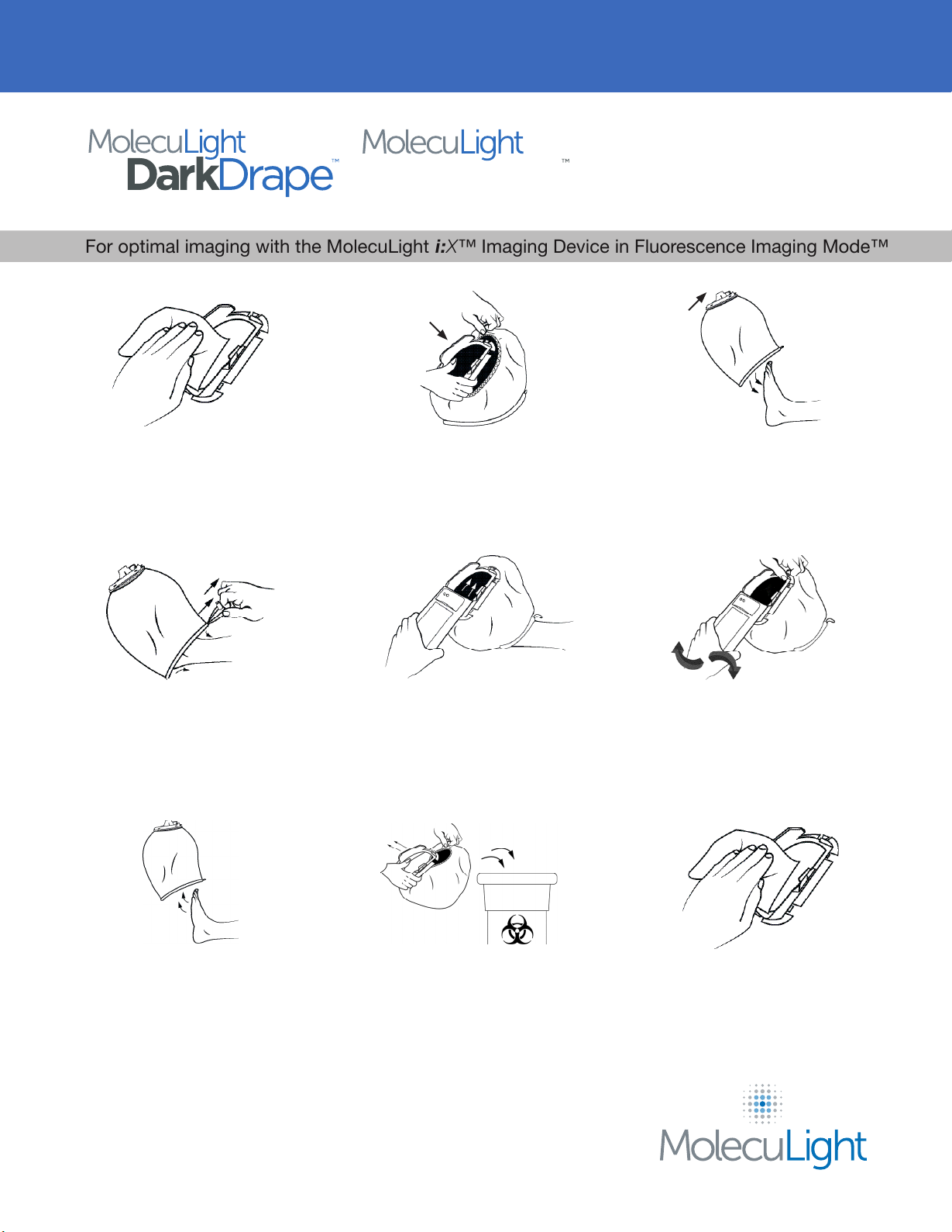
APPENDIX D: INSTRUCTIONS FOR USE
Adapter
For optimal imaging with the MolecuLight i:X™ Imaging Device in Fluorescence Imaging Mode™
1. Use a disinfecting wipe to clean
the MolecuLight Adapter.
4. Secure the MolecuLight
DarkDrape by pulling on the draw
string and locking it in place with
the push button. Avoid touching
the patient’s wound with the
DarkDrape.
Top
2. Expand the MolecuLight
DarkDrape into a balloon shape
and attach it to the MolecuLight
Adapter by securing it in between
the 5 tabs.
5. Slide the MolecuLight i:X
Imaging Device over the
MolecuLight Adapter until the
device clicks into place. Avoid
touching the patient’s wound with
the DarkDrape.
Top
3. Carefully place the MolecuLight
DarkDrape over the patient’s foot.
Avoid touching the wound with
the MolecuLight DarkDrape. Keep
orientation of the MolecuLight
Adapter as shown in Step 2.
6. When imaging is complete, hold
the MolecuLight Adapter tab to
remove the MolecuLight i:X.
7. Press the push button to loosen
the draw string. Carefully remove
the MolecuLight DarkDrape from
the patient’s foot. Avoid touching
the wound with the DarkDrape.
The MolecuLight DarkDrape and MolecuLight Adapter provide a convenient and
optimal environment for imaging wounds with the MolecuLight i:X Imaging Device
in Fluorescence Imaging Mode when room lights cannot be turned o.
The MolecuLight DarkDrape is for single use only.
8. Remove the MolecuLight
Adapter from the MolecuLight
DarkDrape. The MolecuLight
Adapter can be disinfected and
reused. Dispose of the
MolecuLight DarkDrape according
to your institutional guidelines.
9. Use a disinfecting wipe to clean
the MolecuLight Adapter.
©2017 MolecuLight Inc. All Rights Reserved. PN 1297 Rev 1.0 .
Consult the MolecuLight i:X™ User Manual for more information.
Page 26
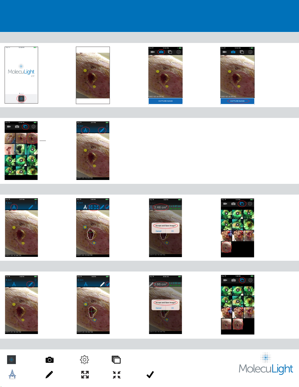
APPENDIX E: WOUND MEASUREMENT QUICK START GUIDE
CAPTURE IMAGE
Open the iX Camera App.
ACCESS IMAGE
To view the images within
your Active Album, select
the ‘Image Library’ icon.
Note: There may be a
slight delay before the
images appear.
Use your index nger or
a stylus to scroll through
the images and select the
image of interest.
Newly acquired images and
newly saved images appear
at the bottom of the
Active Album.
AUTO MODE: To Automatically Trace Wound Border
Select the ‘Auto Trace’
icon.
Place two MolecuLight
Wound Stickers in the
plane of the wound.
When holding the device
in a portrait (vertical)
orientation, ensure the
MolecuLight Wound
Sticker placement is such
that the stickers appear at
the top and bottom of the
Display Screen as depicted.
The image selected will
appear on the screen.
The Auto Trace and
Manual Trace icons
become available.
Auto Trace automatically
draws a white border
around the wound. The
MolecuLight Wound
Stickers will be outlined
in blue.
Use the ‘Expand’ or
‘Contract’ icons to adjust
the wound border if
necessary.
Select the ‘Checkmark’
icon to accept the
wound border.
Select the ‘Camera’ icon
to capture images in
Standard Imaging Mode.
The wound area
measurement is displayed.
An ‘Accept and Save
Image?’ prompt will
appear.
Select ‘OK’ to save the
image with the overlaid
wound border trace and
measurement to the
Image Library.
Select ‘Cancel’ to reject
the reported wound area
and return to the wound
border trace.
Use the Range Finder LED
to position the MolecuLight
i:X™ at the correct distance
from the wound.
Ensure the MolecuLight i:X
Camera Sensor is parallel
to the wound and the
MolecuLight Wound
Stickers are in eld of view.
Select ‘CAPTURE IMAGE’
Select the ‘Image Library’
icon to browse the Camera
Roll/Active Album for
images saved with area
measurements.
Newly acquired images
and newly saved images
appear at the bottom of the
Active Album.
MANUAL MODE: To Manually Trace Wound Border
Select the ‘Manual Trace’
icon.
ICON LEGEND
iX Camera App
Auto Trace
Camera
Manual Trace Expand Contract Checkmark
Settings
Trace a wound border
with your index nger or a
stylus. The MolecuLight
Wound Stickers will be
outlined in blue.
Once the trace is complete,
select the ‘Checkmark’
icon to accept the
wound border.
Image Library
The wound area
measurement is displayed.
An ‘Accept and Save
Image?’ prompt will
appear.
Select ‘OK’ to save the
image with the overlaid
wound border trace and
measurement to the
Image Library.
Select ‘Cancel’ to reject
the reported wound area
and return to the wound
border trace.
Consult the MolecuLight i:X™ User Manual for more information.
Select the ‘Image Library’
icon to browse the Camera
Roll/Active Album for
images saved with area
measurements.
Newly acquired images
and newly saved images
appear at the bottom of the
Active Album.
©2017 MolecuLight Inc. All Rights Reserved. PN 1317 Rev 1.0.
 Loading...