

Page 1

VERSAmax
™
Tunable Microplate Reader
Operator’s Manual
for Instruments with Serial Numbers
Beginning with BN
Molecular Devices Corporation
1311 Orleans Drive
Sunnyvale, California 94089
Part # 0112-0084
Rev. A
Page 2

Molecular Devices Corporation
VERSAmax
™
Operator’s Manual
Copyright
Copyright 2001, Molecular Devices Corporation. All rights reserved. No part of this publication may
be reproduced, transmitted, transcribed, stored in a retrieval system, or translated into any language
or computer language, in any form or by any means, electronic, mechanical, magnetic, optical, chemical, manual, or otherwise, without the prior written permission of Molecular Devices Corporation,
1311 Orleans Drive, Sunnyvale, California, 94089, United States of America.
Patents
The VERSAmax and methods are protected by the following patents:
U.S. Patents
4,968,148, 5,112,134,
and
6,151,111;
Canadian Patent
1,305,334
.
Other U.S. and International patents pending.
Trademarks
VERSAmax and Automix are trademarks and SOFTmax is a registered trademark of Molecular
Devices Corporation.
Apple and Macintosh are registered trademarks of Apple Computer, Incorporated.
All other company and product names are trademarks or registered trademarks of their respective
owners.
Disclaimer
Molecular Devices Corporation reserves the right to change its products and services at any time to
incorporate technological developments. This manual is subject to change without notice.
Although this manual has been prepared with every precaution to ensure accuracy, Molecular Devices
Corporation assumes no liability for any errors or omissions, nor for any damages resulting from the
application or use of this information.
Molecular Devices Corporation Instrument Warranty
Molecular Devices Corporation warrants this product against defects in material or workmanship as
follows:
1) All parts of the VERSAmax Tunable Microplate Reader are warranted for a period of one (1) year
from the original date of delivery.
2) All labor charges to repair the product for a period of one (1) year from the original date of
delivery will be paid by Molecular Devices Corporation.
3) This warranty covers the VERSAmax instrument only, and does not extend to any computer,
printer, software, reagents, or disposables used with the instrument.
ii VERSAmax Tunable Microplate Reader Operator’s Manual
Page 3
Labor and Parts
To obtain warranty service during the applicable warranty period, you must take the product or deliver the product properly packaged in the original shipping materials and carton to an authorized
Molecular Devices Corporation service facility. You must call or write to the nearest Molecular
Devices Corporation service facility to schedule warranty service. You may call Molecular Devices
Corporation at the telephone number or address below to locate the nearest service facility. You must
schedule warranty service
questing warranty service, you must present proof of purchase documentation which includes the
date of purchase, and Molecular Devices Corporation must have the enclosed Warranty Registration
form completed, signed and returned by you within ten (10) working days of the date of delivery.
This warranty covers only defects arising under normal usage and does not cover malfunctions or failures resulting from misuse, abuse, neglect, alteration, modification, or repairs by other than an authorized Molecular Devices Corporation service facility.
Repair or replacement as provided under this warranty is the exclusive remedy of the purchaser (the
“Buyer”).
sequential damages for breach of any express or implied warranty on this product, except to the extent required by applicable law. The Seller specifically excludes all express and implied warranties
including without limitation any implied warranty that the products sold under this agreement are
merchantable or are fit for any particular purpose, except such warranties expressly identified as
warranties and set forth in the Seller’s current operating manual, catalog or written guarantee covering such product. The Seller also makes no warranty that the products sold under this agreement
are delivered free of the rightful claim of any third party by way of patent infringement or the like.
If the Buyer furnishes specifications to the Seller, the Buyer agrees to hold the Seller harmless against
any claim which arises out of compliance with the specifications.
Molecular Devices Corporation (the “Seller”) shall not be liable for any incidental or con-
prior to bringing or shipping the product for servicing. At the time of re-
Any description of the products contained in this agreement is for the sole purpose of identifying
them. Any such description is not part of the basis of the bargain and does not constitute a warranty
that the products shall conform to that description. Any sample or model used in connection with this
agreement is for illustrative purposes only, is not part of the basis of the bargain, and is not to be construed as a warranty that the products will conform to the sample or model. No affirmation of fact or
promise made by the Seller, whether or not in this agreement, shall constitute a warranty that the
products will conform to the affirmation or the promise.
For the name of the nearest authorized Molecular Devices Corporation service facility, please contact
Molecular Devices at one of the following telephone numbers:
(408) 747-1700
(800) 635-5577 (U.S. and California)
VERSA
MAX
Tunable Microplate Reader
100-240V ~ 4A 50-60 HZ T4.0A
!
2 Lines Fused, unplug before servicing!
Vor Wartungsarbeiten Netzstecker ziehen!
Sunnyvale, CA!
Made in USA
Protected by US Patents 4,968,148; 5,112,134;
and 6,151,111
Protected by Canadian Patent 1,305,334
Other US and International patents pending
VERSAmax Tunable Microplate Reader Operator’s Manual iii
Page 4

Contents
Figures and Table . . . . . . . . . . . . . . . . . . . . . . . . . . . . . . . . . . vi
Conventions Used in this Manual . . . . . . . . . . . . . . . . . . . . vii
Glossary of Terms. . . . . . . . . . . . . . . . . . . . . . . . . . . . . . . . . .vii
Chapter 1 Instrument Description. . . . . . . . . . . . . . . . . . . . . . . . . 1-1
Introduction. . . . . . . . . . . . . . . . . . . . . . . . . . . . . . . . . . . . . . 1-3
General Overview . . . . . . . . . . . . . . . . . . . . . . . . . . 1-3
Component Description . . . . . . . . . . . . . . . . . . . . . . . . . . . 1-4
Control Panel . . . . . . . . . . . . . . . . . . . . . . . . . . . . . . 1-4
Control Panel Display. . . . . . . . . . . . . . . . . . . . . . . 1-5
The Microplate Drawer . . . . . . . . . . . . . . . . . . . . . 1-6
The Back Panel. . . . . . . . . . . . . . . . . . . . . . . . . . . . . 1-7
Functional Description. . . . . . . . . . . . . . . . . . . . . . . . . . . . . 1-8
Stand-Alone Operation . . . . . . . . . . . . . . . . . . . . . 1-8
Computer Control. . . . . . . . . . . . . . . . . . . . . . . . . . 1-9
Specifications. . . . . . . . . . . . . . . . . . . . . . . . . . . . . . . . . . . . 1-11
Chapter 2 Installation. . . . . . . . . . . . . . . . . . . . . . . . . . . . . . . . . . . . 2-1
Installation Warnings. . . . . . . . . . . . . . . . . . . . . . . . . . . . . . 2-3
Installation Cautions . . . . . . . . . . . . . . . . . . . . . . . . . . . . . . 2-3
Unpacking . . . . . . . . . . . . . . . . . . . . . . . . . . . . . . . . . . . . . . . 2-3
Setting Up for Stand-Alone Use . . . . . . . . . . . . . . . . . . . . . 2-4
Chapter 3 Stand-Alone Operation. . . . . . . . . . . . . . . . . . . . . . . . . 3-1
Prepare for a Reading . . . . . . . . . . . . . . . . . . . . . . . . . . . . . 3-3
Turn the Instrument and Printer On . . . . . . . . . . 3-3
Set the Temperature . . . . . . . . . . . . . . . . . . . . . . . . 3-3
iv VERSAmax Tunable Microplate Reader Operator’s Manual
Page 5

Chapter 4 Maintenance and Troubleshooting . . . . . . . . . . . . . . 4-1
Technical Support. . . . . . . . . . . . . . . . . . . . . . . . . . . . . . . . . 4-3
Warnings and Cautions . . . . . . . . . . . . . . . . . . . . . . . . . . . . 4-3
General . . . . . . . . . . . . . . . . . . . . . . . . . . . . . . . . . . . . . . . . . . 4-4
Cleaning . . . . . . . . . . . . . . . . . . . . . . . . . . . . . . . . . . . . . . . . . 4-4
Cleaning the Fan Filter. . . . . . . . . . . . . . . . . . . . . . . . . . . . . 4-4
Changing the Fuses . . . . . . . . . . . . . . . . . . . . . . . . . . . . . . . 4-5
Error Codes and Probable Causes . . . . . . . . . . . . . . . . . . . 4-7
Error Messages . . . . . . . . . . . . . . . . . . . . . . . . . . . . 4-7
Opening the Drawer Manually . . . . . . . . . . . . . . . . . . . . 4-11
Appendix A Printers and Cables . . . . . . . . . . . . . . . . . . . . . . . . . . . . A-1
Appendix B Accessories. . . . . . . . . . . . . . . . . . . . . . . . . . . . . . . . . . . . B-1
Index. . . . . . . . . . . . . . . . . . . . . . . . . . . . . . . . . . . . . . . . . . . . . . . . . . . . . .I-1
VERSAmax Tunable Microplate Reader Operator’s Manual v
Page 6

Figures
Table
Figure 1.1: VERSAmax . . . . . . . . . . . . . . . . . . . . . . . . . . . . . . . . . . . . . . 1-3
Figure 1.2: Major Areas of the VERSAmax . . . . . . . . . . . . . . . . . . . . . . . .1-4
Figure 1.3: Control Panel . . . . . . . . . . . . . . . . . . . . . . . . . . . . . . . . . . . . . . .1-4
Figure 1.4: Microplate Drawer . . . . . . . . . . . . . . . . . . . . . . . . . . . . . . . . . .1-6
Figure 1.5: Components on the Back Panel of the
VERSAmax . . . . . . . . . . . . . . . . . . . . . . . . . . . . . . . . . . . . . . . . .1-7
Figure 2.1: View of Rear Panel . . . . . . . . . . . . . . . . . . . . . . . . . . . . . . . . . .2-4
Figure 4.1: Power Switch, Fuse Box, and Power Receptacle. . . . . . . . . .4-5
Figure 4.2: Removing the Fuse Box . . . . . . . . . . . . . . . . . . . . . . . . . . . . . .4-6
Figure 4.3: The Fuse Box and Holder (with Fuses) Removed. . . . . . . . .4-6
Table 4.1: Error Codes. . . . . . . . . . . . . . . . . . . . . . . . . . . . . . . . . . . . . . 4-7
vi VERSAmax Tunable Microplate Reader Operator’s Manual
Page 7

Conventions
Used in this
Manual
Glossary of
Terms
The names of keys that appear on the VERSAmax control panel are shown in
boxed Helvetica type. Example:
Italic and boldface type are used for emphasis. Examples: “Press carefully to
engage,”
NOTE:
!
“Do not press down.”
A note provides information that will help you properly execute an
action or procedure.
CAUTION:
age the instrument or one of its components or could result in loss of
data.
WARNING:
person working with the system.
BIOHAZARD:
logical agents requiring that proper handling precautions be taken.
Indicates an action or condition that could potentially dam-
Indicates a situation that could result in potential injury to a
Indicates a condition involving potentially infectious bio-
[Drawer]
.
Absorbance, A
The amount of light absorbed by a solution. To measure absorbance accurately, it is necessary to eliminate light scatter. In the absence of turbidity,
absorbance = optical density.
A = log (I
= incident light
I
0
I = transmitted light
In this manual, we use the terms absorbance and optical density
interchangeably.
0
/I)
Optical Density, OD
The amount of light passing through a sample to a detector relative to the
total amount of light available. Optical Density includes absorbance of the
sample plus light scatter from turbidity.
Transmittance, T
The ratio of transmitted light to the incident light.
T = I/I
%T = 100 T
0
VERSAmax Tunable Microplate Reader Operator’s Manual vii
Page 8

viii VERSAmax Tunable Microplate Reader Operator’s Manual
Page 9

Chapter 1 Instrument Description
Introduction. . . . . . . . . . . . . . . . . . . . . . . . . . . . . . . . . . . . . . .1-3
General Overview. . . . . . . . . . . . . . . . . . . . . . . . . . .1-3
Component Description . . . . . . . . . . . . . . . . . . . . . . . . . . . .1-4
Control Panel . . . . . . . . . . . . . . . . . . . . . . . . . . . . . . .1-4
Control Panel Display . . . . . . . . . . . . . . . . . . . . . . .1-5
The Microplate Drawer . . . . . . . . . . . . . . . . . . . . . .1-6
The Back Panel. . . . . . . . . . . . . . . . . . . . . . . . . . . . . .1-7
Functional Description . . . . . . . . . . . . . . . . . . . . . . . . . . . . .1-8
Stand-Alone Operation . . . . . . . . . . . . . . . . . . . . . .1-8
Temperature Regulation . . . . . . . . . . . . . . . . . . . . .1-9
Computer Control. . . . . . . . . . . . . . . . . . . . . . . . . . .1-9
Specifications . . . . . . . . . . . . . . . . . . . . . . . . . . . . . .1-11
Page 10

Chapter 1
1-2 VERSAmax Tunable Microplate Reader Operator’s Manual
Page 11
Instrument Description
Introduction
General Overview
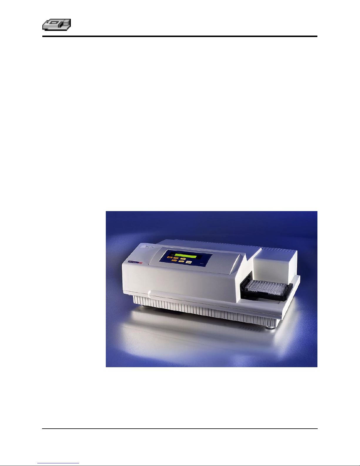
The VERSAmax™ Tunable Microplate Reader incorporates a holographic
grating monochromator which allows you to specify a precise wavelength,
from 340 nm to 850 nm, for the absorbance maximum of your sample when
controlled by an external computer and SOFTmax
VERSAmax can measure optical density (OD) for a single point in time (endpoint) or over a speciÞed period of time (kinetic).
Typical applications include endpoint assays (ELISAs, performed in microplates or as dot blots, quantitation of cytoproliferation by MTT reduction, colorimetric protein assays, and kinetic measurements (enzyme studies, such as
determination of the activity of enzymes released from cells, and kinetic ELISAs).
Standard 96-well microplates, strip wells, and Þlter-bottom microplates can
be used in the VERSAmax. The contents of the wells in a microplate can be
mixed automatically by shaking before each read cycle, which makes it possible to perform kinetic analysis of solid-phase, enzyme-mediated reactions
(mixing is not critical for liquid-phase reactions).
The temperature of the microplate chamber can be regulated, if desired from
4°C above ambient to 45°C.
®
PRO software. The
Figure 1.1: The VERSAmax Instrument
VERSAmax Tunable Microplate Reader Operator’s Manual 1-3
Page 12

Chapter 1
Component
Description
Control Panel
The main components of the VERSAmax are:
• The control panel
• The microplate drawer
• The back panel (connections and power switch)
Back Panel
Microplate
Drawer
Figure 1.2: Major areas of the VERSAmax
Control Panel
Figure 1.3: Control Panel
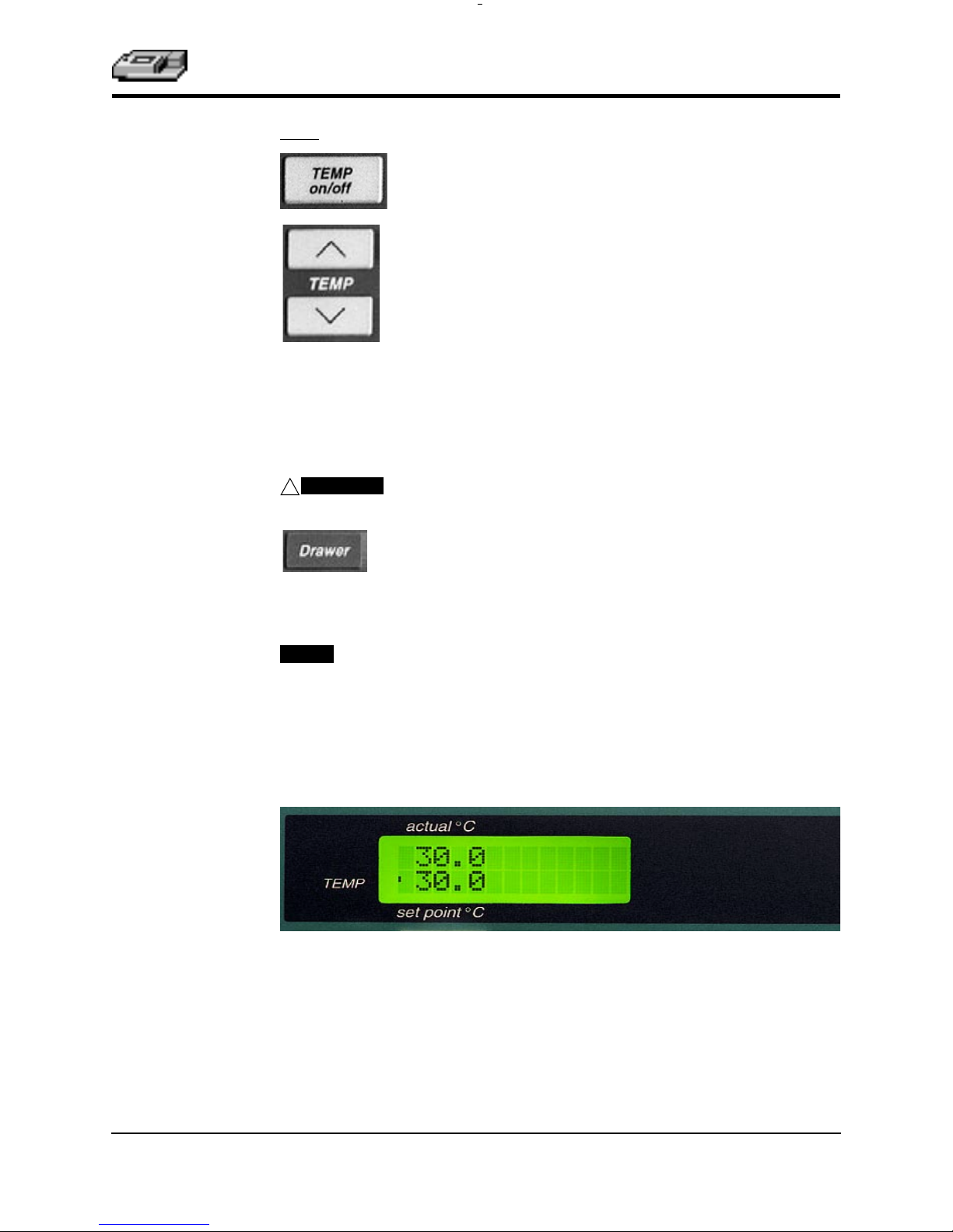
The control panel consists of an LCD and four pressure-sensitive, membrane
keys which can be used to set the temperature inside the microplate drawer
and open or close the microplate drawer. Pressing a control panel key activates the function.
LCD
A 2- × -20-character liquid crystal display which shows the current instrument
settings.
1-4 VERSAmax Tunable Microplate Reader Operator’s Manual
Page 13
Instrument Description
Keys
(Incubator) Enables/disables the incubator function.
(Incubator) Allows you to enter a set point to regulate the
microplate chamber temperature. Pressing the up or down
arrow key scrolls up or down, starting at the previous temperature setting (or the default of 37.0°C, if no setting had
been made). Pressing the up (
crements or decrements the temperature shown in the display by 0.1°C; pressing and holding
or decrements the temperature shown in the display by 1°C
until it is released. If you increment the setting to the highest
limit (45°C) and continue to press the up (
play will not change. If you decrement the setting to the lowest limit, 15°C, and continue to press the down (
display will not change.
▲
) or down (
either arrow increments
▼
) arrow once in-
▲
) arrow, the dis-
▼
) arrow, the
CAUTION:
!
NOTE:
will
If the VERSAmax is idle, all keys on the control panel are active. The
instrument will automatically close the microplate drawer for the next
reading.
If the incubator is disabled, pressing the
enable the incubator.
Opens or closes (toggles) the microplate drawer. Whether or
not the drawer will remain open depends on the incubator
setting. If the incubator is off, the drawer will remain open;
if the incubator is on, the drawer will close after approximately 10 seconds to assist in maintaining temperature control within the microplate chamber.
Control Panel Display
[Temp On/Off]
key
The left side of the display shows the temperature, both actual and set point,
and whether or not the temperature is at the set point (enunciator blinks if
not at set point).
VERSAmax Tunable Microplate Reader Operator’s Manual 1-5
Page 14
Chapter 1
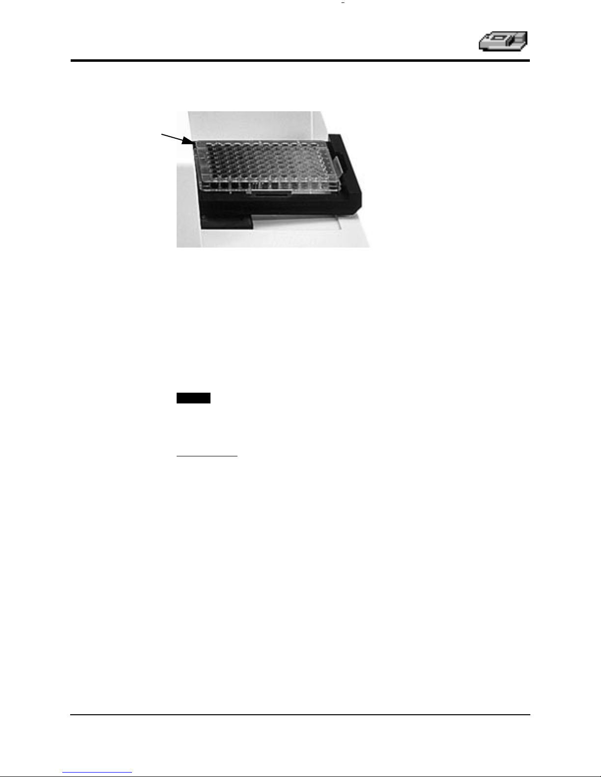
A1 Indicator
The Microplate Drawer
Figure 1.4: Microplate Drawer
The microplate drawer is located on the right side of the VERSAmax and
slides in and out of the reading chamber. Springs on two sides of the drawer
automatically position and hold a microplate in the proper position. The
drawer remains in the reading chamber during read cycles.
Microplate drawer operation varies, depending upon the incubator status. To
open the drawer, press the
drawer will remain open for approximately ten seconds, after which a beeping sound will alert you approximately two seconds before the drawer closes
automatically.
NOTE:
Do not obstruct the movement of the drawer. If you must retrieve a
plate after an error condition or power outage and the drawer will not
open, it is possible to open it manually (see Chapter 4, “Maintenance
and Troubleshooting”).
[Drawer]
key. If the incubator is turned on, the
Microplates
The VERSAmax can accommodate standard 96-well microplates, strip wells,
and Þlter-bottom microplates.
Not all manufacturers’ microplates are the same with regard to design, materials, or conÞguration. Temperature uniformity within the microplate may
vary depending on the type of microplate used.
1-6 VERSAmax Tunable Microplate Reader Operator’s Manual
Page 15
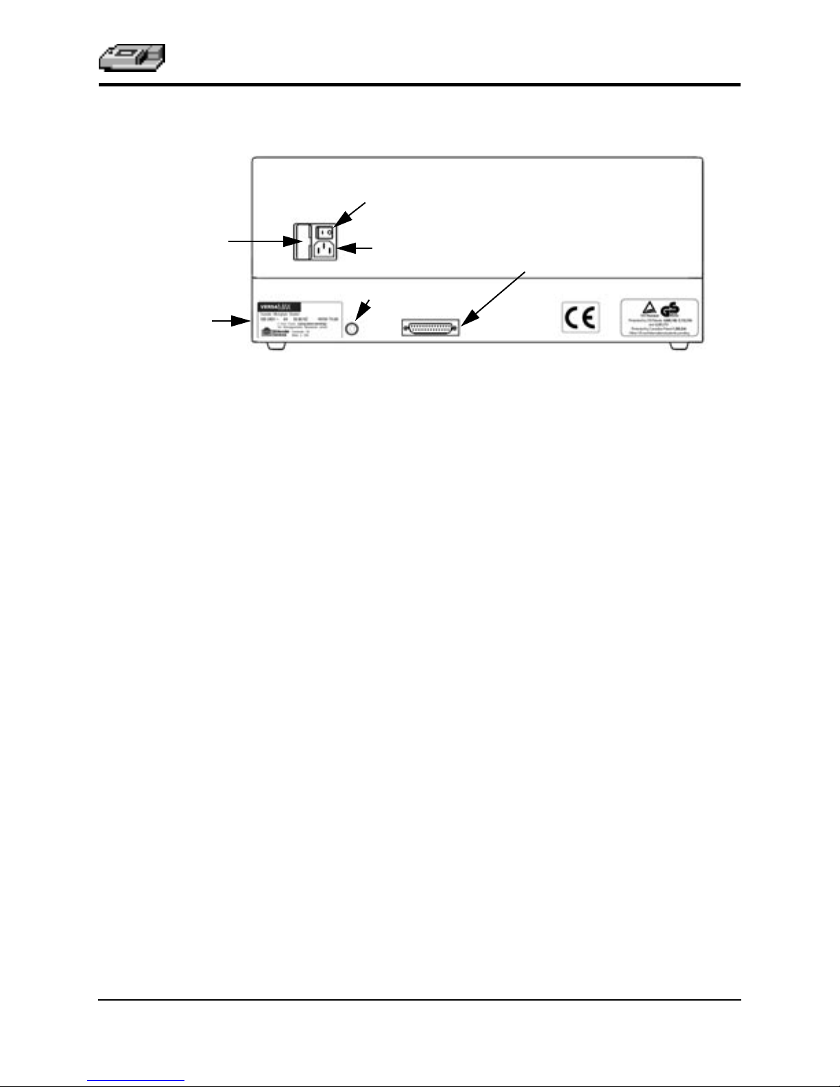
The Back Panel
Power Switch
Instrument Description
Fuse Box Cover
Label
Power Cord
Receptacle
Computer (RS-232)
Figure 1.5: Components on the Back Panel of the VERSAmax
The following components are located on the back panel of the VERSAmax
system:
Power switch —a rocker switch, labeled I/O (for on and off, respectively).
•
Power cord receptacle —plug the power cord in here.
•
Fuse box cover —cannot be opened while the power cord is plugged in.
•
When opened, it provides access to the fuse box containing two fuses that
are required for operation.
Computer port (double-shielded 8-pin RS-232 serial, for use with an exter-
•
nal computer)—plug the 8-pin DIN serial cable connector into this port; the
other end attaches to the serial (modem) port of the computer.
Labels —provide information about the VERSAmax, such as line voltage
•
rating, cautionary information, serial number, etc. Record the serial number
shown on this label for use when contacting Molecular Devices Technical
Services.
Printer Port (not used)
VERSAmax Tunable Microplate Reader Operator’s Manual 1-7
Page 16

Chapter 1
Functional
Description
Stand-Alone Operation
The VERSAmax has been designed to regulate the temperature of the microplate chamber from 4°C above ambient to 45°C. Upon power up, when
the incubator is off, the temperature in the VERSAmax microplate chamber
is ambient and isothermal. Pressing the incubator
cause the instrument to begin warming the microplate chamber. The temperature set point defaults to 37.0°C at start-up.
NOTE:
You can change the temperature set point by pressing the up (
(
▼
shown in the display. Typically, the microplate chamber will reach 37.0°C in
15 to 30 minutes.
The microplate chamber temperature is maintained at the set point until you
press the incubator
tion off. The microplate drawer will open and the temperature within the
chamber will begin returning to ambient.
Accuracy of the temperature set point is guaranteed only if the set
point is at least 4°C above ambient. If the temperature set point is
lower than the ambient temperature, the chamber temperature will
remain at ambient. Temperature regulation is controlled by heaters
only and, therefore, cannot cool the temperature to a setting lower
than ambient. Additionally, the highest setting (45°C) can be achieved
only if the ambient temperature is >20°C.
) arrow keys above and below the word TEMP until the desired set point is
[TEMP On/Off]
key again, turning temperature regula-
[TEMP On/Off]
▲
) or the down
key will
NOTE:
Temperature regulation within the microplate chamber is achieved through
electric heaters, a fan, efÞcient insulation, and temperature sensors. The heaters are located in the chamber which is insulated to maintain the temperature
set point. The sensors, also mounted inside the chamber, measure the air temperature. The temperature feedback closed-loop control algorithms compare
the measured air temperature inside the chamber against the temperature set
point, and use the difference to calculate the heating cycles. This technique
results in accurate, precise control of the chamber temperature with a temperature variation of the air inside the chamber of less than 1.0°C. (The temperature uniformity within the microplate will depend upon the design, materials,
and/or conÞguration of that component.)
Should you turn the incubator back on after a momentary shutdown,
allow about ten minutes after reaching temperature for the control
algorithm to fully stabilize the microplate chamber temperature.
1-8 VERSAmax Tunable Microplate Reader Operator’s Manual
Page 17

Instrument Description
Computer Control
The VERSAmax is equipped with an 8-pin DIN RS-232 serial port through
which a computer can communicate with and control the instrument.
SOFTmax PRO
Molecular Devices’ SOFTmax PRO software is a highly integrated program
that can be used to control and collect data from the VERSAmax.
SOFTmax PRO makes it possible to access the full capabilities of the
VERSAmax. SOFTmax PRO allows you to:
• Read microplates for endpoint and kinetic measurements
- Use up to two wavelengths for endpoint or kinetic measurements
- Perform Absorbance or %Transmittance readings in the 340- to 850-nm
range
- Program kinetic run times up to 99 hours
- Select your own read intervals for kinetic runs
- Specify the duration for Automix before and between readings
- Read the whole plate or a subset of microplate strips
• Design microplate templates to simplify data reduction
- Identify groups of wells with labels of your choice
- Identify individual wells with unique names
- Blank the entire plate, groups, and/or individual wells
• Save instrument settings, template formats, and data analysis parameters
for microplates as assay protocol Þles and recall them for later use
- Rapid instrument and analysis setup for repeated microplate assays
- Uniform analysis for equivalent microplates
•Turn the incubator on or off to control the temperature in the microplate
drawer
• Acquire data from the VERSAmax
- Save data files for in-depth analysis at a later time
- Save multiple microplates with individual template and data analysis pa-
rameters in one or more experiments in a single data file
- Pre-read microplates
- Analyze kinetic data as it is collected
• Use the Automix function to shake the microplate at preset intervals,
thereby mixing the contents of each well (highly recommended for ELISAs
and other solid-phase, enzyme-mediated reactions)
VERSAmax Tunable Microplate Reader Operator’s Manual 1-9
Page 18

Chapter 1
• Display data on screen
- Raw values, reduced number, or raw values with reduced number
- Raw microplate data in a microplate format
- Ranged data as integers between 0 and 9 in a microplate format
- Threshold data as being above, below, or between set limits in a microplate
format
- Gray scale data in seven shades of gray corresponding to high and low lim-
its in a microplate format
- Kinetic plots of all 96 microplate wells
- Enlarge the display of individual well plots and overlay multiple well
plots
• Perform data analysis using SOFTmax PRO features
- Calculate maximum kinetic rates on non-linear data
- Assign plate, group, or sample blanks
- Customize data analysis for each group in the template
- Create graphs with multiple plots
- Pick from nine curve-fitting routines
- Analyze unknown samples against a standard curve
- Analyze and compare data within a plate, between plates, and between ex-
periments
• Multiple print formats
- Print all or individual sections of the data file
- Define and print a report containing only selected sections
- Customize the order of data file sections
• Export data in tab-delimited ASCII format for use with Excel or other database programs
For a complete description of the features of SOFTmax PRO, refer to the
SOFTmax PRO User’s Manual .
1-10 VERSAmax Tunable Microplate Reader Operator’s Manual
Page 19

, 0 –
, 0 –
Instrument Description
SpeciÞcations
Wavelength bandwidth ≤ 2.0 nm FWHM (full width half maximum)
Wavelength repeatability ± 0.2 nm across all optical channels
Photometric resolution 0.001 OD
Photometric accuracy/linearity
(microplate)
(repeatability)
Thermal speciÞcations for microplates used in the VERSAmax apply to ßatbottom microplates with isolated wells. All other microplate speciÞcations
apply to standard 96-well polystyrene ßat-bottom microplates.
NOTE:
Technical speciÞcations are subject to change without notice.
Photometric Performance
Wavelength range 340–850 nm
Wavelength selection Monochromator tunable in 1-nm increments
Wavelength accuracy ± 1.0 nm across wavelength range
Photometric range -0.3 to 4.000 OD
2.0 OD: 340–850 nm <± 1.0% and ± 0.006 OD
Photometric precision
2.0 OD: 340–850 nm <± 1.0% and ± 0.003 OD
Stray light ≤ 0.05% at 340 nm
Photometric stabilization Instantaneous
Photometric drift None—continuous referencing of monochromatic output
Calibration Automatic before first kinetic read and before every end-
point reading
Optical alignment None required
Light source Xenon flash lamp (5 watts)
Average lamp lifetime
Illumination
Photodetectors
1 billion flashes
Top down
Silicon photodiode
Photometric Analysis Modes
Using SOFTmax PRO
• Express data as Absorbance or %Transmittance
• Single wavelength reading of microplate
•
Dual wavelength reading of microplate
• Kinetic and kinetic graphics of microplate
VERSAmax Tunable Microplate Reader Operator’s Manual 1-11
Page 20

Chapter 1
Read time (endpoint)
--
Standard read*
Reading chamber
Measurement Time (calibration off)
• 96 wells in 9 seconds (single wavelength)
• 96 wells in 19 seconds (dual wavelength—425 & 650 nm)
Kinetic read intervals
val between readings (single wavelength)
•1 column, 2-second minimum interval between readings
(single wavelength)
•96 wells, 9-second minimum inter-
Temperature Regulation
Isothermal when temperature regulation is not enabled
Range
Resolution
Accuracy
Temperature uniformity at equilibrium ± 0.5°C at 37°C
Chamber warm-up time 15-30 minutes (measured on air) after initiation of temper-
Temperature regulation 4 sensors
Drift ± 0.2°C (regulated)
Temperature regulation diagnostics
Recommended microplate Flat-bottom microplates with isolated wells
4°C above ambient to 45°C when temperature regulation
enabled. The ambient temperature must be >20°C to
achieve temperature regulation at 45°C.
± 0.1°C
± 1.0°C
ature regulation
Temperature regulation system is continuously monitored
and updated
(use of plate films not recommended)
Automix with SOFTmax PRO
Plate mixing modes Selectable: off, once prior to any reading, and once prior to
and between kinetic readings
Plate mixing duration Selectable: 1 to 999 seconds (three-second default)
1-12 VERSAmax Tunable Microplate Reader Operator’s Manual
Page 21

Instrument Description
Compatibility
Microplate Standard and half-area 96-well flat-bottomed microplates
(0.3 mL).
VERSAmax Tunable Microplate Reader Operator’s Manual 1-13
Page 22

Chapter 1
General Instrument
Display 2-×-20-character backlit LCD
Operating panel 4 key membrane keypad
Self-diagnosis Continuous on-board diagnostics
Spill control Drawer mechanism/reading chamber assembly is protect-
ed from accidental spillage by drainage ports
Computer interface 8-pin DIN RS-232 serial (double shielding required)
Microplates supported All 96-well and strip-well microplates
Environmental
For indoor use only
Operating temperature 5 to 40°C
Operating altitude < 2000 m
Installation category II
Pollution degree 2
Operating humidity < 80%
Storage temperature -20 to 65°C
Physical
Size (h × w × d) 8.6 in. (22 cm) × 22.8 in. (58 cm) × 15 in. (38 cm)
Weight 30 lb (13.6 kg)
Power consumption < 250 watts
Line voltage 100-240 VAC, 4 A
Line frequency 50/60 Hz
1-14 VERSAmax Tunable Microplate Reader Operator’s Manual
Page 23

Chapter 2 Installation
Installation Warnings. . . . . . . . . . . . . . . . . . . . . . . . . . . . . . .2-3
Installation Cautions . . . . . . . . . . . . . . . . . . . . . . . . . . . . . . .2-3
Unpacking . . . . . . . . . . . . . . . . . . . . . . . . . . . . . . . . . . . . . . . .2-3
Setting Up for Stand-Alone Use. . . . . . . . . . . . . . . . . . . . . .2-4
Page 24

Chapter 2
2-2 VERSAmax Tunable Microplate Reader Operator’s Manual
Page 25

Installation
Warnings
Installation
1) Always make sure the power switch on the instrument is in the OFF position
and remove the power cord from the back of the instrument prior to any installation or relocation of the instrument.
2) Do not operate the instrument in an environment where potentially damaging liquids or gases are present.
Installation
Cautions
Do not touch or loosen any screws or parts other than those speciÞcally designated in the instructions. Doing so might cause misalignment and will void
the instrument warranty.
Unpacking The VERSAmax is packed in a specially designed carton. Please retain the car-
ton and the packing materials. If the unit should need to be returned for
repair, you must use the original packing materials and carton for shipping. If
the carton has been damaged in transit, it is particularly important that you
retain it for inspection by the carrier in case there has also been damage to the instrument.
WARNING:
should be lifted with care. It is recommended that two persons lift the
instrument together, taking the proper precautions to avoid injury.
After examining the carton, place it on a ßat surface in the upright position.
Open the top of the box and lift the VERSAmax, along with the packing materials around the ends, up and out of the shipping box. Remove the packing
material from both ends of the instrument and set the instrument down carefully.
The VERSAmax weighs approximately 30 lb (13.6 kg) and
VERSAmax Tunable Microplate Reader Operator’s Manual 2-3
Page 26
Chapter 2
Setting Up for
Stand-Alone
Use
1) Place the VERSAmax on a level surface, away from direct sunlight, dust, drafts,
vibration, and moisture.
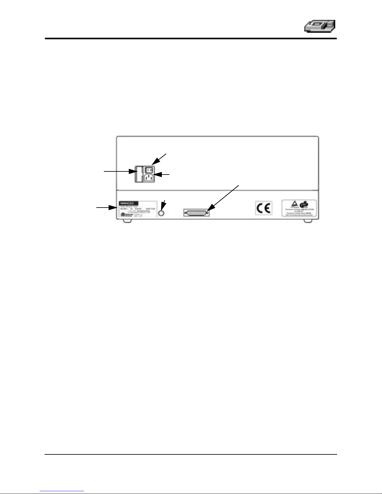
2) Turn the instrument around so that the back of the instrument is facing you as
shown in Figure 2.1.
Power Switch
Fuse Box Cover
Label
Power Cord
Receptacle
Computer (RS-232)
Figure 2.1: View of Rear Panel
3) Insert the appropriate (Macintosh or PC) serial interface cable into the RS-232
serial port on the VERSAmax. Connect the other end to the serial port of the
computer.
4) Insert the female end of the power cord into the power receptacle at the rear
of the VERSAmax. Connect the male end to a grounded power outlet of the
appropriate voltage. Molecular Devices recommends that you use a surge
protector between the power cord and the grounded power outlet.
5) Turn the VERSAmax around so that the control panel now faces you. Be sure
no cables run beneath the instrument. Leave at least three inches between the
back of the instrument and the nearest objects or surfaces to ensure proper
ventilation and cooling.
6) Turn on the power to the VERSAmax, wait for the microplate drawer to open,
and remove the tape and protective covering from the drawer subplate.
Printer Port (not used)
2-4 VERSAmax Tunable Microplate Reader Operator’s Manual
Page 27

Chapter 3 Stand-Alone Operation
Prepare for a Reading . . . . . . . . . . . . . . . . . . . . . . . . . . . . . .3-3
Turn the Instrument On. . . . . . . . . . . . . . . . . . . . . .3-3
Set the Temperature . . . . . . . . . . . . . . . . . . . . . . . . .3-3
Page 28

Chapter 3
3-2 VERSAmax Tunable Microplate Reader Operator’s Manual
Page 29

Stand-Alone Operation
This chapter contains operating information for the VERSAmax Tunable Microplate
Reader.
Prepare for a
Reading
NOTE:
Only temperature selection is available in stand-alone mode through
front panel control. To achieve full use of this instrument, connect it to
a computer and use SOFTmax PRO software.
Turn the Instrument On
The power switch for the VERSAmax is located on the back panel. Press the
rocker switch to the ON position. The instrument will automatically perform
diagnostic checks to ensure that it is functioning correctly. Turn the printer on
at the same time.
Set the Temperature
If elevated temperature within the microplate chamber is required, you
should turn on the incubator Þrst, allowing enough time for the temperature
to reach the set point before performing a reading. When you Þrst turn the
instrument on, up to 30 minutes may be required for the temperature within
the chamber to reach the set point.
To enable the incubator, press the incubator
display will update to show the temperature set point and the current chamber temperature.
To change the temperature set point, press the up or down arrows above and
below TEMP until the desired temperature set point is shown in the display.
[TEMP On/Off] key. The LCD
The microplate chamber temperature will be maintained at the set point until
you disable temperature control by touching the incubator
key again. When the incubator is off, the drawer will open and the temperature within the chamber will begin returning to ambient.
NOTE:
Should you turn the incubator back on after a momentary shutdown,
allow about ten minutes for the control algorithm to fully stabilize the
chamber temperature.
[TEMP On/Off]
VERSAmax Tunable Microplate Reader Operator’s Manual 3-3
Page 30

Chapter 3
3-4 VERSAmax Tunable Microplate Reader Operator’s Manual
Page 31

Chapter 4 Maintenance and Troubleshooting
Technical Support. . . . . . . . . . . . . . . . . . . . . . . . . . . . . . . . . .4-3
Warnings and Cautions. . . . . . . . . . . . . . . . . . . . . . . . . . . . .4-3
General. . . . . . . . . . . . . . . . . . . . . . . . . . . . . . . . . . . . . . . . . . .4-4
Cleaning. . . . . . . . . . . . . . . . . . . . . . . . . . . . . . . . . . . . . . . . . .4-4
Changing the Fan Filter. . . . . . . . . . . . . . . . . . . . . . . . . . . . .4-4
Changing the Fuses . . . . . . . . . . . . . . . . . . . . . . . . . . . . . . . .4-5
Error Codes and Probable Causes . . . . . . . . . . . . . . . . . . . .4-7
Error Messages . . . . . . . . . . . . . . . . . . . . . . . . . . . . .4-7
Opening the Drawer Manually . . . . . . . . . . . . . . . . . . . . .4-11
Page 32

Chapter 4
4-2 VERSAmax Tunable Microplate Reader Operator’s Manual
Page 33

Maintenance and Troubleshooting
This chapter lists maintenance procedures and troubleshooting information, including error codes that may be seen, followed by their most likely causes and remedies.
Technical
Support
Warnings and
Cautions
Molecular Devices Corporation is a leading worldwide manufacturer and distributor of analytical instrumentation. We are committed to the quality of our
products and to fully supporting our customers with the highest level of technical service. In order to fully beneÞt from our technical services, please complete the registration card and return it to the address printed on the card.
If you have any problems using the VERSAmax Tunable Microplate Reader
that are not covered in this chapter, in the U.S., contact our Technical Services
group at 1-800-635-5577; elsewhere contact your local representative.
BIOHAZARD:
as well as any accessories, before requesting service by Molecular
Devices representatives and before returning the instrument or any
components to Molecular Devices Corporation.
WARNING:
safely performed by qualiÞed personnel. Maintenance not covered in
this manual should be performed by a Molecular Devices representative.
WARNING:
Voltage warning symbol shown below can result in a safety hazard.
It is your responsibility to decontaminate the instrument,
All maintenance procedures described in this manual can be
Removal of protective covers that are marked with the High
WARNING:
and any computer/printer cables from the back prior to any maintenance or installation operation
WARNING:
ronment where liquids or potentially damaging gases are present.
WARNING:
nel.
CAUTION:
!
harm to the optics in the VERSAmax. Extreme caution is advised
when using organic solvents. Always use a plate lid and avoid placing
a plate containing these materials in the reading chamber for prolonged periods of time. Damage caused by the use of incompatible or
aggressive solvents is NOT covered by the instrument warranty.
CAUTION:
!
housing, or manifold. The optics are extremely delicate, and critical to
the instrument.
Do not touch or loosen any screws or parts other than those
CAUTION:
!
speciÞcally designated in the instructions. Doing so could cause misalignment and possibly void warranty.
Always turn the instrument off and remove the power cord
Never perform any operation on the instrument in an envi-
Risk of electrical shock. Refer servicing to qualiÞed person-
Use of organic solvents (such as dichloromethane) may cause
Never touch any of the optic mirrors, Þlters, or cables or their
VERSAmax Tunable Microplate Reader Operator’s Manual 4-3
Page 34

Chapter 4
General Keep the drawer closed when the instrument is not in use. The drawer can be
opened by pressing the DRAWER button. Always close the drawer immediately prior to switching the instrument off.
Cleaning Wear gloves during any cleaning procedure that could
Cleaning the
Fan Filter
1) Turn power to the instrument OFF and then remove the power cord and
BIOHAZARD:
involve contact with either hazardous or biohazardous materials or
ßuids.
Periodically, you should clean the outside surfaces of the VERSAmax using a
cloth or sponge that has been dampened with water. Do not use abrasive
cleaners. If required, clean the surfaces using a mild soap solution diluted
with water or a glass cleaner and then wipe with a damp cloth or sponge to
remove any residue. Do not spray cleaner onto the instrument.
If needed, clean the microplate drawer using a cloth or sponge that has been
dampened with water.
Should ßuids spill in the drawer area when the drawer is out, they will be
directed to a tray at the bottom of the instrument from which they will exit to
the bench or counter beneath the instrument. Wipe up any spills immediately.
Clean only the exterior of the unit (and the microplate drawer, if necessary).
Never clean the inside of the instrument. Do not allow excess water or other
ßuids to drip inside the instrument.
The fan Þlter on the bottom of the instrument requires periodic cleaning. The
frequency of the cleaning depends on how dusty your particular lab is and
could range from once a month to once every six months.
cables from the back of the instrument.
2) Make sure no plate is in the instrument. Turn the instrument over so that it
rests ßat on the bench.
3) Pop the black fan cover off and remove the Þlter.
4) Clean the Þlter by blowing clean, canned air through it or by rinsing it—Þrst
with water and then with alcohol—and allowing it to dry completely.
5) Place the clean, dry Þlter over the fan and replace the black cover.
6) Turn the instrument back over. Reconnect the power cord and cables to the
instrument.
4-4 VERSAmax Tunable Microplate Reader Operator’s Manual
Page 35

Maintenance and Troubleshooting
Changing the
Fuses
Fuses burn out occasionally and must be replaced. If the instrument does not
seem to be getting power after switching it on (the LCD shows no display),
Þrst check to see whether the power cord is securely plugged into a functioning power outlet and into the receptacle at the rear of the VERSAmax. If
power failed while the VERSAmax was already on, check that the power cord
is not loose or disconnected and that power to the power outlet is functioning
properly. If these checks fail to remedy the loss of power, follow the steps
listed below to replace the fuses. Spare fuses (two U.S. and two metric) are
shipped with the instrument. The U.S. and metric fuses are identical except
for physical size. They may be taped to the back of the VERSAmax.
If you no longer have spare fuses, you may obtain new ones from Molecular
Devices (part numbers: 4601-0013 for U.S., 4601-0014 for metric) or from a
local hardware store. Make sure fuses are rated SLOWBLOW (U.S.: 4-amp
time-delay; metric: 4-amp, 5 × 20 mm, time-delay).
To change fuses, follow the steps below.
1) Switch power to the instrument off and then remove the power cord from the
outlet and from the VERSAmax power cord receptacle.
2) Remove the printer cable and computer cable (if connected) from the back of
the VERSAmax.
3) Turn the instrument around for easy access to the rear panel.
4) On the left-hand side of the rear panel (viewed from the back) are the power
switch, fuse box, and power cord receptacle. As shown in the Þgures below,
press to the right of the black plastic cover of the fuse box to release it. Pull the
fuse box cover away from the instrument. The fuse box will begin to slide forward.
Figure 4.1: Power Switch, Fuse Box, and Power Receptacle
VERSAmax Tunable Microplate Reader Operator’s Manual 4-5
Fuse Box Cover
Page 36

Chapter 4
5) Continue gently pulling the fuse box forward until it is free of the instrument.
Figure 4.2: Removing the Fuse Box
6) When removed, the fuse assembly will appear as shown in Figure 4.3. The
holder inside contains two fuses.
7) It is possible that only one of the fuses may have blown. Molecular Devices
recommends that you replace both fuses, however, to ensure continued
proper operation. Pull both fuses out of the holder and discard them.
Figure 4.3: The Fuse Box and Holder (with Fuses) Removed
8) Insert new SLOWBLOW-rated fuses into the fuse holder. Either end of the
fuse may be forward.
9) Insert the fuse box into the opening in the instrument, making sure that the
fuses are on the right side (toward the power receptacle). Press the fuse box
into place, making sure the cover snaps closed.
10) Reconnect the power cord to the instrument and to the wall outlet and reconnect other cables previously disconnected.
4-6 VERSAmax Tunable Microplate Reader Operator’s Manual
Page 37

Maintenance and Troubleshooting
Error Codes
and Probable
Causes
If a problem occurs during operation that causes an unrecoverable error, the
instrument will stop and an error code number will be shown in the display
on the front panel. To correct the problem, call your local Molecular Devices
representative for assistance.
Error Messages
The LCD will display Fatal Error codes when a situation arises that requires
attention. Any reading in progress will stop. Warning messages do not stop a
reading but are logged in the error buffer. Warning messages indicate a situation that requires attention but is not sufÞcient to stop or prevent a reading.
Examples of situations that might cause warning messages are low memory,
entries being out of range, or operations that could result in loss of data. These
messages are generally self-explanatory. For assistance regarding warning
messages, contact your local Molecular Devices representative.
Error Code ClassiÞcations
Not all error messages are listed in this manual. The errors are grouped in
relationship to possible causes as follows:
Error Code Numbers Possible Causes
100 -199 Errors possibly caused by unrecognized commands being sent from the computer
to the instrument.
200-299 Errors probably due to a main board failure or an error in the firmware code.
Most of these errors require the assistance of Technical Support.
300-399 Instrument errors due to either a main board failure or other system failure. Most
of these errors require the assistance of Technical Support.
400-499 Errors caused by a motor motion failure. Most of these errors require the assis-
tance of Technical Support.
500-599 Errors due to failure or improper initialization of the instrument’s non-volatile
memory (NVRAM). All of these errors require the assistance of Technical Support.
Some errors (shown in boldface in this manual) are considered fatal if they
are detected during power up (the instrument will abort the power up
sequence and display “FATAL ERROR ###” on the LCD panel). Check the
following table to see if you can do something to prevent the fatal error. After
correcting the problem, leave the instrument on for about Þve minutes, turn it
off and then back on. If you continue to get the fatal error message on powerup, record the error message number and contact Molecular Devices Technical Support or your local representative for assistance.
NOTE:
If the instrument is functioning normally when using SOFTmax
PRO, no errors should be in the buffer (except error number 100).
VERSAmax Tunable Microplate Reader Operator’s Manual 4-7
Page 38

Chapter 4
Table 4.1. Error Codes, Messages, and Notes about the Errors
ERROR
CODE
ERROR MESSAGE NOTES
100-199: Unrecognized Command Errors Sent from the Computer
100 command not found Command string not recognized.
101 invalid argument Command Argument not recognized.
102 too many arguments Too many arguments after command.
103 not enough arguments Missing arguments.
104 input line too long Too many characters in the input line.
105 command invalid, sys-
tem busy
Instrument could not perform the give command because it was
busy doing another task. Example: Request a wavelength while
the monochromator is in motion.
106 command invalid, mea-
surement in progress
Instrument could not perform command because a measurement
was in progress
107 no data to transfer Inputting transfer when there’s no data in the buffer
108 data buffer full To many data sets in the buffer. Can be caused by setting up a
long kinetic and disconnecting computer, or if SOFTmax PRO is
preempted by another application.
109 error buffer overflow More than 65 errors in the buffer, clear the buffer.
110 stray light
111 invalid read settings
200-299: Firmware Errors
200 assert failed Firmware error.
201 bad error number Firmware error.
202 receive queue overflow Caused by external device sending too much data over serial port
and ignoring flow control.
203 serial port parity error Parity bit error detected with incoming serial data.
204 serial port overrun error Caused by host computer sending too much data and ignoring
the flow control signal.
205 serial port framing error
206 cmd generated too
Firmware error.
much output
4-8 VERSAmax Tunable Microplate Reader Operator’s Manual
Page 39

Table 4.1. Error Codes, Messages, and Notes about the Errors
Maintenance and Troubleshooting
ERROR
CODE
ERROR MESSAGE NOTES
207 fatal trap Instrument error. Instrument locks up.
208 RTOS error Firmware error.
209 stack overflow Firmware error.
210 unknown interrupt Firmware error.
300-399: Hardware Errors
300 thermistor faulty Unable to read a reasonable thermistor value. Thermistor faulty
or disconnected, Main board problem, or ambient temperature
out of range.
301 safe temperature limit
exceeded
A temperature of over 50°C detected on one or more of the 4
thermistors. Temperature will be shut off and remain off until a
successful completion of power-up reset.
302 low light Not enough light detected to make an accurate measurement.
303 unable to cal dark cur-
rent
Too much stray light detected on power-up, faulty or disconnected pre-amp boards.
304 signal level saturation
305 reference level saturation
306 plate air cal fail, low
Minimum signal/reference ratio not met during air calibration.
light
307 cuv air ref fail
308 stray light Light leak in reading chamber. Could also be a faulty pre-amp
board.
309 front panel not respond-
LCD front panel bad or disconnected.
ing
310
311
312 gain calibration failed Power-up calibration and check of signal path gain is out of tol-
erance. Could be due to bad or disconnected pre-amp or excessive stray light.
313 reference gain check fail Power-up check of the Reference amplifier's gain out of toler-
ance. Could be due to bad or disconnected pre-amp board or
excessive stray light.
314 low lamp level warning
VERSAmax Tunable Microplate Reader Operator’s Manual 4-9
Page 40

Chapter 4
Table 4.1. Error Codes, Messages, and Notes about the Errors
ERROR
CODE
ERROR MESSAGE NOTES
315 can't find zero order On power-up grating motor could not find zero-order home
position.
316 grating motor driver
faulty
Grating motor didn’t move to where it was commanded to in a
reasonable time.
317 monitor ADC faulty
400-499: Motion Errors
400 carriage motion error Carriage did not move to either of its photo interrupts in a rea-
sonable time, or can’t find its photo interrupt.
401 filter wheel error Filter wheel did not move to its photo interrupt in a reasonable
time, or can’t find its photo interrupt.
402 grating error Grating did not move to its photo interrupt in a reasonable
time, or can’t find its photo interrupt.
403 stage error Stage did not move to its photo interrupt in a reasonable time,
or can’t find its photo interrupt.
500-599: NVRAM Errors
500 NVRAM CRC corrupt The CRC for the NVRAM data is corrupt.
501 NVRAM Grating cal
Grating calibration data is unreasonable.
data bad
503 NVRAM Plate air cal
Plate air calibration data is unreasonable.
data error
504 NVRAM Carriage offset
Carriage offset data is unreasonable.
error
505 NVRAM Stage offset
Stage offset data is unreasonable.
error
506 NVRAM Battery Time to replace the NVRAM battery (U3).
4-10 VERSAmax Tunable Microplate Reader Operator’s Manual
Page 41

Maintenance and Troubleshooting
Opening the
Drawer
Manually
If an error occurs while the drawer is closed and you need to open the drawer,
press the
ment off and then on again.
If the drawer still remains closed, turn the power off and using your thumb
nail, locate the groove in the upper left side wall of the door. Open the door,
and with your index Þnger, pull the microplate drawer out of the instrument
(do not force the drawer) and remove the microplate. This action will not harm
the instrument, but should be taken only if the Þrst two options have failed to
open the drawer.
If you are still unable to open the drawer, contact Molecular Devices Technical
Support or your local representative for assistance.
[Drawer] key. If the drawer does not open, turn power to the instru-
VERSAmax Tunable Microplate Reader Operator’s Manual 4-11
Page 42

Chapter 4
4-12 VERSAmax Tunable Microplate Reader Operator’s Manual
Page 43

Appendix A Printers and Cables
Compatible
Printers
This section intentionally left blank because the VERSAmax
does not support printing directly from the instrument.
Cables Molecular Devices recommends that you use high-quality,
double-shielded cables to connect the VERSAmax to the computer. Choose cables that meet the following requirements:
Serial Interface Cable
(contact Molecular Devices for speciÞc pin-out requirements)
Macintosh: Male DB8 to Male DB8
IBM Compatible: Male DB8 to Female DB8 (custom cable
made by Molecular Devices)
Page 44

Appendix A
A-2 VERSAmax Tunable Microplate Reader Operator’s Manual
Page 45

Appendix B Accessories
Items
Available for
Use with the
VERSAmax
Cable, RS-232, Macintosh to VERSAmax
8-pin DIN to 8-pin DIN 9000-0091
Cable, RS-232, PC to VERSAmax
9-pin to 8-pin DIN 9000-0149
Fuse, 4-amp (5 × 20 mm) Time Delay 4601-0014
Power Cord (US, Canada, Japan, Mexico, India) 4400-0002
Power Cord, EC1
(Germany, France, Scandinavia, Italy, Korea) 4400-0036
Part Number
Power Cord, EC2
(UK, Indonesia, Singapore, Malaysia) 4400-0037
Power Cord, AP1 (Australia, Hong Kong, China) 4400-0038
SPECTRAtest VERSAmax Validation Package 0200-2405
Page 46

Appendix B
B-2 VERSAmax Tunable Microplate Reader Operator’s Manual
Page 47

Index
B
Back panel 1-7
Bandwidth 1-11
C
Cable, serial 1-7
Calibration 1-11
Cleaning 4-4
Computer control 1-9
Connections 1-4, 1-7
Control panel 1-4
Control panel display 1-5
D
Drawer
key 1-5, 1-6
open manually 4-11
E
Error Messages 4-7
F
Fan filter 4-4
Fuses 4-5
accessing 1-7
I
Incubator 1-6, 1-8, 3-3
Installation 2-3
K
Keys (control panel) 1-4
L
Labels 1-7
LCD (Liquid Crystal Display) 1-4, 4-7
M
Microplate
96-well 1-6
filter-bottom 1-6
strip wells 1-6
temperature uniformity 1-6
Microplate drawer 1-4, 1-5, 1-6
closing 1-6
incubator status 1-6
P
Ports 2-4
serial 1-7
Power cord 1-7, 2-4, 6-1
Power switch 1-4, 1-7, 3-3
Printer 3-3
R
Read mode 1-9
Read the microplate 1-9
Remote control 1-9
S
Serial port 1-7
Set point 1-5
Set point, temperature 1-5
SOFTmax PRO 1-9
Specifications 1-11
Spills 4-4
Stand-alone operation 1-8, 2-4
T
Technical service 4-3
Temperature 1-8
equilibration 1-8, 3-3
regulation 1-8
set point 1-5, 1-8, 3-3
VERSAmax Tunable Microplate Reader Operator’s Manual Index-1
W
Warranty i-ii
Wavelength
range 1-11
 Loading...