

Molecular Devices SpectraMax M3, SpectraMax M4, SpectraMax M5e, SpectraMax M5 User Manual
SpectraMax® M3, M4, M5, and M5e
Multi-Mode Microplate Readers
User Guide
0112-0115 F
July 2010

This document is provided to customers who have purchased Molecular Devices, Inc.
(“Molecular Devices”) equipment, software, reagents, and consumables to use in the
operation of such Molecular Devices equipment, software, reagents, and
consumables. This document is copyright protected and any reproduction of this
document, in whole or any part, is strictly prohibited, except as Molecular Devices
may authorize in writing.
Software that may be described in this document is furnished under a license
agreement. It is against the law to copy, modify, or distribute the software on any
medium, except as specifically allowed in the license agreement. Furthermore, the
license agreement may prohibit the software from being disassembled, reverse
engineered, or decompiled for any purpose.
Portions of this document may make reference to other manufacturers and/or their
products, which may contain parts whose names are registered as trademarks and/or
function as trademarks of their respective owners. Any such usage is intended only
to designate those manufacturers' products as supplied by Molecular Devices for
incorporation into its equipment and does not imply any right and/or license to use
or permit others to use such manufacturers' and/or their product names as
trademarks.
Molecular Devices makes no warranties or representations as to the fitness of this
equipment for any particular purpose and assumes no responsibility or contingent
liability, including indirect or consequential damages, for any use to which the
purchaser may put the equipment described herein, or for any adverse circumstances
arising therefrom.
For research use only. Not for use in diagnostic procedures.
The trademarks mentioned herein are the property of Molecular Devices, Inc. or their
respective owners. These trademarks may not be used in any type of promotion or
advertising without the prior written permission of Molecular Devices, Inc.
Product manufactured by Molecular Devices, Inc.
1311 Orleans Drive, Sunnyvale, California, United States of America 94089.
Molecular Devices, Inc. is ISO 9001 registered.
© 2010 Molecular Devices, Inc.
All rights reserved.
Printed in the USA.
Contents
Chapter 1 Description . . . . . . . . . . . . . . . . . . . . . . . . . . . 7
Introduction . . . . . . . . . . . . . . . . . . . . . . . . . . . . . . . . . 7
Applications. . . . . . . . . . . . . . . . . . . . . . . . . . . . . . . . . 8
Certified SpectraMax® M5e-HTRF Readers . . . . . . . . . . . . 8
Optics. . . . . . . . . . . . . . . . . . . . . . . . . . . . . . . . . . . . . 8
Dynamic Range . . . . . . . . . . . . . . . . . . . . . . . . . . . . . . 8
PathCheck® Pathlength Measurement Technology . . . . . . 9
Automix . . . . . . . . . . . . . . . . . . . . . . . . . . . . . . . . . . . 9
Temperature Control . . . . . . . . . . . . . . . . . . . . . . . . . . 9
Supported Plates . . . . . . . . . . . . . . . . . . . . . . . . . . . . . 9
Computer Control . . . . . . . . . . . . . . . . . . . . . . . . . . . . 10
Instrument Control. . . . . . . . . . . . . . . . . . . . . . . . . . . 10
Data Collection and Display . . . . . . . . . . . . . . . . . . . . . 10
Data Reduction and Plotting . . . . . . . . . . . . . . . . . . . . 10
Immediate Results Reporting and Analysis . . . . . . . . . . 10
Reader Components . . . . . . . . . . . . . . . . . . . . . . . . . . . 11
The Control Panel. . . . . . . . . . . . . . . . . . . . . . . . . . . . 12
Temp On/Off . . . . . . . . . . . . . . . . . . . . . . . . . . . . . . 13
Temp . . . . . . . . . . . . . . . . . . . . . . . . . . . . . . . . . . . 13
Wavelengths (
Ref . . . . . . . . . . . . . . . . . . . . . . . . . . . . . . . . . . . . . 14
Read Cuvette. . . . . . . . . . . . . . . . . . . . . . . . . . . . . . 14
Mode . . . . . . . . . . . . . . . . . . . . . . . . . . . . . . . . . . . 14
Drawer . . . . . . . . . . . . . . . . . . . . . . . . . . . . . . . . . . 14
The Microplate Drawer . . . . . . . . . . . . . . . . . . . . . . . . 15
Microplates . . . . . . . . . . . . . . . . . . . . . . . . . . . . . . . 16
The Cuvette Chamber. . . . . . . . . . . . . . . . . . . . . . . . . 17
Cuvettes . . . . . . . . . . . . . . . . . . . . . . . . . . . . . . . . . 17
The Back Panel . . . . . . . . . . . . . . . . . . . . . . . . . . . . . 18
0112-0115 F 3
Contents
Chapter 2 Principles of Operation . . . . . . . . . . . . . . . . . 19
Absorbance . . . . . . . . . . . . . . . . . . . . . . . . . . . . . . . . . 19
Optical Density. . . . . . . . . . . . . . . . . . . . . . . . . . . . . . . 19
Transmittance . . . . . . . . . . . . . . . . . . . . . . . . . . . . . . . 19
PathCheck® Pathlength Measurement Technology . . . . . . 19
Water Constant or Cuvette Reference? . . . . . . . . . . . . . 22
Background Considerations . . . . . . . . . . . . . . . . . . . . . 22
PathCheck Pathlength Measurement Technology
and Interfering Substances . . . . . . . . . . . . . . . . . . . . . 23
Normalizing Absorbance Measurements. . . . . . . . . . . . . 24
Fluorescence . . . . . . . . . . . . . . . . . . . . . . . . . . . . . . . . 24
Time-resolved Fluorescence (M4, M5, and M5e only) . . . . 27
Fluorescence Polarization (M5 and M5e only) . . . . . . . . . . 28
Luminescence . . . . . . . . . . . . . . . . . . . . . . . . . . . . . . . 28
Functional Description. . . . . . . . . . . . . . . . . . . . . . . . . . 29
Temperature Regulation . . . . . . . . . . . . . . . . . . . . . . . 29
Read Types . . . . . . . . . . . . . . . . . . . . . . . . . . . . . . . . . 30
Endpoint Read . . . . . . . . . . . . . . . . . . . . . . . . . . . . . 30
Kinetic Read. . . . . . . . . . . . . . . . . . . . . . . . . . . . . . . 30
Spectrum Read. . . . . . . . . . . . . . . . . . . . . . . . . . . . . 30
Well Scan Read . . . . . . . . . . . . . . . . . . . . . . . . . . . . 31
Automix . . . . . . . . . . . . . . . . . . . . . . . . . . . . . . . . . . 31
Computer Control . . . . . . . . . . . . . . . . . . . . . . . . . . . . 31
Chapter 3 Installation . . . . . . . . . . . . . . . . . . . . . . . . . . 33
Unpacking . . . . . . . . . . . . . . . . . . . . . . . . . . . . . . . . . . 34
Setting up the Instrument . . . . . . . . . . . . . . . . . . . . . . . 35
Installing the Drawer Adapter . . . . . . . . . . . . . . . . . . . . 36
Removing the Drawer Adapter . . . . . . . . . . . . . . . . . . . . 37
4 0112-0115 F
SpectraMax M3, M4, M5, and M5e Multi-Mode Microplate Readers
Chapter 4 Operation . . . . . . . . . . . . . . . . . . . . . . . . . . . 39
Cuvette Read—Quick Overview . . . . . . . . . . . . . . . . . . . 39
Microplate Read—Quick Overview . . . . . . . . . . . . . . . . . 40
Preparing for a Cuvette or Microplate Reading . . . . . . . . . 40
Turn the Instrument and Computer On . . . . . . . . . . . . . 40
Set the Temperature (Optional) . . . . . . . . . . . . . . . . . . 41
Select the Wavelength . . . . . . . . . . . . . . . . . . . . . . . . 42
Read the Cuvette . . . . . . . . . . . . . . . . . . . . . . . . . . . . . 43
Read the Microplate . . . . . . . . . . . . . . . . . . . . . . . . . . . 43
Optimizing Fluorescence Assays. . . . . . . . . . . . . . . . . . . 44
Optimizing Absorbance Assays . . . . . . . . . . . . . . . . . . . 44
Excitation and Emission Wavelengths . . . . . . . . . . . . . 44
Emission Cutoff Filter . . . . . . . . . . . . . . . . . . . . . . . . 45
Readings Per Well . . . . . . . . . . . . . . . . . . . . . . . . . . 45
PMT Voltage . . . . . . . . . . . . . . . . . . . . . . . . . . . . . . 45
Temperature Control . . . . . . . . . . . . . . . . . . . . . . . . 45
Using Spectral Scanning to Optimize Excitation
and Emission Wavelengths for Fluorescence Assays . . . . 46
Optimizing Time-resolved Fluorescence Assays . . . . . . . . 50
Optimizing Fluorescence Polarization Assays . . . . . . . . . . 51
Optimizing Luminescence Assays . . . . . . . . . . . . . . . . . . 52
Chapter 5 Maintenance . . . . . . . . . . . . . . . . . . . . . . . . . 53
Technical Support . . . . . . . . . . . . . . . . . . . . . . . . . . . . 53
Moving a SpectraMax Multi-Mode Microplate Reader. . . . . 55
General . . . . . . . . . . . . . . . . . . . . . . . . . . . . . . . . . . . 55
Cleaning . . . . . . . . . . . . . . . . . . . . . . . . . . . . . . . . . . . 56
Cleaning the Fan Filter . . . . . . . . . . . . . . . . . . . . . . . . . 57
Changing the Fuses . . . . . . . . . . . . . . . . . . . . . . . . . . . 57
Chapter 6 Troubleshooting . . . . . . . . . . . . . . . . . . . . . . 61
Opening the Drawer Manually . . . . . . . . . . . . . . . . . . . . 61
Error Codes and Probable Causes. . . . . . . . . . . . . . . . . . 62
Error Messages . . . . . . . . . . . . . . . . . . . . . . . . . . . . . 62
0112-0115 F 5

Contents
Appendix A Specifications . . . . . . . . . . . . . . . . . . . . . . . 67
SpectraMax® Multi-Mode Microplate Reader
Performance Specifications . . . . . . . . . . . . . . . . . . . . . . 67
System Diagrams and Dimensions . . . . . . . . . . . . . . . . . 73
Common Fluorescence and Luminescence Wavelengths . . 74
Fluorescence . . . . . . . . . . . . . . . . . . . . . . . . . . . . . . . 75
Time-resolved Fluorescence . . . . . . . . . . . . . . . . . . . . . 75
Luminescence . . . . . . . . . . . . . . . . . . . . . . . . . . . . . . 75
Appendix B Cables and Accessories . . . . . . . . . . . . . . . . 77
Cables. . . . . . . . . . . . . . . . . . . . . . . . . . . . . . . . . . . . . 77
Serial Interface Cable . . . . . . . . . . . . . . . . . . . . . . . . . 77
USB Adapter Cable . . . . . . . . . . . . . . . . . . . . . . . . . . . 77
Accessories . . . . . . . . . . . . . . . . . . . . . . . . . . . . . . . . . 78
Cuvettes . . . . . . . . . . . . . . . . . . . . . . . . . . . . . . . . . . . 78
Standard and Semi-micro Cuvettes. . . . . . . . . . . . . . . . 79
Ultra-micro Cuvettes (Hellma) . . . . . . . . . . . . . . . . . . . 79
Standard, Semi-micro, and Microcuvettes (Hellma) . . . . 80
Ultra-micro Cuvettes (Hellma) . . . . . . . . . . . . . . . . . . . 81
Index. . . . . . . . . . . . . . . . . . . . . . . . . . . . . . . . . . . . . . . . 83
6 0112-0115 F
Description
Introduction
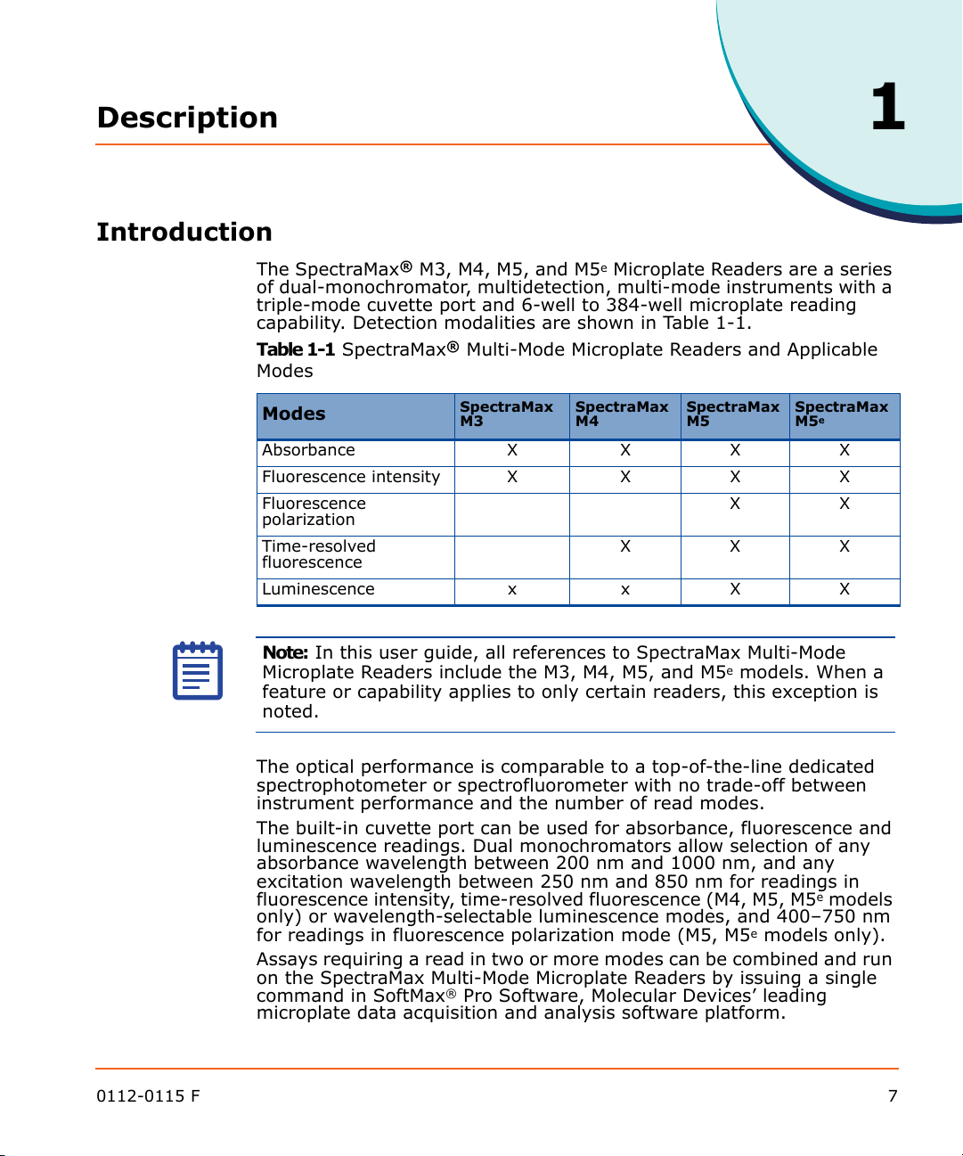
The SpectraMax® M3, M4, M5, and M5e Microplate Readers are a series
of dual-monochromator, multidetection, multi-mode instruments with a
triple-mode cuvette port and 6-well to 384-well microplate reading
capability. Detection modalities are shown in Table 1-1.
Table 1-1 SpectraMax® Multi-Mode Microplate Readers and Applicable
Modes
1
Modes
Absorbance X X X X
Fluorescence intensity X X X X
Fluorescence
polarization
Time-resolved
fluorescence
Luminescence x x X X
Note: In this user guide, all references to SpectraMax Multi-Mode
Microplate Readers include the M3, M4, M5, and M5e models. When a
feature or capability applies to only certain readers, this exception is
noted.
The optical performance is comparable to a top-of-the-line dedicated
spectrophotometer or spectrofluorometer with no trade-off between
instrument performance and the number of read modes.
The built-in cuvette port can be used for absorbance, fluorescence and
luminescence readings. Dual monochromators allow selection of any
absorbance wavelength between 200 nm and 1000 nm, and any
excitation wavelength between 250 nm and 850 nm for readings in
fluorescence intensity, time-resolved fluorescence (M4, M5, M5e models
only) or wavelength-selectable luminescence modes, and 400–750 nm
for readings in fluorescence polarization mode (M5, M5e models only).
Assays requiring a read in two or more modes can be combined and run
on the SpectraMax Multi-Mode Microplate Readers by issuing a single
command in SoftMax® Pro Software, Molecular Devices’ leading
microplate data acquisition and analysis software platform.
SpectraMax M3SpectraMax M4SpectraMax M5SpectraMax
XX
XXX
M5
e
0112-0115 F 7

Description
Applications
Endpoint, kinetic, spectrum, and multi-point well-scanning applications
combining absorbance and fluorescence in 6-well to 384-well
microplates, as well as endpoint, kinetic, and spectrum applications in
absorbance and fluorescence using cuvettes, can be run with little to no
optimization.
The extreme flexibility and high sensitivity of the SpectraMax Multi-
Mode Microplate Readers make them appropriate for applications within
the fields of biochemistry, cell biology, immunology, molecular biology,
and microbiology.
Typical applications include ELISA, nucleic acid, protein, enzymatic type
homogeneous and heterogeneous assays, microbial growth, endotoxin
testing, and pipettor calibration.
Certified SpectraMax® M5e-HTRF Readers
The SpectraMax M5e reader has the same performance specifications as
the M5 but is certified for use with Cisbio Bioassays’ HTRF
(Homogeneous Time-Resolved Fluorescence) technology. HTRF is a
proprietary time-resolved fluorescence technology that overcomes
many of the drawbacks of standard Fluorescence Resonance Energy
Transfer (FRET) techniques, such as the requirements to correct for
autofluorescence and the fluorescent contributions of unbound
fluorophores.
Optics
The use of two holographic diffraction grating monochromators allows
for individual optimization of wavelengths for both excitation and
emission in fluorescence readings. Mirrored optics focus the light into
the sample volume, and cutoff filters are used to reduce stray light and
minimize background interference. The light source is a high-powered
Xenon flash lamp. Sensitivity or read-speed can be optimized by
varying the number of lamp flashes per read.
Dynamic Range
The dynamic range of detection is from 10-6 to 10
Variations in measured fluorescence values are virtually eliminated by
internal compensation for detector sensitivity, photomultiplier tube
voltage and sensitivity, as well as excitation intensity. The photometric
range is 0–4 ODs with a resolution of 0.001 OD.
8 0112-0115 F
-12
molar fluorescein.
SpectraMax M3, M4, M5, and M5e Multi-Mode Microplate Readers
PathCheck® Pathlength Measurement Technology
A SpectraMax Multi-Mode Microplate Reader with PathCheck Pathlength
Measurement Technology allows normalization of variable well volumes
to 1-cm cuvette readings. PathCheck Pathlength Measurement
Technology allows for multichannel pipettor validation and for
experiment comparison from different days.
Automix
Using the Automix feature of the SoftMax Pro Software, the contents of
the wells in a microplate can be mixed automatically by linear shaking
before each read cycle, making it possible to perform kinetic analysis of
solid-phase, enzyme-mediated reactions (mixing is not critical for
liquid-phase reactions).
Temperature Control
Temperature in the microplate chamber is isothermal, both at ambient
and when the incubator is turned on. When the incubator is on, the
temperature may be controlled from 2°C above ambient to 60°C.
Supported Plates
Microplates having 6, 12, 24, 48, 96, and 384 wells can be used in the
SpectraMax Multi-Mode Microplate Readers. Top and bottom reads are
available for fluorescence, time-resolved fluorescence and
luminescence detection. When reading optical density at wavelengths
below 340 nm, special UV-transparent, disposable or quartz
microplates and cuvettes that allow transmission of the far UV spectra
must be used.
One plate carrier adapter is provided with the instrument. The adapter
is required for optimum performance with standard 96-well and 384-
well format microplates for all top-read applications.
0112-0115 F 9
Description
Computer Control
An external computer running SoftMax Pro Software, which provides
integrated instrument control, data display, and statistical data
analysis, controls the SpectraMax Multi-Mode Microplate Readers.
Cuvette port functionality can also be controlled using SoftMax Pro
Software.
SoftMax Pro Software provides the following functionality:
Instrument Control
SoftMax Pro Software allows you to set up and run a complete protocol
for the SpectraMax Multi-Mode Microplate Reader, as well as all other
Molecular Devices' microplate readers. Instrument settings can be
saved as a protocol file and used repeatedly for reading different
microplates or cuvettes. All stand-alone instrument functions can be
controlled using the software. In addition, SoftMax Pro Software
provides capabilities that are not available when using an instrument in
stand-alone mode such as user-defined kinetic run times, read
intervals, Automix parameters, etc.
Data Collection and Display
SoftMax Pro Software collects and stores all raw data received from the
instrument. Data is displayed in a grid format that corresponds to the
wells in a microplate or individual cuvettes.
SoftMax Pro Software can collect data from one or more microplates or
cuvettes and store it in a single data file, using the same or different
instrument settings for different microplates or cuvettes. For example,
microplates containing different samples can be read using the same or
different modes, all within the same experiment.
Data Reduction and Plotting
You can manipulate or “reduce” the raw data using dozens of built-in
formulas or define your own analysis structure to quickly and easily
summarize the raw data. More than one reduction can be shown, and
results from different microplates or cuvettes can be compared within
the same experiment.
Immediate Results Reporting and Analysis
Once you have defined instrument settings, and have customized a
SoftMax Pro Software data file with assay information, reduction
settings, custom columns in Group sections, and summary objects, you
can save this information to create an assay protocol. Protocols can be
used throughout a department or company for highly repeatable data
collection and analysis that is completed the second the plate read has
completed.
10 0112-0115 F
Reader Components
Control Panel Back PanelCuvette Chamber
Microplate Drawer
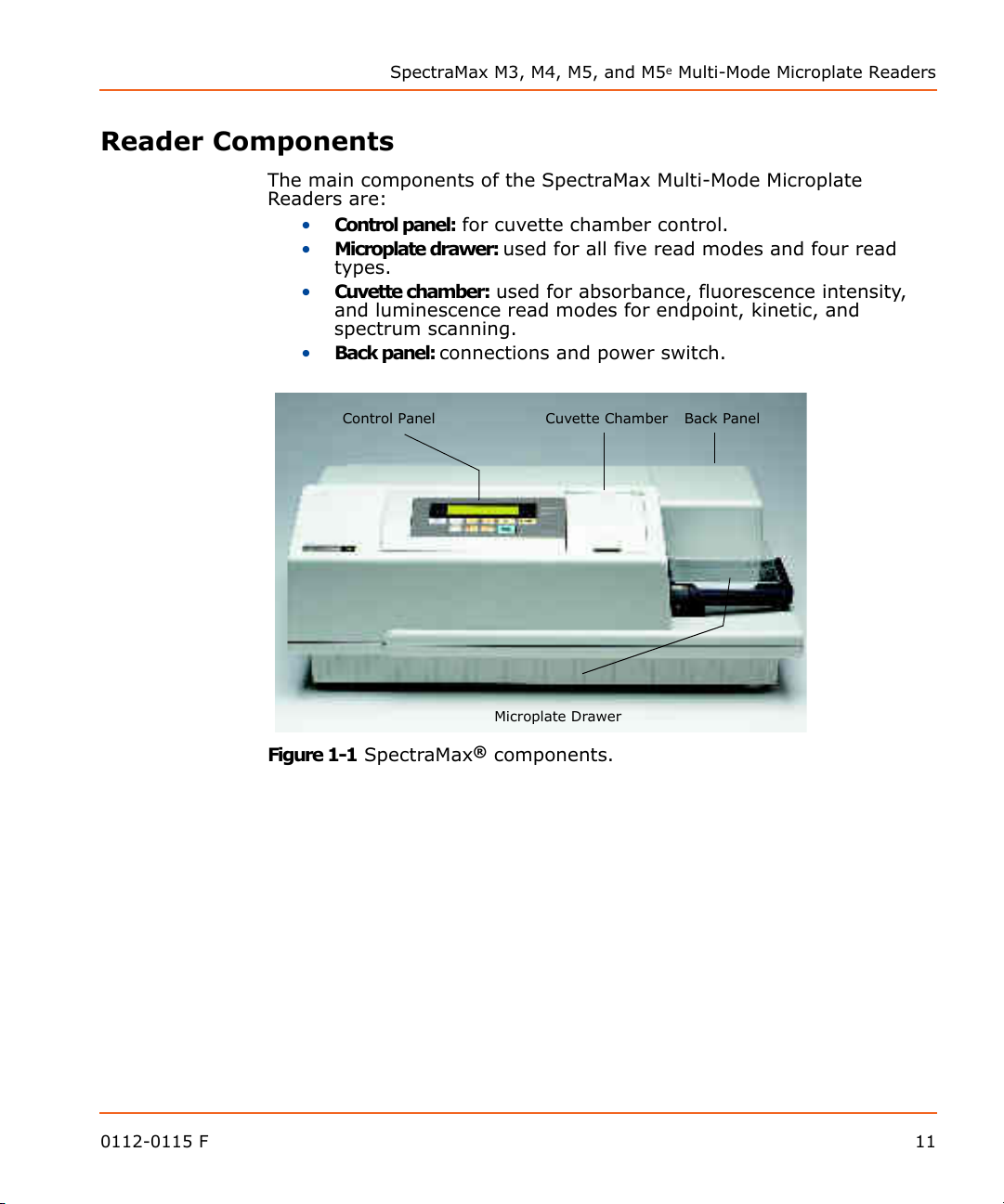
The main components of the SpectraMax Multi-Mode Microplate
Readers are:
• Control panel: for cuvette chamber control.
• Microplate drawer: used for all five read modes and four read
types.
• Cuvette chamber: used for absorbance, fluorescence intensity,
and luminescence read modes for endpoint, kinetic, and
spectrum scanning.
• Back panel: connections and power switch.
SpectraMax M3, M4, M5, and M5e Multi-Mode Microplate Readers
Figure 1-1 SpectraMax® components.
0112-0115 F 11
Description
MODE
The Control Panel
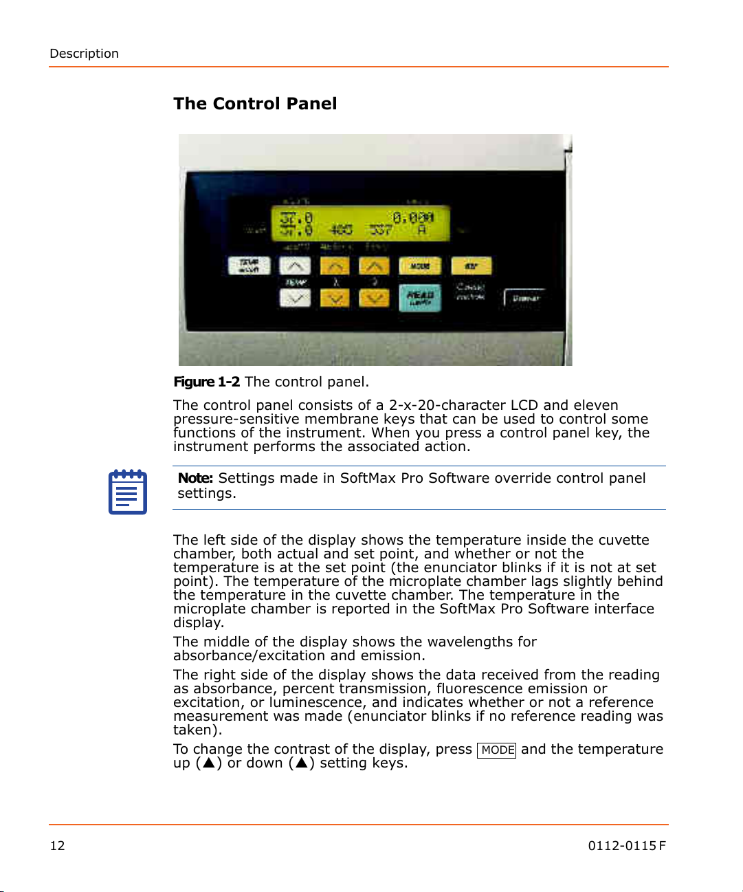
Figure 1-2 The control panel.
The control panel consists of a 2-x-20-character LCD and eleven
pressure-sensitive membrane keys that can be used to control some
functions of the instrument. When you press a control panel key, the
instrument performs the associated action.
Note: Settings made in SoftMax Pro Software override control panel
settings.
The left side of the display shows the temperature inside the cuvette
chamber, both actual and set point, and whether or not the
temperature is at the set point (the enunciator blinks if it is not at set
point). The temperature of the microplate chamber lags slightly behind
the temperature in the cuvette chamber. The temperature in the
microplate chamber is reported in the SoftMax Pro Software interface
display.
The middle of the display shows the wavelengths for
absorbance/excitation and emission.
The right side of the display shows the data received from the reading
as absorbance, percent transmission, fluorescence emission or
excitation, or luminescence, and indicates whether or not a reference
measurement was made (enunciator blinks if no reference reading was
taken).
To change the contrast of the display, press
and the temperature
up () or down () setting keys.
12 0112-0115 F

SpectraMax M3, M4, M5, and M5e Multi-Mode Microplate Readers
TEMP on/off
TEMP
Temp On/Off
The key enables and disables the incubator that controls the
temperature within both the microplate chamber and the cuvette port.
• When the incubator is on, the set temperature and actual
temperature (cuvette chamber only) are shown on the front
panel LCD display.
• When the instrument is performing a kinetic or spectral scan,
the temperature keys on the front panel are disabled.
Temp
The keys allow you to enter a set point at which to regulate the
cuvette and microplate chamber temperature. However, remember that
the cuvette temperature only is reported on the LCD display, while the
microplate chamber temperature is reported in the SoftMax Pro
Software interface display.
Pressing this key scrolls the temperature up or down, starting at the
previous temperature setting (or the default of 37.0°C, if no setting had
been made):
• Pressing the up () or down () arrow once increments or
decrements the displayed temperature by 0.1°C.
• Pressing and holding either arrow increments or decrements the
displayed temperature by 1°C until it is released.
You cannot set a temperature beyond the upper (60°C) or lower (15°C)
instrument limits.
Wavelengths ()
Selects the wavelength to be used for reading the cuvette manually.
Two s et s o f up or down arrow keys are available for setting
absorbance/excitation (fluorescence) wavelengths and emission
(fluorescence) wavelengths.
The control panel does not display the wavelength selected through the
SoftMax Pro application.
Pressing the up or down arrow key scrolls up or down through the
available wavelengths, starting at the previous setting:
• Pressing the up () or down () arrow once increments or
decrements the displayed wavelength by 1 nm.
• Pressing and holding either arrow increments or decrements the
displayed wavelength by 10 nm until it is released.
0112-0115 F 13
Description
DRAWER
Ref
A reading of buffer, water, or air taken in the cuvette that is used as I0
to calculate Absorbance or % Transmittance. If no reference reading is
taken, the instrument uses the I0 values stored in the NVRAM (non-
volatile memory) of the instrument.
This key is disabled during a computer-controlled run.
Read Cuvette
Initiates the sample reading of the cuvette.
This key is disabled during a computer-controlled run.
Mode
A toggle switch used to display cuvette data as percent transmittance
(%T), absorbance (A), relative fluorescence units (RFU), or relative
luminescence units (RLU).
Drawer
The key opens and closes (toggles) the microplate drawer.
14 0112-0115 F
SpectraMax M3, M4, M5, and M5e Multi-Mode Microplate Readers
The Microplate Drawer
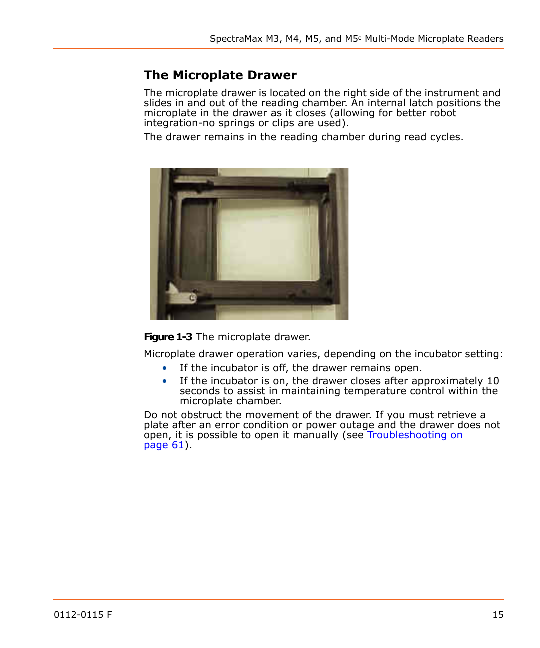
The microplate drawer is located on the right side of the instrument and
slides in and out of the reading chamber. An internal latch positions the
microplate in the drawer as it closes (allowing for better robot
integration-no springs or clips are used).
The drawer remains in the reading chamber during read cycles.
Figure 1-3 The microplate drawer.
Microplate drawer operation varies, depending on the incubator setting:
• If the incubator is off, the drawer remains open.
• If the incubator is on, the drawer closes after approximately 10
seconds to assist in maintaining temperature control within the
microplate chamber.
Do not obstruct the movement of the drawer. If you must retrieve a
plate after an error condition or power outage and the drawer does not
open, it is possible to open it manually (see
page 61
0112-0115 F 15
).
Troubleshooting on
Description
Microplates
The SpectraMax Multi-Mode Microplate Reader can accommodate SBS-
standard 6-well to 384-well microplates and strip wells. When reading
optical density at wavelengths below 340 nm, special UV-transparent,
disposable or quartz microplates allowing transmission of the deep UV
spectra must be used.
Not all manufacturers' microplates are the same with regard to design,
materials, or configuration. Temperature uniformity within the
microplate may vary depending on the type of microplate used.
Microplates currently supported by the SoftMax Pro Software for use in
this instrument are:
• 96-well Standard, 96 Costar, 96 Greiner Black, 96 Bottom
Offset, 96 Falcon, 96 BD Optilux/Biocoat, 96 BD Fluoroblok MW
Insert, 96 Corning Half Area, 96 MDC HE PS
• 384-well Standard, 384 Costar, 384 Greiner, 384 Falcon, 384
Corning, 384 MDC HE PS
• 48 Costar
• 24 Costar
• 12 Costar, 12 Falcon
• 6 Costar, 6 Falcon.
The SoftMax Pro Software plate list also includes half area and low-
volume plates. SoftMax Pro can always be used to define a new plate
type using the manufacturer's specifications for well size, spacing and
distance from the plate edge.
16 0112-0115 F

SpectraMax M3, M4, M5, and M5e Multi-Mode Microplate Readers
The Cuvette Chamber
Figure 1-4 The cuvette chamber.
Located at the right front of the SpectraMax instrument, the cuvette
chamber has a lid that lifts up, allowing you to insert or remove a
cuvette. The chamber contains springs that automatically position the
cuvette in the proper alignment for a reading. The cuvette door must
be closed before initiating a reading.
Cuvettes
The SpectraMax Multi-Mode Microplate Reader can accommodate
standard-height (45 mm), 1 cm cuvettes and 12 x 75 mm test tubes
when used with the test tube cover.
Not all manufacturers' cuvettes are the same with regard to design,
materials, or configuration. Temperature uniformity within the cuvette
may vary depending on the type of cuvette used.
Cuvettes used for absorbance readings are frosted on two sides. Be
sure to handle cuvettes on the frosted sides only. Place the cuvette into
the chamber so that the “reading” (clear) sides face left and right.
Fluorescence cuvettes are clear on all four sides and should be handled
carefully. Place a frosted cuvette into the chamber so that the “reading”
(clear) sides face left and right. Semi-Micro and Ultra-Micro cuvettes
can also be used with an adapter. See
information about supported cuvettes.
0112-0115 F 17
Cuvettes on page 78 for more
Description
Power Switch
Power Cord
Receptacle
Label
Fuse Box
Cover
Computer
Port
Printer
Port
Figure 1-5 The test tube cover.
The Back Panel
18 0112-0115 F
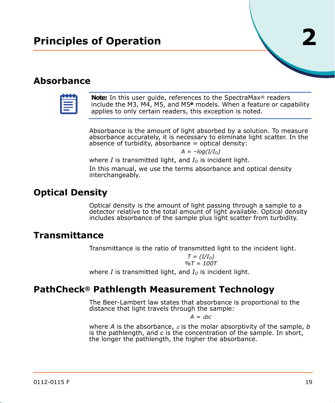
Figure 1-6 Schematic of the back panel of a reader.
The following components are located on the back panel of the
SpectraMax instrument:
• Power switch: a rocker switch, labeled I/O (for on and off,
respectively).
• Power cord receptacle: plug the power cord in here.
• Fuse box cover: cannot be opened while the power cord is
plugged in. When opened, it provides access to the fuse box
containing two fuses that are required for operation.
• Computer port (double-shielded 8-pin RS-232 serial, for use with an
external computer): plug one end of an 8-pin DIN serial cable into
this port; the other end attaches to the serial (modem) port of
the computer.
• Printer port: not used for the SpectraMax instrument
• Label: provides information about the reader, such as line
voltage rating, cautionary information, serial number, etc.
Record the serial number shown on this label for use when
contacting Molecular Devices Technical Support.
Principles of Operation
Absorbance
Note: In this user guide, references to the SpectraMax® readers
include the M3, M4, M5, and M5e models. When a feature or capability
applies to only certain readers, this exception is noted.
Absorbance is the amount of light absorbed by a solution. To measure
absorbance accurately, it is necessary to eliminate light scatter. In the
absence of turbidity, absorbance = optical density:
where I is transmitted light, and IO is incident light.
In this manual, we use the terms absorbance and optical density
interchangeably.
Optical Density
Optical density is the amount of light passing through a sample to a
detector relative to the total amount of light available. Optical density
includes absorbance of the sample plus light scatter from turbidity.
2
A = –log(I/IO)
Transmittance
Transmittance is the ratio of transmitted light to the incident light.
T = (I/IO)
%T = 100T
where I is transmitted light, and IO is incident light.
PathCheck® Pathlength Measurement Technology
The Beer-Lambert law states that absorbance is proportional to the
distance that light travels through the sample:
A =
bc
where A is the absorbance,
is the pathlength, and c is the concentration of the sample. In short,
the longer the pathlength, the higher the absorbance.
0112-0115 F 19
is the molar absorptivity of the sample, b
Principles of Operation
Horizontal
light path
Vertical light path
Cuvette Microplate wells
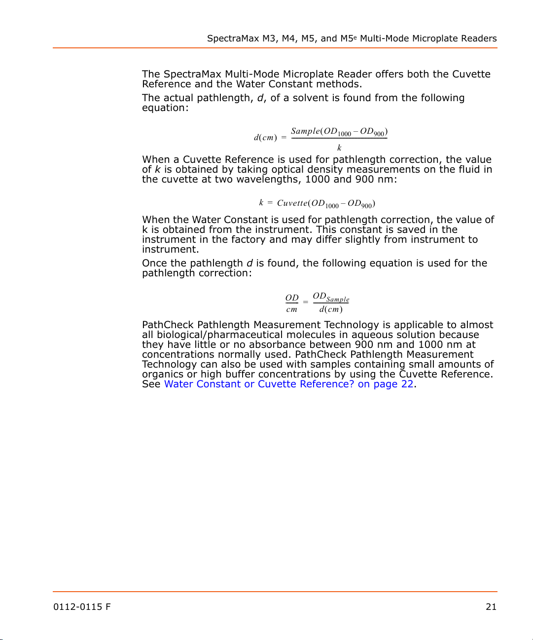
Microplate readers use a vertical light path so the distance of the light
through the sample depends on the volume. This variable pathlength
makes it difficult to perform extinction-based assays and also makes it
confusing to compare results between microplate readers and
spectrophotometers.
The standard pathlength of a cuvette is the conventional basis for
quantifying the unique absorbtivity properties of compounds in
solution. Quantitative analyses can be performed on the basis of
extinction coefficients, without standard curves (for example, NADH-
based enzyme assays). When using a cuvette, the pathlength is known
and is independent of sample volume, so absorbance is proportional to
concentration.
In a microplate, pathlength is dependent on the liquid volume, so
absorbance is proportional to both the concentration and the
pathlength of the sample. Standard curves are often used to determine
analyte concentrations in vertical-beam photometry of unknowns, yet
errors can still arise from pipetting the samples and standards. The
PathCheck
determines the pathlength of aqueous samples in the microplate and
normalizes the absorbance in each well to a pathlength of 1 cm. This
novel approach to correcting the microwell absorbance values is
accurate to within 2.5% of the values obtained directly in a 1 cm
cuvette.
®
Pathlength Measurement Technology feature automatically
Figure 2-1 Cuvette and microwell light paths.
Reference measurements made by reading the cuvette (Cuvette
Reference) or using factory-stored values derived from deionized water
(Water Constant) can be used to normalize the optical density data for
microplate wells.
Pathlength correction is accomplished only when using the PathCheck
Pathlength Measurement Technology with SoftMax
®
Pro Software.
PathCheck Pathlength Measurement Technology is patented by
Molecular Devices and can be performed only on an Molecular Devices
plate reader.
20 0112-0115 F
SpectraMax M3, M4, M5, and M5e Multi-Mode Microplate Readers
dcm
Sample OD
1000
OD
900
–
k
-----------------------------------------------------------------=
k
Cuvette OD
1000
OD
900
–
=
OD
cm
---------
OD
Sample
dcm
------------------------=
The SpectraMax Multi-Mode Microplate Reader offers both the Cuvette
Reference and the Water Constant methods.
The actual pathlength, d, of a solvent is found from the following
equation:
When a Cuvette Reference is used for pathlength correction, the value
of k is obtained by taking optical density measurements on the fluid in
the cuvette at two wavelengths, 1000 and 900 nm:
When the Water Constant is used for pathlength correction, the value of
k is obtained from the instrument. This constant is saved in the
instrument in the factory and may differ slightly from instrument to
instrument.
Once the pathlength d is found, the following equation is used for the
pathlength correction:
PathCheck Pathlength Measurement Technology is applicable to almost
all biological/pharmaceutical molecules in aqueous solution because
they have little or no absorbance between 900 nm and 1000 nm at
concentrations normally used. PathCheck Pathlength Measurement
Technology can also be used with samples containing small amounts of
organics or high buffer concentrations by using the Cuvette Reference.
See
Water Constant or Cuvette Reference? on page 22.
0112-0115 F 21

Principles of Operation
Water Constant or Cuvette Reference?
The PathCheck Pathlength Measurement is based on the absorbance of
water in the near infrared region (between 900 nm and 1000 nm). If
the sample is completely aqueous, has no turbidity and has a low salt
concentration (less than 0.5 M), the Water Constant is adequate. The
Water Constant is determined during manufacture and is stored in the
instrument.
If the sample contains an organic solvent such as ethanol or methanol,
we recommend using the cuvette reference. It is important that the
solvent does not absorb in the 900 nm to 1000 nm range (to determine
whether or not a given solvent would interfere, see the discussion of
interfering substances below). When a non-interference solvent is
added to the aqueous sample, the water absorbance decreases
proportionally to the percentage of organic solvent present. For
example, 5% ethanol decreases the water absorbance by 5% and
results in a 5% underestimation of the pathlength. You can avoid the
error by putting the same water/solvent mixture in a cuvette and using
the Cuvette Reference.
To use the Cuvette Reference, place into the cuvette port a standard
1 cm cuvette containing the aqueous/solvent mixture that is used for
the samples in the microplate. The cuvette must be in place when you
read the microplate. When you click the Read button in the SoftMax Pro
program, the instrument first makes the 900 nm and 1000 nm
measurements in the cuvette, and then makes the designated
measurements in the microplate. The cuvette values are stored
temporarily and used in the PathCheck Pathlength Measurement
Technology calculations for the microplate samples.
Use of Cuvette Reference with PathCheck Pathlength Measurement
Technology is different from a reference reading of a cuvette in a
CuvetteSet section (by clicking the Ref button in the CuvetteSet section
tool bar in the SoftMax Pro program). The cuvette reference used for
PathCheck Pathlength Measurement Technology calculations
(measurements at 900 nm and 1000 nm) does not produce data that
can be viewed in a CuvetteSet section and is used only with data in
microplates, not cuvettes.
Background Considerations
Raw optical density measurements of microplate samples include both
pathlength-dependent components (sample and solvent) and a
pathlength-independent component (OD of microplate material). The
latter must be eliminated from the PathCheck Pathlength Measurement
Technology calculation in order to obtain PathCheck Technology-
normalized results. There are 3 ways to accomplish this: plate blanks,
plate background constants, and plate pre-reads, all of which are
described in the PathCheck Pathlength Measurement Technology
section of the SoftMax Pro User Guide.
22 0112-0115 F
SpectraMax M3, M4, M5, and M5e Multi-Mode Microplate Readers
PathCheck Pathlength Measurement Technology and Interfering Substances
Any material that absorbs in the 900 nm to 1000 nm spectral region
could interfere with PathCheck Pathlength Measurement Technology
measurements. Fortunately, there are few materials that do interfere at
the concentrations typically used.
Turbidity is the most common interference: if you can detect any
turbidity in your sample, you should not use the PathCheck Technology
feature. Turbidity elevates the 900 nm measurement more than the
1000 nm measurement and causes an erroneously low estimate of
pathlength. Using Cuvette Reference does not reliably correct for
turbidity.
Samples that are highly colored in the upper visible spectrum may have
absorbance extending into the near infrared (NIR) and can interfere
with the PathCheck Pathlength Measurement Technology. Examples
include Lowry assays, molybdate-based assays and samples containing
hemoglobins or porphyrins. In general, if the sample is distinctly red or
purple, you should check for interference before using the PathCheck
Pathlength Measurement Technology.
To determine possible color interference, do the following:
• Measure the optical density at 900 nm and 1000 nm (both
measured with air reference).
• Subtract the 900 nm value from the 1000 nm value.
• Do the same for pure water.
If the delta OD for the sample differs significantly from the delta OD for
water, then it is advisable not to use the PathCheck Technology feature.
Use of Cuvette Reference does not correct for the interference with the
current calculation scheme in the SoftMax Pro program. Currently,
Cuvette Reference involves a single (automated) read at 900 nm and
1000 nm and the automated calculations in the SoftMax Pro program
do not compensate for color or solvent interference. However, you
could correct for such interference by taking two cuvette
measurements and using a different set of calculations. For further
information, contact Molecular Devices Technical Support.
Organic solvents could interfere with the PathCheck Technology feature
if they have absorbance in the region of the NIR water peak. Solvents
such as ethanol and methanol do not absorb in the NIR region, so they
do not interfere, except for causing a decrease in the water absorbance
to the extent of their presence in the solution. Their passive
interference can be avoided by using the Cuvette Reference. If,
however, the solvent absorbs between 900 and 1000 nm, the
interference would be similar to the interference of highly colored
samples described above. If you are considering adding an organic
solvent other than ethanol or methanol, you are advised to run a
spectral scan between 900 nm and 1000 nm to determine if the solvent
would interfere with the PathCheck Technology feature.
0112-0115 F 23
Principles of Operation
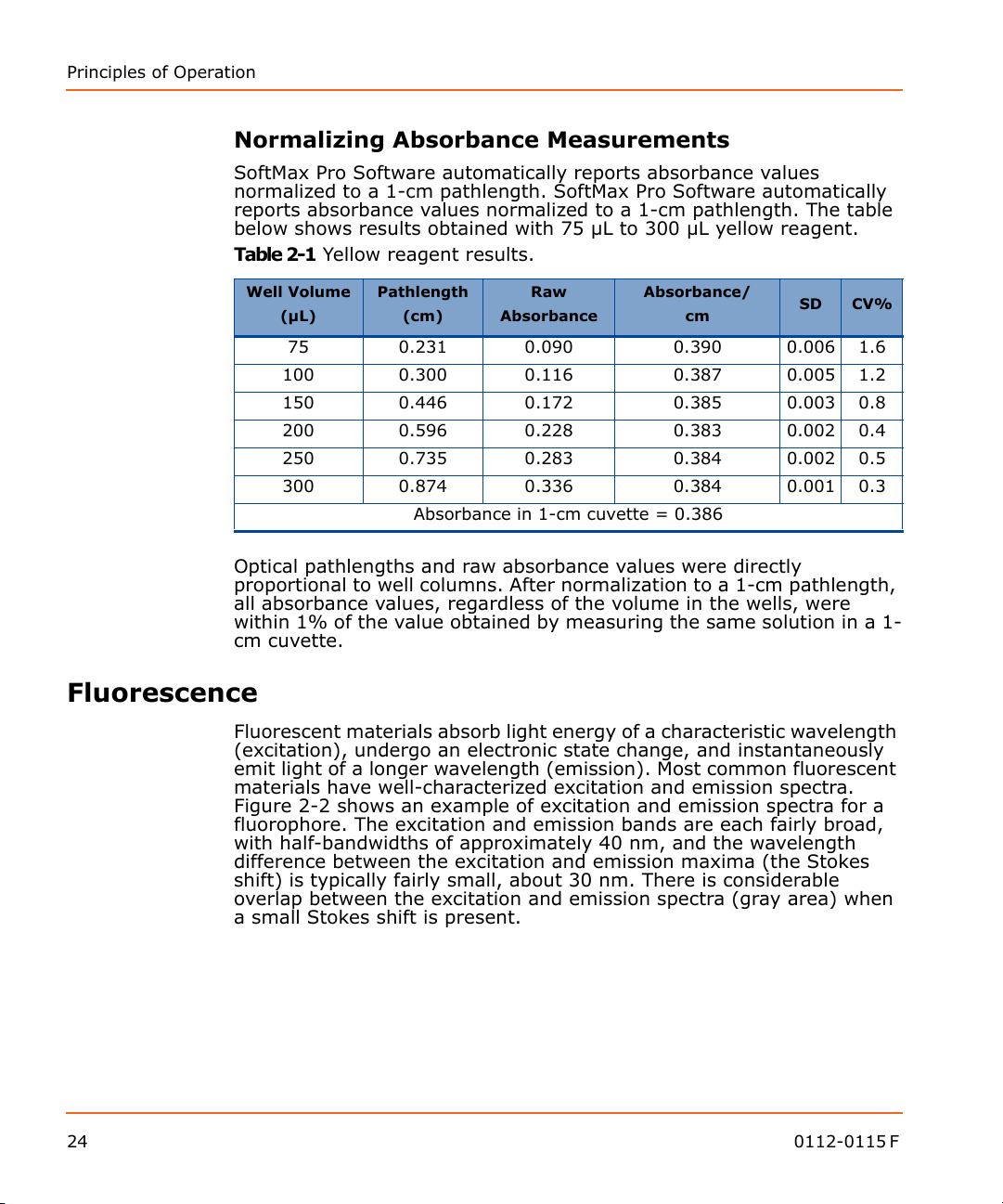
Normalizing Absorbance Measurements
SoftMax Pro Software automatically reports absorbance values
normalized to a 1-cm pathlength. SoftMax Pro Software automatically
reports absorbance values normalized to a 1-cm pathlength. The table
below shows results obtained with 75 µL to 300 µL yellow reagent.
Table 2-1 Yellow reagent results.
Well Volume
Optical pathlengths and raw absorbance values were directly
proportional to well columns. After normalization to a 1-cm pathlength,
all absorbance values, regardless of the volume in the wells, were
within 1% of the value obtained by measuring the same solution in a 1-
cm cuvette.
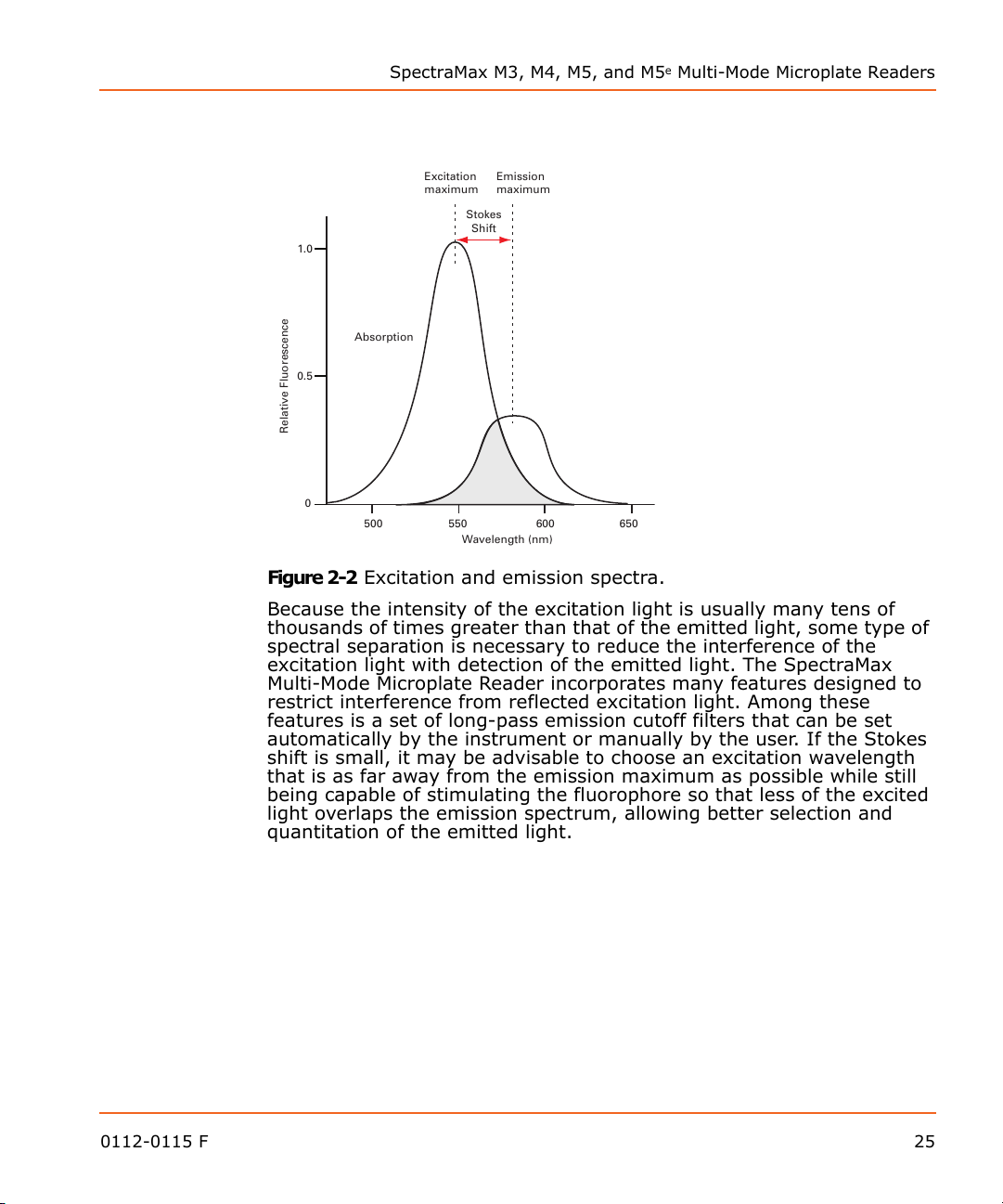
Fluorescence
Fluorescent materials absorb light energy of a characteristic wavelength
(excitation), undergo an electronic state change, and instantaneously
emit light of a longer wavelength (emission). Most common fluorescent
materials have well-characterized excitation and emission spectra.
Figure 2-2 shows an example of excitation and emission spectra for a
fluorophore. The excitation and emission bands are each fairly broad,
with half-bandwidths of approximately 40 nm, and the wavelength
difference between the excitation and emission maxima (the Stokes
shift) is typically fairly small, about 30 nm. There is considerable
overlap between the excitation and emission spectra (gray area) when
a small Stokes shift is present.
Pathlength
(µL)
75 0.231 0.090 0.390 0.006 1.6
100 0.300 0.116 0.387 0.005 1.2
150 0.446 0.172 0.385 0.003 0.8
200 0.596 0.228 0.383 0.002 0.4
250 0.735 0.283 0.384 0.002 0.5
300 0.874 0.336 0.384 0.001 0.3
(cm)
Absorbance in 1-cm cuvette = 0.386
Raw
Absorbance
Absorbance/
cm
SD CV%
24 0112-0115 F
Wavelength (nm)
Relative Fluorescence
Absorption
Excitation
maximum
Emission
maximum
Stokes
Shift
500 550 600 650
0
0.5
1.0
SpectraMax M3, M4, M5, and M5e Multi-Mode Microplate Readers
Figure 2-2 Excitation and emission spectra.
Because the intensity of the excitation light is usually many tens of
thousands of times greater than that of the emitted light, some type of
spectral separation is necessary to reduce the interference of the
excitation light with detection of the emitted light. The SpectraMax
Multi-Mode Microplate Reader incorporates many features designed to
restrict interference from reflected excitation light. Among these
features is a set of long-pass emission cutoff filters that can be set
automatically by the instrument or manually by the user. If the Stokes
shift is small, it may be advisable to choose an excitation wavelength
that is as far away from the emission maximum as possible while still
being capable of stimulating the fluorophore so that less of the excited
light overlaps the emission spectrum, allowing better selection and
quantitation of the emitted light.
0112-0115 F 25
Principles of Operation
Wavelength (nm)
Relative Fluorescence
Excitation
reading
wavelength
Emission
reading
wavelength
Fluorophore’s
excitation
maximim
Fluorophore’s
emission
maximim
500 550 600 650
0
0.5
1.0
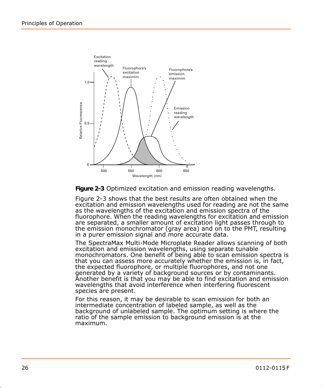
Figure 2-3 Optimized excitation and emission reading wavelengths.
Figure 2-3 shows that the best results are often obtained when the
excitation and emission wavelengths used for reading are not the same
as the wavelengths of the excitation and emission spectra of the
fluorophore. When the reading wavelengths for excitation and emission
are separated, a smaller amount of excitation light passes through to
the emission monochromator (gray area) and on to the PMT, resulting
in a purer emission signal and more accurate data.
The SpectraMax Multi-Mode Microplate Reader allows scanning of both
excitation and emission wavelengths, using separate tunable
monochromators. One benefit of being able to scan emission spectra is
that you can assess more accurately whether the emission is, in fact,
the expected fluorophore, or multiple fluorophores, and not one
generated by a variety of background sources or by contaminants.
Another benefit is that you may be able to find excitation and emission
wavelengths that avoid interference when interfering fluorescent
species are present.
For this reason, it may be desirable to scan emission for both an
intermediate concentration of labeled sample, as well as the
background of unlabeled sample. The optimum setting is where the
ratio of the sample emission to background emission is at the
maximum.
26 0112-0115 F
 Loading...