

Page 1

SpectraMax® GEMINI EM
Dual-Scanning
Microplate Spectrofluorometer
Operator’s Manual
1311 Orleans Drive
Sunnyvale, California 94089
Part # 0112-0088
Rev. A
Page 2

Molecular Devices Corporation
®
SpectraMax
GEMINI EM Operator’s Manual
Copyright
© Copyright 2002, Molecular Devices Corporation. All rights reserved. No part of this publication may
be reproduced, transmitted, transcribed, stored in a retrieval system, or translated into any language
or computer language, in any form or by any means, electronic, mechanical, magnetic, optical, chemical, manual, or otherwise, without the prior written permission of Molecular Devices Corporation,
1311 Orleans Drive, Sunnyvale, California, 94089, United States of America.
Patents
The SpectraMax GEMINI EM and methods have U.S. and International patents pending.
Trademarks
SpectraPlate and Automix are trademarks and SpectraMax and SoftMax are registered trademarks of
Molecular Devices Corporation.
Cliniplate is a registered trademark of Labsystems.
DELFIA is a registered trademark of Wallac Oy.
Emerald II is a trademark of Tropix, Inc.
All other company and product names are trademarks or registered trademarks of their respective
owners.
Disclaimer
Molecular Devices Corporation reserves the right to change its products and services at any time to
incorporate technological developments. This manual is subject to change without notice.
Although this manual has been prepared with every precaution to ensure accuracy, Molecular Devices
Corporation assumes no liability for any errors or omissions, nor for any damages resulting from the
application or use of this information.
Molecular Devices Corporation Instrument Warranty
Molecular Devices Corporation warrants this product against defects in material or workmanship as
follows:
1) All parts of the SpectraMax GEMINI EM Microplate Spectrophotometer are warranted for a
period of one (1) year from the original date of delivery.
2) All labor charges to repair the product for a period of one (1) year from the original date of
delivery will be paid by Molecular Devices Corporation.
3) This warranty covers the SpectraMax GEMINI EM instrument only and does not extend to any
computer, printer, software, reagents, or disposables used with the instrument.
ii SpectraMax GEMINI EM Operator’s Manual
Page 3

Labor and Parts
To obtain warranty service during the applicable warranty period, you must take the product or deliver the product properly packaged in the original shipping materials and carton to an authorized
Molecular Devices Corporation service facility. You must call or write to the nearest Molecular
Devices Corporation service facility to schedule warranty service. You may call Molecular Devices
Corporation at the telephone number or address below to locate the nearest service facility. You must
schedule warranty service
questing warranty service, you must present proof of purchase documentation which includes the
date of purchase, and Molecular Devices Corporation must have the enclosed Warranty Registration
form completed, signed and returned by you within ten (10) working days of the date of delivery.
This warranty covers only defects arising under normal usage and does not cover malfunctions of failures resulting from misuse, abuse, neglect, alteration, modification, or repairs by other than an authorized Molecular Devices Corporation service facility.
Repair or replacement as provided under this warranty is the exclusive remedy to the purchaser (the
“Buyer”).
or consequential damages for breach of any express or implied warranty on this product, except to the extent required by applicable law. The Seller specifically excludes all express and
implied warranties including without limitation any implied warranty that the products sold
under this agreement are merchantable or are fit for any particular purpose, except such warranties expressly identified as warranties and set forth in the Seller’s current operating manual, catalog or written guarantee covering such product. The Seller also makes no warranty
that the products sold under this agreement are delivered free of the rightful claim of any
third party by way of patent infringement or the like.
Seller, the Buyer agrees to hold the Seller harmless against any claim which arises out of compliance
with the specifications.
Molecular Devices Corporation (the “Seller”) shall not be liable for any incidental
prior
to bringing or shipping the product for servicing. At the time of re-
If the Buyer furnishes specifications to the
Any description of the products contained in this agreement is for the sole purpose of identifying
them. Any such description is not part of the basis of the bargain and does not constitute a warranty
that the products shall conform to that description. Any sample or model used in connection with this
agreement is for illustrative purposes only, is not part of the basis of the bargain, and is not to be construed as a warranty that the products will conform to the sample or model. No affirmation of fact or
promise made by the Seller, whether or not in this agreement, shall constitute a warranty that the
products will conform to the affirmation or the promise.
For the name of the nearest authorized Molecular Devices Corporation service facility please contact
Molecular Devices at one of the following telephone numbers:
(408) 747-1700
(800) 635-5577 (U.S. and Canada)
~
SpectraMax GEMINI EM Operator’s Manual iii
Page 4

iv SpectraMax GEMINI EM Operator’s Manual
Page 5

Contents
Figures . . . . . . . . . . . . . . . . . . . . . . . . . . . . . . . . . . . . . . . . vii
Tables. . . . . . . . . . . . . . . . . . . . . . . . . . . . . . . . . . . . . . . . viii
Conventions Used in this Manual . . . . . . . . . . . . . . . . . .ix
Chapter 1: Instrument Description. . . . . . . . . . . . . . . . . . . . . . 1-1
Introduction . . . . . . . . . . . . . . . . . . . . . . . . . . . . . . . . . . .1-3
Component Description . . . . . . . . . . . . . . . . . . . . . . . . .1-4
The Control Panel . . . . . . . . . . . . . . . . . . . . . . . . . . .1-4
The Microplate Drawer . . . . . . . . . . . . . . . . . . . . . .1-6
The Optical System . . . . . . . . . . . . . . . . . . . . . . . . . .1-7
The Back Panel. . . . . . . . . . . . . . . . . . . . . . . . . . . . . .1-8
Principles of Operation . . . . . . . . . . . . . . . . . . . . . . . . . .1-9
Fluorescence. . . . . . . . . . . . . . . . . . . . . . . . . . . . . . . .1-9
Luminescence. . . . . . . . . . . . . . . . . . . . . . . . . . . . . .1-11
Functional Description . . . . . . . . . . . . . . . . . . . . . . . . .1-11
Modes of Operation . . . . . . . . . . . . . . . . . . . . . . . .1-11
Temperature Regulation . . . . . . . . . . . . . . . . . . . .1-12
Automix . . . . . . . . . . . . . . . . . . . . . . . . . . . . . . . . . .1-13
Computer Control. . . . . . . . . . . . . . . . . . . . . . . . . .1-13
Specifications . . . . . . . . . . . . . . . . . . . . . . . . . . . . . . . . .1-14
Glossary of Terms . . . . . . . . . . . . . . . . . . . . . . . . . . . . .1-16
Chapter 2: Installation . . . . . . . . . . . . . . . . . . . . . . . . . . . . . . . . . 2-1
Installation Warnings . . . . . . . . . . . . . . . . . . . . . . . . . . .2-3
Installation Cautions . . . . . . . . . . . . . . . . . . . . . . . . . . . .2-3
Unpacking. . . . . . . . . . . . . . . . . . . . . . . . . . . . . . . . . . . . .2-3
Setting Up the Instrument . . . . . . . . . . . . . . . . . . . . . . .2-3
Installing the Drawer Adapter. . . . . . . . . . . . . . . . . . . .2-4
Removing the Drawer Adapter . . . . . . . . . . . . . . . . . . .2-5
Chapter 3: Operation . . . . . . . . . . . . . . . . . . . . . . . . . . . . . . . . . . 3-1
Prepare for a Reading . . . . . . . . . . . . . . . . . . . . . . . . . . .3-3
Turn the Instrument and Computer On . . . . . . . .3-3
Set the Temperature . . . . . . . . . . . . . . . . . . . . . . . . .3-3
Read the Microplate . . . . . . . . . . . . . . . . . . . . . . . . . . . .3-3
Operation Overview . . . . . . . . . . . . . . . . . . . . . . . . . . . .3-4
Optimizing Assays . . . . . . . . . . . . . . . . . . . . . . . . . . . . .3-4
Introduction . . . . . . . . . . . . . . . . . . . . . . . . . . . . . . . .3-4
Using Spectral Scanning to Optimize Excitation
and Emission Wavelengths for Fluorescence
Assays . . . . . . . . . . . . . . . . . . . . . . . . . . . . . . . . . . . . .3-5
SpectraMax GEMINI EM Operator’s Manual v
Page 6

Chapter 4: Maintenance . . . . . . . . . . . . . . . . . . . . . . . . . . . . . . . 4-1
Technical Support . . . . . . . . . . . . . . . . . . . . . . . . . . . . . .4-3
Cleaning . . . . . . . . . . . . . . . . . . . . . . . . . . . . . . . . . . . . . .4-3
Cleaning the Fan Filter . . . . . . . . . . . . . . . . . . . . . . . . . .4-4
Changing the Fuses . . . . . . . . . . . . . . . . . . . . . . . . . . . . .4-4
Installing the Drawer Adapter. . . . . . . . . . . . . . . . . . . .4-6
Removing the Drawer Adapter . . . . . . . . . . . . . . . . . . .4-7
Moving the SpectraMax GEMINI EM . . . . . . . . . . . . .4-7
Chapter 5: Troubleshooting . . . . . . . . . . . . . . . . . . . . . . . . . . . . 5-1
Error Codes and Resolutions . . . . . . . . . . . . . . . . . . . . .5-3
Opening the Drawer Manually . . . . . . . . . . . . . . . . . . .5-4
Appendix A: Cables and Accessories . . . . . . . . . . . . . . . . . . . .A-1
Cables . . . . . . . . . . . . . . . . . . . . . . . . . . . . . . . . . . . . . . . A-3
Items Available for Use with the SpectraMax
GEMINI EM . . . . . . . . . . . . . . . . . . . . . . . . . . . . . . . . . . A-3
Appendix B: Common Wavelengths for Fluorescence and
Luminescence. . . . . . . . . . . . . . . . . . . . . . . . . . . . . B-1
Fluorescence . . . . . . . . . . . . . . . . . . . . . . . . . . . . . . . . . . B-3
Luminescence . . . . . . . . . . . . . . . . . . . . . . . . . . . . . . . . . B-3
vi SpectraMax GEMINI EM Operator’s Manual
Page 7

Figures
Figure 1.1 SpectraMax GEMINI EM. . . . . . . . . . . . . . . . . . . . . 1-4
Figure 1.2 Control Panel. . . . . . . . . . . . . . . . . . . . . . . . . . . . . . . 1-4
Figure 1.3 Microplate Drawer (Shown with Adapter
Inserted) . . . . . . . . . . . . . . . . . . . . . . . . . . . . . . . . . . . 1-6
Figure 1.4 Components of the SpectraMax GEMINI EM
Optical System . . . . . . . . . . . . . . . . . . . . . . . . . . . . . 1-7
Figure 1.5 Components on the Back Panel of the
SpectraMax GEMINI EM. . . . . . . . . . . . . . . . . . . . . 1-8
Figure 1.6 Excitation and Emission Spectra . . . . . . . . . . . . . . 1-9
Figure 1.7 Optimized Excitation and Emission Reading
Wavelengths . . . . . . . . . . . . . . . . . . . . . . . . . . . . . . 1-10
Figure 2.1 View of Rear Panel . . . . . . . . . . . . . . . . . . . . . . . . . . 2-3
Figure 2.2 Adapter Inserted in Microplate Drawer.. . . . . . . . 2-4
Figure 2.3 Microplate Drawer without Adapter. . . . . . . . . . . 2-5
Figure 3.1 Plot of RFU vs. Wavelength . . . . . . . . . . . . . . . . . . 3-6
Figure 3.2 Effects of Cutoff Filters on Fluorescein . . . . . . . . . 3-8
Figure 4.1 Power Switch, Fuse Box, and Power Receptacle . 4-5
Figure 4.2 Removing the Fuse Box . . . . . . . . . . . . . . . . . . . . . . 4-5
Figure 4.3 The Fuse Box and Holder (with Fuses) Removed
from Instrument. . . . . . . . . . . . . . . . . . . . . . . . . . . . 4-6
Figure 4.4 Adapter Inserted in Microplate Drawer.. . . . . . . . 4-6
Figure 4.5 Microplate Drawer without Adapter. . . . . . . . . . . 4-7
SpectraMax GEMINI EM Operator’s Manual vii
Page 8

Tables
Table 3.1. : Emission Cutoff Filter Default Settings . . . . . . . . . 3-9
Table 5.1. : Error Codes and Resolution . . . . . . . . . . . . . . . . . . . 5-3
viii SpectraMax GEMINI EM Operator’s Manual
Page 9

Conventions
Used in this
Manual
The names of keys that appear on the SpectraMax GEMINI EM control panel
are shown in boxed Helvetica type. Example:
Italic and boldface type are used for emphasis. Examples: “Press carefully to
engage,” “
NOTE:
CAUTION:
!
WARNING:
BIOHAZARD:
Do not press down. ”
A note provides information that will help you properly execute an
action or procedure.
Indicates an action or condition that could potentially damage the instrument or one of its components or could result in loss of
data.
Indicates a situation that could result in potential injury to a
person working with the system.
Indicates a condition involving potentially infectious
biological agents requiring that proper handling precautions be
taken.
[Setup]
.
SpectraMax GEMINI EM Operator’s Manual ix
Page 10

xSpectraMax GEMINI EM Operator’s Manual
Page 11

Chapter 1: Instrument Description
Introduction . . . . . . . . . . . . . . . . . . . . . . . . .1-3
Component Description . . . . . . . . . . . . . . .1-4
The Control Panel . . . . . . . . . . . . . . . . .1-4
The Microplate Drawer. . . . . . . . . . . . .1-6
The Optical System . . . . . . . . . . . . . . . .1-7
The Back Panel . . . . . . . . . . . . . . . . . . . .1-8
Principles of Operation . . . . . . . . . . . . . . . .1-9
Fluorescence . . . . . . . . . . . . . . . . . . . . . .1-9
Luminescence. . . . . . . . . . . . . . . . . . . .1-11
Functional Description . . . . . . . . . . . . . . .1-11
Modes of Operation. . . . . . . . . . . . . . .1-11
Temperature Regulation. . . . . . . . . . .1-12
Automix . . . . . . . . . . . . . . . . . . . . . . . .1-13
Computer Control . . . . . . . . . . . . . . . .1-13
Specifications . . . . . . . . . . . . . . . . . . . . . . .1-14
Glossary of Terms . . . . . . . . . . . . . . . . . . .1-16
Page 12

Chapter 1
1-2 SpectraMax GEMINI EM Operator’s Manual
Page 13

Instrument Description
Introduction
The SpectraMax™ GEMINI EM Dual-Scanning Microplate Spectrofluorometer can perform a variety of fluorescent applications as well as some luminescent assays. The extreme flexibility and high sensitivity of the SpectraMax
GEMINI EM make it appropriate for applications within the fields of biochemistry, cell biology, immunology, molecular biology, and microbiology.
The instrument features a bottom-read mode ideal for whole-cell-based
assays and may be automatically switched to a top read mode for solutionphase measurements.
The SpectraMax GEMINI EM uses two holographic diffraction grating
monochromators which allow for individual optimization of wavelengths for
both excitation and emission. The dual-scanning capability can also be used
to determine excitation and emission settings for new fluorescent probes.
Mirrored optics focus the light into the sample volume, and cutoff filters are
used to reduce stray light and minimize background interference. The light
source is a high-powered Xenon flashlamp; additional flexibility is provided
by allowing a variable number of lamp flashes per read.
Microplates having 6, 12, 24, 48, 96, and 384 wells can be used in the
SpectraMax GEMINI EM. Top or bottom detection is available at the touch of
a button. Detection of species collected on membrane plates is also possible.
One plate carrier adapter is provided with the instrument. The adapter is
required for optimum performance with standard 96- and 384-well format
microplates when reading from the top of the microplate.
The dynamic range of detection is from 10
-6
to 10
-11
molar fluorescein. Variations in measured fluorescence values are virtually eliminated by internal
compensation for detector sensitivity, photomultiplier tube voltage and sensitivity, as well as excitation intensity.
Temperature in the microplate chamber is isothermal, both at ambient and
when the incubator is turned on. When the incubator is on, the temperature
may be controlled from 4°C above ambient to 45°C.
The contents of the wells in a microplate can be mixed automatically by shaking before each read cycle, which makes it possible to perform kinetic analysis
of solid-phase, enzyme-mediated reactions such as a kinetic ELISA.
The SpectraMax GEMINI EM is controlled by an external computer running
®
SoftMax
Pro software which provides integrated instrument control, data
display, and statistical data analysis. The SpectraMax GEMINI EM cannot be
operated without the computer and SoftMax Pro software.
SpectraMax GEMINI EM Operator’s Manual 1-3
Page 14
Chapter 1
Component Description
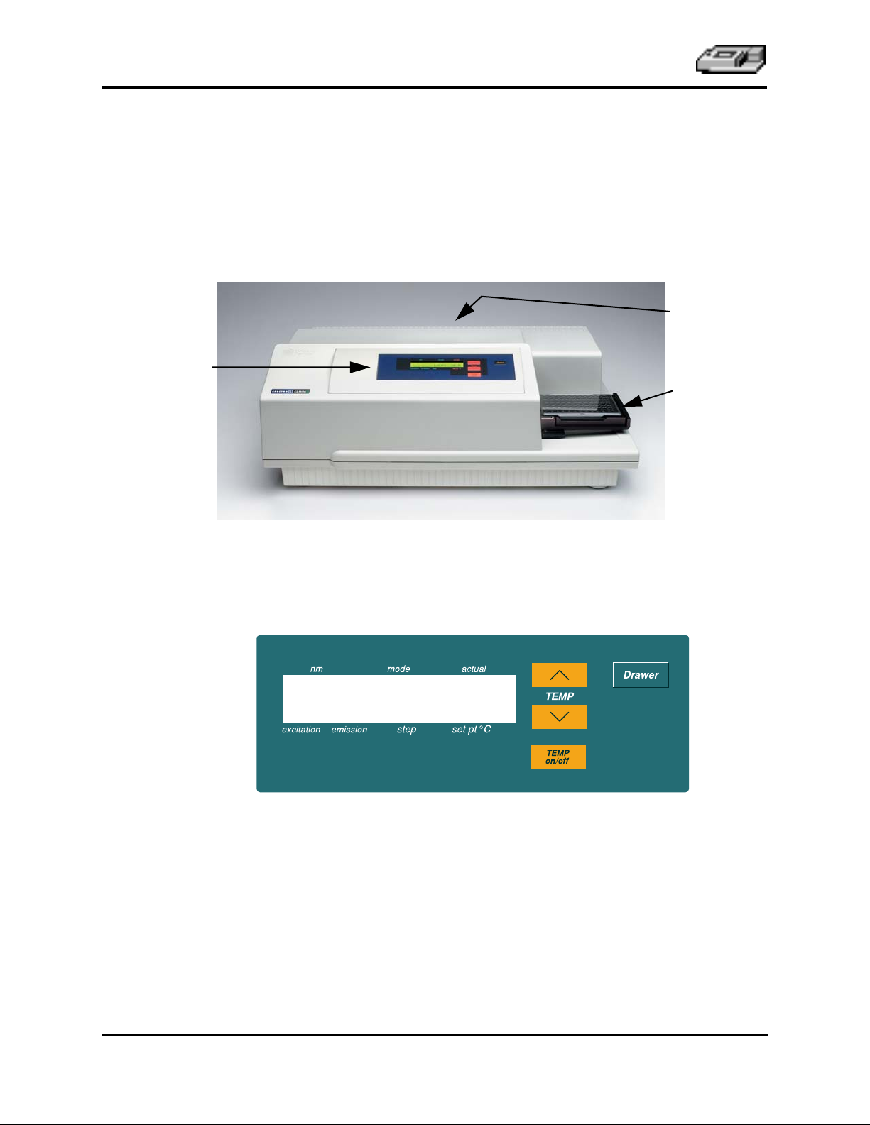
Control Panel
The main components of the SpectraMax GEMINI EM described in this
manual are:
• The control panel
• The microplate drawer
• Optical system
• The back panel (connections and power switch)
Back Panel
Microplate
Drawer
Figure 1.1: SpectraMax GEMINI EM
The Control Panel
Figure 1.2: Control Panel
The control panel consists of an LCD and four pressure-sensitive membrane
keys which can be used to initiate and regulate the temperature and to open/
close the drawer. When you press a control panel key, the SpectraMax
GEMINI EM performs the desired action.
LCD
A 2-x-20-character liquid crystal display which shows the current instrument
settings.
1-4 SpectraMax GEMINI EM Operator’s Manual
Page 15

TEMP
TEMP
on/off
Instrument Description
Keys
Allows you to enter a set point at which to regulate the microplate chamber
temperature. Pressing this key scrolls the temperature up or down, starting at
the previous temperature setting (or the default of 37.0°C, if no setting had
been made). Pressing the up (
ments the temperature shown in the display by 0.1°C; pressing and holding
ther arrow increments or decrements the temperature shown in the display by
1°C until it is released. If you increment the setting to the highest limit (45°C)
and continue to press the up (
rement the setting to the lowest limit, 15°C, and continue to press the down (
arrow, the display will not change.
Enables/disables the incubator function. When the incubator is on, the set temperature and actual temperature are shown on the front panel LCD display.
▲
) or down (
▲
) arrow, the display will not change. If you dec-
▼
) arrow once increments or decre-
ei-
▼
)
NOTE:
When the instrument is performing a kinetic or spectral scan, the
temperature keys on the front panel are disabled.
Opens or closes the microplate drawer. Whether or not the drawer will remain
open depends on the incubator setting. If the incubator is off, the drawer will
remain open; if the incubator is on, the drawer will close after approximately
10 seconds to assist in maintaining temperature control within the microplate
chamber.
NOTE:
To add reagents during a kinetic read, it is necessary to open the
drawer by pressing the
[Drawer]
key. The drawer will only open,
however, if the interval between readings is equal to the minimum
read interval originally shown by SoftMax Pro software
tional 45 seconds.
If you plan to open the drawer during a kinetic read,
plus an addi-
first determine the minimum read interval allowed and then increase
the setting by a minimum of 45 seconds. The drawer will close automatically after this interval before the next read.
SpectraMax GEMINI EM Operator’s Manual 1-5
Page 16

Chapter 1
The Microplate Drawer
Figure 1.3: Microplate Drawer (Shown with Adapter Inserted)
The microplate drawer, located on the right side of the SpectraMax
GEMINI EM, slides in and out of the microplate chamber. A small plastic
pusher, located in the front left corner of the drawer, holds the plate securely
in place when the drawer is closed. The drawer remains in the reading chamber during read cycles.
One plate carrier adapter is provided with the instrument. The adapter is
required for optimum performance with standard 96- and 384-well format
microplates in top read mode.
NOTE:
Microplate drawer operation varies, depending upon the incubator status.
When the incubator is off, the microplate drawer remains open at power up
and after a read. When the incubator is on, the drawer closes automatically to
assist in controlling the temperature of the microplate chamber. To open the
drawer, press the
mately ten seconds, after which a beeping sound will alert you approximately
two seconds before the drawer closes automatically. (The drawer will remain
open longer during intervals set for adding reagents during kinetic reads—
see the NOTE on page 1-5).
NOTE:
The adapter must be removed to read 6-, 12-, 24-, or 48-well plates.
[Drawer]
Do not obstruct the movement of the drawer. If you must retrieve a plate
after an error condition or power outage and the drawer will not open, it
is possible to open it manually (see Chapter 5, “Troubleshooting”).
key. The drawer will remain open for approxi-
Microplates
The SpectraMax GEMINI EM can accommodate standard 6-, 12-, 24-, 48-, 96-,
and 384-well microplates. Black-walled, clear-bottom or all black microplates
are generally recommended for fluorescence assays because they have lower
backgrounds than clear plates. White plates may be preferred for luminescence assays to optimize light collection.
Not all manufacturers’ microplates are the same with regard to design, materials, or configuration. Some plastics, most notably polystyrene, also have significant native fluorescence and can cause moderate to severe background
fluorescence, especially in the UV range. If high sensitivity is required, it may
be appropriate to use microplates that are designed to reduce background flu-
orescence.
1-6 SpectraMax GEMINI EM Operator’s Manual
Page 17
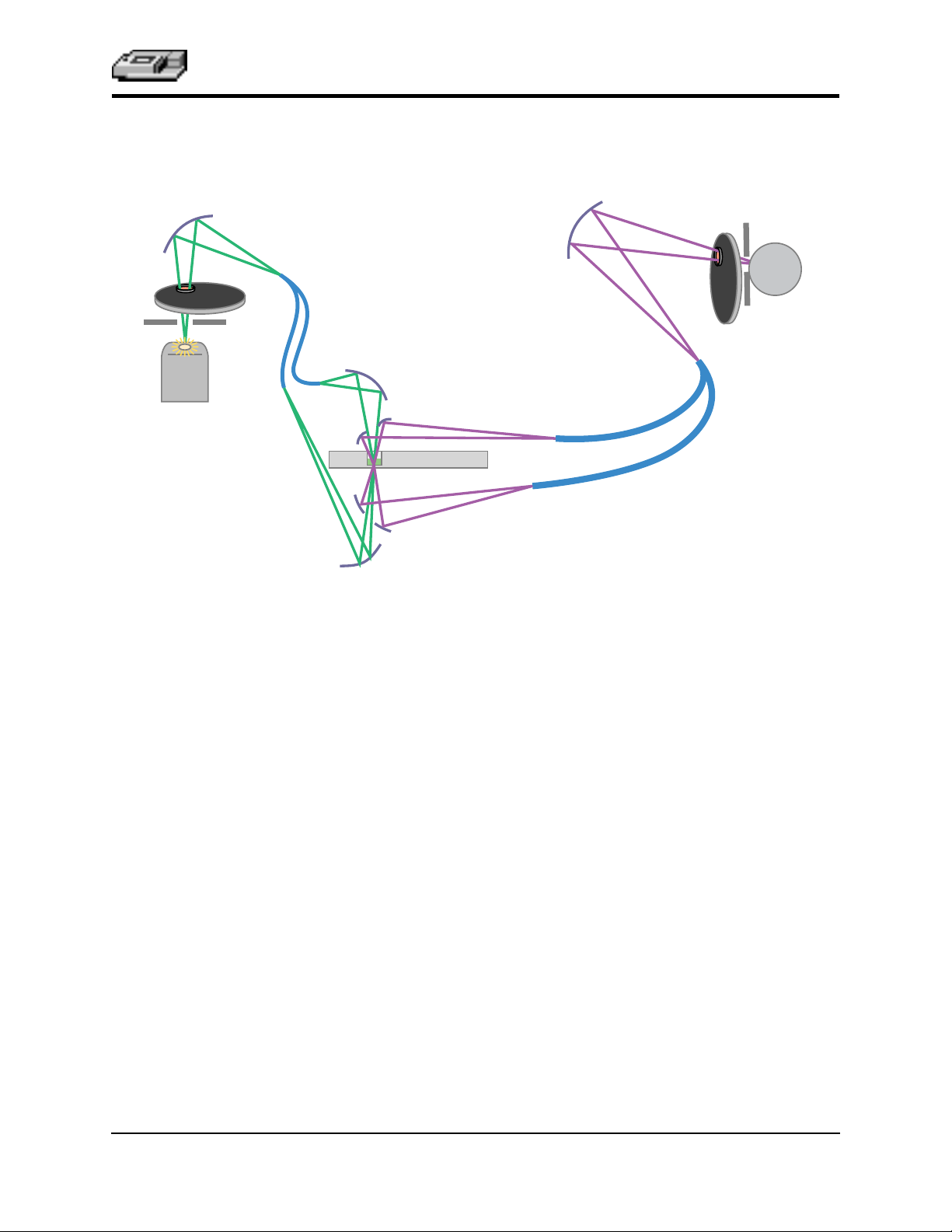
The Optical System
Instrument Description
Excitation monochromator
movable
grating
Ex
cutoff
filter
wheel
2
3
1 mm
fiber
1
flash lamp
Figure 1.4: Components of the SpectraMax GEMINI EM Optical System
Emission monochromator
movable,
focusing
grating
4
microplate
5
6
Em
7
cutoff
filter
wheel
4 mm
optical
bundles
8
photomultiplier
tube
1) The excitation light source is a xenon flashlamp. (Note that the lamp is off
when luminescence mode is selected.)
2) The light passes through a band-pass filter which reduces the amount of
stray light to the excitation monochromator.
3) The holographic diffraction grating monochromator selects the desired
excitation wavelength.
4) The excitation beam is focused by a grating to a 1.0-mm diameter fiber
into the upper or lower optics read head (selectable) before entering the
sample in the microplate well. This focusing helps to prevent part of the
beam from striking adjacent wells.
5) The light beam enters the well and, if fluorescent molecules are present,
light of the emission wavelength is emitted back out to mirrors that focus
it and send it to an optical bundle.
6) The emission monochromator (also a holographic diffraction grating
monochromator) allows light of the chosen emission wavelength to pass
to the emission filter wheel.
7) A long-pass filter further conditions the light prior to detection by the
photomultiplier tube (PMT). This filter may be set automatically by the
instrument or manually by the user.
8) The PMT detects the emitted light and passes a quantitative signal to the
instrument’s electronics which then send the data to the computer.
SpectraMax GEMINI EM Operator’s Manual 1-7
Page 18
Chapter 1
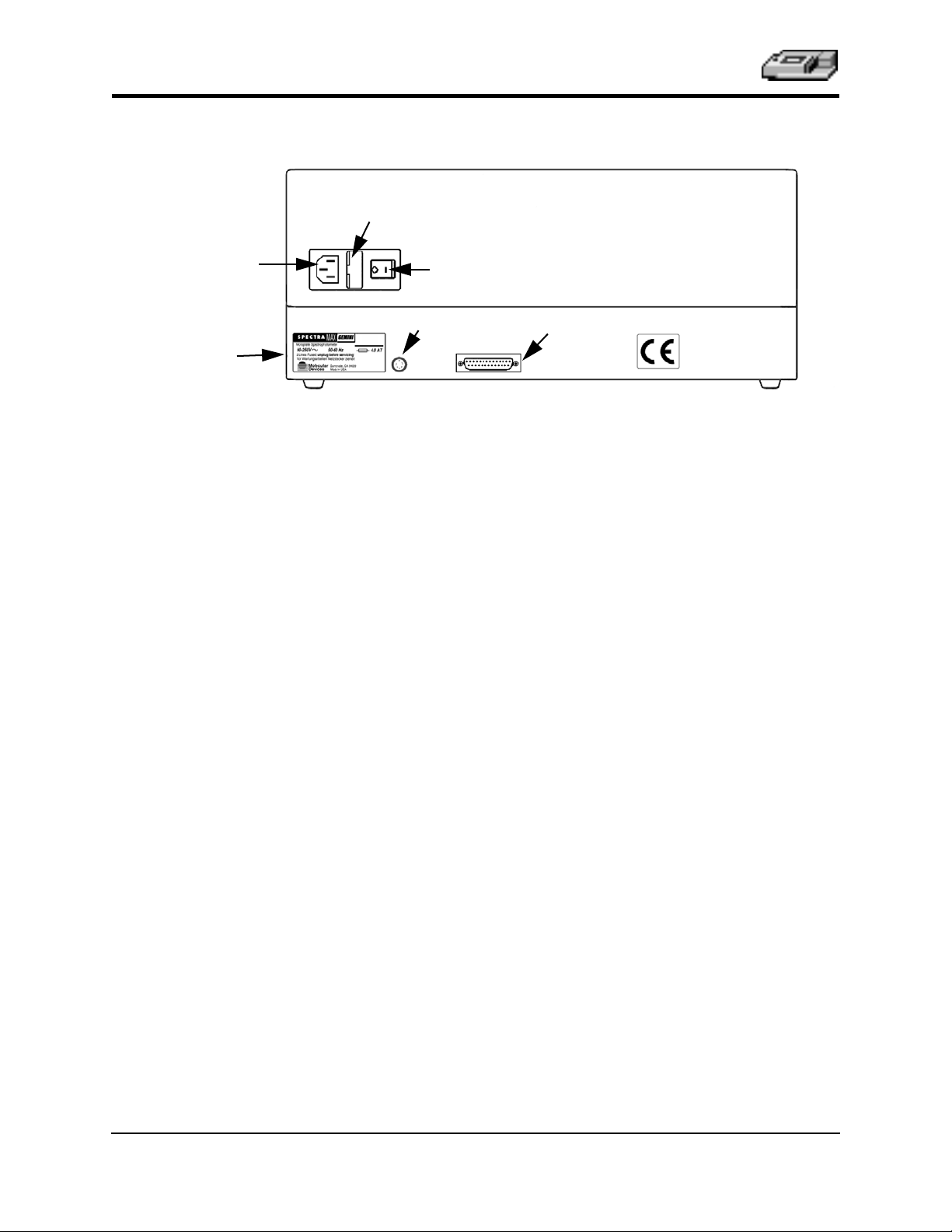
The Back Panel
Fuse Box Cover
Power Cord
Receptacle
Label
Power Switch
RS-232
Parallel Port
Serial Port
Figure 1.5: Components on the Back Panel of the SpectraMax GEMINI EM
The following components are located on the back panel of the SpectraMax
GEMINI EM:
Power switch : a rocker switch, labeled
•
Power cord receptacle : plug the power cord in here.
•
Fuse box cover : cannot be opened while the power cord is plugged in.
•
When opened, it provides access to the fuse box containing two fuses that
are required for operation.
Printer port : Present but not used in this model of SpectraMax.
•
Serial port (double-shielded RS-232, for use with an external computer):
•
plug one end of an 8-pin DIN serial cable into this port; the other end
attaches to the serial (modem) port of the computer.
Labels : provide information about the SpectraMax GEMINI EM, such as
•
line voltage rating, cautionary information, serial number, etc. Record the
serial number shown on this label for use when contacting Molecular
Devices Technical Services.
I/O
(for on and off, respectively).
1-8 SpectraMax GEMINI EM Operator’s Manual
Page 19

Instrument Description
Principles of Operation
Fluorescence
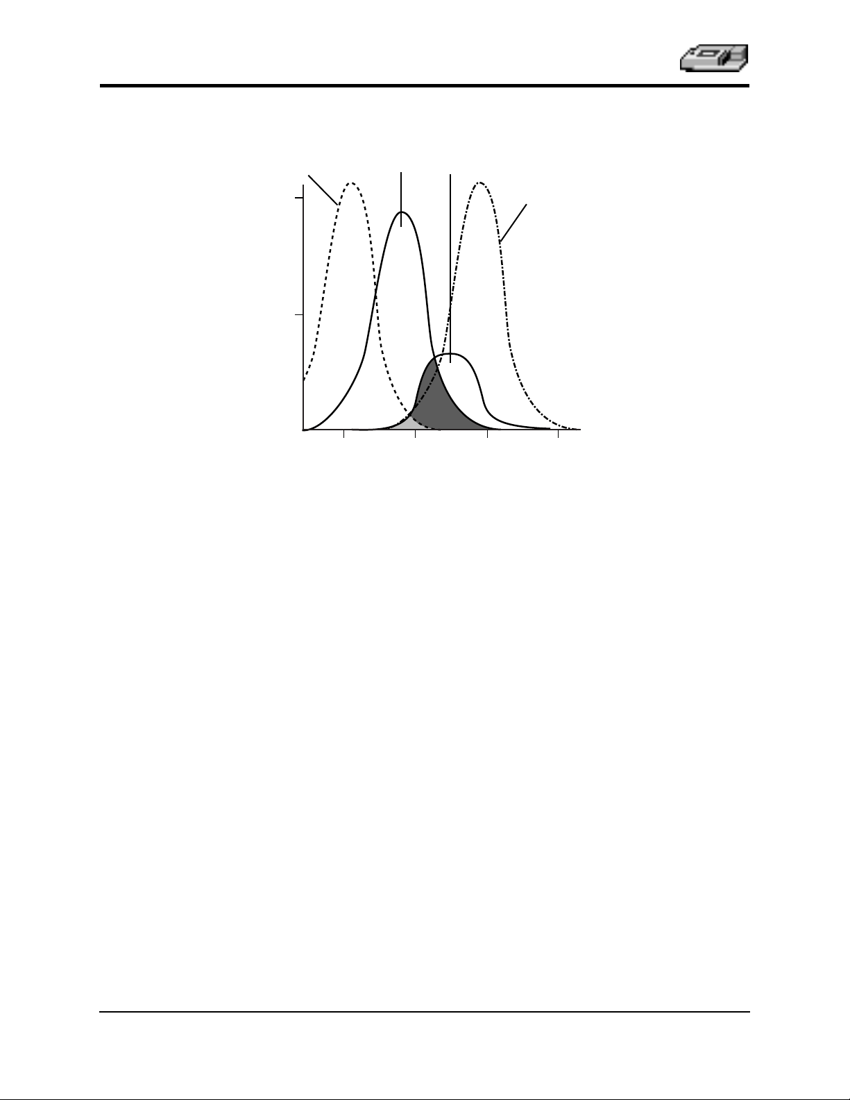
Fluorescent materials absorb light energy of a characteristic wavelength (excitation), undergo an electronic state change, and instantaneously emit light of
a longer wavelength (emission). Most common fluorescent materials have
well-characterized excitation and emission spectra. Figure 1.6 shows an example of excitation and emission spectra for a fluorophore. The excitation and
emission bands are each fairly broad, with half-bandwidths of approximately
40 nm, and the wavelength difference between the excitation and emission
maxima (the Stokes shift) is typically fairly small, about 30 nm. There is considerable overlap between the excitation and emission spectra (gray area)
when a small Stokes shift is present.
Excitation
maximum
1.0
0.5
Emission
maximum
Stokes
shift
Relative Fluorescence
0
500 550 600 650
Figure 1.6: Excitation and Emission Spectra
Because the intensity of the excitation light is usually many tens of thousands
of times greater than that of the emitted light, some type of spectral separation is necessary to reduce the interference of the excitation light with detection of the emitted light. The SpectraMax GEMINI EM incorporates many
features designed to restrict interference from reflected excitation light.
Among these features is a set of long-pass emission cutoff filters that may be
set automatically by the instrument or manually by the user. If the Stokes shift
is small, it may be advisable to choose an excitation wavelength that is as far
away from the emission maximum as possible while still being capable of
stimulating the fluorophore so that less of the excited light will overlap the
emission spectrum, allowing better selection and quantitation of the emitted
light.
Wavelength (nm)
SpectraMax GEMINI EM Operator’s Manual 1-9
Page 20
Chapter 1
Excitation
reading
wavelength
1.0
0.5
Relative Fluorescence
0
Fluorophore’s
excitation
maximum
500 550 600 650
Wavelength (nm)
Fluorophore’s
emission
maximum
Emission
reading
wavelength
Figure 1.7: Optimized Excitation and Emission Reading Wavelengths
Figure 1.7 shows that the best results are often obtained when the excitation
and emission wavelengths used for reading are not the same as the wavelengths of the excitation and emission spectra of the fluorophore. When the
reading wavelengths for excitation and emission are separated, a smaller
amount of excitation light will pass through to the emission monochromator
(gray area) and on to the PMT, resulting in a purer emission signal and more
accurate data.
The SpectraMax GEMINI EM allows scanning of both excitation and emission
wavelengths, using separate tunable monochromators. One benefit of being
able to scan emission spectra is that you can assess more accurately whether
the emission is, in fact, the expected fluorophore, or multiple fluorophores,
and not one generated by a variety of background sources or by contaminants. Another benefit is that you may be able to find excitation and emission
wavelengths that avoid interference when interfering fluorescent species are
present.
For this reason, it may be desirable to scan emission for both an intermediate
concentration of labeled sample, as well as the background of unlabeled sample. The optimum setting is where the ratio of the sample emission to background emission is at the maximum.
For more information regarding optimizing excitation and emission wavelengths using the spectral scanning capabilities of the SpectraMax GEMINI
EM, please see “Optimizing Assays” on page 3-4.
1-10 SpectraMax GEMINI EM Operator’s Manual
Page 21

Instrument Description
Luminescence
In luminescence mode, no excitation is necessary as the species being measured emit light naturally. For this reason, the lamp does not flash, so no background interference occurs. A dark estimate is done over a dark reference,
and multiple readings are averaged together into one reading per well.
You can choose the wavelength where peak emission is expected to occur. In
addition, multiple wavelength choices allow species with multiple components to be differentiated and measured easily. In luminescence read mode, no
emission cutoff filter is used. The default setting for luminescence is the “zero
order” position where the grating monochromator acts as a mirror which
reflects all light to the PMT detector.
The GEMINI EM is a microplate spectrofluorometer with photomultiplier
tube detection. Some luminescence applications, such as gene reporter assays,
may require a luminometer with photon counting detection for greater sensitivity.
Functional Description
The SpectraMax GEMINI EM is designed to be operated using SoftMax Pro
software running on a computer connected to the instrument. Stand-alone
functions are limited to setting and enabling temperature control and opening
or closing the microplate drawer.
The information contained in this section provides an overview of the instrument capabilities. For a complete description of the modes of operation, how
to choose instrument settings, etc., refer to the
SoftMax Pro User’s Manual .
Modes of Operation
The SpectraMax GEMINI EM can perform two types of readings: fluorescence
and some luminescence applications. Within each read type, the SpectraMax
GEMINI EM can perform four modes of operation: endpoint, kinetic, spectrum, and well scanning. Instrument setup parameters for each read mode are
discussed in the
Endpoint Mode
Select from one to four excitation/emission pairs in endpoint mode to obtain
fluorescent (RFU) or luminescent (RLU) readings for each well of a microplate. Endpoint data is reported as RFU or RLU.
Kinetic Mode
Kinetic analysis can be performed for up to 99 hours. The kinetic read interval
depends upon the instrument setup parameters chosen in SoftMax Pro. At the
end of a reading, the default kinetic reduction is RFU/second or RLU/second
for each well. Other kinetic reductions (e.g., milliunits/minute) are also available.
SoftMax Pro User’s Manual.
Kinetic analysis has many advantages when determining the relative activity
of an enzyme in different types of microplate assays, including ELISAs and
the purification and characterization of enzymes and enzyme conjugates.
Kinetic analysis is capable of providing improved dynamic range, precision,
and sensitivity relative to endpoint analysis.
SpectraMax GEMINI EM Operator’s Manual 1-11
Page 22

Chapter 1
∧
∨
Spectrum Mode
Spectral analysis measures fluorescence or luminescence across a spectrum of
wavelengths (minimum 250 nm; maximum 850 nm). When reading using fluorescence, you may set a fixed wavelength for excitation and scan the emission wavelengths, and vice versa. The default value reported for each well is
the wavelength of maximum fluorescence. When luminescence is chosen,
only the emission wavelengths are scanned, and the default value reported
for each well is the wavelength of maximum luminescence.
All spectrum readings are made using the scanning monochromators of the
SpectraMax GEMINI EM.
Well Scanning Mode
Some applications that involve the detection of whole cells in large-area tissue
culture plates may require the use of well scanning mode. As many cell lines
tend to grow in clumps or in the corner of microplate wells, this non-confluent growth pattern may require multiple reads in a well at different locations.
When used with 6-, 12-, 24-, 48-, or 96-well plates, well scanning allows maximum surface area detection for whole cell assays. No plate adapter is required
when using large-area tissue culture plates. For more information on well
scanning, please review the appropriate section in the
ual.
SoftMax Pro User’s Man-
Temperature Regulation
The SpectraMax GEMINI EM has been designed to regulate the temperature
of the microplate chamber from 4°C above ambient to 45°C. Upon power up,
when the incubator is off, the temperature in the SpectraMax GEMINI EM
microplate chamber is ambient and isothermal. Turning on the incubator by
pressing the
INI EM to begin warming the microplate chamber. The temperature set point
defaults to 37.0°C at start-up. With the incubator on, the temperature of
microplate chamber can be set and regulated from 4°C above ambient to 45°C.
NOTE:
[Temp on/off]
Accuracy of the temperature set point is guaranteed onlyif the set
point is at least 4°C above ambient. If the temperature set point is
lower than the ambient temperature, the chamber temperature will
remain at ambient. Temperature regulation is controlled by heaters
only and, therefore, cannot cool the temperature to a setting lower
than ambient. Additionally, the highest setting (45°C) can be achieved
only if the ambient temperature is >20°C.
(incubator) key will cause the SpectraMax GEM-
the
You can change the temperature set point by pressing the up (
(
) arrow keys until the desired set point is shown above the key in the dis-
play.
Typically, the microplate chamber will reach 37.0°C in less than 30 minutes.
The microplate chamber temperature is maintained at the set point until you
press the incubator
off.
NOTE:
1-12 SpectraMax GEMINI EM Operator’s Manual
Should you turn the incubator back on after a momentary shutdown,
allow about ten minutes for the control algorithm to fully stabilize the
microplate chamber temperature.
[Temp on/off]
key again, turning temperature regulation
) or the down
Page 23

Instrument Description
Temperature regulation and control of the microplate chamber is achieved
through electric heaters, a fan, efficient insulation, and temperature sensors.
The heaters are located in the microplate chamber which is insulated to maintain the temperature set point. The sensors are mounted inside the chamber
and measure the air temperature.
The temperature feedback closed-loop control algorithms measure the chamber air temperature, compare it to the temperature set point, and use the difference to calculate the regulation of the heating cycles. This technique results
in accurate, precise control of the microplate chamber temperature.
Automix
The Automix function permits automatic shaking of the microplate at preset
intervals, thereby mixing of the contents within each well. Automix must be
selected before beginning a reading. The actions associated with the Automix
setting depend on the read mode chosen.
For endpoint mode, enabling Automix will shake the plate for a definable
number of seconds and then read at all selected wavelengths.
When kinetic mode is chosen, two types of Automix can be enabled: you can
set Automix to shake the plate for a definable number of seconds before the
initial reading and/or for a definable number of seconds before each subsequent reading.
NOTE:
Use of Automix is strongly recommended for ELlSAs and other
solid-phase, enzyme-mediated reactions to enhance accuracy.
Computer Control
The SpectraMax GEMINI EM is equipped with an 8-pin DIN RS-232 serial
port through which the computer communicates with and controls the instrument. (Different types of cables are available for connecting to different types
of computers—see Appendix A, “Cables and Accessories.”) SoftMax Pro software, version 4.1 or greater, is required to control the SpectraMax
GEMINI EM.
SpectraMax GEMINI EM Operator’s Manual 1-13
Page 24

Chapter 1
Specifications
NOTE:
Technical specifications are subject to change without notice.
Fluorescence Photometric Performance
Wavelength range
(Excitation/Emission)
Wavelength selection Scanning monochromator tunable in 1-nm increments
Excitation wavelength bandwidth 9 nm
Emission wavelength bandwidth 9 nm
Wavelength accuracy < ± 2.0 nm
Calibration Self-calibrating with built-in fluorescence calibrators
Sensitivity
(signal 3X STD DEV of baseline)
250–850 nm
8.0 fmol/well FITC (bottom read)
3.0 fmol/well FITC (top read)
Luminescence Photometric Performance
Wavelength range 250–850 nm
Sensitivity
(signal 3X STD DEV of baseline)
10 amol/well Alkaline Phos. (obtained with Emerald II reagent from Tropix, a Perkin Elmer company)
General Photometric Performance
Microplate formats
Light source
Average lamp lifetime
Detector
Read time
Shaker
Temperature control (chamber)
Ramp up to 37°C
6, 12, 24, 48, 96, 384
Xenon flash lamp (1 joule/flash)
2 years normal operation (estimate)
Photomultiplier (R-3896)
96 wells in <15 seconds (measurement type may extend
read time)
Time 0–999 seconds
Ambient +4°C to 45°C
<20 minutes
1-14 SpectraMax GEMINI EM Operator’s Manual
Page 25

Environmental
Instrument Description
Robot ready
Turn-on time
Operating conditions
Operating humidity
Storage temperature -20 to 65°C
Operational altitude <2000 m
Installation category II
Pollution degree 2
Yes
<5 min. to rated accuracy
15 to 40°C
0 to 80% RH non-condensing
System Validation Internal standards for fluorescence and wavelength
Software Windows 95/98/NT/2000 compliant
Macintosh 8.6 – 9.x; OS X in Classic mode only
Physical
Size (h × w × d) 13.5" (340 mm) × 16.5" (420 mm) × 16.5" (420 mm)
Weight 35 lb (16 kg)
Power consumption 500 VA maximum
Line voltage and frequency 90–240 VAC, 50/60 Hz
SpectraMax GEMINI EM Operator’s Manual 1-15
Page 26

Chapter 1
Glossary of Terms
Automix
The Automix function determines how often, if at all, automated shaking of
the microplate is performed during a reading. This feature is covered by U.S.
Patent Number 5,112,134.
Emission Cutoff Filter
A long pass filter used to condition the emission light prior to detection by the
PMT. In automatic mode, the instrument sets the cutoffs automatically based
upon the wavelength(s) chosen for reading; in manual mode, you can choose
the filter wavelength manually.
Endpoint
A single reading made at one or more excitation/emission wavelengths.
Emission Spectral Scan
Measures fluorescence or luminescence across a spectrum of wavelengths for
emitted light at a fixed excitation wavelength (or no excitation in the case of
luminescence). The default value reported for each well is the wavelength of
maximum fluorescence or luminescence.
Excitation Filter
Band pass filter that reduces the amount of extraneous lamp excitation light
prior to the excitation monochromator. In endpoint reads and emission spectral scans, selection of excitation filter is automatic. In excitation spectral
scans, the user has the choice of "no excitation filter" (for smoother scans) or
"auto excitation filter" in which case there may be slight glitches in the spectrum at the wavelengths where filter changes occur.
Excitation Spectral Scan
Measures fluorescence at a single emission wavelength across a spectrum of
excitation wavelengths. The default value reported for each well is the excitation wavelength of maximum fluorescence.
Fluorescence
The light emitted by certain substances resulting from the absorption of incident radiation. To measure fluorescence accurately, it is necessary to reduce
light scatter. The governing equation for fluorescence is:
Fluorescence = extinction coefficient * concentration * quantum
yield * excitation intensity * pathlength * emission collection effi-
ciency
Fluorophore
A material which absorbs light energy of a characteristic wavelength, undergoes an electronic state change, and emits light of a longer wavelength.
Gain
The amount of increase in signal power expressed as the ratio of output to
input.
1-16 SpectraMax GEMINI EM Operator’s Manual
Page 27

Instrument Description
Incubator
Choosing Incubator from the Control menu or clicking the incubator button
opens a dialog box allowing you to start or stop temperature regulation and
to select an elevated temperature for the microplate chamber.
Instrument Setup
(In SoftMax Pro software) Defines the parameters (mode, wavelengths, automatic mixing, run time, read interval, etc.) used to read the microplate.
Kinetic
During kinetic readings, data is collected over time, with multiple readings
made at regular intervals. The values calculated based on raw kinetic data are
Vmax, Time to Vmax, and Onset Time. Kinetic readings can be single- or multiple-wavelength readings.
LCD (Liquid Crystal Display)
A 2-×-20-character display which shows the current instrument settings.
Luminescence
The emission of light by processes that derive energy from essentially nonthermal changes, the motion of subatomic particles, or the excitation of an
atomic system by radiation.
Parallel Port (Windows)
A connection on a computer, usually LPT1, where you plug in the cable for a
parallel printer. Windows supports parallel ports LPT1 through LPT3.
Photomultiplier Tube (PMT)
A vacuum tube that detects light especially from dim sources through the use
of photoemission and successive instances of secondary emission to produce
enough electrons to generate a useful current.
Read Mode
The method used to read the microplate: endpoint, kinetic, spectrum, or well
scan.
Read Type
The type of reading performed: fluorescence or luminescence.
Readings per Well
The number of times (user-definable) that readings are taken on a well in fluo-
rescence mode or the amount of time that data is collected using the luminescence read type.
SoftMax Pro
An integrated software program (from Molecular Devices Corporation) that is
used to control and collect data from the SpectraMax GEMINI EM instrument.
Stokes Shift
The difference between the wavelengths of the excitation and emission peaks.
SpectraMax GEMINI EM Operator’s Manual 1-17
Page 28

Chapter 1
1-18 SpectraMax GEMINI EM Operator’s Manual
Page 29

Chapter 2: Installation
Installation Warnings. . . . . . . . . . . . . . . . . . . 2-3
Installation Cautions . . . . . . . . . . . . . . . . . . . 2-3
Unpacking . . . . . . . . . . . . . . . . . . . . . . . . . . . . 2-3
Setting Up the Instrument. . . . . . . . . . . . . . . 2-3
Installing the Drawer Adapter . . . . . . . . . . . 2-4
Removing the Drawer Adapter . . . . . . . . . . 2-5
Page 30

Chapter 2
2-2 SpectraMax GEMINI EM Operator’s Manual
Page 31

Installation
Installation Warnings
Installation Cautions
1) Always make sure the power switch on the instrument is in the OFF position and remove the power cord from the back of the instrument prior to
any installation or relocation of the instrument.
2) Do not operate the instrument in an environment where potentially damaging liquids or gases are present.
Do not touch or loosen any screws or parts other than those specifically designated in the instructions. Doing so might cause misalignment and will void the
instrument warranty.
Unpacking The SpectraMax GEMINI EM is packed in a specially designed carton. Please
retain the carton and the packing materials. If the unit should need to be
returned for repair, you must use the original packing materials and carton
for shipping. If the carton has been damaged in transit, it is particularly
important that you retain it for inspection by the carrier in case there has also been
damage to the instrument.
WARNING:
pounds (16 kg) and should be lifted with care. It is recommended that
two persons lift the instrument together, taking the proper precautions to avoid injury.
After examining the carton, place it on a flat surface in the upright position.
Open the top of the box and lift the SpectraMax GEMINI EM, along with the
packing materials around the ends, up and out of the shipping box. Remove
the packing material from both ends of the instrument and set the instrument
down carefully. The packing list that accompanies the instrument describes all
components that should have been placed in the packing carton. Make sure
all these items are present before proceeding.
The SpectraMax GEMINI EM weighs approximately 35
Setting Up the Instrument
Power Cord
Receptacle
Label
SpectraMax GEMINI EM Operator’s Manual 2-3
1) Place the SpectraMax GEMINI EM on a level surface, away from direct sun-
light, dust, drafts, vibration, and moisture.
2) Turn the instrument around so that the back of the instrument is facing
you as shown in Figure 2.1.
Fuse Box Cover
Power Switch
RS-232
Serial Port
Figure 2.1: View of Rear Panel
Parallel Port (not currently active)
Page 32

Chapter 2
3) Insert the female end of the power cord into the power receptacle at the
rear of the SpectraMax GEMINI EM. Connect the male end to a grounded
power outlet of the appropriate voltage. Molecular Devices recommends
that you use a surge protector between the power cord and the grounded
power outlet.
4) Insert the 8-pin DIN round end of the computer connection cord into the
RS-232 serial port receptacle on the back panel of the instrument. Attach
the other end to your computer (see Appendix A for more information).
5) Turn the SpectraMax GEMINI EM around so that the control panel now
faces you. Be sure no cables run beneath the instrument. Leave at least
three inches between the back of the instrument and the nearest objects or
surfaces to ensure proper ventilation and cooling.
Installing the Drawer Adapter
If you are reading standard 96-well or 384-well microplates from the top, you
will need to install the drawer adapter.
CAUTION:
!
damage to the microplate drawer of the SpectraMax GEMINI EM. The
corner cut-out must be in the lower left corner where the plate pusher
is located.
1) Turn power to the instrument on.
2) Press the
command in SoftMax Pro software.
3) Hold the adapter so that the label is on the front side facing up.
4) Place the top back (Row A) portion of the adapter into the drawer first.
The corner cut-out must be in the lower left corner where the plate pusher
is located. While pushing against the back edge of the adapter, lower the
front of the adapter into the drawer (see Figure 2.2).
Incorrect insertion or removal of the adapter may cause
[Drawer] button on the front panel or activate the drawer open
Figure 2.2: Adapter Inserted in Microplate Drawer
2-4 SpectraMax GEMINI EM Operator’s Manual
Page 33

Installation
Removing the Drawer Adapter
If the adapter is in the drawer and you are either reading from the bottom or
using “high profile” (6-, 12-, 24-, or 48-well) plates, you will need to remove
the adapter.
CAUTION:
!
age to the microplate drawer of the SpectraMax GEMINI EM.
1) Turn power to the instrument on.
2) Press the
command in SoftMax Pro software.
Incorrect insertion or removal of the adapter may cause dam-
[Drawer] button on the front panel or activate the drawer open
Figure 2.3: Microplate Drawer without Adapter
3) Remove the adapter plate.
SpectraMax GEMINI EM Operator’s Manual 2-5
Page 34

Chapter 2
2-6 SpectraMax GEMINI EM Operator’s Manual
Page 35

Chapter 3: Operation
Prepare for a Reading. . . . . . . . . . . . . . . . . . . 3-3
Turn the Instrument and Computer On 3-3
Set the Temperature . . . . . . . . . . . . . . . . 3-3
Read the Microplate . . . . . . . . . . . . . . . . . . . . 3-3
Operation Overview. . . . . . . . . . . . . . . . . . . . 3-4
Optimizing Assays . . . . . . . . . . . . . . . . . . . . . 3-4
Introduction . . . . . . . . . . . . . . . . . . . . . . . 3-4
Using Spectral Scanning to Optimize
Excitation and Emission Wavelengths
for Fluorescence Assays . . . . . . . . . . . . . 3-5
Page 36

Chapter 3
3-2 SpectraMax GEMINI EM Operator’s Manual
Page 37

Operation
This chapter contains operating information for the SpectraMax GEMINI EM DualScanning Microplate Fluorometer. If you are an experienced user of this instrument, a
quick review of the operating steps may be found on page 3-4.
Prepare for a Reading
Turn the Instrument and Computer On
The power switch for the SpectraMax GEMINI EM is located on the back
panel. Press the rocker switch to the on position. The instrument will automatically perform diagnostic checks to ensure that it is functioning correctly.
Turn the computer on at this time also and start the SoftMax Pro software program.
Set the Temperature
If elevated temperature within the microplate chamber is desired, you should
turn on the incubator first, allowing enough time for the temperature to reach
the set point before performing a reading. When you first turn the instrument
on, up to 60 minutes may be required for the temperature within the chamber
to reach the set point. Turning on the incubator and choosing a temperature
set point can be done using the software or the front panel of the instrument
(described here).
NOTE:
To enable the incubator, press the incubator
play will indicate that temperature control is on and will show the set point
and current temperature of the microplate chamber.
To change the temperature set point, press the up or down arrow keys until
the desired temperature set point is shown in the display.
Temperature cannot be regulated at a set point that is lower than 4°C
above the ambient temperature.
[Temp on/off] key. The LCD dis-
Read the Microplate
The microplate chamber temperature will be maintained at the set point until
you disable temperature control by touching the incubator key again. When
the incubator is off, the temperature within the microplate chamber will begin
returning to ambient.
NOTE:
The underside of the microplate must be dry prior to plac-
Insert the filled microplate into the drawer, matching well A1 with position
A1 in the drawer. Make sure the microplate is flat against the drawer bottom
(for 6-, 12-, 24-, or 48-well microplates) or against the adapter (if using top
read for 96- or 386-well plates—see “Installing the Drawer Adapter” on
page 2-4 for more information).
You must use SoftMax Pro software running on a computer (properly connected to the SpectraMax GEMINI EM) in order to perform instrument setup
or reading and to analyze the data that is collected.
Should you turn the incubator back on after a momentary shutdown,
allow about ten minutes for the control algorithm to fully stabilize the
microplate chamber temperature.
BIOHAZARD:
ing it in the drawer. If the microplate has fluid on the underside, dry
it using a paper towel (or equivalent) before placing it in the drawer.
SpectraMax GEMINI EM Operator’s Manual 3-3
Page 38

Chapter 3
When reading is complete, the drawer of the instrument will open, allowing
you to remove the microplate. If the incubator is on, the drawer will close
again after approximately 10 seconds. If you return to the SpectraMax GEMINI EM and find the drawer closed after a reading has finished, press the
[Drawer] key. When the drawer opens, you may remove the microplate.
Operation Overview
Optimizing Assays
The following steps provide a quick reminder of the basic operating procedures required to perform an assay using the SpectraMax GEMINI EM.
1) Turn on the power switch of the SpectraMax GEMINI EM (located on the
back panel). The microplate drawer will open automatically.
2) If you wish to regulate the temperature inside the microplate chamber,
touch the
bring the microplate chamber to the default temperature of 37.0°C. The
microplate drawer will close.
3) If the incubator is on, the LCD will show the current temperature along
with the temperature set point. To change the set point (to any setting
from ambient +4° to 45°C), press the up or down arrow keys.
4) Select the desired instrument settings (read mode, type of analysis, template, etc.) using SoftMax Pro software on the external computer.
5) If you are performing kinetic analysis, add substrate at this time.
6) Load the prepared microplate into the drawer, being sure to match well
A1 with the A1 mark on upper left-hand corner of the drawer.
7) Using SoftMax Pro, start the reading.
[Temp on/off] (incubator) key to turn the incubator on and
Introduction
The optimum instrument settings for detection of a particular fluorophore
depend on a number of different factors. Settings that can be adjusted for
assay optimization include the excitation and emission wavelengths, emission cutoff filter, readings per well, the PMT voltage, and the temperature of
the reading chamber.
• The excitation and emission wavelengths may be set in 1-nm increments
within the range of the instrument (250-850 nm). A procedure to optimize
excitation and emission wavelengths for a given assay is outlined in the
next section.
• The 15 emission cutoff filters assist in reducing background. Sources of
background include stray excitation light and native fluorescence of plate
materials, sample constituents, and solvents (including water). The default
setting allows the instrument and SoftMax Pro software to determine which
cutoff filter should be used (see Table 3.1 for default settings) in endpoint
and kinetic modes. The spectral scan mode default uses no cutoff filter.
• The number of readings per well may vary between 1 (used for a quick estimate) and 30 (for very precise measurements). The default number of readings per well varies with the read mode: for fluorescence, the default is 6,
and for luminescence, the default is 30.
• The voltage of the photomultiplier tube may be set to low (for higher con-
3-4 SpectraMax GEMINI EM Operator’s Manual
Page 39

Operation
centration samples), medium, or high (for lower concentration samples) in
all read modes. In endpoint and spectrum mode, there is an additional setting, automatic, in which the instrument will automatically adjust the PMT
voltage for varying concentrations of sample in the plate.
• The chamber of the SpectraMax GEMINI EM is isothermal at ambient as
well as at elevated temperatures. The temperature in the reading chamber
may be adjusted from 4°C above ambient to 45°C.
Other important factors that are independent of the instrument but which
affect assay optimization include the Stokes shift. When the Stokes’ shift is
very small, optimizing the excitation and emission wavelengths and correct
cutoff filter choices are very important.
Using Spectral Scanning to Optimize Excitation and
Emission Wavelengths for Fluorescence Assays
1) Put 200 µL of sample that includes the fluorophore and 200 µL of a buffer
control into separate wells of a microplate.
2) Excitation Scan
A) Using SoftMax Pro, set up a plate section for a fluorescence read, spec-
trum mode, Em Fixed/Ex Scan, with no cutoff filter (default), and
medium PMT.
B) Set the emission wavelength based on the tentative value from the lit-
erature (or from a customary filter set used to measure your fluorophore). If the emission wavelength is not known, select a tentative
emission wavelength about 50 nanometers greater than the absorbance maximum of the fluorophore. If necessary, the absorbance maximum can be determined by performing a spectral scan in a UV/Vis
spectrophotometer.
C) Set the excitation scan to start/stop approximately 50 nm below/
above the tentative excitation value obtained from the literature
(or the customary excitation filter).
D) Set the step increment to 1 or 2 nm. (You may choose to do a prelimi-
nary scan with a 10-nm increment to determine the approximate peak
location, and then repeat the scan over a narrower wavelength range
with a 1- or 2-nm increment.)
E) Perform the scan and view the results as a plot of emission fluores-
cence vs. excitation wavelength. Note the excitation wavelength at the
emission peak and the maximum RFU value.
NOTE:
If an error message reporting missing datapoints occurs, it may be
due to possible saturation reported by SoftMax Pro at the end of the
spectral scan. Reset the PMT to “low” and rescan the sample (scan the
buffer blank with the PMT set to “medium” or “high”). If the error
occurs after scanning with the PMT set to “low,” it may be necessary
to dilute the sample.
SpectraMax GEMINI EM Operator’s Manual 3-5
Page 40

Chapter 3
NOTE:
If the excitation scan shows no apparent peak, change the PMT setting
to “high” and rescan the sample. If the spectral scan still shows no
apparent peak, adjust the Y-scale of the zoom plot so that the plot fills
the graph.
F) Select the optimal excitation wavelength. If the excitation peak wave-
length and emission wavelength are separated by more than 80 nm,
use the excitation peak wavelength value. If the excitation and emission wavelengths are less than 80 nm apart, use the shortest excitation
wavelength that gives 90% maximal emission. (Follow the plot to the
left of the peak until the RFU value falls to approximately 90% of the
maximum, and then drop a line from the 90% point on the plot to the
x-axis—see Figure 3.1.)
λ max
Max RFU
90% of
max RFU
λ at 90% of
RFU
max RFU
Wavelength
Figure 3.1: Plot of RFU vs. Wavelength
3) Emission Scan #1
A) In SoftMax Pro, set up a second plate section for a fluorescence read,
spectrum mode, Ex Fixed/Em Scan, with no cutoff filter (default), and
medium PMT.
B) Set the excitation wavelength to the value determined in 2F above.
C) Set the emission scan to start/stop approximately 50 nm below or
above the tentative emission value obtained from the literature
(or existing filter pair). Note: If the Stokes shift is less than 50 nm, then
start the emission scan above the excitation wavelength.
D) Set the step increment to 1-2 nm (or do a preliminary scan with a
10-nm increment to determine the approximate peak location and
then repeat the scan over a narrower wavelength range using a 1-2 nm
increment.)
E) Perform the scan and view the results as a plot of fluorescence vs.
emission wavelength.
4) Select an emission cutoff filter that will block as much of the residual excitation light as possible without unduly reducing the fluorescence signal.
The cutoff wavelength choices are 325, 420, 435, 475, 495, 515, 530, 550,
570, 590, 610, 630, 665, or 695 nm. The cutoff value should be near the
maximum emission wavelength (preferably between the excitation wavelength and the maximal emission wavelength) but at least 35 nm greater
than the excitation wavelength.
3-6 SpectraMax GEMINI EM Operator’s Manual
Page 41

Operation
5) Emission Scan #2
A) In SoftMax Pro, set up a third plate section for an emission scan as
specified in Step 3 above, except selecting Manual Cutoff Filter and
setting the wavelength to that determined in Step 4.
B) Perform the scan and view the results as a plot of fluorescence vs.
emission wavelength. Note the wavelength giving the maximum
emission (the optimal emission wavelength).
C) Compare the spectra of the sample containing the fluorophore to the
spectra of the buffer blank to get an estimate of the signal-to-noise
ratio. If there is significant background interference, repeat steps 5A
and 5B with another choice of cutoff filter.
6) Results: The optimal excitation and emission wavelengths are those determined in steps 2F and 5B, above.
7) Comments
A) In endpoint or kinetic fluorescence modes, the “Autofilter” feature
will generally select the same cutoff filter wavelength as will the
above optimization method. If desired, however, you may specify the
cutoff filters manually.
B) For emission wavelengths less than 325 nanometers, experimental
iteration is usually the best method of determining the optimal emission and excitation wavelengths. Begin optimization by performing
steps 1–4 above. Try emission and excitation wavelength combinations with the 325 cutoff or with no cutoff filter. Similarly, for excitation wavelengths greater than 660 nanometers, try emission and
excitation wavelength combinations with the 695 cutoff or with no
cutoff filter.
Figure 3.2 shows the effects of different cutoff filters on a scan of fluorescein
where excitation was fixed at 485 nm and emission was scanned from 490 nm
to 560 nm (buffer blanks are not shown in this plot). Table 3.1 following lists
default settings for the emission cutoff filters.
SpectraMax GEMINI EM Operator’s Manual 3-7
Page 42

Chapter 3
Figure 3.2: Effects of Cutoff Filters on Fluorescein. Emission was scanned from
490 to 560 nm; excitation was fixed at 485 nm.
3-8 SpectraMax GEMINI EM Operator’s Manual
Page 43

Table 3.1: Emission Cutoff Filter Default Settings
Automatic
Cutoff
Selection
Endpoint and Kinetic Modes
l (nm) Emission l (nm)
None <322
325 322 - 414
420 415 - 434
435 435 - 454
455 455 - 474
475 475 - 494
495 495 - 514
515 515 - 529
530 530 - 549
550 550 - 569
570 570 - 589
590 590 - 609
610 610 - 629
630 630 - 664
665 665 - 694
695 695 - 850
Note: For spectrum mode, the default is "manual"
automatic cutoff).
(no
Operation
SpectraMax GEMINI EM Operator’s Manual 3-9
Page 44

Chapter 3
3-10 SpectraMax GEMINI EM Operator’s Manual
Page 45

Chapter 4: Maintenance
Technical Support. . . . . . . . . . . . . . . . . . . . . . 4-3
Cleaning . . . . . . . . . . . . . . . . . . . . . . . . . . . . . . 4-3
Cleaning the Fan Filter. . . . . . . . . . . . . . . . . . 4-4
Changing the Fuses . . . . . . . . . . . . . . . . . . . . 4-4
Installing the Drawer Adapter . . . . . . . . . . . 4-6
Removing the Drawer Adapter . . . . . . . . . . 4-7
Moving the SpectraMax GEMINI EM . . . . . 4-7
Page 46

Chapter 4
4-2 SpectraMax GEMINI EM Operator’s Manual
Page 47

Maintenance
Technical Support
Molecular Devices Corporation is a leading worldwide manufacturer and distributor of analytical instrumentation. We are committed to the quality of our
products and to fully supporting our customers with the highest possible
level of technical service. In order to fully benefit from our technical services,
please complete the registration card and return it to the address printed on
the card.
If you have any problems using the SpectraMax GEMINI EM Dual-Scanning
Microplate Spectrophotometer, in the U.S., contact our Technical Services
group at 1-800-635-5577; elsewhere contact your local representative.
WARNING:
safely performed by qualified personnel. Maintenance not covered in
this manual should be performed only by a Molecular Devices representative.
WARNING:
from the main power source before performing any maintenance procedure that requires removal of any panel or cover or disassembly of
any interior instrument component.
WARNING:
Voltage warning symbol shown below can result in a safety hazard.
All maintenance procedures described in this manual can be
Turn the power switch off and disconnect the power cord
Removal of protective covers that are marked with the High
Cleaning Wear gloves during any cleaning procedure that could
BIOHAZARD:
involve contact with either hazardous or biohazardous materials or
fluids.
Periodically, you should clean the outside surfaces of the SpectraMax GEMINI
EM using a cloth or sponge that has been dampened with water. Do not use
abrasive cleaners. If required, clean the surfaces using a mild soap solution
diluted with water or a glass cleaner and then wipe with a damp cloth or
sponge to remove any residue. Do not spray cleaner directly onto the instrument.
If needed, clean the microplate drawer using a cloth or sponge that has been
dampened with water.
Should fluids spill in the drawer area (when the drawer is out), they will be
directed to a tray at the bottom of the instrument, from which they will exit to
the bench or counter beneath the instrument. Wipe up any spills immediately.
Clean only the exterior of the unit (and the microplate drawer if necessary).
Never clean the inside of the instrument. Do not allow excess water or other
fluids to drip inside the instrument.
SpectraMax GEMINI EM Operator’s Manual 4-3
Page 48

Chapter 4
Cleaning the Fan Filter
Changing the Fuses
The fan filter on the bottom of the instrument requires periodic cleaning. The
frequency of the cleaning depends on how dusty your particular lab is and
could range from once a month to once every six months.
1) Turn power to the instrument OFF and then remove the power cord and
cables from the back of the instrument.
2) Remove any plate or adapter from the instrument drawer. Turn the instrument over so that it rests flat on the bench.
3) Pop the black fan cover off and remove the filter.
4) Clean the filter by blowing clean, canned air through it or by rinsing it—
first with water and then with alcohol—and allowing it to dry completely.
5) Place the clean, dry filter over the fan and replace the black cover.
6) Turn the instrument back over. Reconnect the power cord and cables to
the instrument.
Fuses burn out occasionally and must be replaced. If the instrument does not
seem to be getting power after switching it on (the LCD shows no display),
first check to see whether the power cord is securely plugged in to a functioning power outlet and to the receptacle at the rear of the SpectraMax GEMINI
EM. If power failed while the SpectraMax GEMINI EM was already on, check
that the power cord is not loose or disconnected and that power to the power
outlet is functioning properly. If these checks fail to remedy the loss of power,
follow the steps listed below to replace the fuses. Spare fuses (two U.S. and
two metric) are shipped with the instrument. The U.S. and metric fuses are
identical except for physical size. They may be taped to the back of the SpectraMax GEMINI EM.
If you no longer have spare fuses, you may obtain new ones from Molecular
Devices (part numbers: 4601-0013 for U.S., 4601-0014 for metric) or from a
local hardware store. Make sure fuses are rated SLOWBLOW (U.S.: 4-amp
time-delay; metric: 4-amp, 5 × 20 mm, time-delay).
To change fuses, follow the steps below.
1) Switch power to the instrument off and then remove the power cord from
the outlet and from the SpectraMax GEMINI EM power cord receptacle.
2) Remove the printer cable and computer cable (if connected) from the back
of the SpectraMax GEMINI EM.
3) Turn the instrument around for easy access to the rear panel.
4) On the left-hand side of the rear panel (viewed from the back) is the
power switch, fuse box, and power cord receptacle. As shown in the figures below, press to the left of the black plastic cover of the fuse box to
release it. Pull the fuse box cover away from the instrument. The fuse box
will begin to slide forward.
4-4 SpectraMax GEMINI EM Operator’s Manual
Page 49

Fuse Box Cover
Figure 4.1: Power Switch, Fuse Box, and Power Receptacle
Maintenance
5) Continue gently pulling the fuse box forward until it is free of the instrument.
Figure 4.2: Removing the Fuse Box
6) When removed, the fuse assembly will appear as shown in Figure 4.3. The
holder inside contains two fuses.
7) It is possible that only one of the fuses may have blown. Molecular
Devices recommends that you replace both fuses, however, to ensure continued proper operation. Pull both fuses out of the holder and discard
them.
SpectraMax GEMINI EM Operator’s Manual 4-5
Page 50

Chapter 4
Figure 4.3: The Fuse Box and Holder (with Fuses) Removed from Instrument
8) Insert new SLOWBLOW-rated fuses into the fuse holder. Either end of the
fuse may be forward.
9) Insert the fuse box into the opening in the instrument, making sure that
the fuses are on the left side (toward the power receptacle). Press the fuse
box into place, making sure the cover snaps closed.
10) Reconnect the power cord to the instrument and to the wall outlet and
reconnect other cables previously disconnected.
Installing the Drawer Adapter
If you are reading standard 96-well or 384-well microplates from the top, you
will need to install the drawer adapter.
CAUTION:
!
damage to the microplate drawer of the SpectraMax GEMINI EM. The
corner cut-out must be in the lower left corner where the plate pusher
is located.
1) Turn power to the instrument on.
2) Press the
command in SoftMax Pro software.
3) Hold the adapter so that the label is on the front side facing up.
4) Place the top back (Row A) portion of the adapter into the drawer first.
The corner cut-out must be in the lower left corner where the plate pusher
is located. While pushing against the back edge of the adapter, lower the
front of the adapter into the drawer (see Figure 4.4).
Incorrect insertion or removal of the adapter may cause
[Drawer] button on the front panel or activate the drawer open
Figure 4.4: Adapter Inserted in Microplate Drawer
4-6 SpectraMax GEMINI EM Operator’s Manual
Page 51

Maintenance
Removing the Drawer Adapter
If the adapter is in the drawer and you are either reading from the bottom or
using “high profile” (6-, 12-, 24-, or 48-well) plates, you will need to remove
the adapter.
CAUTION:
!
age to the microplate drawer of the SpectraMax GEMINI EM.
1) Turn power to the instrument on.
2) Press the
command in SoftMax Pro software.
Figure 4.5: Microplate Drawer without Adapter
Incorrect insertion or removal of the adapter may cause dam-
[Drawer] button on the front panel or activate the drawer open
Moving the SpectraMax GEMINI EM
3) Remove the adapter plate.
If you need to relocate the SpectraMax GEMINI EM, follow these steps.
WARNING:
35 pounds (16 kilograms). To avoid injury, it is recommended that two
people lift the instrument together, using proper lifting techniques.
1) Remove any microplate (and the adapter, if any) from the drawer and then
close the drawer.
CAUTION:
!
SpectraMax GEMINI EM could cause damage to the instrument.
2) Turn off the power switch and unplug the power cord from the source
and from the receptacle on the back of the instrument.
3) Depending on the distance that you will be moving the instrument, you
may wish to repackage the SpectraMax GEMINI EM in its original shipping carton. Otherwise, carry the instrument or place it on a rolling cart to
transport it.
4) Ensure that the new location meets the proper specifications as described
in Chapter 2, “Installation.”
The SpectraMax GEMINI EM weighs approximately
Leaving the adapter in the drawer when moving the
SpectraMax GEMINI EM Operator’s Manual 4-7
Page 52

Chapter 4
4-8 SpectraMax GEMINI EM Operator’s Manual
Page 53

Chapter 5: Troubleshooting
Error Codes and Resolutions . . . . . . . . . . . . 5-3
Opening the Drawer Manually. . . . . . . . . . . 5-4
Page 54

Chapter 5
5-2 SpectraMax GEMINI EM Operator’s Manual
Page 55

Tr oubleshooting
This chapter lists error codes that may occur while using the instrument, followed by their most likely causes and remedies. Maintenance procedures are
described in Chapter 4. For problems with the SpectraMax GEMINI EM that
are not listed here, in the U.S., contact Molecular Devices Technical Services
group at 1-800-635-5577; elsewhere, call your local representative.
Error Codes and Resolutions
BIOHAZARD:
as well as any accessories, before requesting service by Molecular
Devices representatives and before returning the instrument or any
components to Molecular Devices Corporation.
If a problem occurs during operation that causes an unrecoverable (fatal)
error, the instrument will stop and an error code number will be shown in the
display on the front panel. Some errors are caused by equipment malfunction
and others result from incorrect input. Some error codes are listed in Table 5.1,
along with their probable causes and remedies. If any of the following error
codes appear on the LCD display, cycle the power to the instrument (turn
power off and then on again after a few seconds). If the error message still
appears and no specific note appears next to that error message, call Molecular Devices Technical Support: in the United States and Canada, call (800) 6355577; elsewhere call your local Molecular Devices representative for assistance.
Table 5.1: Error Codes and Resolution
Error
Code
It is your responsibility to decontaminate the instrument,
Resolution
303 Make sure drawer is closed. Turn the instrument power
switch off and then on again. If the error message still
appears, call Technical Support.
305 Make sure nothing is blocking the drawer. Open the
drawer using the open drawer button, and make sure the
microplate is firmly seated in the carriage. Turn the
instrument power switch off and then on again. If the
error message persists, call Technical Support.
323
Warning
Warning — Low lamp (light) level. Call Molecular
Devices to arrange for lamp replacement as soon as possible.
323 Fatal Fatal error — Low lamp level. Lamp does not provide
enough light to continue operation. Contact Molecular
Devices to arrange for lamp replacement.
324 PMT calibration coefficient check failure. Turn the instru-
ment power off and then on again. If the problem persists, contact Molecular Devices.
SpectraMax GEMINI EM Operator’s Manual 5-3
Page 56

Chapter 5
For all other error messages (codes not listed in the table above), please contact your local Molecular Devices representative for assistance.
Opening the Drawer Manually
If an error occurs while the drawer is closed and you need to remove a microplate, press the
instrument off and then on again. If the drawer remains closed, turn the incubator off (if it was on) by pressing the
If the drawer still remains closed, try using a blunt, flat object (such as a spatula) to open the door. With your index finger, pull the microplate drawer out
of the instrument (do not force the drawer) and remove the microplate. This
action will not harm the instrument, but should only be taken if the first two
options have failed to open the drawer.
If you are still unable to open the drawer, contact your local Molecular
Devices representative.
[Drawer] key. If the drawer does not open, turn power to the
[Temp on/off] key.
5-4 SpectraMax GEMINI EM Operator’s Manual
Page 57

Appendix A Cables and Accessories
Cables . . . . . . . . . . . . . . . . . . . . . . . . . . . . . . . .A-3
Items Available for Use with the
SpectraMax GEMINI EM. . . . . . . . . . . . . . . .A-3
Page 58

Appendix A
A-2 SpectraMax GEMINI EM Operator’s Manual
Page 59

Cables and Accessories
Cables Molecular Devices recommends that you use high-quality, double-shielded
cables to connect the SpectraMax GEMINI EM to the computer. Choose cables
that meet the following requirements:
Serial Interface Cable
(contact Molecular Devices for specific pin-out requirements)
Macintosh: Male DB8 to male DB8
IBM Compatible: Male DB8 to Female DB9
Items
Available
for Use
with the
SpectraMax
GEMINI EM
Cable, RS-232 (instrument to Macintosh computer) . . . . . . . . . . . . . . 9000-0091
Cable, RS-232 (instrument to PC computer) . . . . . . . . . . . . . . . . . . . . . 9000-0149
Power Cord. . . . . . . . . . . . . . . . . . . . . . . . . . . . . . . . . . . . . . . . . . . . . . . . . 4400-0002
Fuse, 4-amp Time Delay. . . . . . . . . . . . . . . . . . . . . . . . . . . . . . . . . . . . . . 4601-0013
Fuse, 4-amp (5 × 20 mm) Time Delay . . . . . . . . . . . . . . . . . . . . . . . . . . . 4601-0014
SpectraMax Mouse Pad . . . . . . . . . . . . . . . . . . . . . . . . . . . . . . . . . . . . . . 9000-0133
SpectraMax GEMINI EM Operator’s Manual A-3
Page 60

Appendix A
A-4 SpectraMax GEMINI EM Operator’s Manual
Page 61

Appendix B Common Wavelengths for
Fluorescence and
Luminescence
Fluorescence . . . . . . . . . . . . . . . . . . . . . . . . . . B-3
Luminescence . . . . . . . . . . . . . . . . . . . . . . . . . B-3
Page 62

Appendix B
B-2 SpectraMax GEMINI EM Operator’s Manual
Page 63

Common Wavelengths for Fluorescence and Lumines-
Fluorescence
NOTE:
Values in this table are based on the literature. You may wish to scan
your fluorochrome of interest in the SpectraMax GEMINI EM to
determine the optimal excitation and emission wavelengths for your
application.
Fluorophore
Excitation
Wavelength
Emission
Wavelength
HPPA 320 405
4-MeU, NADH, NADPH 355 460
Biotinidinase 355 544
PKU 390 485
Green Fluorescent Protein 390 510
Attophos/Attofluor 444 555
FITC 485 538
Ethidium Homodmer (DNA) 530 620
Luminescence
TRITC, Ethidium Bromide 544 590
Texas Red 584 612
TAMRA 547 580
Tryptophan 280 340
La Jolla Blue 695 705
Probe Wavelength
Emerald and Emerald II
Sapphire and Sapphire II
a
Ruby
a
Emerald, Emerald II, Sapphire, Sapphire II, and Ruby are
trademarks of Tropix, Inc.
a
a
542
461
620
SpectraMax GEMINI EM Operator’s Manual B-3
Page 64

Appendix B
B-4 SpectraMax GEMINI EM Operator’s Manual
 Loading...