


GenePix_4000B.book Page 1 Friday, October 22, 2010 3:07 PM
GenePix® 4000B Microarray Scanner
User Guide
5000450 D
October 2010

GenePix_4000B.book Page 2 Friday, October 22, 2010 3:07 PM
This document is provided to customers who have purchased Molecular Devices, Inc.
(“Molecular Devices”) equipment, software, reagents, and consumables to use in the
operation of such Molecular Devices equipment, software, reagents, and
consumables. This document is copyright protected and any reproduction of this
document, in whole or any part, is strictly prohibited, except as Molecular Devices
may authorize in writing.
Software that may be described in this document is furnished under a license
agreement. It is against the law to copy, modify, or distribute the software on any
medium, except as specifically allowed in the license agreement. Furthermore, the
license agreement may prohibit the software from being disassembled, reverse
engineered, or decompiled for any purpose.
Portions of this document may make reference to other manufacturers and/or their
products, which may contain parts whose names are registered as trademarks and/or
function as trademarks of their respective owners. Any such usage is intended only
to designate those manufacturers' products as supplied by Molecular Devices for
incorporation into its equipment and does not imply any right and/or license to use
or permit others to use such manufacturers' and/or their product names as
trademarks.
Molecular Devices makes no warranties or representations as to the fitness of this
equipment for any particular purpose and assumes no responsibility or contingent
liability, including indirect or consequential damages, for any use to which the
purchaser may put the equipment described herein, or for any adverse circumstances
arising therefrom.
For research use only. Not for use in diagnostic procedures.
The trademarks mentioned herein are the property of Molecular Devices, Inc. or their
respective owners. These trademarks may not be used in any type of promotion or
advertising without the prior written permission of Molecular Devices, Inc.
Product manufactured by Molecular Devices, Inc.
1311 Orleans Drive, Sunnyvale, California, United States of America 94089.
Molecular Devices, Inc. is ISO 9001 registered.
© 2010 Molecular Devices, Inc.
All rights reserved.
Printed in the USA.

GenePix_4000B.book Page 3 Friday, October 22, 2010 3:07 PM
Licensing Notice
Molecular Devices is not licensed under any patents owned by Oxford Gene Technology
Limited (“OGT”), covering oligonucleotide arrays and methods of using them to analyze
polynucleotides. The purchase of Molecular Devices products does not convey any license
under any of OGT’s patent rights, including any right to make or use oligonucleotide
arrays under OGT’s patents.
Customers may use Molecular Devices products to analyze oligonucleotide arrays
according to OGT’s patented methods if those arrays have either been purchased from
OGT’s licensed suppliers, or have been made by the customer under a license from OGT.
Please contact OGT to enquire about a license under OGT’s patents at
licensing@ogt.co.uk.
USE OF THIS INSTRUMENT WITH MICROARRAYS MAY REQUIRE A LICENSE FROM ONE OR
MORE THIRD PARTIES THAT HAVE PATENTS RELEVANT TO SUCH USE. MOLECULAR
DEVICES DOES NOT SUGGEST OR PROMOTE THE USE OF THIS INSTRUMENT IN A
MANNER THAT INFRINGES ON THE PATENT RIGHTS OF A THIRD PARTY. YOU ARE
ENCOURAGED TO EVALUATE WHETHER A LICENSE IS REQUIRED FOR YOUR SPECIFIC
APPLICATION OF THIS INSTRUMENT. COMPANIES THAT HAVE INTELLECTUAL PROPERTY
RIGHTS IN THE POTENTIAL FIELD OF APPLICATION OF THIS INSTRUMENT INCLUDE
WITHOUT LIMITATION, AFFYMETRIX, INC. (“AFFYMETRIX”), AGILENT, AND OXFORD
GENE TECHNOLOGY. THIS INSTRUMENT HAS NOT BEEN LICENSED OR APPROVED FOR
DIAGNOSTIC APPLICATIONS.
THE USE OF THIS INSTRUMENT IN CONNECTION WITH MICROARRAYS MAY BE WITHIN
THE SCOPE OF PATENTS HELD BY AFFYMETRIX. TO THE EXTENT THAT AFFYMETRIX
PATENT RIGHTS ENCOMPASS THIS INSTRUMENT OR ITS USE, AFFYMETRIX HAS
GRANTED A LIMITED PATENT LICENSE FOR RESEARCH USE ONLY AND NOT FOR USE IN
DIAGNOSTIC PROCEDURES. SUCHLICENSE, IF APPLICABLE, IS LIMITED TO USE OF THIS
INSTRUMENT WITH SPOTTED MICROARRAYS SEPARATELY LICENSED BY AFFYMETRIX.
NO LICENSE IS CONVEYED, BY IMPLICATION, ESTOPPEL OR OTHERWISE, TO USE THIS
INSTRUMENT WITH MICROARRAYS MADE USING IN SITU OR PHOTOLITHOGRAPHIC
SYNTHESIS. NO OTHER LICENSE IS CONVEYED, BY IMPLICATION, ESTOPPEL OR
OTHERWISE, UNDER ANY AFFYMETRIX PATENT OR OTHER INTELLECTUAL PROPERTY
RIGHT.
This instrument is licensed by Affymetrix under the following patents: U.S. Patent Nos.
5,578,832;5,631,734; 5,834,758; 5,936,324; 5,981,956; 6,025,601; 6,141,096;
6,171,793; 6,185,030; 6,201,639;6,207,960; 6,218,803; 6,225,625; 6,252,236;
6,262,838; 6,335,824; 6,403,320; 6,403,957, 6,407,858;6,472,671; 6,490,533;
6,545,264; 6,597,000; 6,643,015; and 6,650,411.
GenePix 4000B Microarray Scanner User Guide
5000450 D 3

GenePix_4000B.book Page 4 Friday, October 22, 2010 3:07 PM
4 5000450 D

GenePix_4000B.book Page 5 Friday, October 22, 2010 3:07 PM
Contents
Foreword . . . . . . . . . . . . . . . . . . . . . . . . . . . . . . . . . . . . . 7
Who This Manual Is For . . . . . . . . . . . . . . . . . . . . . . . . . 7
Conventions . . . . . . . . . . . . . . . . . . . . . . . . . . . . . . . . 7
Related Documentation . . . . . . . . . . . . . . . . . . . . . . . . . 7
Chapter 1 Principles of Operation . . . . . . . . . . . . . . . . . . 9
Scanner Features. . . . . . . . . . . . . . . . . . . . . . . . . . . . . . 9
Scanner Components . . . . . . . . . . . . . . . . . . . . . . . . . . 10
Scanner Specifications . . . . . . . . . . . . . . . . . . . . . . . . . 11
Site Requirements . . . . . . . . . . . . . . . . . . . . . . . . . . . . 12
Chapter 2 Installation and Operation . . . . . . . . . . . . . . 13
Unpacking the scanner and positioning it on the bench. . . 13
Installing the Software . . . . . . . . . . . . . . . . . . . . . . . . . 16
Turning on the Scanner . . . . . . . . . . . . . . . . . . . . . . . . 17
Inserting a Slide . . . . . . . . . . . . . . . . . . . . . . . . . . . . . 17
Shutting Down the Scanner. . . . . . . . . . . . . . . . . . . . . . 19
Chapter 3 Maintenance & Troubleshooting . . . . . . . . . . 21
Moving the Scanner . . . . . . . . . . . . . . . . . . . . . . . . . . . 22
Interlock Failure Symptoms . . . . . . . . . . . . . . . . . . . . . 23
Fuses . . . . . . . . . . . . . . . . . . . . . . . . . . . . . . . . . . . . . 24
Appendix A Instrument Components. . . . . . . . . . . . . . . 25
Protective enclosure . . . . . . . . . . . . . . . . . . . . . . . . . . 25
Optics. . . . . . . . . . . . . . . . . . . . . . . . . . . . . . . . . . . . 25
Lasers. . . . . . . . . . . . . . . . . . . . . . . . . . . . . . . . . . . . 25
Optical Path. . . . . . . . . . . . . . . . . . . . . . . . . . . . . . . . 26
Emission Filters . . . . . . . . . . . . . . . . . . . . . . . . . . . . . 26
PMT . . . . . . . . . . . . . . . . . . . . . . . . . . . . . . . . . . . . . 27
Status Lights . . . . . . . . . . . . . . . . . . . . . . . . . . . . . . . 28
Appendix B Instrument Performance Factors . . . . . . . . 29
Spatial Resolution . . . . . . . . . . . . . . . . . . . . . . . . . . . . 29
Dynamic Range and Detection Limit . . . . . . . . . . . . . . . . 31
5000450 D 5

GenePix_4000B.book Page 6 Friday, October 22, 2010 3:07 PM
Contents
Appendix C Warranty and Service . . . . . . . . . . . . . . . . . 33
Standard Warranty . . . . . . . . . . . . . . . . . . . . . . . . . . . . 33
Out-of-Warranty Repair Service . . . . . . . . . . . . . . . . . . 33
Optional Service Agreement. . . . . . . . . . . . . . . . . . . . . 33
Technical Support. . . . . . . . . . . . . . . . . . . . . . . . . . . . . 34
6 5000450 D
GenePix_4000B.book Page 7 Friday, October 22, 2010 3:07 PM
Foreword
The foreword describes the intended audience for the manual. It
defines the typographical conventions used in the manual and lists the
related documentation.
Who This Manual Is For
This manual is written for the GenePix® 4000B Microarray Scanner user.
The manual contains the information required to install the scanner,
turn it on, and perform maintenance procedures.
Conventions
Within the scope of this manual, the following typographical
conventions are used:
WARNING! A warning indicates an operation that can cause
personal injury if precautions are not followed.
CAUTION! Indicates an operation that can cause damage to the
instrument, device, or data, if precautions are not followed.
Tip! Provides useful information that helps apply the techniques and
procedures in the text to your specific needs, and provides shortcuts,
but is not essential to the completion of a procedure.
Note: Provides essential information for the completion of a procedure.
Related Documentation
The customer documentation for the GenePix 4000B Microarray
Scanner includes the GenePix® Pro Software Reference Guide, Safety
Practices manual, and the GenePix® Pro online Help.
5000450 D 7

GenePix_4000B.book Page 8 Friday, October 22, 2010 3:07 PM
Foreword
8 5000450 D

GenePix_4000B.book Page 9 Friday, October 22, 2010 3:07 PM
Principles of Operation
The GenePix® 4000B Microarray Scanner uses a laser-excitation based
fluorescence scanning and imaging system. The laser-based scanning
system operates by slowly moving the slide in the Y–direction, while
the slide is rapidly scanned in the X–direction. The design of the
scanner allows you to scan a 25 mm by 75 mm slide at up to two
wavelengths:
• 10 μm resolution in approximately 6.5 minutes
• 5 μm resolution in approximately 13 minutes
Scanner Features
• Two internally installed laser-excitation sources
• A user-attenuated lasers allowing 10%, 33%, and 100%
transmission
• Simultaneous scanning of two wavelengths
• User-adjustable focus
• Precisely controlled automatic laser power monitoring with
pixel-by-pixel correction
• Data Scan pixel resolution from 5 m to 100 μm
• Fast Preview Scan pixel resolution at 40 μm
• 16-bit ultra-low-noise digitization
• Dynamic range of 10
• Two filters (670DF40 and 575DF35)
• Capacity for one standard 1 inch by 3 inch (25 mm by 75 mm,
or 26 mm by 76 mm) microscope slide-based microarray
• Full integration with GenePix Pro Software and Acuity®
Microarray Informatics Software
1
4
5000450 D 9
GenePix_4000B.book Page 10 Friday, October 22, 2010 3:07 PM
Principles of Operation
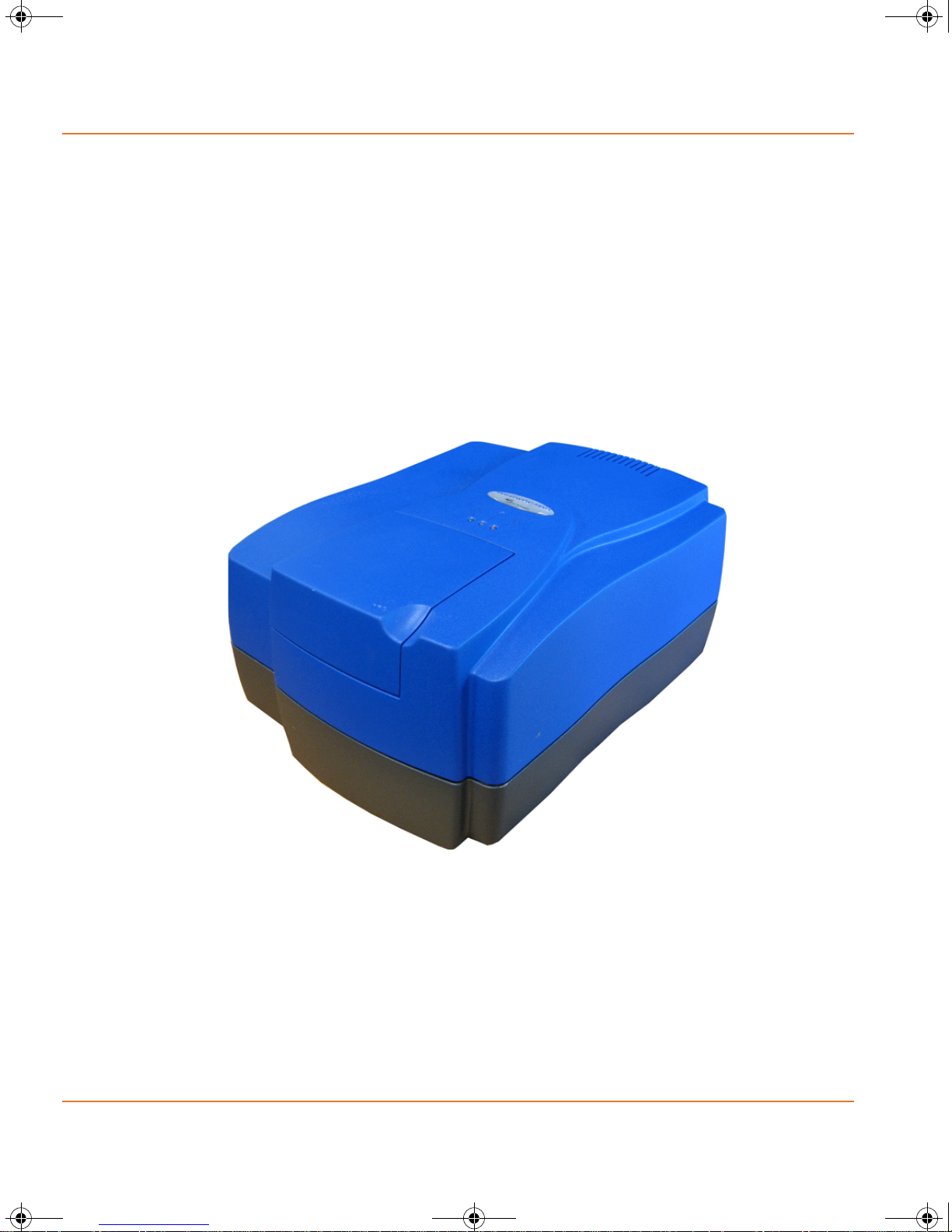
Scanner Components
The main components of the GenePix 4000B Microarray Scanner are:
• Protective enclosure
• Optics
• Lasers
• Optical path
• Emission filters
• PMTs (photo-multiplier tubes)
• Status lights
• External power supply
.
Figure 1-1 GenePix® 4000B Microarray Scanner
For detailed information about each component, see Instrument
Components on page 25.
10 5000450 D

GenePix_4000B.book Page 11 Friday, October 22, 2010 3:07 PM
Scanner Specifications
Table 1-1 Specifications
Sample type Standard microscope slides (1 inch by 3 inches, 25
Maximum scan area 22 mm by 72 mm
Maximum resolution 5 μm
Scan mode and order Simultaneous scanning of two wavelengths
Detector Dual PMTs
Signal digital output 16-bit
Image format Single or multi-image TIFF
Computer interface USB 2.0
Scan time 6.5 minutes at 10 μm resolution
Dynamic range Four orders of magnitude
Uniformity Plus or minus 10%
Dimensions 13 inches wide by 8.7 inches high by 17.4 inches long
Weight 35.8 lb (16.2 kg)
Power supply Line voltage: 85 to 264 VAC (110 to 340 VDC)
Line frequency 50 to 60 Hz
Power 85 W, Fuse: 2.0 A slow. 5 to 20 mm
GenePix 4000B Microarray Scanner User Guide
mm by 75 mm or 26 mm by 76 mm; 0.9 to 1.2 mm
thick)
(36 cm by 22 cm by 44 cm).
universal voltage input
5000450 D 11

GenePix_4000B.book Page 12 Friday, October 22, 2010 3:07 PM
Principles of Operation
Site Requirements
Table 1-2 Site Requirements
Temperature 50 to 86ºF (15 to 30ºC)
Humidity 5 to 95% non-condensing
Power Universal input 50 to 60 Hz, 100 to 240 VAC, 2A max
Space 25.6 inches deep by 16.9 inches wide by 13.4 inches high
Bench support Sufficient to support 40 lbs (18 kg) with minimal vibration
Uninterruptible
power supply
(UPS)
(65 cm by 43 cm by 34 cm). An additional 6 inches (15.2
cm) for clearance.
We recommend the use of a 325 VA UPS
12 5000450 D

GenePix_4000B.book Page 13 Friday, October 22, 2010 3:07 PM
Installation and Operation
The GenePix® 4000B Microarray Scanner should be unpacked and in
position on a flat level surface before performing any of the installation
procedures. Perform the procedures in the following order.
• Unpack the scanner and position it on the bench
• Install the software
• Turn on the scanner
• Insert a slide
Unpacking the scanner and positioning it on the bench
The GenePix 4000B Microarray Scanner is packed in a specially
designed crate. Retain the crate and the packing materials. If the
scanner requires repair, you must return it in the original packaging. If
the crate has been damaged in transit, you must retain it for inspection
by the carrier.
WARNING! Shock Hazard. In an emergency, users must be
able to safely disconnect the main power cable without moving
the scanner. Locate the scanner so that either the power outlet
or the scanner’s appliance connector is accessible.
2
WARNING! The scanner weighs 35.8 pounds (16.2 kg). To
avoid potential injury, a minimum of two people are needed to
lift the scanner.
WARNING! Biohazardous Material. Do not operate the scanner
in an environment where potentially damaging liquids or gases
are present, or in a room with a temperature below 15°C.
5000450 D 13

GenePix_4000B.book Page 14 Friday, October 22, 2010 3:07 PM
Installation and Operation
To unpack the scanner and position it on the bench
1. Open the crate and remove any foam blocks used to protect the
scanner from excessive shock and vibration during shipping.
CAUTION! Do not touch or loosen any screws or parts other than those
specifically described in the instructions. Doing so can cause
misalignment and voids the scanner warranty.
Note: Do not tilt or slide the scanner when transferring it from
the crate to its final position on a bench or desk.
2. Lift and then place the scanner on a flat level surface, away from
direct sunlight, dust, drafts, vibration, and moisture. Carefully
move the scanner to its final position.
Tip! For proper ventilation and cooling, leave at least six inches
of space between the back of the scanner and the nearest
object or surface.
3. Plug the USB cable into the USB type B port on the back of the
scanner, and the USB type A port on the control computer.
.
1
2
Figure 2-1 Connections on back of the scanner
Item Name
1 Round port for main power supply cable
2 USB type B port
14 5000450 D

GenePix_4000B.book Page 15 Friday, October 22, 2010 3:07 PM
4. Plug the round connector of the cable leading from the external
power supply into the matching power port on the back of the
scanner. Plug the main power supply cable into the external
power supply, and the lab’s power outlet.
We recommend you use a surge protector between the main
power cable and the power outlet.
.
GenePix 4000B Microarray Scanner User Guide
2
3a
1
3b
Figure 2-2 Main power supply cable components
Item Name Description
1 Round connector Plug into the matching power port on
instrument’s back panel
2 External power supply
3 Main power cable Plug end 3a into the external power
supply. Plug end 3b into the lab’s
power outlet.
5000450 D 15

GenePix_4000B.book Page 16 Friday, October 22, 2010 3:07 PM
Installation and Operation
Installing the Software
Before operating the scanner, you must install the GenePix Pro
Software on a Windows-based control computer.
To install the software
1. Locate the GenePix Pro Software CD.
Note: You must be fully aware of the information contained in
the GenePix
®
Pro Software Reference Guide to ensure a
successful software installation. The installation instructions are
provided in hard copy, and soft copy on the GenePix Pro
Software CD.
2. Read the supplied software installation instructions.
3. Insert the GenePix Pro Software CD into the computer. Follow
the InstallShield Wizard instructions to install the GenePix Pro
Software.
CAUTION! Do not to insert the security key into the control computer
until after the GenePix Pro Software has been installed.
4. Install the security key. For more information, see the GenePix®
Pro Software Reference Guide included with the GenePix Pro
Software.
16 5000450 D

GenePix_4000B.book Page 17 Friday, October 22, 2010 3:07 PM
Turning on the Scanner
Proper startup of the GenePix 4000B Microarray Scanner includes a
functional checkout procedure to confirm that the scanner is performing
according to the specifications established during commissioning before
the scanner left the factory.
To turn on the scanner
1. Make sure the slide door is closed.
2. Turn on the scanner power switch.
Tip! The GenePix 4000B Microarray Scanner power switch is
located on the instrument’s external power supply module.
GenePix 4000B Microarray Scanner User Guide
3. Turn on the control computer.
4. Click Start > Programs > Molecular Devices > GenePix
5. Click Functional Checkout in the Hardware Diagnostics
Inserting a Slide
The slide holder is a precision component designed to ensure proper
focusing and field uniformity. Improper handling can damage the slide
holder and affect imaging performance.
CAUTION! Never touch the slide holder while it is moving. Never force
the slide holder closed, or apply significant pressure to it.
Pro, and then click the Report tab.
Reports area, and follow the steps in the Wizard.
The GenePix Pro Software automatically logs hardware
performance events into the Hardware Diagnostics Report every
two hours during operation.
Note: For optimum performance, allow the GenePix 4000B
Microarray Scanner to warm up for 15 minutes before scanning
slides with the GenePix Pro Software.
To insert a slide
1. Move the slide door to the left.
The slide holder moves forward into the load position.
2. Raise the top of the slider holder.
5000450 D 17

GenePix_4000B.book Page 18 Friday, October 22, 2010 3:07 PM
Installation and Operation
3. With the slide held between your thumb and finger, carefully
place the slide, feature-side down into the slide holder.
.
Note: Make sure the barcode on the slide is facing the
front of the scanner.
.
1
Figure 2-3 Slider holder
Ite
m
Name Description
1 Slide door In open position
2 Slide holder In load position
2
3
4
3 Slide Place feature-side down
4 Barcode Barcode is facing the front of the scanner
4. Lower the top of the slide holder.
18 5000450 D

GenePix_4000B.book Page 19 Friday, October 22, 2010 3:07 PM
CAUTION! Make sure the top of the slide holder is lowered before
closing the slide door.
5. Move the slide door to the right.
The slide holder moves into the scan position.
Shutting Down the Scanner
Proper shutdown of the GenePix 4000B Microarray Scanner ensures the
scanner or software are not damaged.
To shut down the scanner
1. Close the GenePix Pro Software.
2. Turn off the scanner power switch.
GenePix 4000B Microarray Scanner User Guide
Tip! The GenePix 4000B Microarray Scanner power switch is
located on the instrument’s external power supply module.
3. Turn off the control computer.
5000450 D 19

GenePix_4000B.book Page 20 Friday, October 22, 2010 3:07 PM
Installation and Operation
20 5000450 D

GenePix_4000B.book Page 21 Friday, October 22, 2010 3:07 PM
Maintenance & Troubleshooting
The GenePix® 4000B Microarray Scanner requires very little
maintenance.
WARNING! Biohazardous Material. It is your responsibility to
decontaminate the scanner, as well as any accessories, before
requesting service, or before returning the scanner or any
components.
WARNING! Biohazardous Material. Never perform any
maintenance procedures on the scanner in an environment
where potentially damaging gases or liquids are present.
WARNING! Shock Hazard. Do not remove the protective
enclosure or any covers marked with the high-voltage warning
symbol.
3
WARNING! Shock Hazard. Always turn the power switch off
and disconnect the main power cable before performing any
maintenance procedures.
WARNING! The scanner weighs 35.8 pounds (16.2 kg). To
avoid potential injury, a minimum of two people are needed to
lift the scanner.
CAUTION! Do not touch or loosen any screws or parts other than those
specifically described in the maintenance procedures. Doing so can
cause misalignment, and voids the scanner warranty.
5000450 D 21

GenePix_4000B.book Page 22 Friday, October 22, 2010 3:07 PM
Maintenance & Troubleshooting
Moving the Scanner
If the GenePix 4000B Microarray Scanner must be moved within the
lab, or returned to the factory for service, the scanner must be
prepared for transport.
If you do not have the original shipping crate, contact us and a new
crate can be provided for an additional charge.
To move the scanner
CAUTION! Always use the Park Scanner utility prior to moving the
scanner. Failure to park the scanner can result in misalignment or
damage of the optical system.
1. Remove any slide from the slide holder.
2. Close the GenePix Pro Software.
3. Click Start > Programs > Molecular Devices > GenePix Pro
> GenePix Utilities.
The GenePix Utilities window appears
4. Click Park Scanner for Shipping.
A message box appears informing you that the scanner has
been successfully parked.
CAUTION! Always turn off power to the scanner using the power switch.
Do not turn off the power by unplugging the main power cable from the
power outlet.
5. Turn off the scanner power switch.
Tip! The GenePix 4000B Microarray Scanner power switch is
located on the instrument’s external power supply module.
Tip! Do not turn on the power switch after parking the scanner.
6. Unplug the main power cable (including the external power
supply) from the back of the scanner and the lab’s power outlet.
CAUTION! Never unplug the USB cable unless the scanner has been
turned off and the main power cable has been disconnected.
22 5000450 D

GenePix_4000B.book Page 23 Friday, October 22, 2010 3:07 PM
7. Unplug the USB cable from the back of the scanner and the
control computer.
CAUTION! Do not tilt or stand the scanner on its end when moving it
within the lab, or transferring it from the bench to the shipping crate.
8. If the scanner is to returned for service, pack the scanner in its
original shipping crate. Otherwise, have two people lift the
scanner or place it on a rolling cart to transport it to the new
location.
9. For information on installing the scanner in a new location, see
Unpacking the scanner and positioning it on the bench on
page 13.
Note: When the scanner is turned on, the scanner is
automatically removed from park state.
GenePix 4000B Microarray Scanner User Guide
Interlock Failure Symptoms
WARNING! Laser Hazard. Never operate the scanner if you
suspect an interlock has failed. Doing so exposes the user to
laser radiation.
If an interlock fails, do not operate the 4000B Microarray Scanner. Shut
down the scanner and contact Technical Support immediately.
The following are typical symptoms of an interlock failure.
• The mirror and lens assembly keep moving below the slide after
the door is opened.
• The blue Scanning LED on the front of the scanner does not
extinguish when the slide door is open.
• The GenePix Pro Software does not recognize the scanner or the
slide.
• You can no longer hear the distinctive metal-on-metal sound
that the mechanical interlock makes when it falls into place. This
occurs when the slide loading door has opened about one
quarter inch.
5000450 D 23

GenePix_4000B.book Page 24 Friday, October 22, 2010 3:07 PM
Maintenance & Troubleshooting
Fuses
If the GenePix 4000B Microarray Scanner does not start up, a fuse
might no longer be functioning. If you suspect a fuse has stopped
functioning, contact Technical Support.
24 5000450 D

GenePix_4000B.book Page 25 Friday, October 22, 2010 3:07 PM
Instrument Components
The main components of the GenePix® 4000B Microarray Scanner are
described below.
Protective enclosure
The protective enclosure protects the user from exposure to laser
radiation, high voltage, and moving parts.
WARNING! Laser Hazard! Do not remove the protective
enclosure. Operating the scanner with the protective enclosure
removed exposes the user to laser radiation.
Optics
The GenePix 4000B Microarray Scanner uses a laser-excitation based
fluorescence scanning and imaging system. The optical system consists
of excitation light, mirrors, lenses, filters, and photo-detection.
A
Lasers
In the GenePix 4000B Microarray Scanner, laser excitation is provided
by individual 532 nm and 635 nm lasers. These wavelengths
correspond to the ideal wavelengths used to excite the fluorophores
Cy3 and Cy5 (GE Healthcare), or other fluorophores with similar
fluorescent characteristics. The individual lasers have been selected
because of their superior optical performance and reliability. Since the
performance of such lasers is often sensitive to external temperature
fluctuations, the scanner uses an active temperature stabilization
design to minimize temperature-based laser fluctuations. The GenePix
4000B Microarray Scanner automatically corrects fluorescent intensity
for normal variations on a pixel-by-pixel basis.
With the GenePix 4000B Microarray Scanner, laser power can be set to
100%, 33%, or 10% of the total laser output. This feature can be used
when the fluorescence of the sample is too bright, or when
photobleaching is a problem.
5000450 D 25

GenePix_4000B.book Page 26 Friday, October 22, 2010 3:07 PM
Instrument Components
Optical Path
Excitation laser light is directed onto the slide after passing through a
series of filters and mirrors. While laser light is by definition very
narrow band, the GenePix 4000B Microarray Scanner employs
additional optical filters to make sure that no spurious excitation light is
directed onto the slide. If the laser light impinges on an appropriate
fluorophore bound on the slide, emission light of a longer wavelength is
emitted. These emission photons are directed back through the optical
system where they pass through another bandpass filter before
reaching the photodetector.
One problem faced by dual scanning systems is crosstalk, where the
two different wavelengths of light are not sufficiently separated in the
scanning system. For example, emission light from one fluorophore can
be recorded by the detector for the second fluorophore, or spurious
excitation light for the first fluorophore can bleed back in into the
detector for the second fluorophore. Crosstalk is often a concern when
using a pair of fluorophores that have similar spectral properties. The
result can be an erroneous contribution of fluorescence from one optical
channel to the other.
The GenePix 4000B Microarray Scanner employs two approaches to
reduce crosstalk to negligible levels. First, the filter sets and excitation
lasers have been carefully chosen to ensure that crosstalk between the
two fluorophores is minimized. Second, and more importantly, the
patented optical design guarantees that the light paths of the two
channels are spatially separated.
The GenePix 4000B Microarray Scanner includes a user-controlled
focusing feature. The focal plane at the zero position is at the surface of
the glass slide, with a total depth of focus of 64 μm, equally distributed
on both sides of the focal plane (depth of focus is defined as the range
over which the signal is within 50% of the maximum signal). The
GenePix Pro Software allows you to set the focal plane from –50 μm to
+200 μm relative to the zero position. Positive positions refer to focal
planes above the microarray surface while negative positions are within
the slide.
Emission Filters
The GenePix 4000B Microarray Scanner is equipped with two lasers.
Each laser (red and green) includes a matching pre-installed emission
filter.
• Standard red (660 nm to 690 nm; 670DF40)
• Standard green (558 nm to 593 nm; 575DF35575)
Each emission filter is optimized for the emission spectrum of the
respective dye, designed to reject laser light at OD 8 (optical density)
for each respective laser excitation, and reject broad-spectrum light at
OD 5.
26 5000450 D

GenePix_4000B.book Page 27 Friday, October 22, 2010 3:07 PM
PMT
The GenePix 4000B Microarray Scanner uses two high-sensitivity, lownoise PMTs to detect the emitted fluorescent light. A PMT converts
incident photons into electrons through the photoelectric effect. When
an incident photon impinges on the active surface of the PMT (the
photocathode), an electron is generated. The electron flows through a
series of electron multipliers (dynodes) to the anode. The amount of
current that flows from the anode is directly proportional to the number
of photons at the photocathode.
The amount of amplification a PMT can produce depends on the number
of dynodes in the PMT, and the voltage that is applied to the PMT. It is
possible to achieve a signal amplification of 107. Increasing the PMT
voltage setting in the GenePix Pro Software, increases the signal
amplification of the PMT.
GenePix 4000B Microarray Scanner User Guide
Note: When the PMT gain is increased, the sensitivity to non-specific
fluorescence is also increased, as is the electronic noise in the system.
The increase in noise can often be overcome by line averaging;
however, the result is decreased acquisition speed and increased
photobleaching. In general, the signal-to-noise ratio is not improved
by increasing the PMT voltage.
The output of a PMT is typically linear over a wide range of incident light
intensities. However, there is a very non-linear relationship between
the voltage of the PMT and the PMT output. Therefore, a slide scanned
at a PMT voltage of 800 V will not be twice as bright as the same slide
scanned at 400 V.
Signal amplification by the PMT is controlled by adjusting the PMT gain
in the GenePix Pro Software. The PMT gain is related to the PMT voltage
by a calibration constant such that:
PMT gain = PMT voltage / calibration constant
The calibration constant is derived by performing the system calibration
in Hardware Diagnostics and will ensure that the scanner performance
is self-consistent over time. For an uncalibrated scanner the constant is
1.000.
5000450 D 27

GenePix_4000B.book Page 28 Friday, October 22, 2010 3:07 PM
Instrument Components
Status Lights
Three lights on the front of the GenePix 4000B Microarray Scanner
indicate status.
• Device standby
• Scanning
• Eject
.
1
3
2
Figure A-1 Status lights – GenePix® 4000B Microarray Scanner
Item Color Name Description
1 Green Device standby The scanner is powered up and ready
to scan a slide
2 Blue Scanning The slide is in the load position and is
being scanned
3 Orange Eject The slideholder is ready to be
unloaded
28 5000450 D

GenePix_4000B.book Page 29 Friday, October 22, 2010 3:07 PM
Instrument Performance Factors
Spatial resolution, and dynamic range and detection limits are two key
principles of the GenePix
Spatial Resolution
In the GenePix 4000B Microarray Scanner, a single beam of light is
rapidly scanned across the microarray, and a composite pixelated
image is created from the digitized signals from the PMT. The spatial
resolution of the system refers to the size of the pixel. It determines
the minimum distance that can be distinguished between two points of
light. In the GenePix 4000B Microarray Scanner, the smallest spatial
resolution is 5 μm.
It is possible to change the resolution of data scans by changing the
pixel size setting in the GenePix Pro Software. It is important to note
that this does not change the size of the scanning beam. The GenePix
4000B Microarray Scanner implements changes in resolution by
increasing the Y-direction step size and averaging the X-direction
samples over multiples of 5 μm spots. For example, to change the pixel
size from 5 μm to 10 μm, the instrument only scans every second
X-direction line (by increasing each Y-direction step from 5 μm to 10
μm). Consequently a 10 μm scan is twice as fast as a scan at 5 μm, and
outputs the average of each adjacent pair of 5 μm spots in the
X-direction as the value of a single 10 μm pixel. Similarly, a scan at 20
μm pixel size is implemented by scanning every fourth X-direction line
(and so is four times faster than at 5 μm) and using the average of four
contiguous 5 μm spots on each X-direction line as the value of a 20 μm
pixel.
Data scan pixel size can be increased beyond 20 μm in increments of
20 μm, but the scanning pattern (and therefore scan duration) remains
the same. Every fourth X-direction line is scanned, and the spots within
the larger pixel size are averaged. For example, a 60 μm data scan will
average the values of thirty-six 5 μm spots (three X-direction lines
contribute twelve 5 μm spots each) to calculate the value for each 60
μm pixel. See Figure B-1 Data scans on page 30.
Changing the resolution of a data scan can often be useful if you have
large features and you do not need to scan at maximum resolution. As
the resolution is decreased, so is the final image size (in megabytes).
However, keep in mind that you need to acquire enough pixels for each
feature in order to make accurate measurements.
®
4000B Microarray Scanner operation.
B
5000450 D 29

GenePix_4000B.book Page 30 Friday, October 22, 2010 3:07 PM
Instrument Performance Factors
For a preview scan, the same 5 μm spots are scanned. However the
Y-direction step size is increased to 40 μm, and each 40 μm preview
scan pixel is an average of eight contiguous 5 μm spots in the
X-direction. This speeds image acquisition for balancing the PMT gains
while minimizing photobleaching.
Figure B-1 Data scans.is a representation of how the GenePix 4000B
Microarray Scanner samples 5 μm spots and averages them to calculate
the values of the image pixels for the various scan modes and pixel
sizes. On the left side of each image pair is the raw data scan from the
scanner. Each square represents a 5 μm by 5 μm spot as scanned by
the 5 μm laser beam. On the right are the resultant image pixels at
various resolutions. The shading indicates the spots that are scanned
as well as the corresponding pixels in the final image.
.
Figure B-1 Data scans
30 5000450 D

GenePix_4000B.book Page 31 Friday, October 22, 2010 3:07 PM
Dynamic Range and Detection Limit
The dynamic range of an instrument is the range of signal values over
which the instrument can accurately measure change. The GenePix
4000B Microarray Scanner has a dynamic range of 10
is determined primarily by the design of the PMT. In the 4000B
Microarray Scanner, the voltage (gain) applied to the PMT can be
adjusted to change the amplification of the signal as electrons pass
through the PMT. The optimum working range is 400 V to 1000 V. If the
gain is set below this range, the probability that each impinging photon
will be converted to an electron is diminished, and the dynamic range
will be limited on the low end. Above this range, noise begins to
interfere with accurate signal measurement. Both of these cases will
limit the dynamic range.
The dynamic range of an instrument is often considered in conjunction
with its detection limit. The detection limit is defined as the dye
concentration for which the signal-to-noise ratio = 3. Signal-to-noise
ratio is calculated as:
GenePix 4000B Microarray Scanner User Guide
4
. Dynamic range
(Signal – Background) / Standard Deviation of Background
Although you might be able to see features below this level, the
quantitative accuracy diminishes significantly.
5000450 D 31

GenePix_4000B.book Page 32 Friday, October 22, 2010 3:07 PM
Instrument Performance Factors
32 5000450 D

GenePix_4000B.book Page 33 Friday, October 22, 2010 3:07 PM
Warranty and Service
Molecular Devices is committed to ensuring the highest quality of our
products and customer service.
If you have any problems with your GenePix® 4000B Microarray
Scanner, contact our Technical Support group. In the US, contact us at
1-800-635-5577. For locations outside the United States, please
contact your local sales representative.
Standard Warranty
Molecular Devices warrants its non-consumable hardware products to
be free from defects in materials and workmanship for 12 months from
date of invoice or date of purchased installation visit, whichever is later.
The warranty covers the cost of parts and labor to repair the product.
Please keep the shipping container for future use. If you require an
additional container, one can be provided for an additional charge.
Products returned to Molecular Devices for repair should be properly
packaged with transportation charges prepaid. Molecular Devices will
pay for the return shipping of the product to the customer. If the
shipment is to a location outside the United States, the customer is
responsible for all duties, taxes and freight clearance charges.
The warranty is valid when the product is used for its intended purpose
and does not cover products which have been modified without
approval from Molecular Devices, or which have been damaged by
abuse, accident or connection to incompatible equipment.
This warranty is in lieu of all other warranties, expressed or implied.
C
Out-of-Warranty Repair Service
Out-of-warranty repair service is available. Contact Molecular Devices
Technical Support for more information.
Optional Service Agreement
Purchasing an optional Service Agreement extends the coverage of the
Standard Warranty. Contact the supplier for current rates.
5000450 D 33

GenePix_4000B.book Page 34 Friday, October 22, 2010 3:07 PM
Warranty and Service
Technical Support
In order to receive the best possible technical support, we encourage
you to register on our website www.moleculardevices.com, especially if
your sales transaction was conducted by a purchasing agent. Your
name in our database ensures that we can contact you directly with
important information about product upgrades and special promotional
opportunities. Once you register your name, you can then register your
instrument.
If you require advice on the use of your GenePix 4000B Microarray
Scanner, do not hesitate to contact Molecular Devices Technical
Support. Visit the website http://support.moleculardevices.com and
complete the Technical Support Request form. You can also phone
Molecular Devices Technical Support.at 800-635-5577. Follow the
prompts for “GenePix Technical Support”.
At Molecular Devices, staying in touch with all our customers is a
valuable part of our ongoing development process, ensuring the
excellence of every product we offer.
34 5000450 D
 Loading...