

Page 1
FlexStation® 3 Benchtop Multi-Mode
Microplate Reader
User Guide
0112-0127 B
June 2013
www.moleculardevices.com
Page 2

This document is provided to customers who have purchased Molecular Devices
equipment, software, reagents, and consumables to use in the operation of such
Molecular Devices equipment, software, reagents, and consumables. This document
is copyright protected and any reproduction of this document, in whole or any part,
is strictly prohibited, except as Molecular Devices may authorize in writing.
Software that may be described in this document is furnished under a nontransferrable license. It is against the law to copy, modify, or distribute the software
on any medium, except as specifically allowed in the license agreement.
Furthermore, the license agreement may prohibit the software from being
disassembled, reverse engineered, or decompiled for any purpose.
Portions of this document may make reference to other manufacturers and/or their
products, which may contain parts whose names are registered as trademarks and/or
function as trademarks of their respective owners. Any such usage is intended only to
designate those manufacturers’ products as supplied by Molecular Devices for
incorporation into its equipment and does not imply any right and/or license to use
or permit others to use such manufacturers’ and/or their product names as
trademarks.
Each product is shipped with documentation stating specifications and other
technical information. Molecular Devices products are warranted to meet the stated
specifications. Molecular Devices makes no other warranties or representations
express or implied, including but not limited to, the fitness of this product for any
particular purpose and assumes no responsibility or contingent liability, including
indirect or consequential damages, for any use to which the purchaser may put the
equipment described herein, or for any adverse circumstances arising therefrom. The
sole obligation of Molecular Devices and the customer's sole remedy are limited to
repair or replacement of the product in the event that the product fails to perform as
warranted.
For research use only. Not for use in diagnostic procedures.
The trademarks mentioned herein are the property of Molecular Devices, LLC or their respective owners. These
trademarks may not be used in any type of promotion or advertising without the prior written permission of
Molecular Devices, LLC.
Patents:
Product manufactured by Molecular Devices, LLC.
1311 Orleans Drive, Sunnyvale, California, United States of America 94089.
Molecular Devices, LLC is ISO 9001 registered.
© 2013 Molecular Devices, LLC.
All rights reserved.
http://www.moleculardevices.com/productpatents
Page 3

Contents
Chapter 1: Description . . . . . . . . . . . . . . . . . . . . . . . . . . . . . . . . . . 7
Introduction. . . . . . . . . . . . . . . . . . . . . . . . . . . . . . . . . . . . . . . . . . . . . . 7
How To Use This User Guide . . . . . . . . . . . . . . . . . . . . . . . . . . . . . . . . 9
User Guide Organization . . . . . . . . . . . . . . . . . . . . . . . . . . . . . . . . . . 9
Safety Information . . . . . . . . . . . . . . . . . . . . . . . . . . . . . . . . . . . . . . . . 9
Conventions Used for Precautionary Information. . . . . . . . . . . . . 10
Electrical Safety . . . . . . . . . . . . . . . . . . . . . . . . . . . . . . . . . . . . . . . . 10
Service-Trained Users . . . . . . . . . . . . . . . . . . . . . . . . . . . . . . . . . . . 11
Avoiding Mechanical Problems During Fluid Transfer . . . . . . . . . 11
Safety Messages . . . . . . . . . . . . . . . . . . . . . . . . . . . . . . . . . . . . . . . . 11
System Overview. . . . . . . . . . . . . . . . . . . . . . . . . . . . . . . . . . . . . . . . . 13
System Components . . . . . . . . . . . . . . . . . . . . . . . . . . . . . . . . . . . . . . 15
Covers and Instrument Panels. . . . . . . . . . . . . . . . . . . . . . . . . . . . . 17
Drawers . . . . . . . . . . . . . . . . . . . . . . . . . . . . . . . . . . . . . . . . . . . . . . . 21
Fluidics Module. . . . . . . . . . . . . . . . . . . . . . . . . . . . . . . . . . . . . . . . . 24
Detection Module . . . . . . . . . . . . . . . . . . . . . . . . . . . . . . . . . . . . . . 26
Computer . . . . . . . . . . . . . . . . . . . . . . . . . . . . . . . . . . . . . . . . . . . . . 28
Accessories . . . . . . . . . . . . . . . . . . . . . . . . . . . . . . . . . . . . . . . . . . . . 28
Consumables. . . . . . . . . . . . . . . . . . . . . . . . . . . . . . . . . . . . . . . . . . . 30
Overview of Operation . . . . . . . . . . . . . . . . . . . . . . . . . . . . . . . . . . . . 32
Choosing an Experiment . . . . . . . . . . . . . . . . . . . . . . . . . . . . . . . . . 32
Preparing the Instrument . . . . . . . . . . . . . . . . . . . . . . . . . . . . . . . . 32
Preparing the Software . . . . . . . . . . . . . . . . . . . . . . . . . . . . . . . . . . 33
Running the Experiment . . . . . . . . . . . . . . . . . . . . . . . . . . . . . . . . . 33
Analyzing the Data . . . . . . . . . . . . . . . . . . . . . . . . . . . . . . . . . . . . . . 33
Theory of Operation . . . . . . . . . . . . . . . . . . . . . . . . . . . . . . . . . . . . . . 33
Instrument Design . . . . . . . . . . . . . . . . . . . . . . . . . . . . . . . . . . . . . . 33
Assay Read Types . . . . . . . . . . . . . . . . . . . . . . . . . . . . . . . . . . . . . . . 38
SoftMax Pro Software. . . . . . . . . . . . . . . . . . . . . . . . . . . . . . . . . . . . . 41
Set Up the Reader and Software Parameters . . . . . . . . . . . . . . . . 42
Acquire Data from the Reader . . . . . . . . . . . . . . . . . . . . . . . . . . . . 43
Perform Complex Data Analysis . . . . . . . . . . . . . . . . . . . . . . . . . . . 44
User Interface . . . . . . . . . . . . . . . . . . . . . . . . . . . . . . . . . . . . . . . . . . 45
0112-0127 B 3
Page 4

FlexStation 3 Benchtop Multi-Mode Microplate Reader User Guide
Chapter 2: Installation . . . . . . . . . . . . . . . . . . . . . . . . . . . . . . . . . 49
General Precautionary Information . . . . . . . . . . . . . . . . . . . . . . . . . . 49
Unpacking the System . . . . . . . . . . . . . . . . . . . . . . . . . . . . . . . . . . . . . 50
Unpacking the Fluidics Module and Accessories . . . . . . . . . . . . . . 51
Unpacking the Detection Module . . . . . . . . . . . . . . . . . . . . . . . . . . 51
Removing the Shipping Screws . . . . . . . . . . . . . . . . . . . . . . . . . . . . 52
Installing the Fluidics Module . . . . . . . . . . . . . . . . . . . . . . . . . . . . . . . 53
Installing the Pipettor Head . . . . . . . . . . . . . . . . . . . . . . . . . . . . . . . . 56
Setting Up the Computer . . . . . . . . . . . . . . . . . . . . . . . . . . . . . . . . . . 61
Connecting the Cables . . . . . . . . . . . . . . . . . . . . . . . . . . . . . . . . . . . . . 61
Installing the Drawer Adapters . . . . . . . . . . . . . . . . . . . . . . . . . . . . . . 62
Microplate Adapter Installation. . . . . . . . . . . . . . . . . . . . . . . . . . . . 62
Compound Baseplate Installation . . . . . . . . . . . . . . . . . . . . . . . . . . 63
Installing SoftMax Pro . . . . . . . . . . . . . . . . . . . . . . . . . . . . . . . . . . . . . 63
Chapter 3: Operating Procedures . . . . . . . . . . . . . . . . . . . . . . . . 65
Overview. . . . . . . . . . . . . . . . . . . . . . . . . . . . . . . . . . . . . . . . . . . . . . . . 66
Starting Up the System . . . . . . . . . . . . . . . . . . . . . . . . . . . . . . . . . . . . 67
Using the Control Panel . . . . . . . . . . . . . . . . . . . . . . . . . . . . . . . . . . 70
Setting the Temperature . . . . . . . . . . . . . . . . . . . . . . . . . . . . . . . . . . . 72
Displaying the Temperature. . . . . . . . . . . . . . . . . . . . . . . . . . . . . . . 72
Setting the Temperature with the Control Panel . . . . . . . . . . . . . .73
Setting the Temperature with SoftMax Pro Software . . . . . . . . . . 74
Setting Up the Software . . . . . . . . . . . . . . . . . . . . . . . . . . . . . . . . . . .75
SoftMax Pro Software Parameters . . . . . . . . . . . . . . . . . . . . . . . . . . . 78
Read Types. . . . . . . . . . . . . . . . . . . . . . . . . . . . . . . . . . . . . . . . . . . . . 79
Read Modes. . . . . . . . . . . . . . . . . . . . . . . . . . . . . . . . . . . . . . . . . . . . 79
Wavelengths . . . . . . . . . . . . . . . . . . . . . . . . . . . . . . . . . . . . . . . . . . . 80
Sensitivity. . . . . . . . . . . . . . . . . . . . . . . . . . . . . . . . . . . . . . . . . . . . . . 80
Timing. . . . . . . . . . . . . . . . . . . . . . . . . . . . . . . . . . . . . . . . . . . . . . . . . 81
Assay Plate Type . . . . . . . . . . . . . . . . . . . . . . . . . . . . . . . . . . . . . . . . 82
Wells to Read. . . . . . . . . . . . . . . . . . . . . . . . . . . . . . . . . . . . . . . . . . . 83
Automix . . . . . . . . . . . . . . . . . . . . . . . . . . . . . . . . . . . . . . . . . . . . . . . 84
AutoCalibrate. . . . . . . . . . . . . . . . . . . . . . . . . . . . . . . . . . . . . . . . . . . 85
Settling Time . . . . . . . . . . . . . . . . . . . . . . . . . . . . . . . . . . . . . . . . . . . 85
AutoRead . . . . . . . . . . . . . . . . . . . . . . . . . . . . . . . . . . . . . . . . . . . . . . 85
SoftMax Pro Software Parameters for Fluid Transfer. . . . . . . . . . . . 86
Compound Source. . . . . . . . . . . . . . . . . . . . . . . . . . . . . . . . . . . . . . . 87
4 0112-0127 B
Page 5

Contents
Compound Transfer . . . . . . . . . . . . . . . . . . . . . . . . . . . . . . . . . . . . . 88
Triturate Selection . . . . . . . . . . . . . . . . . . . . . . . . . . . . . . . . . . . . . . 92
Pipette Tips Layout. . . . . . . . . . . . . . . . . . . . . . . . . . . . . . . . . . . . . . 93
Compound and Tip Columns . . . . . . . . . . . . . . . . . . . . . . . . . . . . . . 93
Pipette Tip Air Gap . . . . . . . . . . . . . . . . . . . . . . . . . . . . . . . . . . . . . . 97
Settings Displayed in Plate Sections . . . . . . . . . . . . . . . . . . . . . . . . . 98
Other Software Settings . . . . . . . . . . . . . . . . . . . . . . . . . . . . . . . . . . . 99
Reading a Microplate . . . . . . . . . . . . . . . . . . . . . . . . . . . . . . . . . . . . . 99
Loading Tips and Microplates . . . . . . . . . . . . . . . . . . . . . . . . . . . . . 99
Starting the Reading. . . . . . . . . . . . . . . . . . . . . . . . . . . . . . . . . . . . 100
Selecting a Plate . . . . . . . . . . . . . . . . . . . . . . . . . . . . . . . . . . . . . . . 101
Replacing Data in a Plate . . . . . . . . . . . . . . . . . . . . . . . . . . . . . . . . 101
Viewing Experiment Progress . . . . . . . . . . . . . . . . . . . . . . . . . . . . 102
Data Display . . . . . . . . . . . . . . . . . . . . . . . . . . . . . . . . . . . . . . . . . . 102
Shutting Down the System . . . . . . . . . . . . . . . . . . . . . . . . . . . . . . . . 103
Optimizing Fluorescence Assays . . . . . . . . . . . . . . . . . . . . . . . . . . . 103
Using Spectral Scanning to Optimize Excitation and Emission
Wavelengths for Fluorescence Assays . . . . . . . . . . . . . . . . . . . . . 105
Optimizing Time-Resolved Fluorescence Assays . . . . . . . . . . . . . . 110
Optimizing Fluorescence Polarization Assays . . . . . . . . . . . . . . . . . 111
Optimizing Luminescence Assays . . . . . . . . . . . . . . . . . . . . . . . . . . 112
Chapter 4: Maintenance . . . . . . . . . . . . . . . . . . . . . . . . . . . . . . 113
Obtaining Support. . . . . . . . . . . . . . . . . . . . . . . . . . . . . . . . . . . . . . . 114
Moving the Instrument. . . . . . . . . . . . . . . . . . . . . . . . . . . . . . . . . . . 114
Cleaning the Instrument. . . . . . . . . . . . . . . . . . . . . . . . . . . . . . . . . . 115
Cleaning Up Spills . . . . . . . . . . . . . . . . . . . . . . . . . . . . . . . . . . . . . . 116
Cleaning the Fan Filter . . . . . . . . . . . . . . . . . . . . . . . . . . . . . . . . . . 116
Cleaning the Barrels on the Pipettor Head. . . . . . . . . . . . . . . . . . 117
Using the Microplate Adapters . . . . . . . . . . . . . . . . . . . . . . . . . . . . 120
Microplate Adapter Installation . . . . . . . . . . . . . . . . . . . . . . . . . . 120
Removing the Microplate Adapter . . . . . . . . . . . . . . . . . . . . . . . . 120
Using the Compound Baseplate. . . . . . . . . . . . . . . . . . . . . . . . . . . . 121
Replacing Fuses . . . . . . . . . . . . . . . . . . . . . . . . . . . . . . . . . . . . . . . . . 121
Replacing the Flash Lamp . . . . . . . . . . . . . . . . . . . . . . . . . . . . . . . . . 123
Long-Term Shutdown . . . . . . . . . . . . . . . . . . . . . . . . . . . . . . . . . . . . 128
Chapter 5: Troubleshooting Procedures. . . . . . . . . . . . . . . . . . 129
Problems During Startup . . . . . . . . . . . . . . . . . . . . . . . . . . . . . . . . . 130
0112-0127 B 5
Page 6

FlexStation 3 Benchtop Multi-Mode Microplate Reader User Guide
Opening a Drawer Manually . . . . . . . . . . . . . . . . . . . . . . . . . . . . . . .132
Understanding Potential Mechanical Problems . . . . . . . . . . . . . . . 133
Background . . . . . . . . . . . . . . . . . . . . . . . . . . . . . . . . . . . . . . . . . . . 133
Before Using the Instrument . . . . . . . . . . . . . . . . . . . . . . . . . . . . . 133
Avoiding Mechanical Problems . . . . . . . . . . . . . . . . . . . . . . . . . . . 134
In Case of Power Failure . . . . . . . . . . . . . . . . . . . . . . . . . . . . . . . . . 135
Recovering from Mechanical Problems in Flex Mode when Using
Fluidics . . . . . . . . . . . . . . . . . . . . . . . . . . . . . . . . . . . . . . . . . . . . . . . .135
Assessing a Mechanical Problem . . . . . . . . . . . . . . . . . . . . . . . . . . 136
Opening the Instrument . . . . . . . . . . . . . . . . . . . . . . . . . . . . . . . . .137
Evaluating the Tip Rack. . . . . . . . . . . . . . . . . . . . . . . . . . . . . . . . . . 138
Inspecting Inside the Fluidics Module . . . . . . . . . . . . . . . . . . . . . .139
Removing the Pipettor Head . . . . . . . . . . . . . . . . . . . . . . . . . . . . . 142
Expelling Undispensed Fluid from Tips . . . . . . . . . . . . . . . . . . . . . 145
Recovery Procedure . . . . . . . . . . . . . . . . . . . . . . . . . . . . . . . . . . . . 146
General Error Messages . . . . . . . . . . . . . . . . . . . . . . . . . . . . . . . . . .147
Error Messages . . . . . . . . . . . . . . . . . . . . . . . . . . . . . . . . . . . . . . . . 147
Other Error Messages . . . . . . . . . . . . . . . . . . . . . . . . . . . . . . . . . . .148
Tilting or Removing the Fluidics Module . . . . . . . . . . . . . . . . . . . . . 149
Tilting the Fluidics Module . . . . . . . . . . . . . . . . . . . . . . . . . . . . . . .149
Removing the Fluidics Module. . . . . . . . . . . . . . . . . . . . . . . . . . . . 151
Appendix A: Parts and Accessories . . . . . . . . . . . . . . . . . . . . . . 153
Ordering Parts and Accessories . . . . . . . . . . . . . . . . . . . . . . . . . . . .154
Appendix B: Performance Specifications . . . . . . . . . . . . . . . . . 155
Glossary . . . . . . . . . . . . . . . . . . . . . . . . . . . . . . . . . . . . . . . . . . . . 163
Index . . . . . . . . . . . . . . . . . . . . . . . . . . . . . . . . . . . . . . . . . . . . . . 167
6 0112-0127 B
Page 7

Description
Introduction
1
This chapter provides background information on the system, including
descriptions of the principal components and overviews of how the
system functions. It is divided into the following sections:
• Introduction, see page 7
• How To Use This User Guide, see page 9
• Safety Information, see page 9
• System Overview, see page 13
• System Components, see page 15
• Overview of Operation, see page 32
• Theory of Operation, see page 33
• SoftMax Pro Software, see page 41
The FlexStation® 3 Benchtop Multi-Mode Microplate Reader combines
the performance of the Molecular Devices SpectraMax® M5e MultiMode Microplate Reader with an integrated 8-channel or 16-channel
pipettor into one compact benchtop reader. This integrated system
provides users with a multi-detection platform capable of increasing the
liquid handling throughput and flexibility for biochemical-based and cellbased assays. Using an integrated 8-channel or 16-channel pipettor
increases assay flexibility by transferring reagents from 96 or 384 distinct
wells in a source plate to the read plate. This method enables users to
define individual reagents or compound concentrations to be delivered
to each well during the assay. The direct transfer from a source
microplate reduces consumption and allows more assay conditions to be
explored in a single microplate, making the system equally amenable to
agonist and antagonist assay formats. These additions can either occur
concurrently with kinetic analysis of reactions or before an assay to
automate reagent additions. Combined fluid transfer with multidetection optics provides a single reader capable of performing a broad
span of applications that pass through drug discovery and research
environments.
0112-0127 B 7
Page 8
FlexStation 3 Benchtop Multi-Mode Microplate Reader User Guide
Based on the SpectraMax M5e instrument platform, the FlexStation 3
instrument can address detection modalities including absorbance,
fluorescence intensity, fluorescence polarization, time-resolved
fluorescence, and luminescence. Dual monochromators allow users to
target the optimal assay excitation and emission wavelengths, while
eliminating the need to change expensive band pass filters between
experiments. Dual PMTs are integrated into the system to provide
flexibility to detect multiple detection modes, while a separate PMT
provides additional sensitivity for luminescence applications. Reference
diodes automatically adjust to slight fluctuations in excitation intensity to
reduce measurement noise. Absorbance applications are enhanced using
top-quality UV-grade fibers to provide high light transmission in the
lowest wavelengths. These optical characteristics enable the system
performance to be comparable to a top-of-the-line dedicated
spectrophotometer or spectrofluorometer with no trade-off between
instrument performance and the number of read modes.
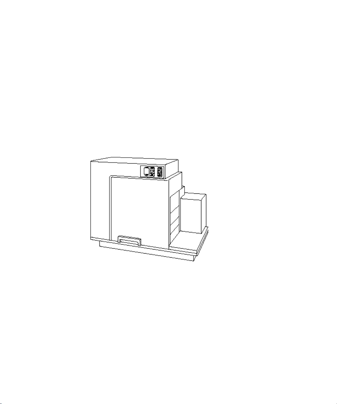
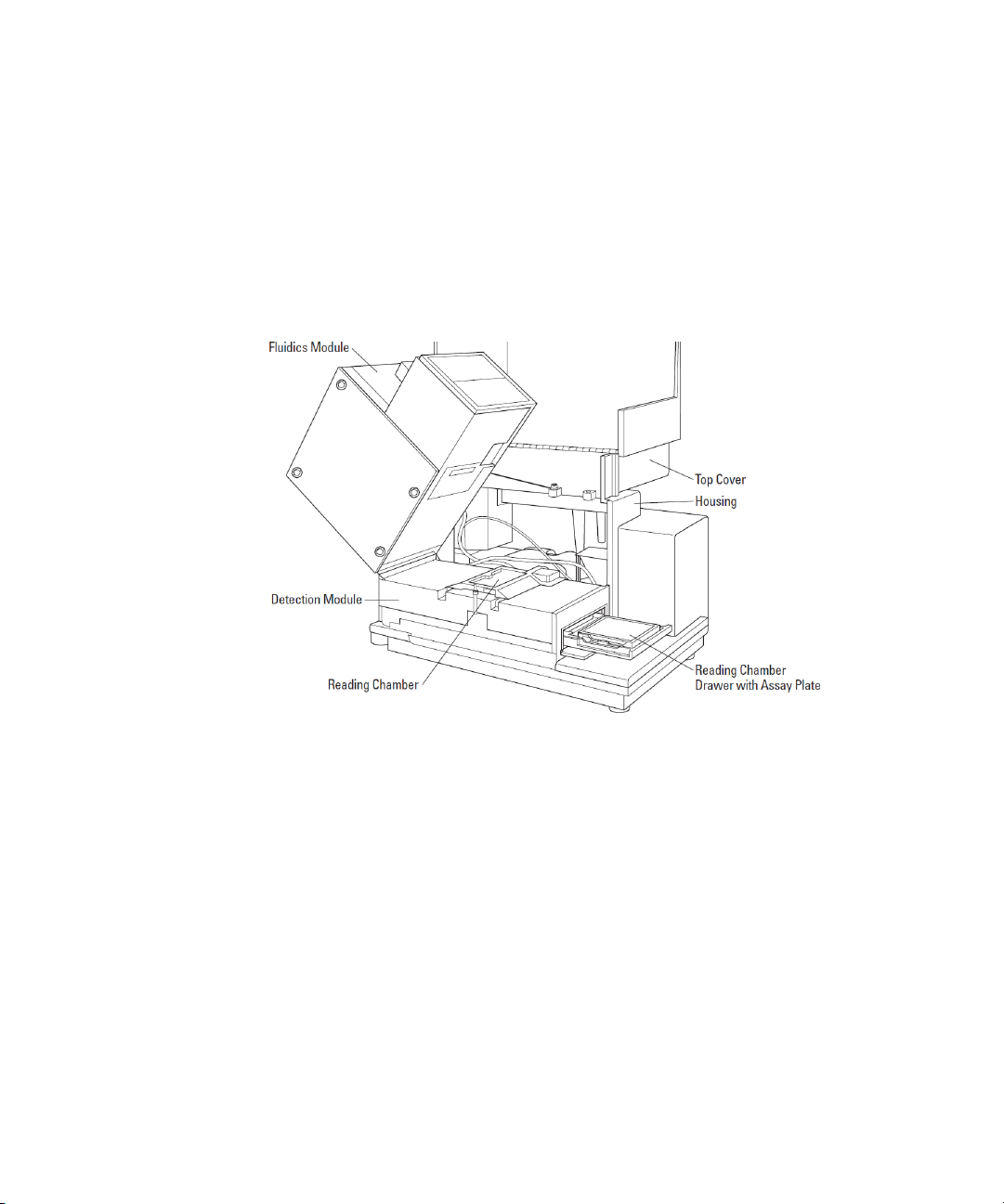
Figure 1-1: FlexStation 3 Instrument
8 0112-0127 B
Page 9

How To Use This User Guide
This user guide was written to ensure safe and proper use of the system.
Before use, read this user guide carefully to realize the full capabilities of
the system. Also, if something is unclear during daily use or if a problem
occurs, please refer to this user guide.
User Guide Organization
This user guide is organized as follows:
• Description on page 7 provides background information on the
system, including component descriptions, functional overviews,
and safety information.
• Installation on page 49 provides instructions for setting up the
reader.
• Operating Procedures on page 65 provides instructions for
starting up the reader, setting parameters for the various read
modes, and reading a microplate.
• Maintenance on page 113 provides instructions for cleaning the
fan filter, changing the fuses, and moving the system to a new
location.
• Troubleshooting Procedures on page 129 provides instructions
for diagnosing and solving common problems, as well as a list of
error conditions.
• Parts and Accessories on page 153 provides a list of spare parts.
• Performance Specifications on page 155 provides the technical
specifications for the instrument.
• Glossary on page 163 provides a list of terms and definitions.
Description
Safety Information
When operated properly in a safe environment and according to the
instructions in this user guide, there are no known hazards associated
with the FlexStation 3 instrument. However, proper use requires an
understanding of situations that are potentially dangerous and can result
in serious injury. All users must be familiar with the guidelines in this
section before working with the system.
0112-0127 B 9
Page 10
FlexStation 3 Benchtop Multi-Mode Microplate Reader User Guide
Conventions Used for Precautionary Information
This user guide uses the following conventions to provide technical and
safety information of special interest.
Note: A note gives background information that is provided to clarify a
particular step or procedure. A not can also provided an instruction to
ensure correct results and optimal performance.
CAUTION! A caution is an instruction that, if not followed, can result in
damage to the system or in loss of data.
WARNING! A warning is an instruction that, if not followed, can result
in potential injury to a person working with the system.
WARNING! BIOHAZARD. A biohazard warning indicates a condition
involving potentially infectious biological agents requiring that proper
handling precautions be taken.
Electrical Safety
WARNING! Follow all instructions in this user guide and on system
labels. If you use the system in a manner not specified by Molecular
Devices, then any protections provided by the system might be
impaired.
10 0112-0127 B
Page 11

Description
Service-Trained Users
There are two types of users described in this user guide. Most
procedures required for operating and troubleshooting can be
performed by any user who has read the instructions in this user guide
and is familiar with the system. However, all installation procedures, and
some more complex service and troubleshooting procedures, require the
expertise of a service-trained user. Whenever the following warning
message appears, a service-trained user must perform the procedure to
ensure user safety and to prevent instrument damage.
Example:
WARNING! The following procedures must be completed by a
service-trained user. Do not attempt the following procedures if you
have not been trained properly by appropriate Molecular Devices
personnel.
Avoiding Mechanical Problems During Fluid Transfer
Because of the complex mechanical nature of the FlexStation 3
instrument, including both fluidics and optical reading, smooth and
reliable operation of the system depends on both good design and
operator knowledge.
To prevent problems of a mechanical nature, be sure to read all sections
of this user guide before attempting a reading with fluidics. See
Understanding Potential Mechanical Problems on page 133.
Safety Messages
Observe the following warnings and precautions:
High internal voltages. Always turn off the power switch and unplug the
system power cord before removing labeled covers or panels.
Xenon-arc flash lamp. Do not look directly at the flash lamp while it is
illuminated. The lamp emits ultraviolet radiation at levels that can injure
the eye if viewed directly.
Electrical grounding. Never use a two-prong plug or extension cord to
connect primary power to the system. Use of a two-prong adapter
disconnects the utility ground, creating a severe shock hazard. Always
connect the system power cord directly to a three-prong receptacle with
a functional ground.
0112-0127 B 11
Page 12

FlexStation 3 Benchtop Multi-Mode Microplate Reader User Guide
Spilled liquids. Avoid spilling liquids on the system. Fluid spilled into
internal components creates a potential shock hazard. Wipe up all spills
immediately. Do not operate the system if internal components have
been exposed to spilled fluid. Unplug instrument if there is a fluid spill in
the instrument and contact Technical Support.
Replacement fuses. Use replacement fuses with the required current
rating and specification. Improper fuses or short-circuiting the fuse
holders can cause fire or damage the instrument.
Power rating. Ensure the system is connected to a power receptacle that
provides voltage and current within the specified rating for the system.
Use of an incompatible power receptacle can create electrical shock and
fire hazards.
Remove watches and jewelry before removing any panels from the
instrument.
Warning labels. There are several labels affixed to the instrument covers
and inside panels. The purpose of these labels is to alert the user to use
caution when servicing a component or the instrument. The user should
be aware that ignoring the instructions on any instrument label can
result in a hazardous condition that can cause injury.
Identification labels: The following label, among others, appears on the
instrument.
\
Figure 1-2: FlexStation 3 Instrument Label
12 0112-0127 B
Page 13

System Overview
The FlexStation 3 Benchtop Multi-Mode Microplate Reader is a
monochromator-based microplate reader that has 6-well, 12-well, 24well, 48-well, 96-well, and 384-well microplate reading capability for
absorbance, fluorescence intensity, fluorescence polarization, timeresolved fluorescence, and luminescence. When using the integrated
pipettor, the instrument offers 96-well and 384-well microplate-tomicroplate fluid transfer, 8 or 16 wells at a time.
The top portion of the instrument, the fluidics module, uses an 8-channel
or 16-channel pipettor, to expand assay flexibility by transferring
reagents from a 96-well or 384-well source plate to the assay plate.
When transferring reagents from distinct wells of a microplate, users can
define individual reagents or concentrations to be delivered in each well
during their assay. This direct transfer allows more assay conditions to be
explored in a single microplate, reducing reagent consumption as well as
making the system more amenable to both agonist and antagonist assay
formats. In addition, kinetic cell-based assay throughput (for example,
calcium mobilization) is increased when 8 or 16 wells of a microplate are
analyzed in conjunction rather than individually.
Integrated pipetting provides flexibility, and also offers users parameters
to optimize assay robustness. Trituration, mixing via aspiration and
dispense of the pipettor, encourages mixing to either resuspend source
plate compounds or spontaneously mix reagents to promote a rapid
response with minimal assay variability. Dispense parameters can also be
optimized for each experiment to accommodate cells with different
adherence characteristics to prevent cell dislodging. Furthermore, the
integrated fluidics platform uses disposable pipette tips to minimize
reagent cross contamination between wells or experiments.
The fluidics module interfaces with the lower reading chamber which
encloses a high-powered Xenon flash lamp as the light source. Sensitivity
or read-speed can be optimized by varying the number of lamp flashes
per read.
The two holographic diffraction grating monochromators allow selection
of any wavelength between 200 nm and 1000 nm in absorbance; 250 nm
and 850 nm in fluorescence intensity, time-resolved fluorescence (TRF),
or luminescence; and 400 nm and 750 nm for readings in fluorescence
polarization. Excitation and emission wavelengths are optimized using
the mirrored optics to focus light into the sample volume, and cutoff
filters to reduce stray light and minimize background interference.
Description
0112-0127 B 13
Page 14

FlexStation 3 Benchtop Multi-Mode Microplate Reader User Guide
The system has five assay types available which include Flex, Endpoint,
Kinetic, Spectrum, and multi-point Well Scan. Flex mode assay enables
users to transfer fluid from the source read plate while immediately
reading a fast kinetic assay that uses absorbance, fluorescence, or
luminescence detection technologies. Alternatively, the pipettor head
can be used to transfer fluid before an endpoint or kinetic assay to
automate fluid transfer and minimize user interaction.
In addition to fluid transfer, well contents can be mixed automatically by
shaking before each read cycle, making it possible to perform kinetic
analysis of solid-phase, enzyme-mediated reactions.
Top detection in microplates is available for all fluorescence and
luminescence readings. Bottom detection is available for all assay types
except fluorescence polarization. When reading absorbance at
wavelengths below 340 nm, special UV-transparent, disposable or quartz
microplates that allow transmission of the far ultraviolet spectra must be
used.
A plate drawer adapter is provided with the reader. The adapter is
required for optimum performance when reading from the top or
bottom of standard 96-well and 384-well microplates in all read types,
including absorbance.
Variations in measured fluorescence values are virtually eliminated by
internal compensation for detector sensitivity, photomultiplier tube
voltage, and excitation source intensity.
Using the FlexStation 3 instrument with the PathCheck® Pathlength
Measurement Technology allows normalization of variable well volumes
to absorbance readings. In addition PathCheck technology allows for
pipettor validation, including the online 8-channel and 16-channel
pipettors, and to compare experiments from different days.
Temperature in the microplate chamber is isothermal, both at ambient
and when the incubator is turned on. When the incubator is on, the
reading chamber temperature can be controlled from 2°C above ambient
room temperature to 45°C. Please note that the temperature of the
fluidics module is not regulated and that it is recommend that any
microplates or tips should be at the desired temperature before placing
them inside the instrument.
14 0112-0127 B
Page 15

The FlexStation 3 instrument is controlled by an external computer
running the SoftMax® Pro Microplate Data Acquisition and Analysis
Software, which provides integrated instrument control, data display,
and statistical data analysis. The on-board microprocessor calculates and
reports the absorbance, percent transmittance, fluorescence, or
luminescence for each well of a microplate. Data from multiple
wavelengths can be acquired and ratio analysis can be performed during
a single reading, if desired. In addition, different calculations can be
made based on this data using the SoftMax Pro software, including the
subtraction of blanks, quantitation from standard curves, calculation of
IC50 values, and more.
The extreme flexibility and high sensitivity of the FlexStation 3 reader
makes it appropriate for applications within the fields of biochemistry,
cell biology, immunology, toxicology, molecular biology, and
microbiology. Online fluidic integration expands the capabilities of the
instrument to include fast fluorescence (calcium mobilization),
luminescence, and absorbance assays in addition to typical applications
which include ELISA, nucleic acid and protein quantitation,
homogeneous and heterogeneous enzyme-activity assays, and microbial
growth, endotoxin testing, and reporter-gene assays.
System Components
Description
This section describes the major system components listed below.
• Covers and Instrument Panels, see page 17
• Drawers, see page 21
• Fluidics Module, see page 24
• Detection Module, see page 26
• Computer, see page 28
• Accessories, see page 28
• Consumables, see page 30
0112-0127 B 15
Page 16

FlexStation 3 Benchtop Multi-Mode Microplate Reader User Guide
Figure 1-3: Instrument, Front View
Figure 1-4: Instrument, Rear View
16 0112-0127 B
Page 17
Description
Covers and Instrument Panels
Top Cover
The instrument is protected by a molded plastic housing. The large top
cover protects the fluidics module and the exposed portions of the
detection module.
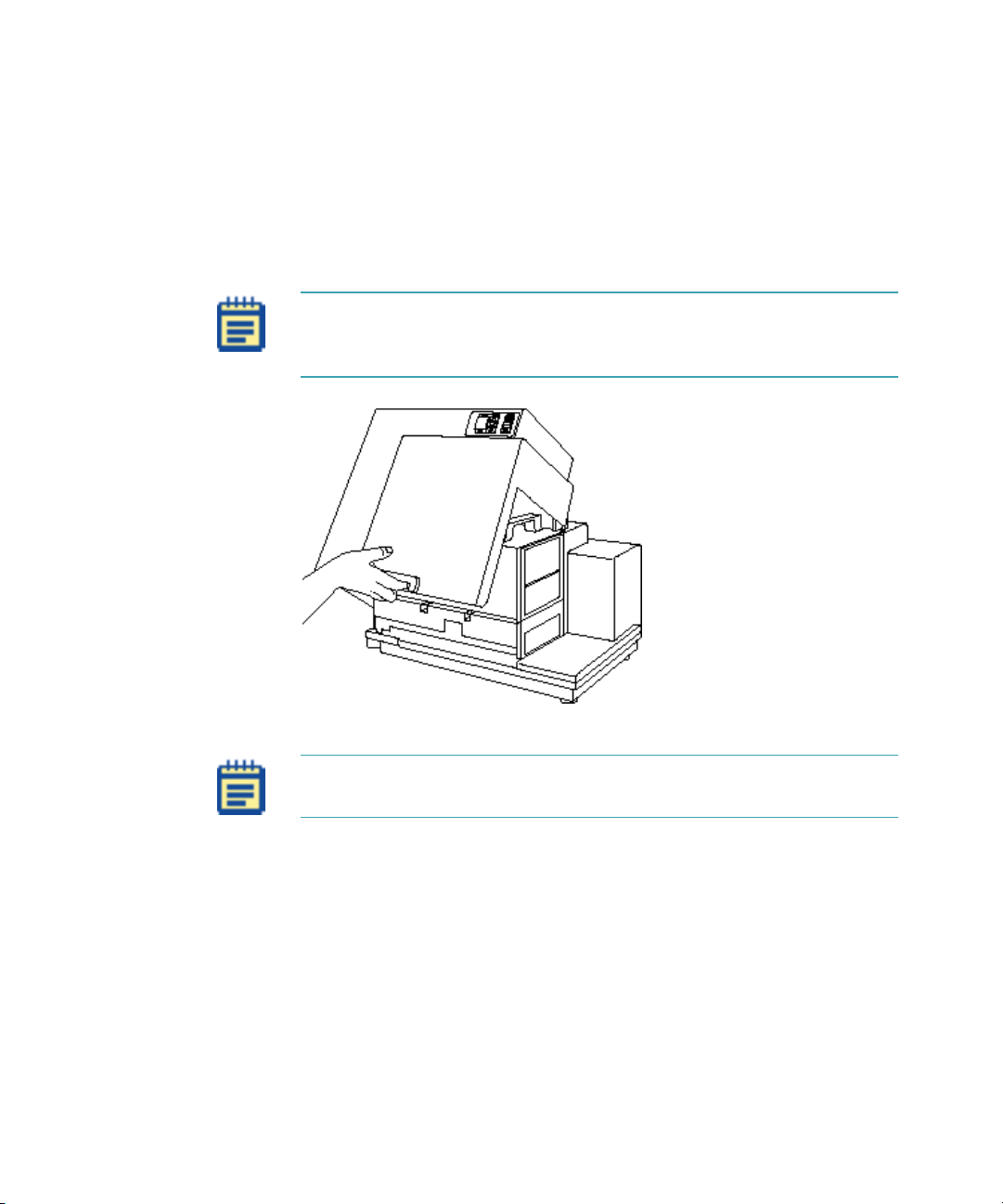
Note: The top cover can be lifted back, as shown in the figure below,
for certain limited troubleshooting procedures. See
Instrument on page 137.
Opening the
Figure 1-5: Lifting Off the Top Cover
Note: To achieve optimal performance during readings, you must
operate the system with the top cover in place.
0112-0127 B 17
Page 18
FlexStation 3 Benchtop Multi-Mode Microplate Reader User Guide
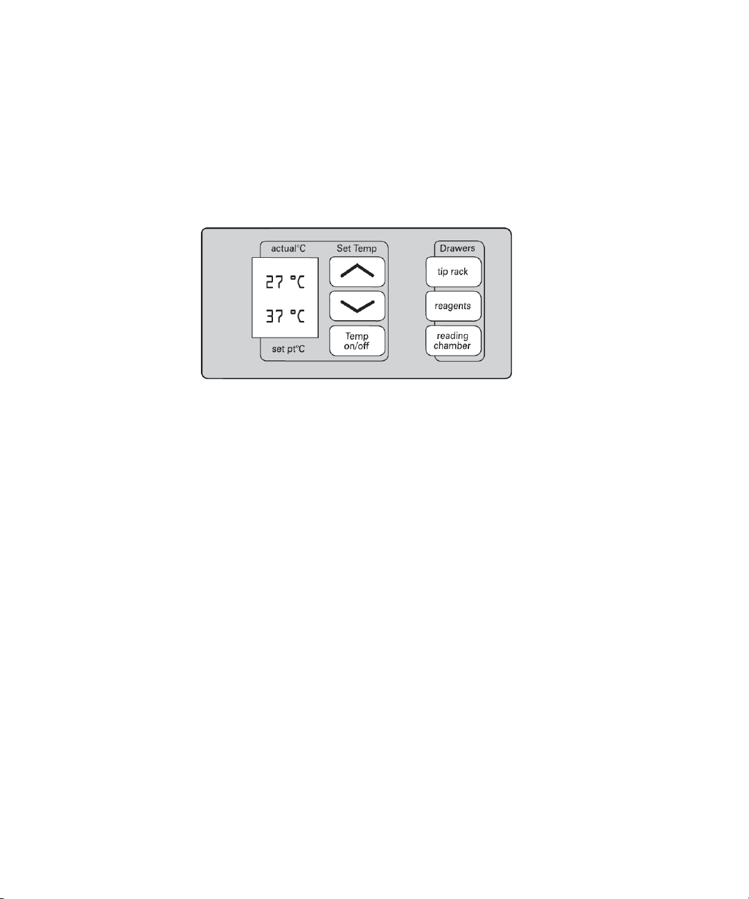
Control Panel
The control panel consists of an LCD and six pressure-sensitive
membrane keys which can be used to initiate and regulate the
temperature and to open and close the drawers.
A 2×3-character liquid crystal display (LCD) shows the current instrument
temperature at all times, and the set point temperature when the
incubator is on.
Figure 1-6: Control Panel
Starting Up the System on page 67 and Setting the Temperature on
See
page 72.
18 0112-0127 B
Page 19
Description
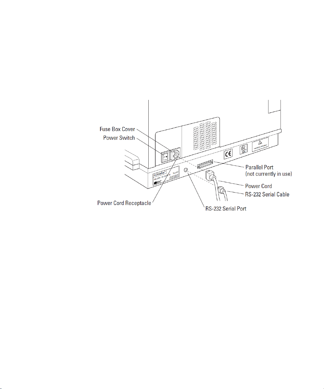
Input/Output Panels
There are two input/output panels on the rear of the instrument.
• The upper input/output panel, on the back cover, consists of a
power switch, fuse box cover, and power cord receptacle.
• The lower panel consists of an RS-232 serial port and parallel
port (not currently active). There are also a number of
identification labels.
Figure 1-7: Input/Output Panels.
For information about attaching the computer cable and power cords to
the instrument, see
0112-0127 B 19
Connecting the Cables on page 61.
Page 20
FlexStation 3 Benchtop Multi-Mode Microplate Reader User Guide
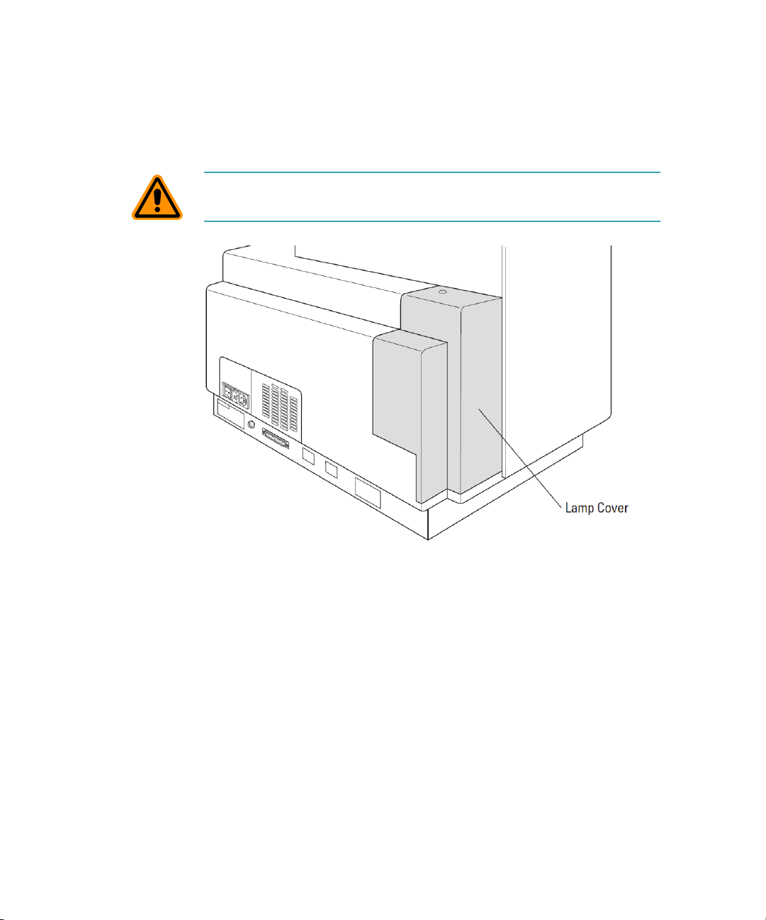
Lamp Cover
The plastic lamp cover provides access to the flash lamp on the right side
of the instrument (as viewed from the rear).
CAUTION! Flash lamp access and maintenance are restricted to servicetrained users.
Figure 1-8: Rear View
Replacing the Flash Lamp on page 123.
See
20 0112-0127 B
Page 21
Description
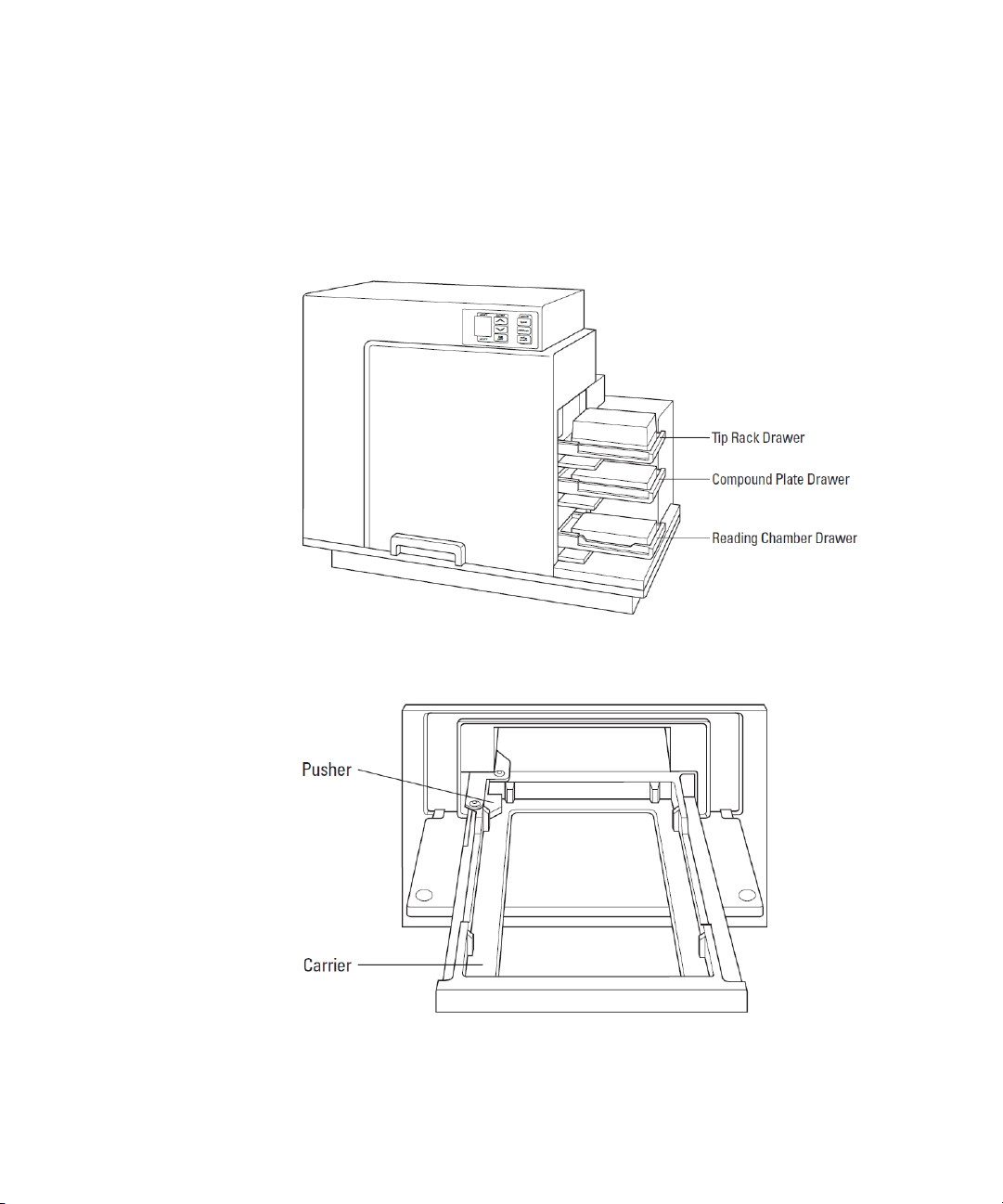
Drawers
The instrument has three drawers that open on the right side. The two
drawers in the fluidics module open and close to move the pipette tip
rack and compound plates (or reservoirs) into and out of the instrument.
The reading chamber drawer in the detection module transports the
assay microplate into the reading chamber.
Figure 1-9: Instrument with Drawers Open and Carriages Accessible
Small plastic pushers, in the front left corner of each drawer, hold the
plates, racks, or reservoirs securely in place when the drawers are closed.
Figure 1-10: Drawer Detail
0112-0127 B 21
Page 22
FlexStation 3 Benchtop Multi-Mode Microplate Reader User Guide
CAUTION! Do not obstruct the movement of any of the drawers. If you
must retrieve a plate after an error condition or power outage, and if the
drawer will not open, it is possible to open the drawer manually. See
Opening a Drawer Manually on page 132.
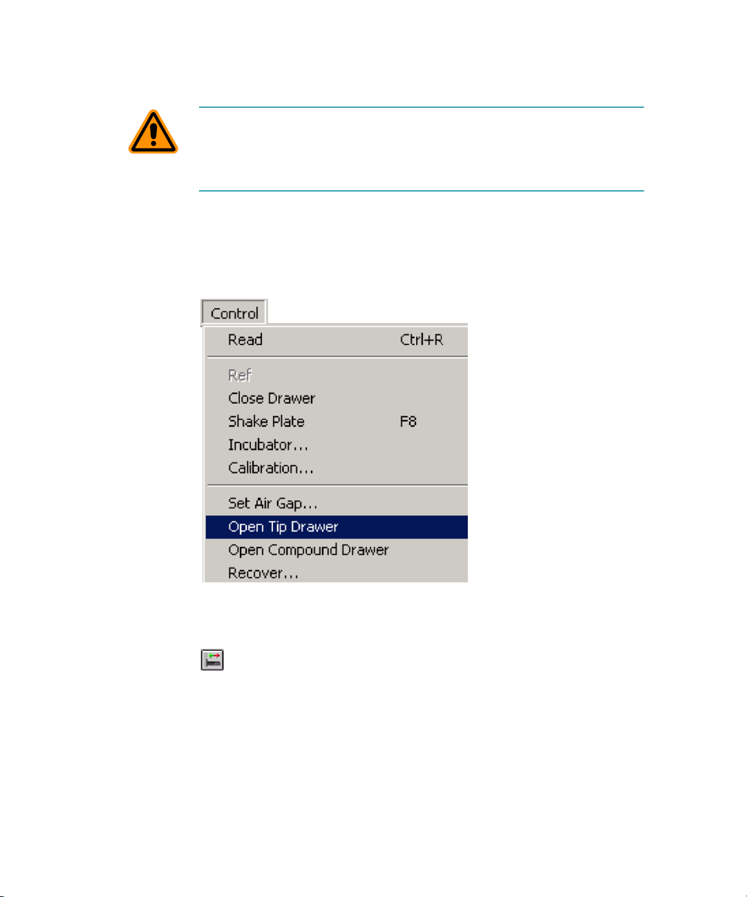
You can open and close the drawers using either the SoftMax Pro
Software or by pressing the drawer keys on the instrument control panel.
Using the SoftMax Pro Software, open the Control menu and click Tip
Drawer for the tip rack drawer, Compound Drawer for the compound
plate drawer, or Open Drawer for the reading chamber drawer.
Figure 1-11: SoftMax Pro Software Control Menu
You can also open or close the reading chamber drawer with the Drawer
button on the Status Bar.
Figure 1-12: SoftMax Pro Software Drawer Button
22 0112-0127 B
Page 23
Description
Tip Rack Drawer
The top drawer holds the pipette tip rack.
Only tips specified by Molecular Devices for use with the FlexStation 3
instrument can be safely used. See
CAUTION! Do not use parts and accessories that are not authorized by,
specified by or provided by Molecular Devices. Using unauthorized parts
can damage the instrument.
Parts and Accessories on page 153.
Compound Plate Drawer
The compound plate drawer holds a 96-well or 384-well microplate. The
instrument can simultaneously transfer a column of fluids from the
compound plate:
• Eight fluids from a 96-well compound plate to a 96-well assay
plate
• Sixteen fluids from a 384-well compound plate to a 384-well
assay plate
Note: Be sure to install the compound baseplate before placing a
compound plate in the drawer.
Reading Chamber Drawer
The reading chamber drawer opens to accept a 96-well and 384-well
microplate for analysis in the reading chamber. It is the lowest of the
three drawers.
The reading chamber drawer operation varies, depending on the
incubator status. When the incubator is off, the reading chamber drawer
is open at power up and after a read. When the incubator is on, the
drawer closes automatically to maintain the temperature of the reading
chamber.
Note: Be sure to install the black microplate adapter before placing an
assay plate in the drawer for standard 96-well and 384-well microplates.
See Installing the Drawer Adapters on page 62.
0112-0127 B 23
Page 24
FlexStation 3 Benchtop Multi-Mode Microplate Reader User Guide
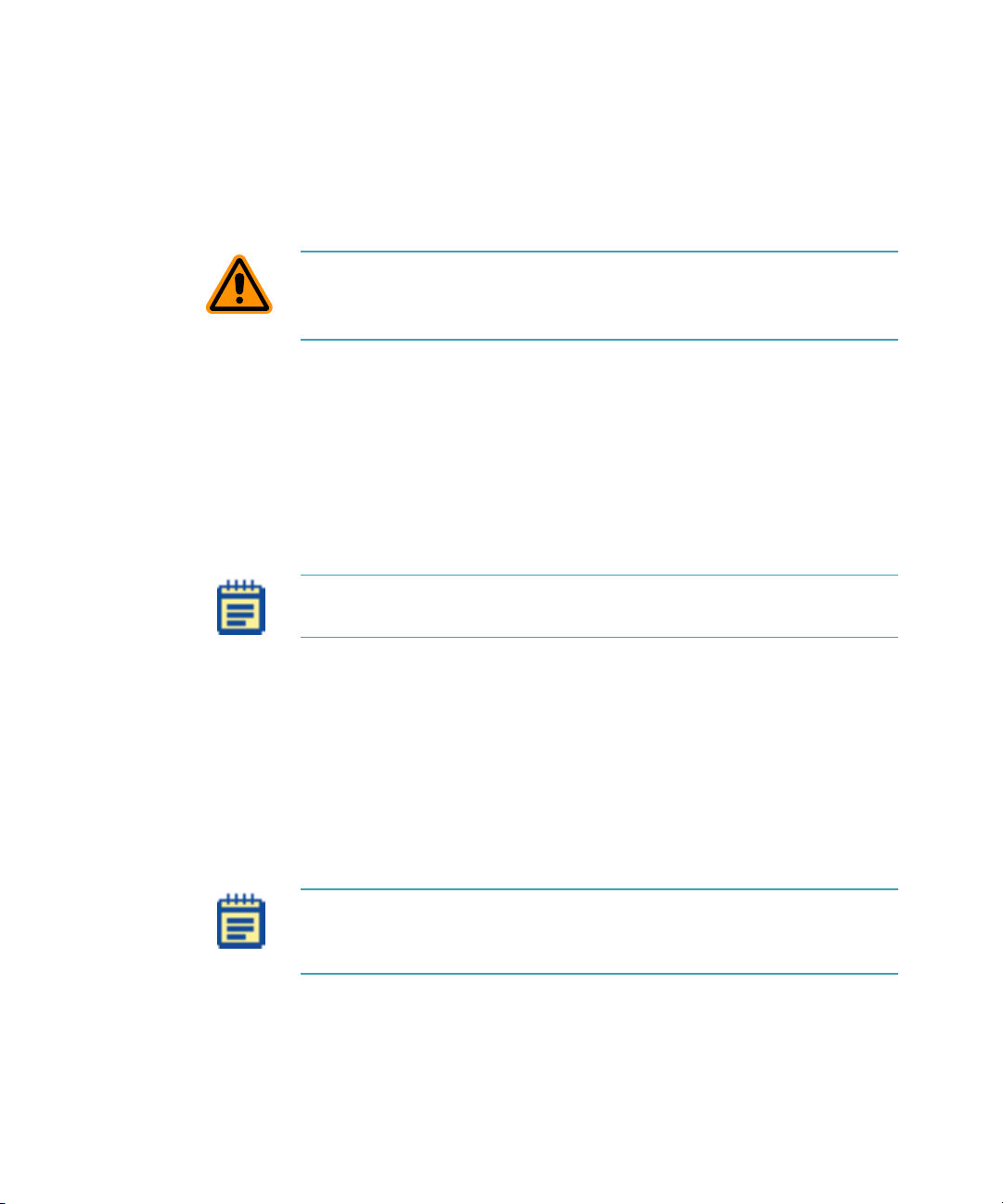
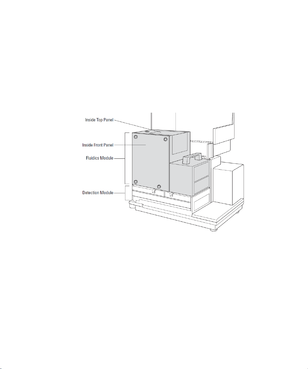
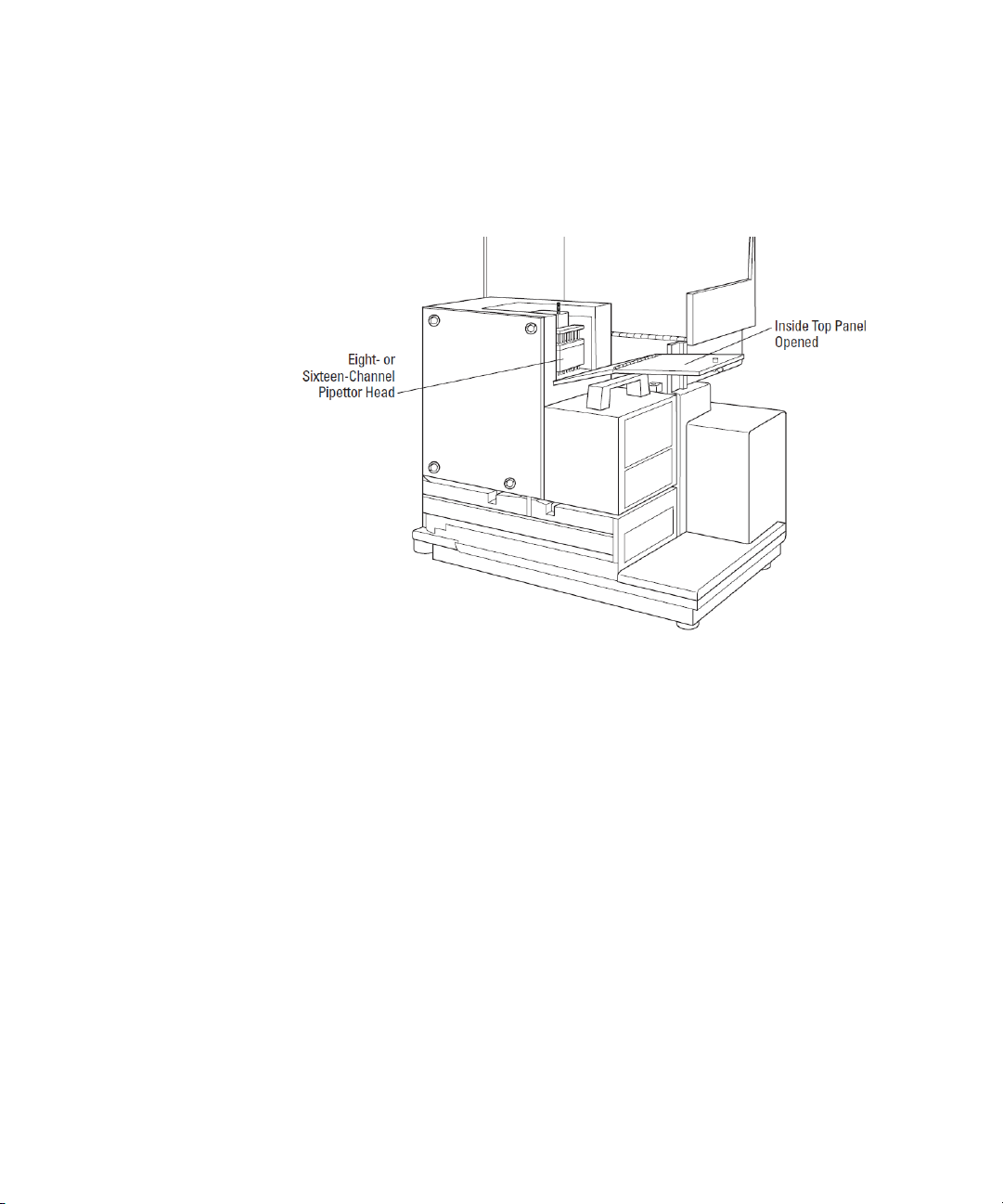
Fluidics Module
The fluidics module houses the pipettor head, several motors, and all the
fluidics components. There are two horizontally-moving carriers, one for
the pipette tip rack and the other for the compound plate. The pipettor
head moves vertically between the drawers.
The fluidics module can be opened, by service-trained users, from the
inside front panel, if necessary for maintenance, or from the inside top
panel to install or remove the pipettor head. The entire fluidics module
can be removed for maintenance or to transport the system to another
location.
Figure 1-13: Fluidics Module
Installing the Fluidics Module on page 53 or See Troubleshooting
See
Procedures on page 129.
24 0112-0127 B
Page 25
Description
Pipettor Head
The instrument is configured with an 8-channel pipettor head for use
with 96-well microplates or a 16-channel pipettor head for use with 384well microplates.
Figure 1-14: Pipettor Head
Installing the Pipettor Head on page 56.
See
The barrels on the pipettor head require periodic cleaning to remove
silicone lubricant, dust, and other miscellaneous contamination. See
Cleaning the Barrels on the Pipettor Head on page 117.
0112-0127 B 25
Page 26
FlexStation 3 Benchtop Multi-Mode Microplate Reader User Guide
Detection Module
The detection module is the lower portion of the instrument. This
module houses the reading chamber, the optics bench, several cables
and optic fibers, the power supply, the flash lamp, and other hardware.
The fluidics module attaches to the detection module and can be tilted
off to the side, to provide access to the optical system for
troubleshooting or maintenance. The detection module is contained in a
molded plastic housing, to which the top cover is attached at the back of
the instrument.
Figure 1-15: Detection Module Detail
Reading Chamber
The reading chamber includes the assay plate carriage that holds the
assay microplate in the reading chamber during read cycles. The reading
chamber can be maintained at an elevated temperature. It contains both
top and bottom read heads that can be selected in the software.
The instrument uses a plate sensor to assure that an assay plate is
present in the reading chamber before a reading begins.
26 0112-0127 B
Page 27
Description
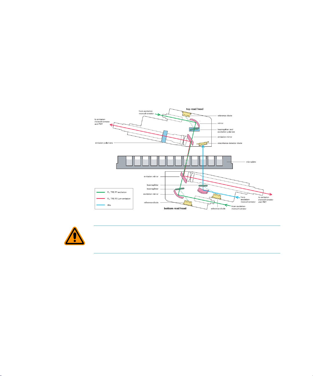
Optical System
The optical system includes a xenon flash lamp, monochromators,
excitation bandpass filters, emission cut-off filters, PMTs, and
photodiodes.
There are a number of cables and fibers that exit the optics bench and
enter the reading chamber. They are the excitation fibers (thin and black
or red, has a collar and pins), emission fibers (black and fatter, with
attached electrical cord), electrical connector to the read head (green
with brass fitting).
Figure 1-16: Optical System
CAUTION! Optical fibers are very fragile, especially the excitation fiber.
Handle cables with extreme care. Do not flex, twist, bend, or stretch the
optical cables.
0112-0127 B 27
Page 28

FlexStation 3 Benchtop Multi-Mode Microplate Reader User Guide
Computer
The FlexStation 3 instrument works as a system with the SoftMax Pro
Software. The SoftMax Pro Software must be installed on a dedicated
computer to communicate with and control instrument functions.
The instrument is equipped with an 8-pin DIN RS-232 serial port for
connecting to a computer.
SoftMax Pro Software, version 5.1 or later, is required to control the
FlexStation 3 instrument. TheFlexStation 3 instrument is not currently
supported in SoftMax Pro Software, version 6.x.
The minimum computer configuration includes a Pentium processor with
2.8 GHz, 1 GB hard drive.
See
Installing SoftMax Pro on page 63 and Setting Up the Software on
page 75.
Accessories
The following accessories are included with the system:
• Black microplate adapter (for use in reading chamber drawer)
• Compound baseplate (for use in the compound plate drawer)
• Computer cable
• Power cord, USA/Canada
• Power cord, ECI
• Fuses (2 each)
• User Guide
• Pipettor head, 8-channel and/or 16-channel
• Pipette
• Yellow plate for the respective pipettor head
• Hex key
All necessary accessories are shipped with the system.
Accessories on page 153.
Fuses are rated slow-blow (United States/Canada/Metric: 6.3 amp time
delay). See
Replacing Fuses on page 121.
Parts and
28 0112-0127 B
Page 29

Description
Cables
Molecular Devices recommends that you use high-quality, doubleshielded cables to connect the instrument to the computer. Choose
cables that meet the following requirements:
Serial Interface Cable: The serial interface cable used to connect the
instrument to the computer is a custom cable designed and built by
Molecular Devices. Use the cable supplied by Molecular Devices, or
contact Molecular Devices for specific pin-out requirements: Male DB8
to Female DB9 (custom cable made by Molecular Devices,
P/N 9000-0149).
USB Adapter Cable: Many newer computers do not have a serial port.
You can connect a serial cable between these computers and the
instrument using a USB-to-serial adapter. Molecular Devices has tested
many third-party USB-to-serial adapter cables and has found Keyspan
USA-19HS (Molecular Devices, P/N 9000-0938) to be the most reliable. It
is the only one we recommend.
Note: For specific pin-out requirements, contact Molecular Devices
Technical Support.
Microplate Adapters
The black microplate adapter fits in the assay plate carriage, in the
reading chamber drawer, to elevate standard microplates for both top
reads and bottom reads. Remove the adapter when using high-profile,
6-well, 12-well, 24-well, or 48-well microplates.
Compound Baseplate
Molecular Devices provides a metal baseplate that must be placed in the
compound plate drawer under the compounds plate to reduce stray
light.
0112-0127 B 29
Page 30

FlexStation 3 Benchtop Multi-Mode Microplate Reader User Guide
Consumables
The system consumables include:
• Microplates
• Pipette tips
One box (10 racks) of pipette tips is shipped with the system pipettor
head. See
CAUTION! Do not use parts and accessories that are not authorized by,
specified by, or provided by Molecular Devices. Using unauthorized parts
can damage the instrument.
Microplates
The FlexStation 3 instrument can accommodate standard 6-well to
384-well microplates and strip wells. When reading absorbance at
wavelengths below 340 nm, special UV-transparent, disposable or quartz
microplates allowing transmission of the deep UV spectra must be used.
Not all manufacturers’ microplates are the same with regard to design,
materials, or configuration. Temperature uniformity within the
microplate can vary depending on the type of microplate used.
Microplates supported for use in this reader are:
Read plate formats not already loaded as defaults in the SoftMax Pro
Software can be added by manually entering the dimensions using the
Plate Editor in the software.
The instrument can accommodate standard 6-well, 12-well, 24-well,
48-well, 96-well, and 384-well microplates. In Flex or other assay types
which you intend on using fluidic integration you can only use 96-well or
384-well formatted assay plates.
Parts and Accessories on page 153.
• 6-well, 12-well, 24-well, 48-well, 96-well, and 384-well standard
formats
• 96-well half area
• 96-well and 384-well low volume
30 0112-0127 B
Page 31

Description
Figure 1-17: Top View of a 96-Well Microplate
For fluorescence, Molecular Devices generally recommends black-walled,
clear-bottom microplates for bottom reading, and all-black microplates
for top reading, because they have lower backgrounds than clear plates.
For luminescence, white microplates can optimize light collection.
Note: Not all microplates are made with the same materials. Some
plastics, most notably polystyrene, have significant native fluorescence
and can cause moderate to severe background fluorescence, especially
in the UV range. If your fluorescence experiments require high
sensitivity, it might be appropriate to use microplates designed and
designated by the manufacturer to reduce background fluorescence.
0112-0127 B 31
Page 32

FlexStation 3 Benchtop Multi-Mode Microplate Reader User Guide
Pipette Tips
• For 96-well assays, Molecular Devices specifies using 96-well,
FlexStation Pipette Tips. These 200 μL tips are available in black
(P/N 9000-0911) and clear (P/N 9000-0912) versions and can be
purchased in 10 racks per box quantities.
• For 384-well assays, Molecular Devices specifies using 384-well,
FLIPR and FlexStation Pipette Tips. These 30 μL tips are available
in black (P/N 9000-0764) and clear (P/N 9000-0763) versions and
can be purchased in 50 racks per case quantities. Please ask your
local sales representative for details regarding purchasing partial
cases.
Tips are available in both black and clear options. Black tips are generally
used during fluorescence assays when auto-fluorescent properties of
clear tips can interfere with your response. Molecular Devices
recommends that you evaluate both black and clear tips during assay
development to determine which tip version is most appropriate to your
assay.
Overview of Operation
Using the FlexStation 3 instrument is a process in five stages:
• Choosing an Experiment
• Preparing the Instrument
• Preparing the Software
• Running the Experiment
• Analyzing the Data
Choosing an Experiment
• New or repeated experiment?
• Does the protocol exist?
Preparing the Instrument
• Turning on the power
• Setting temperature, if needed
• Preparing and loading tips, plates, and compounds
32 0112-0127 B
Page 33

Preparing the Software
• Entering software preferences
• Selecting instrument settings
• Defining templates, reduction parameters, and display
• Confirming hardware and software setup
Running the Experiment
• Initiating the operation (detection or fluidics plus detection)
• Saving the data file
Analyzing the Data
• Modifying the template or parameters as desired
• Saving the data file
• Analyzing the data
• Exporting data to another software application as desired
Theory of Operation
Description
parameters
This section includes the following topics:
• Instrument Design, see page 33
• Assay Read Types, see page 38
Instrument Design
Fluidics
The instrument is designed with a fluidics module that transfers liquids to
the assay plate during a fast kinetic read or before an experiment.
The fluidics module incorporates an 8-channel or 16-channel pipettor
that automatically changes tips and transfers reagents to the plate that is
read in the system. Pipette height and dispensing rate are adjustable. The
instrument can add reagents within milliseconds of a column being read,
enabling fast kinetic assays of transient responses.
As many as three compounds can be transferred from columns in a
compound plate to a single column in an assay plate, at different points
during or before the total read time.
0112-0127 B 33
Page 34

FlexStation 3 Benchtop Multi-Mode Microplate Reader User Guide
Mixing
Mixing can be accomplished in one of two ways, using either the
Trituration or Automix functions. Use of these functions are dependant
on the assay performed and the read mode used.
• Trituration is mixing of the well contents in either the compound
or assay plates. This is accomplished by fluid being alternately
aspirated from and dispensed back into a well using the pipettor.
Trituration is available only during assays that include fluid
transfer, including Flex, Endpoint, or Kinetic modes, and can be
performed in either the compound or assay plate. Within the
compound plate, trituration can be used to resuspend
compounds that might have crashed out of solution.
Alternatively, it can be used to promote prompt mixing in the
assay plate when delivering small reagent volumes for fast
kinetic cell-based assays, such as calcium mobilization.
Note: Trituration in the assay plate well may agitate cells,
causing responses not associated with the compound addition.
Assay development should be performed to determine if
trituration is necessary for the assay.
• The Automix function permits automatic shaking of the
microplate at preset intervals, thereby mixing the contents
within each well. Automix must be selected before beginning a
reading. Automix settings vary with assay type.
For Endpoint assays, enabling Automix shakes the plate for a
definable number of seconds and then reads at all selected
wavelengths.
For Kinetic assays, two types of Automix can be enabled. You
can set Automix to shake the plate for a definable number of
seconds before the initial reading or for a definable number
of seconds before each subsequent reading.
Use of Automix is strongly recommended for ELlSA and other
solid-phase, enzyme-mediated reactions to enhance accuracy.
34 0112-0127 B
Page 35

Description
Temperature Regulation
The instrument regulates the temperature of the microplate reading
chamber from 2°C above ambient to 45°C. On power up, when the
incubator is off, the temperature in the reading chamber is ambient and
isothermal. Turning on the incubator by pressing the Temp on/off key
causes the instrument to begin warming the reading chamber and the
fluidics module.
Note: The reading chamber is warmed to the set temperature.
However, the fluidics module might be lower than the set point.
The temperature set point defaults to 37°C at startup. With the incubator
on, the temperature of the reading chamber can be set and regulated
from 2°C above ambient to 45°C. Accuracy of the temperature set point
is only guaranteed if the set point is at least 2°C above ambient. If the
temperature set point is lower than the ambient temperature, the
chamber temperature remains at ambient. Temperature regulation is
controlled by heaters only and, therefore, cannot cool the temperature
to a setting lower than ambient.
Temperature regulation and control of the reading chamber is achieved
through electric heaters, a fan, efficient insulation, and temperature
sensors. The heaters are located within the instrument, which is
insulated to maintain the temperature set point. The seven sensors are
mounted inside the reading chamber and measure the air temperature
and chamber temperature. The temperature feedback closed-loop
control algorithms measure the chamber air temperature, compare it to
the temperature set point, and use the difference to calculate the
regulation of the heating cycles. This technique results in accurate,
precise control of the reading chamber temperature with a temperature
variation of the air across the entire assay plate of less than 1°C.
Temperature uniformity within the assay plate itself depends on its
design, materials, and configuration.
Note: Temperature of samples in all assay plates are affected by
evaporation.
0112-0127 B 35
Page 36

FlexStation 3 Benchtop Multi-Mode Microplate Reader User Guide
Time-Tagged Data
The FlexStation 3 instrument is a single-channel reading system.
Although the scan time is very fast (8 wells in about 1.0 seconds; 1 well in
about 50 ms), the difference in the exact time each well is read is
dependent on the number of rows selected in a column. This difference
is an important factor in fast kinetic assays.
For this reason, all readings are tagged with an exact read time, and
when multiple-well fast kinetic responses are plotted, the curves overlie
each other as plotted by the SoftMax Pro Software. If kinetic data are to
be exported, you can choose either time-interpolated data or raw timetagged data. Molecular Devices recommends that you select timeinterpolated data. This option is explained in more detail in the SoftMax
Pro user guide.
Figure 1-18: Time-Tagged Data Example
36 0112-0127 B
Page 37

Description
Optical System
The instrument uses excitation and emission filter wheels to decrease
interference by stray light, thus augmenting the wavelength selection
that is provided by the monochromators. Two independent, singlechannel reading heads can service top and bottom reading requirements.
Both the top reading head and bottom reading head support coaxial
excitation and emission beams.
The instrument’s electrical, firmware, and optical designs incorporate
many features that work together to virtually eliminate instrumentbased day-to-day and instrument-to-instrument variations in measured
fluorescence values.
For more detail of the optical design and an illustration of the optical
system, see
Detection Module on page 26.
Bottom and Top Reading
Switching to bottom or top reading capability is activated through
software. No manual positional switching of the read-head is required.
Bottom reading allows for well scanning ability maximizing the sampling
area for 6-well, 12-well, 24-well, 48-well, 96-well, and 384-well
microplates. In addition, bottom reading enables concurrent reagent
addition to monitor fast kinetic reactions such as calcium mobilization.
Availability of top or bottom reading functions varies depending on the
detection mode.
Note: Clear-bottom plates must be used for bottom reading. Bottom
reading is intended for cell-based assays.
0112-0127 B 37
Page 38

FlexStation 3 Benchtop Multi-Mode Microplate Reader User Guide
Assay Read Types
The instrument operates in three integrated fluidics/read (Flex, Endpoint,
and Kinetic) read and two read types. The Table 1-1 on page 39 compares
the types of operation and features that are available for the different
read types.
Note: This user guide describes instrument behavior for Flex read type
primarily. For instructions on other read types, see the SoftMax Pro
user guide.
Flex Reads
The fluidics module is designed to aspirate fluids from a compound
source plate and dispense them into an assay plate. Fluid transfer is
made possible with an 8-channel or 16-channel pipettor that is fully
automated, including changing the tips from a tip rack.
In Flex reads, one to eight or one to sixteen wells in one column of the
assay plate are read repeatedly for a selected total experimental time. At
a preselected point or points during that time sequence, the pipettor can
transfer up to three reagents from the compound plate to the assay
plate. The instrument continues to read at the preselected time intervals
before and after each fluid transfer. After completion of reading the
column (or partial column) for a preselected time, the instrument can
repeat this cycle with other columns. All the data is collected in one data
file represented as a 96-well or 384-well microplate.
For example, an experiment with a two-minute run time accommodates
a 96-well microplate in about 24 minutes.
Run time × Number of columns = Plate time
2 minutes × 12 columns = 24 minutes
38 0112-0127 B
Page 39

Table 1-1: Operation Modes and Features
Description
Operation
Modes
Operation
Type
Read Modes Absorbance,
System
Settings
Top read Yes or No Yes or No Yes or No Yes or No No
Bottom read Yes or No Yes or No Yes or No Yes or No Yes
Wavelength Yes Yes Yes Yes Yes
Automix
before
Automix
between
Timing No Yes No No Yes
Wells to read Yes Yes Yes Yes Yes
AutoCalibrate Yes Yes Yes Yes Yes
Compound
source
Compound
transfer
Triturate Yes Yes No No Yes
Compound
and tips
columns
AutoRead Yes Yes Yes Yes Yes
Well Scan
Editor
PMT sensitivity Yes Yes Yes Yes Yes
Endpoint Kinetic Spectrum Well Scan Flex
Fluidics +
Detection
Fluorescence,
Fluorescence
Polarization,
Luminescence,
and TimeResolved
Fluorescence
Yes Yes Yes Yes No
No Yes No No No
Yes Yes No No Yes
Yes Yes No No Yes
Yes Yes No No Yes
No No No Yes No
Fluidics +
Detection
Absorbance,
Fluorescence,
Fluorescence
Polarization,
Luminescence,
and TimeResolved
Fluorescence
Detection Detection Fluidics +
Detection
Absorbance,
Fluorescence,
Fluorescence
Polarization,
Luminescence,
and TimeResolved
Fluorescence
Absorbance,
Fluorescence,
Luminescence,
and TimeResolved
Fluorescence
Absorbance,
Fluorescence,
and
Luminescence
0112-0127 B 39
Page 40

FlexStation 3 Benchtop Multi-Mode Microplate Reader User Guide
Table 1-1: Operation Modes and Features (cont’d)
Operation
Modes
Assay plate
type
Compound
plate type
Endpoint Kinetic Spectrum Well Scan Flex
Yes Ye s Yes Ye s Yes
Yes Yes No No Yes
Endpoint Reads
In Endpoint reads, as well as in Kinetic and Flex reads, you can select
from one to four excitation/emission pairs to obtain readings for each
well of a microplate.
In Endpoint reads, one to eight or one to sixteen wells in one column of
the assay plate are delivered before starting the read. At a preselected
point or points before the read, the pipettor can transfer up to three
reagents from the compound plate to the assay plate. After reagents are
transferred, the read initiates for the entire read area. Unlike Flex, the
read area is not limited to one column at a time in an Endpoint read. All
the data are collected in one data file represented as a 96-well or
384-well microplate.
For more information on this read type, please review the appropriate
section in the SoftMax Pro user guide.
Kinetic Reads
Kinetic analysis can be performed for a total run time of up to 99 hours.
The kinetic read interval depends upon the instrument setup parameters
selected in the SoftMax Pro Software, but is limited to 2 hours and 45
minutes (165 minutes). At the end of a reading, rates are reported as
each well. Kinetic analysis has many advantages when determining the
relative activity of an enzyme in different types of assays, including the
purification and characterization of enzymes and enzyme conjugates.
In Kinetic reads, one to eight or one to sixteen wells in one column of the
assay plate can be delivered before starting the read. At a preselected
point or points before the read, the pipettor can transfer up to three
reagents from the compound plate to the assay plate. After reagents are
transferred, the read initiates for the entire read area. Unlike Flex, the
read area is not limited to one column at a time in Kinetic reads. All the
data are collected in one data file represented as a 96-well or 384-well
microplate.
For more information on this read type, please review the appropriate
section in the SoftMax Pro user guide.
40 0112-0127 B
Page 41

Description
Spectrum Reads
Spectral analysis measures across a spectrum of wavelengths (excitation
250 nm to 850 nm, emission 360 nm to 850 nm). When reading using a
specific detection mode, such as fluorescence, you can set a fixed
wavelength for excitation and scan the emission wavelengths, or set a
fixed wavelength for emission and scan the excitation wavelengths. All
spectrum readings are made using scanning monochromators.
In Spectrum reads, the fluidics module is not enabled.
For more information on this read type, please review the appropriate
section in the SoftMax Pro user guide.
Well Scan Reads
Some applications that involve the detection of whole cells in large area
tissue culture plates can require the use of Well Scan reads. As many cell
lines tend to grow in aggregates or in the edges of microplate wells, this
non-confluent growth pattern can require multiple reads at different
locations in a well.
When used with 6-well, 12-well, 24-well, 48-well, or 96-well plates, well
scanning allows maximum surface area detection for whole cell assays.
No plate adapter is used for tissue culture plates of 24 wells or less.
In Well Scan reads, the fluidics module is not enabled.
For more information on this read type, please review the appropriate
section in the SoftMax Pro user guide.
SoftMax Pro Software
The Molecular Devices SoftMax Pro Software is a highly integrated
program that can be used to:
• Control the reader
• Collect data
• Analyze data
SoftMax Pro software is easy to use, yet is powerful and flexible, and is
necessary to access the full capabilities of the FlexStation 3 instrument.
SoftMax Pro Software allows you to:
• Set Up the Reader and Software Parameters, see page 42
• Acquire Data from the Reader, see page 43
• Perform Complex Data Analysis, see page 44
0112-0127 B 41
Page 42

FlexStation 3 Benchtop Multi-Mode Microplate Reader User Guide
Set Up the Reader and Software Parameters
• Read microplates in using Flex, Endpoint, Kinetic, Spectrum, or
Well Scan read types.
Use up to four wavelengths for Flex, Endpoint, Kinetic, and
Well Scan reads.
Perform absorbance and percent transmittance readings in
the 200 nm to 1000 nm range.
Perform fluorescence readings in the 250 nm to 850 nm
range.
Perform luminescence readings in two ways: wavelength
nonspecific (all wavelengths between 360 nm and 630 nm)
or wavelength selectable (250 nm to 850 nm).
Read the whole plate or a subset of microplate wells.
Specify kinetic run times up to 99 hours.
Select your own read intervals for kinetic runs.
Specify the duration for Automix before or between reads.
Automix shakes the microplate at preset intervals, thereby
mixing the contents of each well (highly recommended for
ELISAs and other solid-phase, enzyme-mediated reactions).
Note: Automix is not intended to be used continuously for
several hours.
• Use PathCheck technology to normalize the absorbance readings
in each microplate well to a 1 cm pathlength.
• Design microplate templates to simplify data reduction.
Identify groups of wells with labels of your choice.
Identify individual wells with unique names.
Blank the entire plate, groups, or individual wells.
• Save reader settings, template formats, and data analysis
parameters as assay protocol files and recall them for later use.
Rapid reader and analysis setup for repeated assays.
Uniform analysis for equivalent microplates.
• Turn the incubator on or off to control the temperature in the
read plate drawer.
42 0112-0127 B
Page 43

• Integrate fluid transfer with Endpoint, Kinetic, and Flex reads.
Transfer fluid during the experiment for fast kinetic
fluorescence, luminescence, and absorbance assays.
Transfer fluid before the beginning of an experiment for
endpoint and kinetic applications.
Define the reagent source and tip columns to be used for
each fluid transfer.
Optimize dispense parameters by specifying the volume,
height, and speed of addition.
Specify the number of strokes used during Trituration to mix
the contents of the source and read plates. Trituration uses
the pipettor to mix the contents of a well by aspirating and
dispensing, for both the source and read plates.
Acquire Data from the Reader
• Pre-read microplates.
• Analyze kinetic and spectrum data as it is collected.
• Save data files for in-depth analysis at a later time.
• Save multiple microplates with individual template and data
analysis parameters in one or more experiments in a single data
file.
• Display data on screen.
Raw values, reduced number, or raw values with reduced
number.
Raw microplate data in a microplate format.
Ranged data as integers from 0 to 9 in a microplate format.
Threshold data as being above, below, or between set limits
in a microplate format.
Grayscale data in eight shades of gray corresponding to high
and low limits in a microplate format.
Kinetic or spectrum plots of all microplate wells.
Enlarge the display of individual well plots and overlay
multiple well plots.
Description
0112-0127 B 43
Page 44

FlexStation 3 Benchtop Multi-Mode Microplate Reader User Guide
Perform Complex Data Analysis
• Calculate maximum kinetic rates on non-linear data.
• Assign plate, group, or sample blanks.
• Customize data analysis for each group in the template.
• Create graphs with multiple plots.
• Pick from nine curve-fitting routines.
• Analyze unknown samples against a standard curve.
• Analyze and compare data within a plate, between plates, and
between experiments.
• Customize your print formats.
Print all or individual sections of the data file.
Define and print a report containing only selected sections.
Customize the order of data file sections.
• Export data in tab-delimited ASCII format.
For complete information on the current SoftMax Pro Software, see the
SoftMax Pro User Guide and Formula Reference Guide included with
your FlexStation 3 instrument.
44 0112-0127 B
Page 45

Description
User Interface
This section briefly presents the basic features of the SoftMax Pro
Software user interface. More instructions regarding how to use the
interface appear throughout these instructions during relevant steps.
You can control the instrument by using either buttons and icons in the
windows and along the tool bars, or by using the menus. You can use
either your mouse or keystrokes to make selections.
Note: For complete details about the SoftMax Pro Software and user
interface, refer to your SoftMax Pro User Guide.
Figure 1-19: Plate Section, Flex Mode
0112-0127 B 45
Page 46

FlexStation 3 Benchtop Multi-Mode Microplate Reader User Guide
The Status bar allows you to monitor instrument status and access
several functions with the click of a button. You can verify
communication with SoftMax Pro, and monitor the reading chamber
temperature. The Status bar also provides buttons used to begin a
reading, open the Incubator dialog box, shake the microplate (Automix),
and open or close the instrument drawers. The Status bar can be hidden
by selecting Hide Status from the View menu.
Figure 1-20: SoftMax Pro Software Status Bar
The following icons are present in the Status bar and are used to set up
the instrument or interact with it during operation.
Note: Different Molecular Devices systems have different icons.
Table 1-2: SoftMax Pro Software Status Bar Icons
Icon Description
The Instrument Status icon provides visual confirmation that
SoftMax Pro is communicating with the instrument. Doubleclick this icon to display the Preferences dialog.
The temperature icon displays the current temperature
inside the instrument. Click this icon to display the
Preferences dialog.
Click to begin reading. It changes to Stop during a reading.
Clicking this button also closes any open drawers.
Click the Incubator button to open the Incubator dialog to
change temperature settings.
Click the Automix button to manually shake the assay plate.
Note: The manual shaking that occurs when you click this
button differs from the Automix that can be selected as an
instrument setting within the protocol settings.
Click the Drawer button to open or close the reading
chamber drawer.
46 0112-0127 B
Page 47

Description
One SoftMax Pro Software file contains at least one experiment, and can
contain a section for Notes and one or more Plates. You can enter Notes
and edit Plates using the tool bars shown below.
Figure 1-21: SoftMax Pro Software Plate Section Toolbar
The following icons appear on the Plate Section tool bar.
Table 1-3:
Icon Description
Double-click the Plate icon to open the Plate section in a new
window.
Double-click the Name of Plate icon to open the Section
dialog.
Click the Settings button to open the Instrument Settings
dialog for this plate.
Click the Template icon to open the Template dialog, where
you can create or edit the template. This is used to setup
groups for defining areas of the assay plate.
Click the Reduction icon to configure settings for data
analysis and graph reduction.
Click the Display icon to open the Display dialog and change
your display properties.
Click the Graph icon to enlarge sections of the display into
graphic form.
Click the Mask icon to mask selected wells.
Click the Printer icon to include or exclude a section from a
printed report.
The SoftMax Pro Software provides other icons and tool bars. For
example, you can keep Notes on the experiment in the Notes section.
Groups are also contained in experiments when you define a template.
You can create Graph sections as desired. For details, see your SoftMax
Pro Software User Guide.
0112-0127 B 47
Page 48

FlexStation 3 Benchtop Multi-Mode Microplate Reader User Guide
48 0112-0127 B
Page 49

Installation
2
This chapter provides information about how to install the FlexStation 3
instrument in your laboratory. Installation must be done by qualified
Molecular Devices personnel or a service-trained user.
CAUTION! The following procedures must be completed by a servicetrained user. Do not attempt the installation procedures if you have not
been trained properly by appropriate Molecular Devices personnel.
The following sections describe the installation procedure:
• General Precautionary Information, see page 49
• Unpacking the System, see page 50
• Installing the Fluidics Module, see page 53
• Installing the Pipettor Head, see page 56
• Setting Up the Computer, see page 61
• Connecting the Cables, see page 61
• Installing the Drawer Adapters, see page 62
• Installing SoftMax Pro, see page 63
General Precautionary Information
WARNING! Always make sure the power switch on the instrument is
in the OFF position and remove the power cord from the back of the
instrument before any installation or relocation of the system.
WARNING! Do not install or operate the system in an environment
where potentially damaging liquids or gases are present.
0112-0127 B 49
Page 50

FlexStation 3 Benchtop Multi-Mode Microplate Reader User Guide
CAUTION! Do not touch or loosen any screws or parts other than those
specifically designated in the instructions. Doing so might cause
misalignment and will void the system warranty.
CAUTION! Do not attempt to assemble or disassemble the instrument
with the pipette tips or compound and read plates in place. Spillage or
damage to the pipette tips, plates, or the instrument can occur.
Unpacking the System
This section provides instructions on how to unpack the system safely.
WARNING! The instrument weighs approximately 50 pounds and
should be lifted with care. To prevent injury, use at least two people to
lift the instrument.
Each FlexStation 3 instrument comes with the following components.
• Fluidics module and accessories
• Detection module (main instrument body) in housing
• Computer (can be user-supplied)
• Computer monitor (can be user-supplied)
• SoftMax Pro Software package
Please retain the cartons, all boxes, and any significant packing materials.
If the system needs to be moved to a different location, use the original
packing materials and cartons whenever possible. If the cartons have
been damaged in transit, it is particularly important that you retain them
for inspection by the carrier in case there has also been damage to the
instrument.
As you unpack the system components, examine the packing list that
accompanies the system to be sure all items are present.
50 0112-0127 B
Page 51

Installation
Unpacking the Fluidics Module and Accessories
1. Remove the fluidics module from the cardboard box inside the
wooden crate and take it out of the protective bag. Set it in a safe
place.
2. Remove the box (containing the pipettor head) and the bags of
accessories.
3. Open the accessories bags and remove cables and the hex key.
You will need them later in the assembly procedure.
4. Set packaging aside.
Unpacking the Detection Module
Note: Keep the system in a location that is dedicated to its use, on a
level surface, away from direct sunlight, dust, drafts, vibration, and
moisture.
Tools Needed
• Hex key, 3/32 inch ball drive, L (provided)
• Phillips screwdriver (not provided)
To unpack the detection module:
1. Use two people to unlatch the midsection of the crate (on top
and bottom) and then move that midsection aside. Due to the
size of the crate, this step requires two people.
2. Slide the plastic bag enclosing the instrument out of the way,
around the base of the detection module.
3. Use two people to reach inside the bag and under the
instrument and then lift the instrument out of its shipping tray
and place it on the bench.
WARNING! The instrument weighs approximately 50 pounds
and should be lifted with care. To prevent injury, use at least
two people to lift the instrument.
4. Set the shipping materials out of the way.
0112-0127 B 51
Page 52

FlexStation 3 Benchtop Multi-Mode Microplate Reader User Guide
Removing the Shipping Screws
1. Locate the two stainless steel shipping screws under the front
flange of the detection module that hold down the cover of the
instrument.
Figure 2-1: Location of Shipping Screws
2. Use the 3/32 inch hex key to unscrew the shipping screws. It
might be necessary to move the instrument to the front of the
bench to reach the screws from below. The screws remain
attached to the base.
3. Press the latch in the handle and pivot the top cover up and
back.
52 0112-0127 B
Page 53

Installing the Fluidics Module
After removing the shipping screws and opening the top cover, you can
see the location for the fluidics module hardware. There is a hinged
flange (metal plate) to the left side of the exposed reading chamber.
There are also two quarter-turn fasteners (Zeus screws) attached to the
flange, and two locating pins near the middle of the reading chamber.
Installation
Figure 2-2: Positioning the Fluidics Module
CAUTION! To avoid damage to the instrument, follow these instructions
and any instruction labels on the instrument exactly.
WARNING! Do not remove cover until power is disconnected. Do not
operate instrument unless all covers are in place.
0112-0127 B 53
Page 54

FlexStation 3 Benchtop Multi-Mode Microplate Reader User Guide
To install the fluidics module:
1. Grasp the handle on the fluidics module and use a second person
to help to lift the module into position over the detection
module.
2. Tilt module up at about 90° and have one person hold it in
position while the other person aligns the quarter-turn fasteners
in the flange to the holes in the bottom of the fluidics module.
3. Connect the quarter-turn fasteners to the bottom of the fluidics
module and lock the fasteners into place.
4. Attach the restraining cable from fluidics module to the rightmost mounting tab on the top cover of FlexStation 3 instrument.
The restraining cable comes attached to the fluidics module.
Figure 2-3: Restraining cable attached to the fluidics module
Attach the other end of the restraining cable the right-most
mounting tab on the top cover.
Figure 2-4: Restraining cable attached to the top cover
54 0112-0127 B
Page 55

Installation
A finished installation should look like Figure 2-5.
Figure 2-5: Restraining cable installation finished
The restraining cable for the fluidics module prevents the
module from pivoting too far, and prevents the accidental
detachment of the serial communication cable. The restraining
cable also holds the module in the open position so that the
instrument can be serviced without first detaching the
communication or power cable.
5. With the fluidics module tilted back, connect the 15-pin sub-D
electrical connector into the communication port on the far
bottom edge of the fluidics module. It must be aligned properly
to fit.
Note: The labels on the fluidics connector (Fluidics Connector)
and near the communication port (Connect Fluidics Here) help
identify these ports.
Figure 2-6: Fluidics connection labels
6. Press the connector in firmly.
0112-0127 B 55
Page 56

FlexStation 3 Benchtop Multi-Mode Microplate Reader User Guide
7. Use your fingers to lightly tighten the two communication port
thumbscrews.
Molecular Devices recommends tightening the thumbscrews on
the Sub-D connector to firmly attach the communication and
power cable to the connector on the fluidics module. This
prevents the accidental disconnection of the cable from the
fluidics module due to vibration of the FlexStation 3 instrument.
8. Ensure that all cables and wires are tucked out of the way.
9. Gently lower the fluidics module by the handle down over the
detection module and onto the locating pins.
CAUTION! Be careful when lowering the fluidics module that
you do not trap or compress any of the optical fibers coming up
from the detection module.
10. Ensure that the fluidics module is firmly seated on the detection
module.
Installing the Pipettor Head
After you install the fluidics module, you can place the pipettor head into
the fluidics module. Use this same procedure for both the 8-channel and
16-channel pipettor heads.
The barrels on the pipettor head require periodic cleaning to remove
silicone lubricant, dust, and other miscellaneous contamination. See
Cleaning the Barrels on the Pipettor Head on page 117.
CAUTION! To avoid damage to the instrument, follow these instructions
and any instruction labels on the instrument exactly.
1. Remove the pipettor head from its carton.
CAUTION! During the pipettor installation process, make sure
that the pipettor cap remains on the 16-channel pipettor. This
minimizes any potential damage to the pipettor nose cones.
56 0112-0127 B
Page 57

Installation
2. Turn the quarter-turn fastener on the inside top cover and then
unfold the cover off the fluidics module.
Figure 2-7: Opening the Inside Top Cover
0112-0127 B 57
Page 58

FlexStation 3 Benchtop Multi-Mode Microplate Reader User Guide
3. Hold the pipettor head in one hand and the round, black, 14-pin
connector in the other.
4. Move the pipettor head into its approximate position under the
z-stage plate and red mounting knob.
5. Maneuver the cable down toward the back of the cavity and
align the connector over the receptacle.
6. Press the connector in place and screw down the black outer
collar over the pins.
Figure 2-8: Securing Spiral Cord to Hook
58 0112-0127 B
Page 59

Installation
7. Press the first four loops of white spiral cord onto the coil hook in
the upper left corner of the top panel opening. This secures the
cable up out of the way of the pipettor head when it moves
about in the fluidics module during operation.
Figure 2-9: Positioning Pipettor Head
8. With one hand, pull up on the red knob.
9. With the other hand, align the metal plate at the back of the
pipettor head, with the screw hole and the two locating pins,
underneath the red knob.
10. Slide the plate up into place.
11. Screw down the red knob, securing the pipettor head so that it
hangs in place from the black bar.
CAUTION! Tighten the red knob (the pipettor retaining nut) as
firmly as possible.
0112-0127 B 59
Page 60

FlexStation 3 Benchtop Multi-Mode Microplate Reader User Guide
12. Remove the cap at the completion of the pipettor installation.
CAUTION! Do not discard the nose cone cap. Always store the
pipettor with the nose cone cap on.
The pipettor head is now installed (see Figure 2-10).
Figure 2-10: Pipettor Head Installed
13. Fold the inside top panel back over the pipettor head and lock
the quarter-turn screw in place.
14. Bring the top cover back over the fluidics module and snap it into
place at the handle on the detection module. Make sure the
latch clicks shut.
60 0112-0127 B
Page 61

Setting Up the Computer
Set up the computer and monitor, according to the instructions that
come in their packaging. Place them close to the instrument on the
bench.
The power cords for the computer and monitor are provided in the
computer packaging. Connect them to the computer hardware as
described in
power cables to the power outlet at the wall.
CAUTION! Do not attach the computer to a power outlet until after the
computer and the instrument are connected.
Connecting the Cables
After the instrument is assembled and the computer is set up, you can
connect computer cable and the power cord.
CAUTION! Make sure that all assembly is completed before connecting
the power cord to a power outlet.
Installation
Connecting the Cables on page 61. Do not connect the
Figure 2-11: Computer Cord and Power Cord Locations
1. Locate the instrument power cord (P/N 4400-0002) and the
computer serial cable (P/N 9000-0149) in the FlexStation 3
instrument accessories kit.
0112-0127 B 61
Page 62

FlexStation 3 Benchtop Multi-Mode Microplate Reader User Guide
2. Insert the 8-pin DIN round end of the serial cable into the RS-232
serial port receptacle on the back panel of the instrument.
3. Attach the other end to the COM serial port to the back of the
computer.
4. Insert the female end of the power cord into the power
receptacle at the rear of the instrument.
5. Connect the instrument power cord to a grounded power outlet
of the appropriate voltage.
Molecular Devices recommends that you use a surge protector
between the power cord and the grounded power outlet.
6. Connect the computer hardware power cords to similarly
grounded power outlets.
CAUTION! Make sure that no cables run beneath the instrument. Leave
at least three inches between the back of the instrument and the
nearest objects or surfaces to ensure proper ventilation and cooling.
Installing the Drawer Adapters
The drawer adapters include the black microplate adapter and metal
compound baseplate.
Microplate Adapter Installation
To bottom read or top read a standard 96-well or 384-well microplate,
you must install the black microplate adapter in the reading chamber
drawer. The black adapter elevates the plate in the drawer.
CAUTION! Incorrect insertion or removal of the adapter can cause
damage to the microplate drawer or to the pipettor head.
1. Turn the power to the instrument on.
2. Press the Reading Chamber button on the front panel. The
reading chamber drawer opens.
3. Hold the adapter so that its cutout corner is facing the front left
corner of the drawer, and then lower the adapter into the read
plate drawer.
62 0112-0127 B
Page 63

Compound Baseplate Installation
The metal compound baseplate installs in the bottom of the compound
plate drawer.
1. Turn on the power to the instrument.
2. Press the Reagents button on the front panel. The compound
3. Lower the baseplate into the compound drawer with its cutout
CAUTION! Always remove any microplates and adapters from the
instrument drawers before moving the instrument or before any service
or maintenance procedures. Microplates and adapters can easily
become jammed inside the instrument, causing damage. For
instructions on removing adapters, see
on page 120.
Installing SoftMax Pro
Install the SoftMax Pro Software on the computer according to the
instructions in the SoftMax Pro Software User Guide.
Installation
plate drawer opens.
corner facing the front left corner of the drawer.
Using the Microplate Adapters
0112-0127 B 63
Page 64

FlexStation 3 Benchtop Multi-Mode Microplate Reader User Guide
64 0112-0127 B
Page 65

Operating Procedures
This chapter explains how to start up the system and how to use the
control panel and the SoftMax Pro Software to configure instrument
settings, define experiment protocols, and run an analysis, as described
in the following sections.
• Overview, see page 66
• Starting Up the System, see page 67
• Setting the Temperature, see page 72
• Setting Up the Software, see page 75
• SoftMax Pro Software Parameters, see page 78
• SoftMax Pro Software Parameters for Fluid Transfer, see page 86
• Other Software Settings, see page 99
• Reading a Microplate, see page 99
• Shutting Down the System, see page 103
• Optimizing Fluorescence Assays, see page 103
• Optimizing Time-Resolved Fluorescence Assays, see page 110
• Optimizing Fluorescence Polarization Assays, see page 111
• Optimizing Luminescence Assays, see page 112
3
Note: The information in this chapter assumes that the instrument and
computer are properly installed and connected. See
page 49.
0112-0127 B 65
Installation on
Page 66

FlexStation 3 Benchtop Multi-Mode Microplate Reader User Guide
Overview
The following list provides an overview of the basic operating procedures
required for using the system.
1. Turn on the power to the instrument and then the computer, if
they are not already on, and then start the SoftMax Pro
Software. See
2. View the control panel and note the temperature inside the
reading chamber, and use the control panel on the front of the
instrument to turn on the incubator, if it is required by your
experiment. It can take a while for the temperature to stabilize,
so do this before configuring other instrument parameters. See
Setting the Temperature on page 72.
Note: Incubator settings can also be set using the SoftMax Pro
Software.
3. Use the SoftMax Pro Software to configure the read mode, type
of analysis, template, and so on, as desired. You can also create
sections, such as Notes and Plates, as needed in the Experiment
section of the software window. See
page 75, SoftMax Pro Software Parameters on page 78, SoftMax
Pro Software Parameters for Fluid Transfer on page 86, and
Other Software Settings on page 99.
4. Load the prepared pipette tip rack and microplates into their
drawers. Use drawer adapters as needed. See
Microplates on page 99.
5. Use the SoftMax Pro Software to start the reading. See
the Reading on page 100.
Starting Up the System on page 67.
Setting Up the Software on
Loading Tips and
Starting
66 0112-0127 B
Page 67

Starting Up the System
Normally, you do not need to switch off power at the end of the day. If
the system will not be used for more than a day, it is best to turn off the
instrument. Use the following procedure only if the system has been
switched off.
Note: These instructions assume that the SoftMax Pro Software has
been installed and you are ready to begin an experiment. For software
installation instructions, see the SoftMax Pro Software User Guide.
1. Locate the power switch on the back of the instrument.
Operating Procedures
Figure 3-1: Power Switch Location
2. Press the rocker switch to the ON position (I).
The instrument automatically performs diagnostic checks to
ensure that it is functioning correctly. All three drawers open and
close. After about four minutes, the control panel displays the
temperature inside the reading chamber. The reading chamber
drawer automatically opens.
0112-0127 B 67
Page 68

FlexStation 3 Benchtop Multi-Mode Microplate Reader User Guide
After about five minutes, the instrument is warmed up and
ready.
Figure 3-2: Control Panel Ready
Note: No set point temperature appears at this time, since the
incubator has not been turned on.
3. Turn on the host computer and allow Windows to start up.
4. Double-click the SoftMax Pro Software icon to start the program.
Note: If you get an error message while the software is starting
up, see Troubleshooting Procedures on page 129.
The SoftMax Pro Software opens with an Untitled window in Flex mode,
with a default template selected.
68 0112-0127 B
Page 69

Operating Procedures
Figure 3-3: SoftMax Pro Software New Untitled Window
• For users new to SoftMax Pro Software:
If you are new to SoftMax Pro Software, familiarize yourself with
the software by reading about the default protocol, and running
the tutorial described in this window. Also, refer to the SoftMax
Pro Software User Guide.
• For users familiar with SoftMax Pro Software:
If you are already familiar with SoftMax Pro Software, you can
close the Notes section and open the Plate section. You are now
ready to begin setting up your experiment protocols.
For information on adjusting software settings, see
Setting Up the
Software on page 75.
0112-0127 B 69
Page 70

FlexStation 3 Benchtop Multi-Mode Microplate Reader User Guide
Using the Control Panel
You can interact with the instrument by using the buttons on the
instrument control panel. All control panel button functions can also be
controlled in the software.
Figure 3-4: Detail of Control Panel with LCD
The following tables describe the indicators and buttons in the control
panel.
Table 3-1: Indicators in the Control Panel
Indicator Description
The actual°C provides the actual temperature inside the
reading chamber at any given time.
The set pt°C provides the set point temperature you select
for the current experiment. This number is displayed only
when the incubator is on.
70 0112-0127 B
Page 71

Table 3-2: Buttons in the Control Panel
Button Description
the Temp on/off button enables or disables the incubator.
When the incubator is on, both the set temperature and
measured internal temperature are shown on the front panel
LCD display.
The arrow buttons allow you to enter a set point for the
temperature in the instrument reading chamber. Press these
buttons to adjust the temperature up or down, starting at
the previous temperature setting, or the default of 37°C if no
setting has been made. Press either arrow once to increase
or decrease the temperature shown in the display by an
increment of 0.1°C; press and hold to scroll the temperature.
The tip rack button opens or closes the tip rack drawer.
The reagents button opens or closes the compound plate
drawer.
The reading chamber button opens or closes the reading
chamber drawer. Whether or not the drawer remains open
depends on the incubator setting.
• If the incubator is off, the drawer remains open.
• If the incubator is on, the drawer closes after
approximately 10 seconds to assist in maintaining
temperature control within the microplate chamber.
Operating Procedures
Note: If the feature is selected in Instrument Setup, the
drawer remains closed after the assay plate reading.
0112-0127 B 71
Page 72

FlexStation 3 Benchtop Multi-Mode Microplate Reader User Guide
Setting the Temperature
If you want an elevated temperature within the instrument for your
experiment, turn on the incubator at least 30 minutes before you plan to
start plate reading. Up to 30 minutes can be required for the
temperature within the chamber to reach the set point. Turning on the
incubator and choosing a temperature set point can be done using the
software or the front panel of the instrument.
The instrument will operate with a reading chamber temperature from
2°C above ambient to 45°C. The temperature cannot be regulated at a
set point that is outside this range.
Note: It is possible to enter a temperature setting that is outside the
operational range, either with the software or with the control panel.
However, the instrument will not respond with a temperature outside
the allowable range.
Displaying the Temperature
Two temperatures are displayed in the LCD on the control panel.
Figure 3-5: Temperature Control and Display
The upper reading is the temperature measured inside the reading
chamber. When the incubator is off, this upper number is the ambient
temperature. The lower reading is the set point, that is, the temperature
you desire for the current experiment, and it is displayed only when the
incubator is enabled.
72 0112-0127 B
Page 73

Operating Procedures
Setting the Temperature with the Control Panel
To enable the incubator, press the Temp on/off button on the control
panel. The display indicates that temperature control is on by displaying
numbers in the lower half of the LCD. The instrument sets the reading
chamber to the default temperature, 37°C.
Figure 3-6: Temperature Control Enabled
To change the temperature set point, press the up or down arrow keys
until the desired temperature set point appears on the display.
The reading chamber temperature is maintained at the set point until
you disable temperature control by touching the Temp on/off button
again. When the incubator is off, the temperature within the reading
chamber returns to ambient.
Note: If the power is shut off to the instrument for any reason, you
need to turn on the incubator again and allow sufficient time (at least
10 minutes) for the control algorithm to fully stabilize the reading
chamber temperature.
0112-0127 B 73
Page 74

FlexStation 3 Benchtop Multi-Mode Microplate Reader User Guide
Setting the Temperature with SoftMax Pro Software
You can turn on the incubator with software by selecting Incubator from
the Control menu. You can also click the Incubator button on the
instrument Status bar.
Figure 3-7: Incubator Button
The Incubator dialog appears.
Figure 3-8: Incubator Dialog
You can leave the temperature setting at the default value or you can
type a different value into the Temperature field.
Note: The incubator setting is independent of the protocol being run.
Running an experiment does not automatically select the temperature
set point. After a reading, the temperature set point, range, and
average actual temperature are recorded in the saved file.
74 0112-0127 B
Page 75

Setting Up the Software
Use the following procedure to check the instrument status and settings.
1. Observe the Instrument Status icon in the left corner of the
SoftMax Pro Software Status bar. The icon is purple when the
SoftMax Pro Software correctly recognizes the instrument.
2. Observe the temperature displayed in the Temperature display
field.
v
Figure 3-9: Instrument Status Bar
If there is a red X in front of the Instrument Status icon, if there is
no temperature in the Temperature display field, or if you see
other problems, you might need to adjust instrument
preferences.
To adjust instrument preferences, follow Step 3 through
Otherwise, skip to Step 6.
3. Click Edit > Preferences or double-click on the instrument icon.
The Preferences dialog appears.
Operating Procedures
Step 5.
Figure 3-10: Preferences Dialog
4. Make sure that the serial port setting agrees with the actual port
the computer cable (RS-232 cable) is connected to. This is
generally Com1.
0112-0127 B 75
Page 76

FlexStation 3 Benchtop Multi-Mode Microplate Reader User Guide
5. Make sure that the serial comm speed is 9600 Baud.
Note: After you read an assay plate in Flex mode, the serial
communication speed changes to 57600 Baud.
If you have correctly configured the settings in the Preferences
dialog as described in
Step 3 through Step 5 and you are still
observing problems (a red ‘X’ over the Flex icon, no temperature
in the temperature display box, or other problems), then you
must take further steps to establish communication between the
computer and the instrument, or to resolve a different
instrument problem. See Troubleshooting Procedures on
page 129.
6. The SoftMax Pro application defaults to Flex mode every time
you start the software. You can confirm this mode, if desired, by
clicking Control > Instrument Setup or click the Settings button
on the Plate section tool bar to view the Instrument Settings
screen.
Figure 3-11: Settings Button
Figure 3-12: Instrument Settings Dialog
76 0112-0127 B
Page 77

Operating Procedures
7. Make sure that the Flex button on the right is selected.
Note: You can select a different read type from the Instrument
Settings screen by clicking on one of the other four buttons at
the top of the window. The rest of these instructions assume
you are remaining in Flex mode.
8. Click OK to return to the Untitled window.
Figure 3-13: Untitled Window in Flex Mode
9. Before continuing with other software settings, create or edit the
Plate sections you will need. To create more Plate sections, click
Experiment > New Plate.
If you want to create a plate section with settings identical to a
particular existing plate section, select that plate section and
then click Edit > Duplicate.
Double click on the word Plate in the Plate Section tool bar to
open a dialog to name the Plate section. See the SoftMax Pro
Software User Guide.
0112-0127 B 77
Page 78

FlexStation 3 Benchtop Multi-Mode Microplate Reader User Guide
SoftMax Pro Software Parameters
In addition to the settings discussed in Setting Up the Software on
page 75, there are several other parameters to select when reading a
microplate. Listed under Setup in the SoftMax Pro Software, these reader
parameters can and should be adjusted to get the best data from your
particular assay. Some of the parameters are discussed here in the
FlexStation 3 instrument User Guide, and they are discussed in more
detail in the SoftMax Pro Software User Guide. All possible combinations
of type, mode, and parameter are not presented here, but Molecular
Devices technical support is always available to help you achieve the best
possible results.
Refer to the following sections for considerations when setting up for a
specific read.
• Read Types, see page 79
• Read Modes, see page 79
• Wavelengths, see page 80
• Sensitivity, see page 80
• Timing, see page 81
• Assay Plate Type, see page 82
• Wells to Read, see page 83
• Automix, see page 84
• AutoCalibrate, see page 85
• Settling Time, see page 85
• AutoRead, see page 85
78 0112-0127 B
Page 79

Operating Procedures
Read Types
Choose from five read types. The reading can occur in a each well of a
microplate unless otherwise noted.
• Flex: Data is collected over a specified period of time at regular
intervals and uses integrated fluid transfer to delivery reagents
while the wells are being read.
• Endpoint: A single reading is taken. Fluid transfer can occur only
before the read.
• Kinetic: Data is collected over a specified period of time at
regular intervals and fluid transfer can occur only before the first
read.
• Spectrum: The scanning monochromator is used to take readings
of the same sample at many different wavelengths within the
range specified. No fluid integrated transfer is available.
• Well Scan: Multiple readings are taken in different areas of each
well in a 6-well to 96-well microplate. No integrated fluid transfer
is available.
Read Modes
The detection modes available for each experiment will vary depending
on the read type selected. Select from up to five possible Read Modes:
• Fluorescence (RFUs)
• Absorbance (ODs)
• Luminescence (RLUs)
• Time-Resolved Fluorescence (RFUs)
• Fluorescence Polarization (RFUs)
If bottom reading is possible for the selected read mode, a check box
appears in the window that says Well Bottom Read. If you want to read
through the bottom of a clear-bottom plate, select the Well Bottom
Read check box.
0112-0127 B 79
Page 80

FlexStation 3 Benchtop Multi-Mode Microplate Reader User Guide
Wavelengths
Up to four wavelengths can be read per well. Although the arrows open a
window showing the six most commonly-used wavelengths, the tunable
monochromator allows any excitation or emission wavelength to be
entered between a certain range for the particular read mode. In
addition to an emission monochromator, fluorescent-quality cutoff filters
help reduce background signal.
You can either manually choose from 15 emission filters or allow the
software to choose which long pass emission filter to use based on the
excitation wavelength. See
Settings on page 109.
Table 3-4: Emission Cutoff Filter Default
Sensitivity
Adjust sensitivity either by varying the number of readings that are
performed in each well or by changing the PMT sensitivity (voltage). In
general, a higher number of readings results in better reader precision. In
fluorescence intensity reading, the sample can photobleach if a high
number of flashes are used, so if the plate will be re-read (especially for
kinetic assays or multiwavelength reads), Molecular Devices
recommends using 10 readings or fewer. During Flex mode, Molecular
Devices recommends that you begin with 6 readings to supply enough
light for these fast kinetic assays. For low-signal endpoint assays, such as
some FP or TRF assays, 100 readings per well can be optimal.
The Automatic PMT sensitivity setting allows the reader to adjust the
PMT voltage automatically for varying signals coming from samples on
the plate. In modes that allow manual setting of the PMT, a setting of
High is best for low signal assays, including assays that require Flex mode.
The PMT sensitivity is not adjustable for all read types, including Kinetic
and Flex reads.
Note: Increasing the number of reads also increases the total read
time.
Figure 3-14: Sensitivity Settings
80 0112-0127 B
Page 81

Operating Procedures
The photomultiplier tube (PMT) is a photon detector that detects light,
through the use of photoemission and successive instances of secondary
emission, to produce enough electrons to generate a strong signal.
Timing
The Timing setting depends on several settings which appear after it in
the list. To obtain the minimum read interval, you must return to Timing
after completing all the settings.
To adjust the Timing for readings, enter the total run time and the time
interval between readings.
Figure 3-15: Timing Settings
To change the default values, click in the appropriate box and then type
the desired run time or interval. The acceptable run time range is from
0 seconds to 1000 seconds.
After you have entered the values, the total Number of Reads calculated
by the instrument is displayed automatically. Depending on what
sensitivity you have selected in the sensitivity settings, the Minimum
Interval and the Minimum Run Time automatically adjusts. The Minimum
Interval is also dependent on the Compound Transfer settings and the
number of wells to be read per column.
If you select a time that is out of range or an inappropriate interval, an
error message appears at the bottom of the window.
Figure 3-16: Timing Error Message
0112-0127 B 81
Page 82

FlexStation 3 Benchtop Multi-Mode Microplate Reader User Guide
Assay Plate Type
Assay Plate Type determines the alignment of the read head with respect
to the microplate. For 384-well microplates, it is important that the
correct assay plate be chosen to match the microplate that the reader
will read. If the microplate you are using is not listed in the selection, a
new plate type can be added under the Plate menu option Edit Plate
Type.
Figure 3-17: Assay Plate Types
Note: If you change the Assay Plate Type setting for a Plate section, the
well assignments stored in the previous template are discarded. The
previously created groups remain, however, so that you can select new
wells and apply existing groups to them. The Assay Plate Type setting
takes precedence over all other fluidics module settings and affect the
correctness of other settings.
If you go back and change this setting after you have selected settings
that follow (for example, Compound Source, Compound and Tip
Columns) the earlier settings might be automatically reconfigured to
reflect the new assay plate type and well layout. Be sure to check any
earlier assignments to ensure they remain correct.
82 0112-0127 B
Page 83

Operating Procedures
Wells to Read
You can choose which plate wells to read in your experiment. You can
choose a combination of wells, from one well only to all the wells in a
plate. Partial-plate reading can significantly reduce the time required for
certain types of readings because the instrument does not have to read
the entire plate.
Figure 3-18: Wells to Read Setting
Select the wells you want read by dragging the pointer. Wells must be
contiguous, and in a rectangular arrangement, but do not need to start in
the column 1. You can choose a partial row or column, or a single well.
When planning your experiment, remember that the instrument makes
fluid transfers and readings one column at a time. You might want to use
partial rows (A through H) rather than partial columns (1 through 12 or 1
through 24) for most situations.
Note: The selected wells must be contiguous and in a rectangular
arrangement.
0112-0127 B 83
Page 84

FlexStation 3 Benchtop Multi-Mode Microplate Reader User Guide
If you select a partial-plate for reading, only those wells selected will be
visible in the data display. In the figure below, the Plate section reflects
that wells A1 through H2 have been selected for reading.
Figure 3-19: Plate Section with Selected Wells to Read
Automix
The Automix function is a patented feature that allows you to set
automated shaking of the microplate before and between readings.
Select Before First Read to shake the microplate before the first
wavelength reading only. You can also set Automix to shake the plate
Between Reads.
Select the check box next to the type of shaking you want and then type
a value in the field on the right to indicate how long shaking should last.
Automix time can last from 1 second to 999 seconds.
Figure 3-20: Automix Settings
84 0112-0127 B
Page 85

Operating Procedures
AutoCalibrate
This AutoCalibrate check box allows you to disable or enable automatic
calibration. The default is enabled. Turn automatic calibration off to
allow the instrument to begin or complete readings more quickly.
The instrument maintains the most recent automatic calibration settings
in memory (NVRAM) until another automatic calibration is performed.
Figure 3-21: AutoCalibrate Selection
Note: Allow the instrument to perform an automatic calibration of at
least one microplate before you disable this function.
Settling Time
Settling Time is the delay time between reader motion and initiation of
reading. In Fluorescence Polarization, the settling time happens before
each well is read. However, in all other read modes, the settling time
happens only after the microplate has been moved to begin the read of
another column. This delay allows time for the meniscus motion to
cease, potentially improving precision, especially in the low-density,
high-volume microplates with fewer than 96 wells.
AutoRead
AutoRead, if checked, causes the reader to read the same microplate
over and over, without user intervention. Several different Plate sections,
with the same or different setups, can be defined in one experiment
protocol. Starting the read in the first protocol results in the microplate
being read until it reaches the last Plate section, after which it
automatically stops.
CAUTION! To prevent data loss, make sure that you turn off the
AutoRead function for the last Plate section.
0112-0127 B 85
Page 86

FlexStation 3 Benchtop Multi-Mode Microplate Reader User Guide
SoftMax Pro Software Parameters for Fluid Transfer
In addition to defining the parameters to be used during a read, the
FlexStation 3 instrument includes distinct parameters only available for
use with the integrated pipettor. It is essential that settings for the
fluidics operations are correct and correlate with one another. In
particular, layouts and settings for Assay Plate Type, Wells to Read,
Compound Source, Compound Transfer, and Compound & Tip Columns
must correlate.
The SoftMax Pro Software cross-checks these settings as you move
through the configuration windows, and after you click OK to close the
Instrument Settings dialog. If settings do not correlate, an error message
appears, and you must correct the settings before continuing.
The following sections describe the available fluid-transfer settings.
• Compound Source, see page 87
• Compound Transfer, see page 88
• Triturate Selection, see page 92
• Compound and Tip Columns, see page 93
• Pipette Tip Air Gap, see page 97
86 0112-0127 B
Page 87

Operating Procedures
Compound Source
This setting allows you to select a compound source plate. Compound
plates store fluids that are aspirated (withdrawn from the compound
plate) and then injected (dispensed) into the assay plate during the run.
Make sure that you select a plate type that matches the type and well
configuration of the actual compound plate you are using and the
number of wells selected in the Assay Plate Type setting.
In particular, the well bottom height is different for different types of
plates, and selecting the plate type correctly is important to prevent
jamming pipette tips into the bottom of the well. The instrument
assumes a 20 μL pipette height when aspirating from a 96-well
compound plate.
Figure 3-22: Well Bottom Height
CAUTION! Selecting an incorrect compound plate type can result in
pipette tips jamming into the wells and damaging the microplate, the
tips, and the instrument.
0112-0127 B 87
Page 88

FlexStation 3 Benchtop Multi-Mode Microplate Reader User Guide
Figure 3-23: Compound Source Settings
Compound Transfer
Compound Transfer is an important setting to configure correctly. In
addition to configuring precise fluid transfers for your experiments, this
setting also helps prevent flooding of the assay plate.
The fields in this dialog allow you to set volumes for up to three transfers.
However, you must be careful to keep in mind the actual maximum
volume allowed in the wells you are using as you move through the
settings. The maximum cumulative volume depends on the assay plate
type you select.
Figure 3-24: Compound Transfer Settings
88 0112-0127 B
Page 89

Operating Procedures
Assay Plate Fluid Initial Volume
Type a value in the Initial Fluid field that equals the largest initial volume
before compound transfers for any well in the assay plate. For example,
this value can be set from 0 μL to269 μL, although typical values are
about 10 μL to 200 μL for a 96-well microplate.
The SoftMax Pro Software assumes all wells hold the same initial volume.
The software uses this value to compute the total volume in each well
after all fluids have been dispensed. The software makes this calculation
to warn you in the Compound and Tip Columns setting of the potential
for overflow of fluid from the wells.
If there is no fluid volume in the assay plate before compound transfers,
do not type a value in this field.
Any value entered is saved with the file but the value is not displayed
anywhere except in the Compound Transfer setting.
Values for a 384-well microplate can be set from 0 μL to 120 μL.
Transfers
You can enable up to three compound transfers in a single well during a
run time. The default value for the number of transfers is one (1). As you
enable transfers, color-coded transfer buttons appear next to the
Transfers field.
When you select one of the Transfer buttons, that button appear with a
darker gray background. You can then enter the parameters for that
particular transfer in the Transfer Settings portion of this dialog.
Note: There are no other indications in the Transfer Settings for which
transfer you are configuring. Pay close attention to which transfer
settings you are modifying.
0112-0127 B 89
Page 90

FlexStation 3 Benchtop Multi-Mode Microplate Reader User Guide
Transfer Settings
• Pipette Height: (1 μL to 999 μL) This setting determines the
volume of fluid (in microliters, measured from the bottom of the
assay plate microplate well) above which the tip of the pipette
will remain during the dispensing portion of the transfer event.
This setting helps ensure that the tip of the pipette is below the
surface of the liquid at the end of the transfer, minimizing the
possibility that undispensed drops remain on the tips.
Note: As you configure subsequent transfers you must calculate
the amount of fluid added and set the pipette height
accordingly.
• Rate: (1 to 8) This setting determines the rate at which the fluid
is dispensed into the well of the assay microplate. In a 96-well
microplate, a setting of 1 is equal to 26 μL per second and each
subsequent number increases in increments of 26 microliters.
Therefore, a setting of 2 is equal to 52 μL per second. A setting of
3 or 4 can help minimize cell damage or dislodgment. In 384-well
microplates, the speed is set to 6 μL per second and increases in
increments of 6 μL.
Note: For non-contact dispensing, use a rate of 8 to ensure all
liquid is dispensed from pipette tip.
• Volume: During Flex mode, this setting determines the volume
of material to be dispensed from the source to each individual
well chosen to receive that transfer.
For a 96-well microplate, the range is 1 μL to 200 μL.
For a 384-well microplate, the range is 1 μL to 30 μL.
Note: Keep in mind the maximum total volume each well can
hold as you accumulate volumes with multiple transfers.
90 0112-0127 B
Page 91

Operating Procedures
• Time Point: (Minimum Time to 9999 seconds) This setting
determines the time after the start of the reading when the fluid
is scheduled to begin being dispensed. Your time point will
eventually be your baseline time. This is not the time interval
between transfers. In Endpoint and Kinetic reads, Time Point
reflects the time at which the first dispense occurs. The Endpoint
or Kinetic read begins after all transfers are made.
Note: The Time Point cannot be smaller than the Minimum
Time identified by the software for each transfer.
• Minimum Time: This information line automatically displays the
minimum time required before a pipetting event can occur. This
minimum time value is cumulative, not an interval between
pipetting events. The value is the minimum number of seconds
of elapsed time from the beginning of the read. It takes into
account the mechanical speed of the pipette head and the time
needed to load and unload tips, aspirate and dispense fluids,
trituration, and Automix.
The minimum time for the second pipetting event depends on
when the first pipetting event occurred. The calculation for the
second event starts at the end of the first event and adds the
total time necessary to load pipette tips, aspirate new fluids from
the compound plate, and dispense them into the assay plate.
Possible Problems
Time point calculations are based on the number of wells read, the tip
column and compound column used during transfer. If you select time
points that are not long enough (incompatible with the selected volumes
and transfer speed), the system notifies you that the time point needs to
be increased.
If you select transfer volumes that add up to more than the maximum
that can be accommodated by the assay plate, an overflow warning
appears at the bottom of the settings screen indicating you have
exceeded the volume limits of the read plate.
Pay attention to the minimum time value displayed under the time point
field for each transfer, as the minimum time values are different
depending on which transfer you are configuring.
The Compound Transfer setting works in conjunction with the Compound
& Tip Columns setting. Until well assignments are made in the
Compounds & Tip Columns setting, the Compound Transfer setting
displays No targets assigned.
0112-0127 B 91
Page 92

FlexStation 3 Benchtop Multi-Mode Microplate Reader User Guide
Triturate Selection
Note: The choices shown in this section are based on the number of
compound transfers you specified in the Compound Transfer settings. If
no transfers are enabled, no triturate settings are applicable.
Trituration is mixing of the contents of the wells in either or both the
compound source and assay plates. Trituration is accomplished by fluid
being alternately aspirated from and dispensed back into a well.
Applications for which trituration is recommended include when
compound in the source plate needs to be resuspended before addition,
transferring low volumes to the read plate, or when transferring fluid
before or during an absorbance read to ensure that there is proper
mixing of the well contents.
Select the transfer (if more than one is enabled) during which you wish to
perform trituration, and then select the check box for either Compound
Source or Assay Plate, or both.
You can set the Volume of fluid to be withdrawn from the well and the
number of times (Cycles) to be aspirated and dispensed into that well.
In addition, for assay plates, you must also enter a value for the Height at
which the trituration occurs. The height setting should take into account
the volume selected, so that the tips remain below the liquid surface and
do not draw air.
Figure 3-25: Triturate Settings
If you choose dispense times that are incompatible with the settings, an
error message appears.
Figure 3-26: Triturate Error Message
To modify the dispensing time, return to the Transfer Settings in the
Compound Transfer settings.
92 0112-0127 B
Page 93

Operating Procedures
Pipette Tips Layout
The Pipette Tips Layout setting displays the format of tips, 96-well or
384-well, that need to be used for the respective Assay Plate Type that is
chosen.
CAUTION! Molecular Devices recommends using a full rack of tips each
time you perform a fluid transfer to ensure proper pipetting. If you
mistakenly enable a pipetting function from a tip that is not present, the
instrument can malfunction, potentially causing serious damage.
Figure 3-27: Pipette Tips Layout Settings
Compound and Tip Columns
The choices for these settings depend upon the number of transfers
chosen in the Compound Transfer window. When one or more transfers
are enabled, these settings allow you to choose the tips and compounds
to be used for transfers.
The settings are either automatically assigned by the software, or you
can manually assign them into any configuration you require.
0112-0127 B 93
Page 94

FlexStation 3 Benchtop Multi-Mode Microplate Reader User Guide
Compound and Tip Columns Automatically Assigned
The SoftMax Pro Software automatically enters information in the
Compound & Tip Columns window taking into consideration the number
of transfers and the Wells to Read section already selected. The software
assumes fluid will be aspirated from the compound plate starting with
the first available column. Aspirated fluid will then be dispensed to the
first available column indicated in the Wells to Read selection.
The software assumes the following conditions:
• All columns in the Wells to Read selection will receive fluid.
• The fluids are transferred from left to right. The read-transfer-
read sequence in each column is initiated only after the previous
column’s read-transfer-read event is completed (the total read
time for that column).
• The fluid transfer targets are cumulative from transfer to
transfer. That is, the second transfer’s targets start with the next
available clean tip and untargeted compound column rather than
reusing tips and compound columns targeted by the preceding
fluid transfer.
• Each fluid transfer will use a new tip.
The software assumes that all of the columns in the Wells to Read area
will receive fluid during the initial transfer. The Tips Target grid is filled
left to right starting with the first available tip column and incrementing
the tip target by one until all columns in the Wells to Read selection have
been filled.
94 0112-0127 B
Page 95

Operating Procedures
Figure 3-28: Compound & Tips Columns Window with Three Transfers
In the previous illustration, the instrument is configured for three fluid
transfers as follows:
• Wells to Read selection of columns 1 through 4.
• Compound Source selection of a 12-column compound plate.
• Pipette Tips Layout selection of a full rack of tips.
From those settings, the SoftMax Pro Software selects tip and compound
columns 1 through 4 for the first transfer. The second transfer uses the
next four columns (5 through 8) and the third transfer employs the
remaining four unused columns (9 through 12).
This settings show one, two, or three transfers, with blue, pink, and
green color-coded tips to match the setting made in the Compound
Transfer window.
There are two menus: Tips Column and Compound Column.
• The Tips Column menu displays a sequence of numbers that
match the Pipette Tip Layout settings.
• The Compound Column menu displays numbers from 1 through
the number of columns of the compound plate or the number of
troughs selected in the Compound Source tab.
A tips or compound row displays 12 columns to represent the number of
columns in a 96-well assay plate. The actual number of columns and their
placement further depends on the number of columns and their
locations as selected in the Wells to Read settings window.
0112-0127 B 95
Page 96

FlexStation 3 Benchtop Multi-Mode Microplate Reader User Guide
Manually Assigning Tips and Compounds
Alternatively to automatic assignment, you can assign any tip column
and any compound column to correspond to any assay plate column.
To assign a tip to an assay plate well, select one or more tip cells and
select one of the items available in the Tips Column menu. The tip
column selected in the menu is shown as a number in the selected tip
rows. Choosing the Fill option at the top of the menu fills the selected
cells with the tip numbers that correspond to the same column numbers
(tip 3 with column 3, and so on). Similarly, to assign a compound, select
one or more compound cells and select one of the items from the
Compound Column menu.
Note: To leave tips on between columns in Endpoints and Kinetic reads,
designate the same Tip Column to be used for multiple read columns in
the Tip Target grid.
The wells shown graphically convey the volumes of liquid in the assay
plate for each pipetting event. Using the color associated with each
event, the compound settings display the dispensed compound volume
as a percentage of the total assay well volume. If you entered an initial
volume in the Compound Transfer settings, that is shown as a gray fill. As
the liquid volumes are cumulative, the first event’s volume is shown
above the initial liquid volume (if any), the second event’s volume is
shown above the first, and the third event’s volume above the second.
To deselect a tip or compound assignment, first select the appropriate
cells and then press Backspace on your keyboard. To change an
assignment, select the wells and choose new values or type a value.
Note: If you have multiple wells selected, and you type a value, that
value is shown in the first selected well and the subsequent wells
increment to the next higher value.
96 0112-0127 B
Page 97

Operating Procedures
Pipette Tip Air Gap
The pipette air gap is the volume between the end of the pipette tip and
the bottom of the liquid in the tip.
Figure 3-29: Pipette Tip Air Gap
To set the pipette tip air gap, click Control > Set Air Gap.
Figure 3-30: Setting Pipette Tip Air Gap
In the Air Gap Settings dialog, the allowed values ares 0 μL to 200 μL for
96-well microplates and 0 μL to 30 μL for 384-well microplates.
0112-0127 B 97
Page 98

FlexStation 3 Benchtop Multi-Mode Microplate Reader User Guide
Settings Displayed in Plate Sections
The Plate section provides visual feedback on all instrument settings in
the Instrument Settings section, the gray area to the far right of the Plate
section. Information about wells to read and transfer settings are also
displayed in the Data Display section.
For example, the following figure shows a Plate section with three fluid
transfers. The blue squares in their upper-left corners represent the first
transfer, the red squares in the upper-right corners represent the second
transfer, and the green squares in the lower-left corners represent the
third transfer.
Figure 3-31: Plate Section with Wells Selected for Injection
The Plate section also provides information on the transfer settings and
the compound sources. The information is displayed below the plate
table.
98 0112-0127 B
Page 99

Other Software Settings
There are other software settings that deal with data calculation and
display. In contrast to instrument setup parameters, these data settings
can be configured before, during, or after running an experiment. These
include:
• Setting reduction parameters
• Setting data display parameters
• Using the Template Editor
Molecular Devices strongly recommends that you define a template and
set the reduction and display parameters before reading the assay plate,
because these parameters determine how data is displayed and
analyzed. You can set up or modify templates, reduction, and display
parameters after collection, but this can be complicated or confusing.
For information about using the software to continue to prepare for an
experiment, see the SoftMax Pro Software User Guide.
Note: While it is strongly recommended that you use the Template
Editor before running an experiment, it is not strictly necessary. The
values received from the instrument are raw values, and are not
affected by the settings in the Template Editor.
Operating Procedures
Reading a Microplate
Loading Tips and Microplates
Prepare your tip rack, compound plate, and the assay plate you want to
analyze and load them into the instrument.
CAUTION! Make sure that the underside of the assay plate is dry before
you place it in the reading chamber drawer. Damage to the lower read
head can occur from liquids that come into contact with it. If the
microplate has fluid on the underside, dry it using a paper towel, or
equivalent, before placing the microplate in the drawer.
0112-0127 B 99
Page 100

FlexStation 3 Benchtop Multi-Mode Microplate Reader User Guide
To load tips and microplates:
1. Open the appropriate drawer by either pressing the appropriate
drawer button on the instrument control panel, or by using the
SoftMax Pro Software.
2. Insert the filled tip rack or plates into the drawer, placing well A1
into the upper-left corner of the drawer as you look at it.
Make sure the compound plate is flat against the compound
baseplate.
Make sure the assay plate is flat against the black adapter
(for 96-well and 384-well microplates) or the drawer bottom
(for 6-well, 12-well, 24-well, or 48-well microplates).
For more information, see
page 120 and Using the Compound Baseplate on page 121.
3. Close drawer by either pressing the appropriate drawer button
on the instrument control panel, or by using the SoftMax Pro
Software.
Using the Microplate Adapters on
Starting the Reading
Note: Make sure that you have completed all required settings and
configurations before starting the read. You cannot change settings
during a read, or after the read and data collection are complete.
You can start reading at any time after defining instrument settings.
To read the microplates, click the Read button on the SoftMax Pro
Software tool bar or click Control > Read. You can also press Ctrl+R on
your keyboard.
Figure 3-32: The SoftMax Pro Software Read Button
100 0112-0127 B
 Loading...