


M2 Controller
User Manual
with TS/KTS Console
Mold-Masters (2007) Limited
A Milacron Company
Original Instructions

REMOVE AND KEEP THIS
SHEET SOMEWHERE SAFE
Every machine leaves our factory with two levels of
password protection. We recommend that you remove
this sheet in order to establish your own security.
User Password - unix
System Password - linux


© 2014 Mold-Masters (2007) Limited. All Rights Reserved.
Revised 1 Oct, 2014
www.moldmasters.com
Table of Contents
Section 1 - Introduction .......................................................1-1
1.1 INTENDED USE .......................................................................................................1-1
1.2 AUDIENCE ...............................................................................................................1-1
1.3 REQUIRED USER SKILLS ......................................................................................1-1
1.4 RELEASE DETAILS .................................................................................................1-1
Section 2 - Global Support ..................................................2-1
Section 3 - Safety Instructions ............................................3-1
3.1 SAFETY NOTICES - AN EXPLANATION .................................................................3-1
3.2 WHERE TO USE THIS EQUIPMENT .....................................................................3-1
3.2.1 MOLD HEATING ..............................................................................................3-1
Section 4 - Overview ............................................................4-1
4.1 SPECIFICATION ......................................................................................................4-1
4.2 HOW TO ISOLATE THE CONTROLLER .................................................................4-2
4.2.1 SWITCHING ON ..............................................................................................4-2
4.2.2 MOLD HEATING ..............................................................................................4-2
4.3 SWITCHING OFF (THE CONTROLLER) .................................................................4-3
4.4 SCREEN LAYOUT AND NAVIGATION ....................................................................4-4
4.5 MAIN PAGE ..............................................................................................................4-5
4.6 DISPLAY PAGE – OTHER SYMBOLS AND WHAT THEY MEAN ...........................4-6
4.7 DISPLAY PAGE – MONITORING (KTS SCREEN) ..................................................4-7
4.8 DISPLAY PAGE – MONITORING (TSA2 WIDE SCREEN) ......................................4-9
4.9 DISPLAY PAGE – AUTOMATIC RESIZING FOR FEWER ZONES .......................4-11
4.9.1 BIG PANELS .................................................................................................. 4-11
4.9.2 MEDIUM PANELS .........................................................................................4-11
4.9.3 NORMAL PANELS .........................................................................................4-11
4.10 DISPLAY PAGE – MONITOR (ZOOM) .................................................................4-12
4.11 DISPLAY PAGE – START, STOP AND MORE .....................................................4-13
4.12 MAIN PAGE – HOW TO SET TEMPERATURE ...................................................4-14
4.13 MORE PAGES ......................................................................................................4-16
4.13.1 EASYVIEW ..................................................................................................4-16
4.13.2 GRAPH PAGE .............................................................................................4-16
4.13.3 THE TOOLSTORE PAGE ............................................................................4-16
4.13.4 THE PICTURE PAGE ..................................................................................4-17
4.13.5 THE UTILITIES PAGE .................................................................................4-17
4.13.6 THE TESTING PAGE ..................................................................................4-18
4.13.7 THE SETUP PAGE ......................................................................................4-18
4.14 USER INPUT ........................................................................................................4-19
Section 5 - Set Up .................................................................5-1
5.1 STAGES INCLUDED IN SETTING UP A CONSOLE ...............................................5-2
5.1.1 CREATE A FIRST TOOL .................................................................................5-2
5.1.2 SET UP TOOL PARAMETERS ........................................................................5-2
5.1.3 CONFIGURE SYSTEM SETTINGS ................................................................5-2
5.1.4 SET UP OPERATING PARAMETERS ............................................................5-2
IV

© 2014 Mold-Masters (2007) Limited. All Rights Reserved.
Revised 1 Oct, 2014
www.moldmasters.com
5.2 CREATE A FIRST TOOL ..........................................................................................5-3
5.3 SETUP PAGE - CARDS THAT MAY BE DETECTED...............................................5-4
5.4 PRE-CONFIGURED SETUP VALUES .....................................................................5-5
5.5 HOW TO CONFIGURE THE CONTROL CARDS ....................................................5-6
5.6 SET THE TOOL PARAMETERS...............................................................................5-8
5.7 THE TOOL PARAMETERS ......................................................................................5-9
5.8 CONFIGURE THE TOOL & SYSTEM SETTINGS .................................................5-12
5.9 THE TOOL SETTINGS ..........................................................................................5-13
5.10 THE SYSTEM SETTINGS ....................................................................................5-18
5.11 SET OPERATING PARAMETERS........................................................................5-21
5.11.1 SELECTING ZONES ...................................................................................5-21
5.11.2 TO SET PROBE AND MANIFOLD TEMPERATURES ................................5-23
5.11.3 TO SET SPEAR (BODY AND TIP) TEMPERATURES ................................5-24
5.11.4 TO SET CAVITIES, WATER FLOWS AND CHILLERS ................................5-26
5.12 SAVE EVERYTHING TO A TOOL BANK ..............................................................5-27
5.13 SET UP EASYVIEW PAGES ................................................................................5-28
5.14 PASSWORDS AND USER ACCESS EXPLAINED ..............................................5-31
5.14.1 SET UP USER ACCESS .............................................................................5-32
5.14.2 CONFIGURE USERS ..................................................................................5-34
5.14.3 LIST CURRENT USERS .............................................................................5-35
5.14.4 USER ADMIN OPTIONS .............................................................................5-36
5.14.5 CONFIGURE USER LIMITATIONS .............................................................5-37
5.15 MELT LEAKAGE DETECTION .............................................................................5-38
5.15.1 CONFIGURING AUTO LEAKAGE DETECTION .........................................5-38
5.16 SET TIME AND DATE ..........................................................................................5-40
5.17 UTILITIES - ENERGY PAGE ................................................................................5-41
5.18 PRINT PAGE ........................................................................................................5-42
5.18.1 USING A LOCALLY CONNECTED PRINTER ............................................5-42
5.18.2 USING A REMOTE NETWORK PRINTER .................................................5-42
5.18.3 PRINTING TO A USB MEMORY STICK ......................................................5-42
5.19 EVENT LOG AND EXPORT PAGES ....................................................................5-43
Section 6 - Operation ...........................................................6-1
6.1 LOG IN ....................................................................................................................6-2
6.1.1 LOG OUT .........................................................................................................6-2
6.2 CONTROL MODES FOR ALL ZONES .....................................................................6-3
6.2.1 CONTROL FOR INDIVIDUALLY SELECTED ZONES ....................................6-4
6.3 MORE ABOUT USING BOOST ................................................................................6-5
6.4 USE DISPLAY PAGE TO CHANGE TEMPERATURES ...........................................6-6
6.5 USE THE DISPLAY PAGE TO CHANGE MODES ...................................................6-7
6.6 MORE ABOUT SLAVING ZONES ............................................................................6-8
6.7 ABOUT EASYVIEW PAGE .......................................................................................6-9
6.8 USE EASYVIEW TO CHANGE TEMPERATURES ................................................6-10
6.9 USE EASYVIEW TO CHANGE MODES ................................................................6-11
6.10 PURGE SEQUENCE ............................................................................................6-12
6.11 PRE-SET PURGE PARAMETERS .......................................................................6-13
6.12 CHECK ZONE PAST PERFORMANCE (GRAPH) ...............................................6-14
6.12.1 INSPECTING THE LAST 5 OR 30 MINUTES ............................................6-14
6.12.2 INSPECTING THE LAST 24 HOURS ..........................................................6-15
6.13 THE EVENT LOG PAGE ......................................................................................6-16
6.13.1 BEACON AND SOUNDER EXTENSION ....................................................6-20
6.14 TRAINING AND DEMONSTRATION MODE ........................................................6-21
6.14.1 ABOUT DEMO MODE .................................................................................6-21
V

© 2014 Mold-Masters (2007) Limited. All Rights Reserved.
Revised 1 Oct, 2014
www.moldmasters.com
6.14.2 SELECT DEMO MODE ...............................................................................6-21
6.14.3 DE-SELECT DEMO MODE .........................................................................6-22
6.15 TOOL STORE PAGE ............................................................................................6-23
6.16 CREATE A NEW TOOL ........................................................................................6-24
6.17 RENAME A USED TOOL ......................................................................................6-27
6.18 LOAD TOOL SETTINGS (LOCALLY) ...................................................................6-29
6.18.1 LOAD TOOL SETTINGS (REMOTELY) ......................................................6-29
6.19 SAVE TOOL SETTINGS .......................................................................................6-30
6.19.1 OVER-WRITING THE LAST SETTINGS WITH NEW SAVED SETTINGS .6-30
6.19.2 SAVE MODIFIED SETTINGS, WITHOUT LOSING EXISTING ONES .......6-31
6.20 DELETE A TOOL ..................................................................................................6-32
6.21 BACK-UP TOOL SETTINGS ................................................................................6-33
6.21.1 TO SAVE (BACKUP) ALL THE TOOLS: ......................................................6-33
6.21.2 TO SAVE (BACKUP) ONE SELECTED TOOL SETTING ...........................6-34
6.22 RESTORE TOOL SETTINGS ...............................................................................6-35
6.22.1 TO RESTORE ALL THE TOOLS .................................................................6-35
6.22.2 TO RESTORE A SINGLE TOOL ..................................................................6-36
6.23 SEQUENCE TOOLS AND SETTINGS .................................................................6-37
6.23.1 SETTING AN EXAMPLE STARTUP SEQUENCE FOR THIS EXAMPLE ...6-38
6.24 THE PICTURE PAGE ...........................................................................................6-39
6.24.1 TO VIEW AN IMAGE ...................................................................................6-39
6.24.2 TO LOAD A NEW IMAGE ............................................................................6-40
6.24.3 TO SAVE AN IMAGE ...................................................................................6-42
6.24.4 TO DELETE AN IMAGE ..............................................................................6-43
6.25 THE 4-CHANNEL INPUT/OUTPUT CARD:..........................................................6-44
6.25.1 DISPLAY PAGE ...........................................................................................6-44
6.25.2 QUAD WATCHDOG TIMER .......................................................................6-45
6.25.3 INPUTS ........................................................................................................6-45
6.26 OUTPUTS ............................................................................................................6-46
6.27 DEFAULT INPUT/OUTPUT SELECTION AND CONNECTOR PIN TABLE .........6-47
6.28 HOW TO USE THE IO5 CARD FOR REMOTE TOOL SELECTION....................6-48
6.29 DYNAMIC REMOTE TOOL LOAD PROCESS .....................................................6-49
Section 7 - Maintenance.......................................................7-1
7.1 PRINT OUT FACILITY (TO PRINTER) .....................................................................7-2
7.1.1 OPTION 1 - A SCREEN PICTURE .................................................................7-2
7.1.2 OPTION 2 - TABLE FORMAT ..........................................................................7-2
7.2 PRINT OUT TO FILE ................................................................................................7-3
7.3 EXPORT FACILITY ..................................................................................................7-5
7.4 SELF DIAGNOSTIC TESTS .....................................................................................7-7
7.4.1 WHY YOU MAY NEED TO CHANGE YOUR TEST PARAMETERS ...............7-7
7.5 HOW TO RUN A SELF DIAGNOSIS TEST ..............................................................7-8
7.5.1 TO SELECT SOME ZONES ............................................................................7-8
7.5.2 TO SELECT EVERY ZONE .............................................................................7-8
7.6 SYSTEM DIAGNOSIS RESULTS...........................................................................7-10
7.7 HOW TO INTERPRET THE TEST RESULTS ........................................................7-10
7.7.1 SATISFACTORY TEST ..................................................................................7-11
7.7.2 UNSATISFACTORY TEST .............................................................................7-11
7.8 SERVICING AND REPAIRING YOUR CONTROLLER ..........................................7-12
7.8.1 REPLACEMENT PARTS ...............................................................................7-12
7.8.2 CLEANING AND INSPECTION .....................................................................7-12
7.9 HOW TO UPGRADE THE CONSOLE SOFTWARE ..............................................7-13
7.9.1 PREPARATION .............................................................................................7-13
VI

© 2014 Mold-Masters (2007) Limited. All Rights Reserved.
Revised 1 Oct, 2014
www.moldmasters.com
7.9.2 PROCEDURE ................................................................................................7-13
Section 8 - Troubleshooting ................................................8-1
8.1 FAULT AND WARNING MESSAGES .......................................................................8-1
8.2 SYSTEM WARNING MESSAGES ...........................................................................8-4
8.3 INDIVIDUAL CONTROLLER CARD DIAGNOSTICS ...............................................8-4
8.4 TOUCHSCREEN - REMOVAL AND RECONNECTION ..........................................8-5
8.4.1 REMOVING A CONSOLE ................................................................................8-5
8.4.2 RECONNECTING A CONSOLE ......................................................................8-6
8.5 OTHER PROBLEMS WITH THE TOOL ...................................................................8-7
8.6 M2 FUSES ................................................................................................................8-9
8.6.1 REPLACEMENT FUSES .................................................................................8-9
Appendix A - HRC Wiring Details ....................................... A-1
Appendix B - Optional Cards ..............................................B-1
Appendix C - Network Information ....................................C-1
Appendix D - Water Manifolds ............................................ D-1
Appendix E - Sequence Valve Gate ................................... E-1
VII
© 2014 Mold-Masters (2007) Limited. All Rights Reserved.
Revised 1 Oct, 2014
www.moldmasters.com
Section 1 - Introduction
1.1 Intended Use
This manual is intended for use with the M2-Series Controller together with
either the TS or KTS Console
It is written and prepared for Software Version – 14th January 2014
Mold-Masters Hot Runner Controllers such as this M2 series have been
designed as a multi channel temperature controller for use in Hot Runner
plastic molding equipment. They use feedback from thermocouples within the
nozzles and manifolds to give precise closed-loop temperature control.
Any other uses would fall outside the engineered intent of this machine which
may be a safety hazard and would void any and all warranties.
This manual is designed to cover most system common congurations. If you
need additional information specic to your system please contact your repre-
sentative or a Mold-Masters ofce whose location can be found in the “Global
Support” section.
1.2 Audience
This manual is written for use by skilled persons who are familiar with Hot
Runner Controllers and their terminology.
INTRODUCTION
1.3 Required User Skills
Operators should be familiar with plastic injection molding machines and the
controls of such equipment.
Maintenance persons should have sufcient understanding of electrical safety
to appreciate the dangers of 3-phase supplies. They should know how to take
appropriate measures to avoid any danger from electrical supplies.
BEFORE YOU OPERATE THE CONTROLLER
We recommend that you read the manual fully before connecting up
or using the controller.
We recommend that you run a Self Diagnostic routine on page 7-8
to check that all zones are correctly sequenced and that there is no
cross-wiring between zones or between heater outputs and thermocouple inputs.
1.4 Release Details
Document Id Release Date Version
M2K_UM_EN_V3_3 01 October 2014 3
Our policy is one of continuous improvement and we reserve the right to alter
product specications at any time without giving notice.
1-1

GLOBAL SUPPORT
© 2014 Mold-Masters (2007) Limited. All Rights Reserved.
Revised 1 Oct, 2014
www.moldmasters.com
Section 2 - Global Support
Manufacturing Facilities
GLOBAL HEADQUARTERS
CANADA
Mold-Masters Limited
233 Armstrong Avenue
Georgetown, Ontario
Canada L7G 4X5
tel: +1 (905) 877 0185
fax: +1 (905) 873 2818
info@moldmasters.com
SOUTH AMERICAN
HEADQUARTERS
BRAZIL
Mold-Masters do Brasil Ltda.
Estrada Municipal Mineko Ito,
nº4305 Loteamento Industrial Veccon Zeta
- Sumaré / SP
CEP: 13178-903
tel: +55 19 3518-0699
fax: +55 19 3518-0699
moldmasters@moldmasters.com.br
EUROPEAN HEADQUARTERS
GERMANY
Mold-Masters Europa GmbH
Postfach/P.O. Box 19 01 45
76503 Baden-Baden, Germany
Neumattring 1
76532 Baden-Baden, Germany
tel: +49 7221 50990
fax: +49 7221 53093
europe@moldmasters.com
INDIA
Mold-Masters Technologies
Private Limited
# 247, Alagesan Road,
Shiv Building, Saibaba Colony.
Coimbatore T. N.
India 641 011
tel: +91 422 423 4888
fax: +91 422 423 4800
mmtplinfo@moldmasters.com
ASIAN HEADQUARTERS
CHINA/HONG KONG/
TAIWAN
Mold-Masters (KunShan) Co, Ltd
Zhao Tian Rd
Lu Jia Town, KunShan City
Jiang Su Province
People’s Republic of China
tel: +86 512 86162882
fax: +86 512-86162883
mmc-sales@moldmasters.com
JAPAN
Mold-Masters K.K.
1-4-17 Kurikidai, Asaoku
Kawasaki, Kanagawa
Japan, 215-0032
tel: +81 44 986 2101
fax: +81 44 986 3145
info@mmkk.co.jp
UNITED KINGDOM
Mold-Masters (UK) Ltd
Netherwood Road
Rotherwas Ind. Est.
Hereford, HR2 6JU
United Kingdom
tel: +44 1432 265768
fax: +44 1432 263782
uk@moldmasters.com
Regional Ofces
AUSTRIA / East and South
East Europe
Mold-Masters Handelsges.m.b.H.
Pyhrnstrasse 16
A-4553 Schilerbach
Austria
tel: +43 7582/51877
fax: +43 7582/51877 18
ofce@moldmasters.at
U.S.A.
Mold-Masters Injectioneering LLC
103 Peyerk Court
Romeo, MI 48065, USA
tel: +1 800 450 2270 (USA only)
tel: +1 (586) 752-6551
fax: +1 (586) 752 6552
mmi-inq@moldmasters.com
CZECH REPUBLIC
Mold-Masters Europa GmbH
Hlavni 823
75654 Zubri
Czech Republic
tel: +420 571 619 017
fax: +420 571 619 018
cz@moldmasters.com
FRANCE
Mold-Masters France
ZI la Marinière,
2 Rue Bernard Palissy
91070 Bondoue
tel: +33 1 82 05 00 80
fax: +33 1 82 05 00 83
fr@moldmasters.com
2-1

© 2014 Mold-Masters (2007) Limited. All Rights Reserved.
Revised 1 Oct, 2014
www.moldmasters.com
Regional Ofces - contd.
GLOBAL SUPPORT
KOREA
MM Systec Company, Ltd
J-502, Kuro Distribution Business Center
636-62, Kuro-Dong, Kuro-Ku,
Seoul, Korea
tel: +82 2 2634 9453/4
fax: +82 2 2634 9608
e-mail: kyungins@hanmir.com
MEXICO
Intec-Plast S.A. de C.V.
185 Av. Once Bod 8
Col. San Juan, Xalpa
Iztapalapa 09850
México City, D.F.
tel: +52 55 5612 2302
tel: +52 55 5614 6371
fax: +52 55 5612 2312
e-mail: intecplast@att.net.mx
SINGAPORE / MALAYSIA
INDONESIA / THAILAND
Mold-Masters Singapore PTE. Ltd.
No 48 Toh Guan Road East
#06-140 Enterprise Hub
Singapore 608586
Republic of Singapore
tel: +65 6261 7793
fax: +65 6261 8378
SPAIN
TEIN INGIENER, S.L.
C/ Sepúlveda 32
08015 - Barcelona - Spain
tel: +34 93 289 05 10
fax: +34 93 289 05 11
e-mail:
sandra.romero@tein-moldmasters.
com
mmsinfo@moldmasters.com
International Representatives
ARGENTINA
Sollwert S.R.L.
La Pampa 2849 2∫ B
C1428EAY Buenos Aires
Argentinia
tel: +54 11 4786 5978
fax: +54 11 4786 5978 Ext. 35
sollwert@bertel.com.ar
AUSTRALIA
Comtec I P E
1084 South Road,
Edwardstown, South Australia 5039
PO Box 338, Magill,
South Australia 5072
tel: +61 8 8374 4633
fax: +61 8 8299 0892
bparrington@comtecipe.com
BULGARIA
Mold-Trade OOD
62, Aleksandrovska St.
Ruse City
Bulgaria
tel: +359 82 821 054
fax: +359 82 821 054
contact@mold-trade.com
POLAND
Mold-Masters Europa GmbH
ul. Ratuszowa 11 - lok. 72
03-450 Warszawa
Poland
tel: +48 22 619 0630
fax: +48 22 619 0243
e-mail: pl@moldmasters.eu
TURKEY
MMG Consulting & Engineering
Yesil Çesme Sok No:30/3
Çiftehavuzlar 81060, Istanbul,
Turkey
tel: +90 216 357 0783
fax: +90 216 385 0656
mmgevrek@superonline.com
DENMARK, NORWAY, SWEDEN
H. & G. Englmayer A/S
Skenkelsoevej 9, Postbox 35
DK - 3650 Oelstykke, Denmark
tel: +45 46 733847
fax: +45 46 733859
support@englmayer.dk
FINLAND
Oy Scalar Ltd.
Viertolantie 12
11120 Riihimaki, Finland
tel: +358 10 387 2955
fax: +358 10 387 2950
info@scalar.
ITALY
Commerciale Isola SPA
Via G.B. Tiepolo 3
35010 Cadoneghe, (Padova)
Italy
tel: +39 49 706600
fax: +39 49 8874231
info@com-isola.it
VIETNAM
Mold-Masters
Singapore PTE. Ltd.
No 48 Toh Guan Road East
#06-140 Enterprise Hub
Singapore 608586
Republic of Singapore
tel: +65 6261 7793
fax: +65 6261 8378
mmsinfo@moldmasters.com
GREECE
Ionian Chemicals S.A.
21 Pentelis Ave.
15235 Vrilissia
Athens
Greece
tel: +30 210 6836918-9
fax: +30 210 6828881
m.pavlou@ionianchemicals.
gr
PORTUGAL
Gecim LDA
Rua Fonte Dos Ingleses,
No 2
Engenho
2430-130 Marinha Grande,
Portugal
tel: +351 244 575600
fax: +351 244 575601
gecim@gecim.pt
IRELAND
Bray Engineering Services
Mr. Liam Shortt
Unit F3
Network Enterprise Business
Park
Kilcoole, Co. Wicklow, Ireland
tel: +353 1 201 5088
fax: +353 1 201 5099
info@BrayEngineeringServices.com
ROMANIA
Tehnic Mold Trade SRL
Str. W. A Mozart nr. 17
Sect. 2
020251 Bucharesti
Romania
tel: +4 021 230 60 51
fax : +4 021 231 05 86
contact@matritehightech.ro
ISRAEL
ASAF INDUSTRIES Ltd.
29 Habanai Street
PO Box 5598 Holon 58154
Israel
tel: +972 3 5581290
fax: +972 3 5581293
sales@asaf.com
RUSSIA
PORTMOLD Company LC
Gefsimanskie prudy 4,
141307 Sergiev Posad
Russia
tel: +7 8 495 743 48 65
fax: +7 8 496 549 25 26
moldmasters@portmold.ru
2-2

GLOBAL SUPPORT
© 2014 Mold-Masters (2007) Limited. All Rights Reserved.
Revised 1 Oct, 2014
www.moldmasters.com
Trademarks & Patents
ACCU-VALVE, DURA, FLEX-DURA FLEX-SERIES, FUSION-SERIES, HOT EDGE, INJECTIONEERING, MASTERPROBE, MASTER-SHOT, MOLD-MASTERS, MELT-DISK, MOLD-MASTERS
ACADEMY, MASTER-SERIES, MASTERSOLUTION, MASTERSPEED, MERLIN, MOLD-MASTERS
SYSTEM, MPET, SCAN-MASTER, STACK-LINK, are the registered trademarks of MOLD-MASTERS
(2007) LIMITED.
Information contained herein is, to our best knowledge, true and accurate, but all recommendations or suggestions are made without guarantee. Since the conditions of use are beyond
our control, Mold-Masters disclaims any liability incurred in connection with the use of our
products and information contained herein. No person is authorized to make any statement
or recommendation not contained herein, and any such statement or recommendation so
made shall not bind Mold-Masters. Furthermore, nothing contained herein shall be con-
strued as a recommendation to use any product in conict with existing patents covering any
products or its use, and no license implied or in fact granted herein under the claims of any
patents.
No part of this publication may be reproduced or transmitted in any form or by any means, electronic
or mechanical, including photocopy, recording, or any information storage and retrieval system without
permission in writing from the publisher. All details, standards and specications may be altered in accordance with technical development without prior notication.
May be manufactured under one or more of the following U.S. Patents:
5284436, 5299928, 5312242, 5326251, 5334008, 5334010, 5346388, 5366369, 5366370, 5387099,
5405258, 5421716, 5427519, 5429491, 5437093, 5441197, 5443381, 5460510, 5474440, 5494433,
5496168, 5507635, 5507636, 5536165, 5591465, 5599567, 5614233, 5641526, 5644835, 5652003,
5658604, 5695793, 5700499, 5704113, 5705202, 5707664, 5720995, 5792493, 5795599, 5820899,
5843361, 5849343, 5853777, 5935615, 5935616, 5935621, 5942257, 5952016, 5980236, 6009616,
6017209, 6030198, 6030202, 6062841, 6074191, 6077067, 6079972, 6095790, 6099780, 6113381,
6135751, 6162043, 6162044, 6176700, 6196826, 6203310, 6230384, 6270711, 6274075, 6286751,
6302680, 6318990, 6323465, 6348171, 6350401, 6394784, 6398537, 6405785, 6440350, 6454558,
6447283, 6488881, 6561789, 6575731, 6625873, 6638053, 6648622, 6655945, 6675055, 6688875,
6701997, 6739863, 6752618, 6755641, 6761557, 6769901, 6776600, 6780003, 6789745, 6830447,
6835060, 6840758, 6852265, 6860732, 6869276, 6884061, 6887418, 6890473, 6893249, 6921257,
6921259, 6936199, 6945767, 6945768, 6955534, 6962492, 6971869, 6988883, 6992269, 7014455,
7018197, 7022278, 7025585, 7025586, 7029269, 7040378, 7044191, 7044728, 7048532, 7086852,
7105123, 7108502, 7108503, 7115226, 7118703, 7118704, 7122145, 7125242, 7125243, 7128566,
7131832, 7131833, 7131834, 7134868, 7137806, 7137807, 7143496, 7156648, 7160100, 7160101,
7165965, 7168941, 7168943, 7172409, 7172411, 7175419, 7175420, 7179081, 7182591, 7182893,
7189071, 7192268, 7192270, 7198740, 7201335, 7210917, 7223092, 7238019, 7244118, 7252498,
7255555, 7258536, 7270538, 7303720, 7306454, 7306455, 7314367, 7320588, 7320589, 7320590
7326049, 7344372, 7347684, 7364425, 7364426, 7370417, 7377768, 7381050, 7396226, 7407379,
7407380, 7410353, 7410354, 7413432, 7416402, 7438551, 7462030, 7462031, 7462314, 7465165,
7470122, 7507081, 7510392, 7513771, 7513772, 7517214, 7524183, 7527490, 7544056, 7547208,
7553150, 7559760, 7559762, 7565221, 7581944, 7611349, 7614869, 7614872, 7618253, 7658605,
7658606, 7671304, 7678320, 7686603, 7703188, 7713046, 7722351, 7731489, 7753676, 7766646,
7766647, 7775788, 7780433, 7780434, 7794228, 7802983, 7803306, 7806681, 7824163, 7845936,
7850442, 7874833, 7877163, 7891969, 7918660, 7918663, 7931455, 7963762, 7988445, 7998390,
8062025, 8066506, 8113812, 8142182, 8152513, 8167608, 8202082, 8206145, 8210842, 8241032,
8280544, 8282386, 8308475, 8308476, 8328546, D525592, RE38265, RE38396, RE38920,
RE39935, RE40478, RE40952, RE41536E, RE41648E+ Pending.
© 2014 MOLD-MASTERS (2007) LIMITED. ALL RIGHTS RESERVED
2-3

SAFETY INSTRUCTIONS
© 2014 Mold-Masters (2007) Limited. All Rights Reserved.
Revised 1 Oct, 2014
www.moldmasters.com
Section 3 - Safety Instructions
The M2-Series Controller is an electrical distribution and control device which is designed to be safe during normal operation.
It is essential that the user DOES NOT open the cabinet without rst
ISOLATING the mains supplies to the equipment - there may be terminals inside the cabinet which may have a dangerous potential across
them.
Where a three-phase supply is used then this potential may be at 380
volts or higher.
3.1 Safety Notices - an explanation
A WARNING symbol and message, shown here, identies where
there may be a hazardous situation which, if not avoided, may result in
death or injury to personnel.
Most warnings pertain to electrical aspects and you must comply with
them to minimise any personal danger.
CAUTION
A CAUTION identies where there may be a hazardous situation
which, if not avoided, may result in damage to property.
Caution warnings present no personal danger, but may cause the
equipment to fail or lose its memory.
3.2 Where to use this equipment
The display console and controller cabinet together are designed for
use in the plastic injection moulding industry as temperature controllers for third party hot runner systems as commonly used in mold
tools. They must not be used in residential, commercial or light-industrial environments. Furthermore, they must not be used in an explosive
atmosphere, or where there is a possibility of such an atmosphere
developing.
The HRC cabinet and Touch Screen console should be installed in a
clean dry environment where the ambient conditions do not exceed
the following limits:
• Temperature 0 to +35°C.
• Relative Humidity 90% (non-condensing)
3-1

SAFETY INSTRUCTIONS
© 2014 Mold-Masters (2007) Limited. All Rights Reserved.
Revised 1 Oct, 2014
www.moldmasters.com
3.3 Check your wiring
Before you energise the system, pay special attention to how the supply to your controller is wired and how it is connected to the mold.
Lack of attention to detail causes errors such as:
• Incorrect wiring of mains supply phases into the controller.
• Crossing heater supply feeds with thermocouple detection (although this error can be eliminated by the adoption of
Mold-Masters Standard connections).
In such cases wiring errors have caused equipment failure.
Mold-Masters (UK) Ltd. cannot be responsible for damage caused to
the controller by customer wiring and/or connection errors.
3.4 Mold Heating
After the consoles have started and the main display screen is visible then the controller may, or may not, start to heat up the zones; it
depends on how the Console Startup option is congured. (See page
5-19.)
If Console startup is set to “Stop” then the tool remains at zero pow-
er and at room temperature. If it set to any of the other three options
(Startup, Standby, or Run) the controller applies power to the zones
so that they heat up.
3-2
© 2014 Mold-Masters (2007) Limited. All Rights Reserved.
Revised 1 Oct, 2014
www.moldmasters.com
Section 4 - Overview
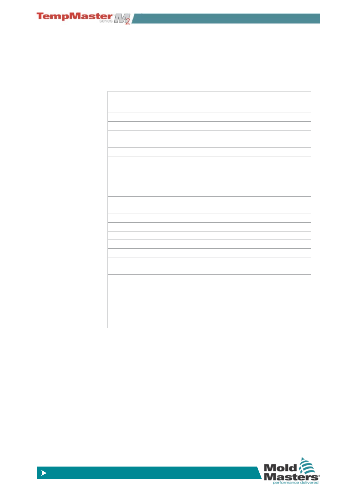
4.1 Specication
The following are general specications. The actual controller/console
supplied may have contractual variations and differ in some specied
options.
Supply Voltage 415Vac 3 phase 50/60Hz with neutral, Other
available include 240/380/400 and 480 volts in
Star or Delta conguration.
Voltage Bandwidth Stable within 20% supply voltage swing
Supply ground-leakage trip 300mA (note: this is for tool protection)
Unit Overload protection Miniature Circuit Breaker
Output overload protection 15A super-quick acting (FF) fuse on both legs
Power output 15A/3600W per zone
Ground Fault Detection 40mA per zone
Thermocouple input Type ‘J’, or type ‘K’
Control Method Self tuning PID
Soft-Start with Auto Tune Unique low voltage method for heater safety
Temperature scale Centigrade (Celsius) or Fahrenheit
Operating Range 0 - 472°C or 32 - 882°F
Control Accuracy +/-1°C
Printer Output Connector USB Port
Data Communications RS-232 serial, DB9 male connector
Communication Protocol SPI, VNC and client over Ethernet
Alarm Output Closing volt-free contacts - 5A max 230V
Remote Input Voltage free pair to signal Boost or Standby
Interface Full colour LCD touch screen (choice of sizes)
Case Details Heavy duty metal cabinet with swing up console
Sizes in mm
M2XS: 310w × 450d × 450h
M2S : 360w × 450d × 800h
M2M: 450w × 540d × 860h
M2L: 450w × 540d × 1330h
OVERVIEW
Filter Option
In countries where noise across power lines is a concern,
Mold-Masters recommends that you t the model 63AYC10B in-line
lter which is supplied by TC Connectivity.
4-1
OVERVIEW
© 2014 Mold-Masters (2007) Limited. All Rights Reserved.
Revised 1 Oct, 2014
www.moldmasters.com
4.2 How to Isolate the Controller
The main Power Switch is sufciently rated to disconnect the total
load current during switch On and switch Off. To prevent its operation,
during maintenance, you can use a suitably-sized padlock, or similar
device, to lock the switch in the Off position.
4.2.1 Switching On
Main Cabinet
Switch ON the Main Isolator to energise the main cabinet.
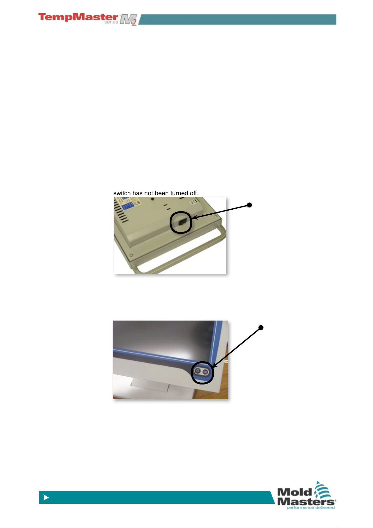
KTS Console
The KTS Console has a main On/Off switch, at the rear right-hand side of the
console case, which is normally left switched “on”.
If left on then the console will start its boot up sequence as the cabinet is
powered up.
If the cabinet is switched on and the console does not start then check this
switch has not been turned off.
Console Switch
TSA2 Console
The TSA2 Console has a non-latching push button at the bottom right hand
side of the screen. After switching on the main cabinet on you then need to
briey press the start button until it illuminates. Release the button and the
console will start its normal boot-up sequence.
Console Switch
4.2.2 Mold Heating
After the consoles have started and the main display screen is visible then the controller may, or may not, start to heat up the zones; it
depends on how the Console Startup option is congured. (on page
5-19.)
If Console startup is set to “Stop” then the tool remains at zero pow-
er and at room temperature. If it set to any of the other three options
(Startup, Standby, or Run) the controller applies power to the zones
so that they heat up.
4-2
OVERVIEW
© 2014 Mold-Masters (2007) Limited. All Rights Reserved.
Revised 1 Oct, 2014
www.moldmasters.com
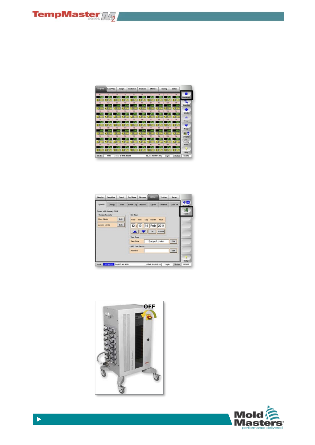
4.3 Switching Off (the Controller)
We recommend that you use the console to shut down the heating
load, and only use the main isolator to switch off a dormant controller.
1. Shut down the heating.
On the Display page, choose [Stop] to reduce the heating to zero.
2. Shut down the Console
On the Utils page, choose [Exit] to shut down the Console Computer.
3. Shut down the Controller
Finally, use the <Main Power Switch> to isolate all the power to the
whole system.
4-3

OVERVIEW
© 2014 Mold-Masters (2007) Limited. All Rights Reserved.
Revised 1 Oct, 2014
www.moldmasters.com
4.4 Screen Layout and Navigation
This page introduces the console to show what functions are available
and what information is given.
Navigation - Top of page
Top tabs to switch between the different pages.
Control - Side of page
Contains various command buttons that change from page to page.
Monitor & Information - Bottom of page
The lower left side shows Run Mode while the centre has messages,
such as prompts when a password is required.
On the right is operator name or admin-level, and lastly the controller
health status.
4-4
OVERVIEW
© 2014 Mold-Masters (2007) Limited. All Rights Reserved.
Revised 1 Oct, 2014
www.moldmasters.com
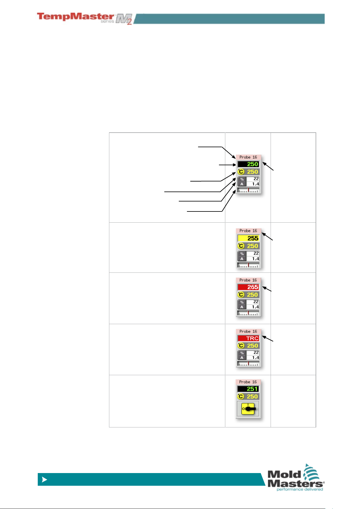
4.5 Display Page
Can be used for
• Monitor – observe zone condition.
• Control – Start/Stop & Boost/Standby immediately available. All
other (“Standby, Shutdown, Stop“) available if you choose [
Mode].
• Set – select any one or more zones to get [
alter zone set-point or run modes.
Monitoring
This Healthy Zone shows:
Zone Name (user congurable)
Actual Temperature (may be Coarse at
whole degree steps or Fine at tenth of a
degree steps)
Scale and Set Temperature
Applied Power (%)
Applied Current (Amps)
Deviation - between Actual
& Set Temperature
Warning Zone
Deviation exceeds 1st stage (Warning)
Set] function to set or
Green text
on Black
background
Black Text
on Yellow
Background
Alarm Zone
Deviation exceeds 2nd stage (Alarm)
Fatal Error
Problem detected. (See
details.)
Zone Off
Individual zone switched off
page 6-37 for
White text
on Red
Background
White text
on Red
Background
4-5
OVERVIEW
© 2014 Mold-Masters (2007) Limited. All Rights Reserved.
Revised 1 Oct, 2014
www.moldmasters.com
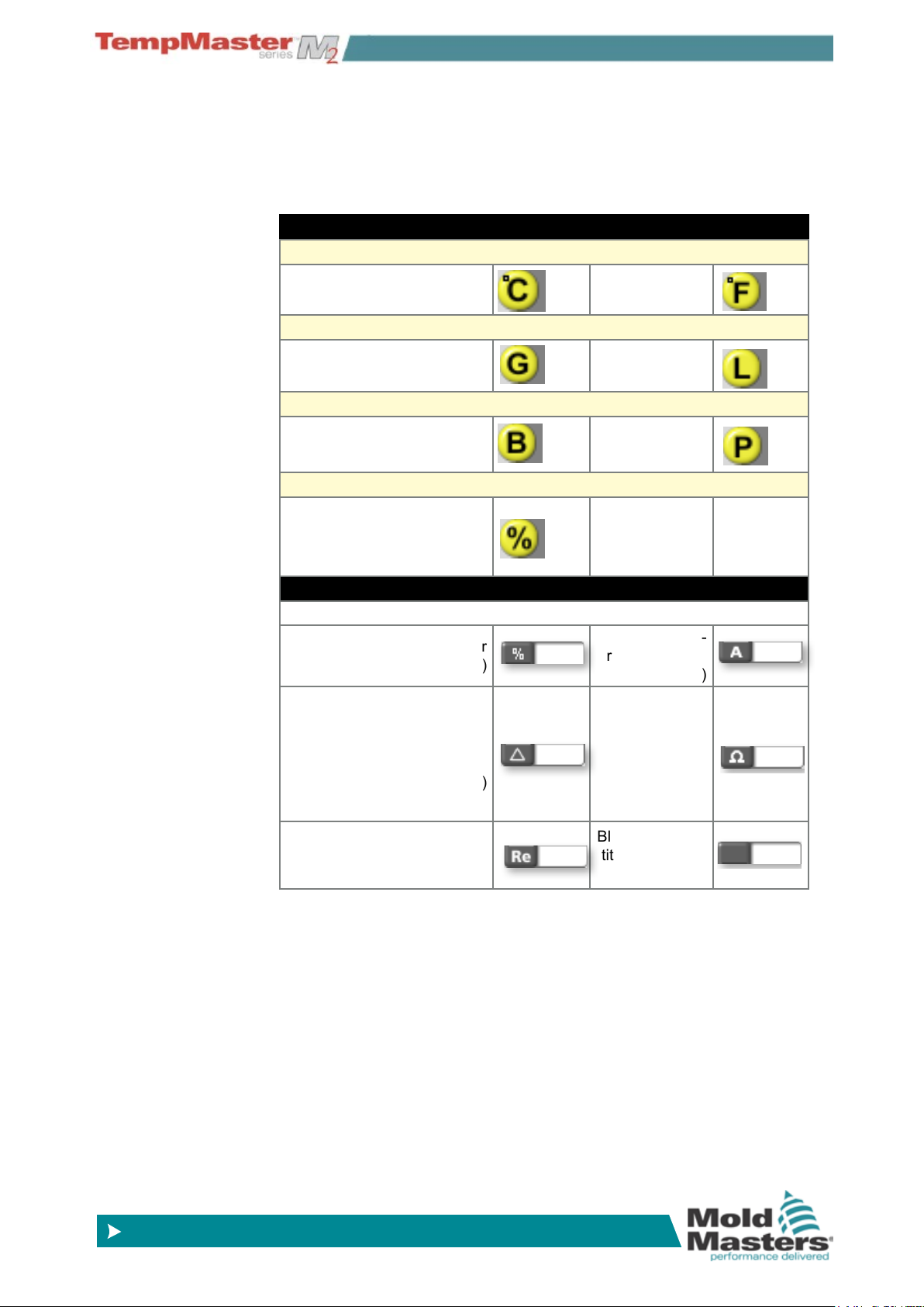
4.6 Display Page – other Symbols and what
they mean
The previous page shows the more common parameters that you
expect to see on a temperature controller – however there are more
values or quantities which are as listed here:
Parameters that are Set
Temperature
Degree C Degree F
Flow (monitoring coolant ow with analogue or digital devices)
Gallons per minute Litre per minute
Pressure (monitoring coolant pressure with analogue devices)
Bar PSI
Other
Percentage (a set percent-
age power output for a zone
with no thermocouple or
closed loop)
Parameters that are Measured (and displayed)
(seen in lower half of panel)
Percentage (power output for
that zone)
Delta (a “difference” symbol
used when comparing ow
or pressure between two
points)
Reynolds Number
(an indication of the quality
of coolant ow in a circuit)
Ampere (Cur-
rent measured
in a zone)
Ohms (Resist-
ance value of
a zone cal-
culated from
stated voltage
and measured
current)
Blank (no quan-
tity currently on
display
4-6
OVERVIEW
© 2014 Mold-Masters (2007) Limited. All Rights Reserved.
Revised 1 Oct, 2014
www.moldmasters.com
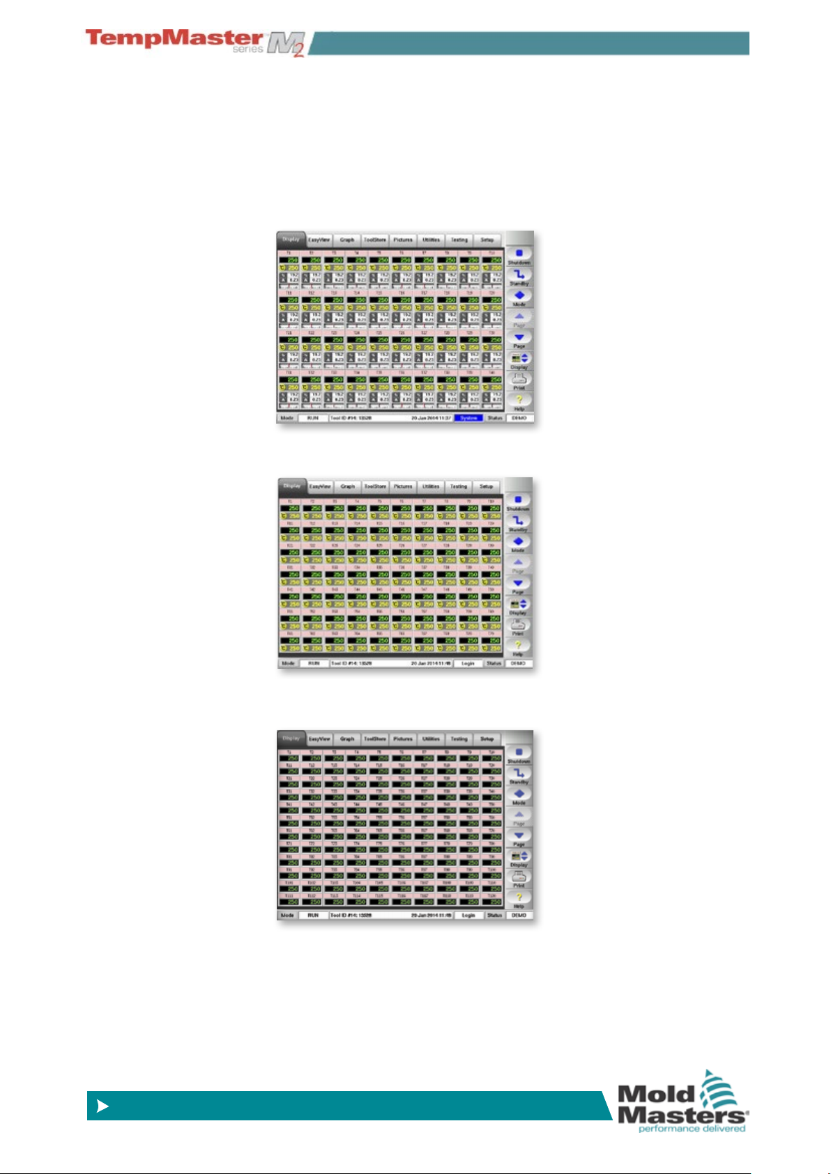
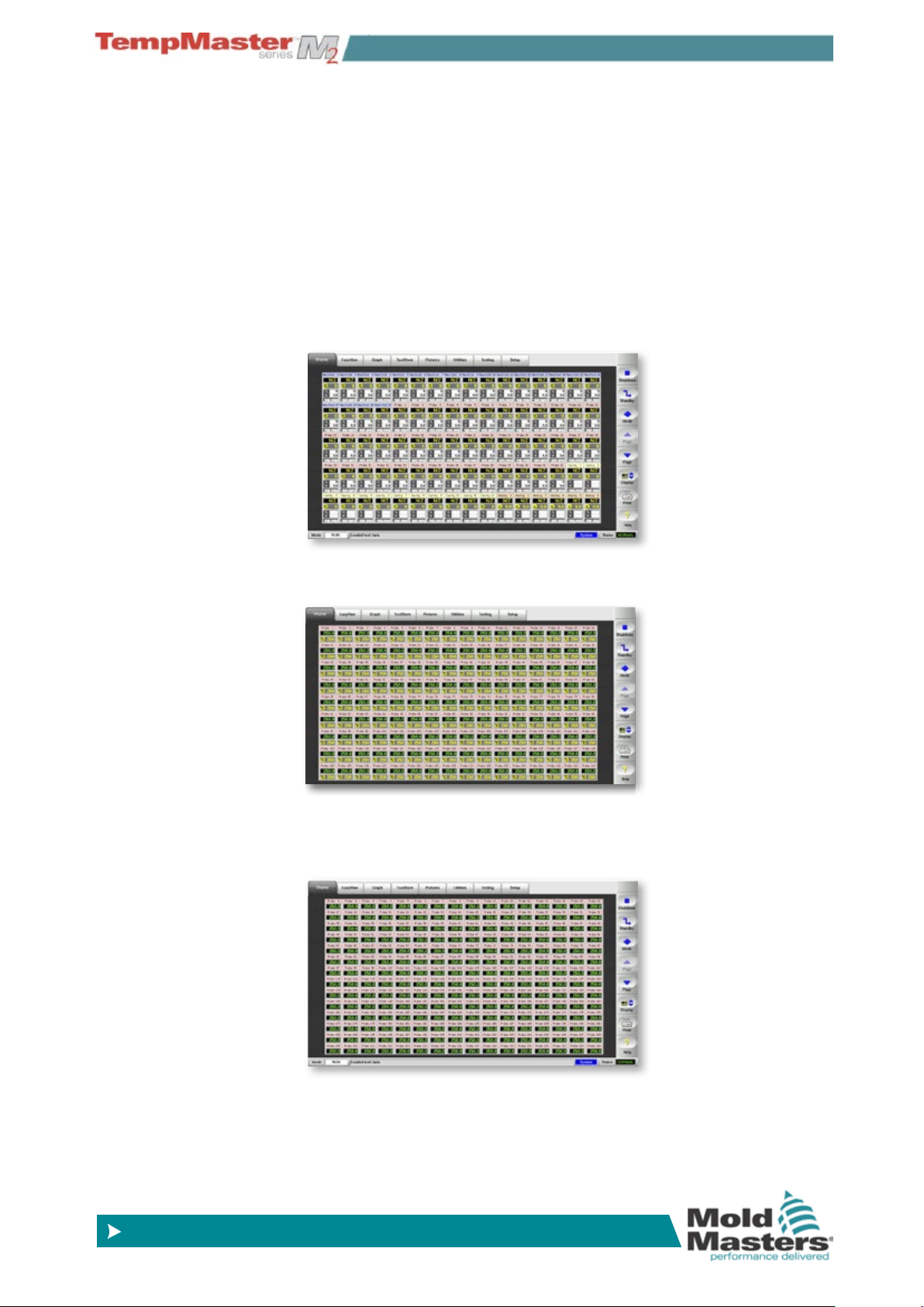
4.7 Display Page – Monitoring (KTS screen)
The basic page shows 40 zones where each zone shows:
Title, Actual, Set, Power, Current and Temperature Deviation.
To view more zones:
1. Use [
Page p] or [Page q] to scroll up and down to see other
zones.
2. Choose [
Display] button to show more zones 70 Zones - each
zone shows Title, Actual and Set .
3. Touch it again to show 110 Zones - each zone shows Title and
Actual.
4-7
OVERVIEW
© 2014 Mold-Masters (2007) Limited. All Rights Reserved.
Revised 1 Oct, 2014
www.moldmasters.com
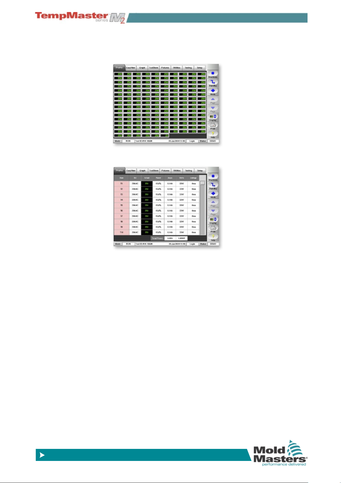
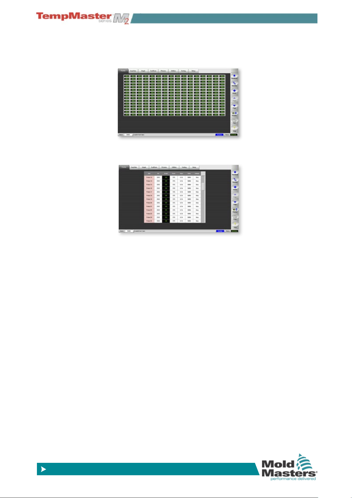
Display Page – Monitoring - contd.
4. Touch it again to show 160 Zones - each zone shows Actual
Temperature.
5. Touch it again to show the Data page which shows the setup and
data for all the console zones.
4-8
OVERVIEW
© 2014 Mold-Masters (2007) Limited. All Rights Reserved.
Revised 1 Oct, 2014
www.moldmasters.com
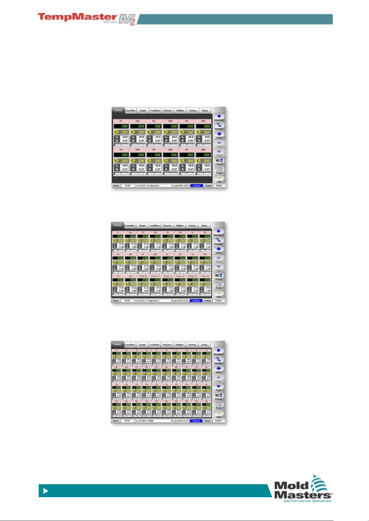
4.8 Display Page – Monitoring (TSA2 wide
screen)
The TSA2 has a wide screen format which offers more zones on the
display page. Other pages appear similar to the standard format KTS
which are used throughout the rest of the manual.
The basic page shows 80 zones where each zone shows:
Title, Actual, Set, Power, Current and Temperature Deviation.
To view more zones:
1. Use [
Page p] or [Page q] to scroll up and down to see other
zones.
2. Choose [
Display] button to show more zones 144 Zones - each
zone shows Title, Actual and Set.
3. Touch it again to show 224 Zones - each zone shows Title and
Actual.
4-9
OVERVIEW
© 2014 Mold-Masters (2007) Limited. All Rights Reserved.
Revised 1 Oct, 2014
www.moldmasters.com
Display Page – Monitoring - contd.
4. Touch it again to show 240 Zones - each zone shows Actual
Temperature.
5. Touch it a last time to show the Data page which shows the setup
and data for all the console zones.
4-10
OVERVIEW
© 2014 Mold-Masters (2007) Limited. All Rights Reserved.
Revised 1 Oct, 2014
www.moldmasters.com
4.9 Display Page – automatic resizing for fewer zones
Both the TSA-Wide and the KTS can resize individual zone panels if
there are not enough zones within the tool to ll the rst page.
4.9.1 Big Panels
12 zones or less in KTS - 30 zones or less in TSA-wide.
4.9.2 Medium Panels
24 zones or less in KTS - 48 zones or less in TSA-Wide.
4.9.3 Normal Panels
40 zones or less in KTS - 80 zones or less in TSA-Wide.
4-11
© 2014 Mold-Masters (2007) Limited. All Rights Reserved.
Revised 1 Oct, 2014
www.moldmasters.com
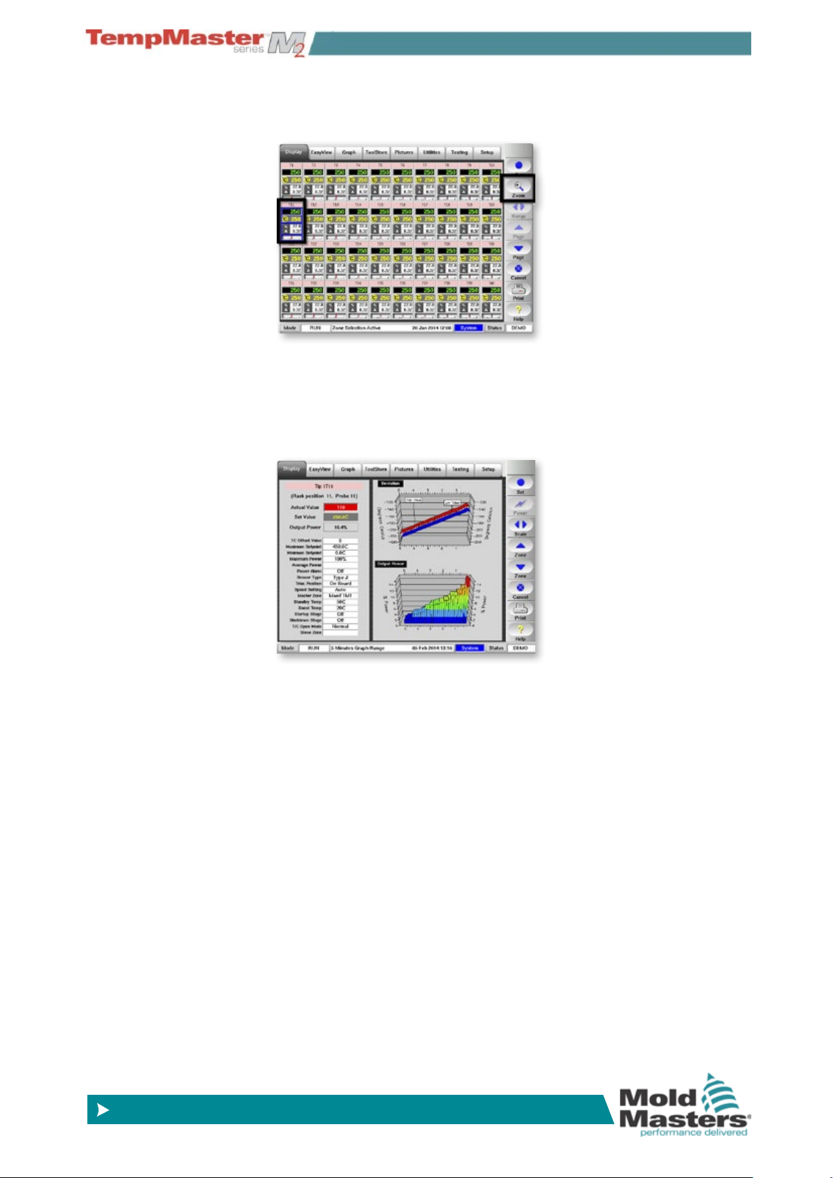
4.10 Display Page – Monitor (Zoom)
1. Touch any zone and choose [Zoom].
2. This opens the Zoom page which shows:
a) Zone Settings.
b) Recent Temperature Deviation.
c) Zone Power Levels (Historical).
OVERVIEW
4-12
OVERVIEW
© 2014 Mold-Masters (2007) Limited. All Rights Reserved.
Revised 1 Oct, 2014
www.moldmasters.com
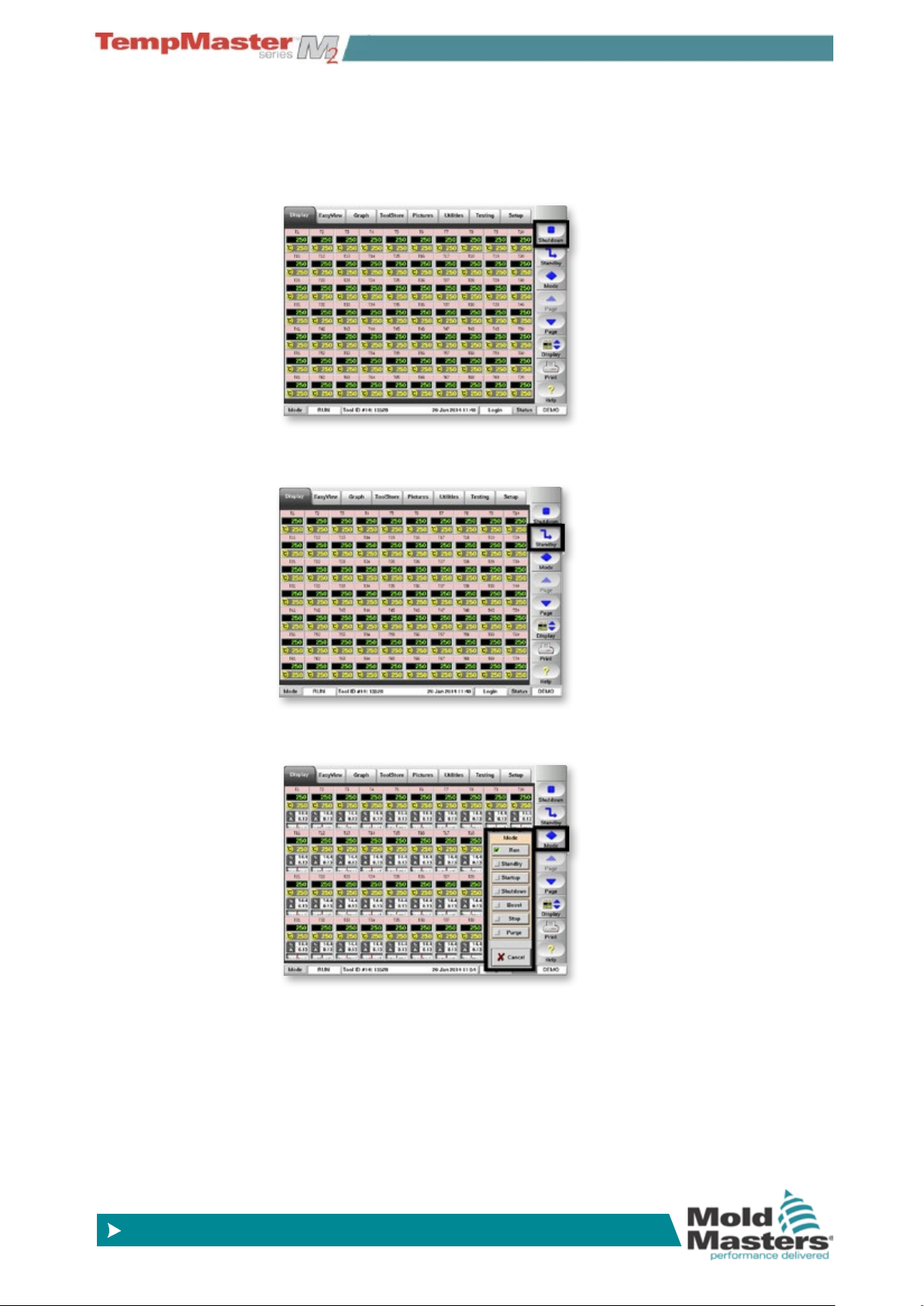
4.11 Display Page – Start, Stop and more
Button 1 - Can appear as [Run/Stop] or [Startup/Shutdown] or
[Sequence/Stop].
Button 2 - Can appear as [Boost] or [Standby].
Button 3 – Mode - Reveals all of the run mode options.
4-13
OVERVIEW
© 2014 Mold-Masters (2007) Limited. All Rights Reserved.
Revised 1 Oct, 2014
www.moldmasters.com
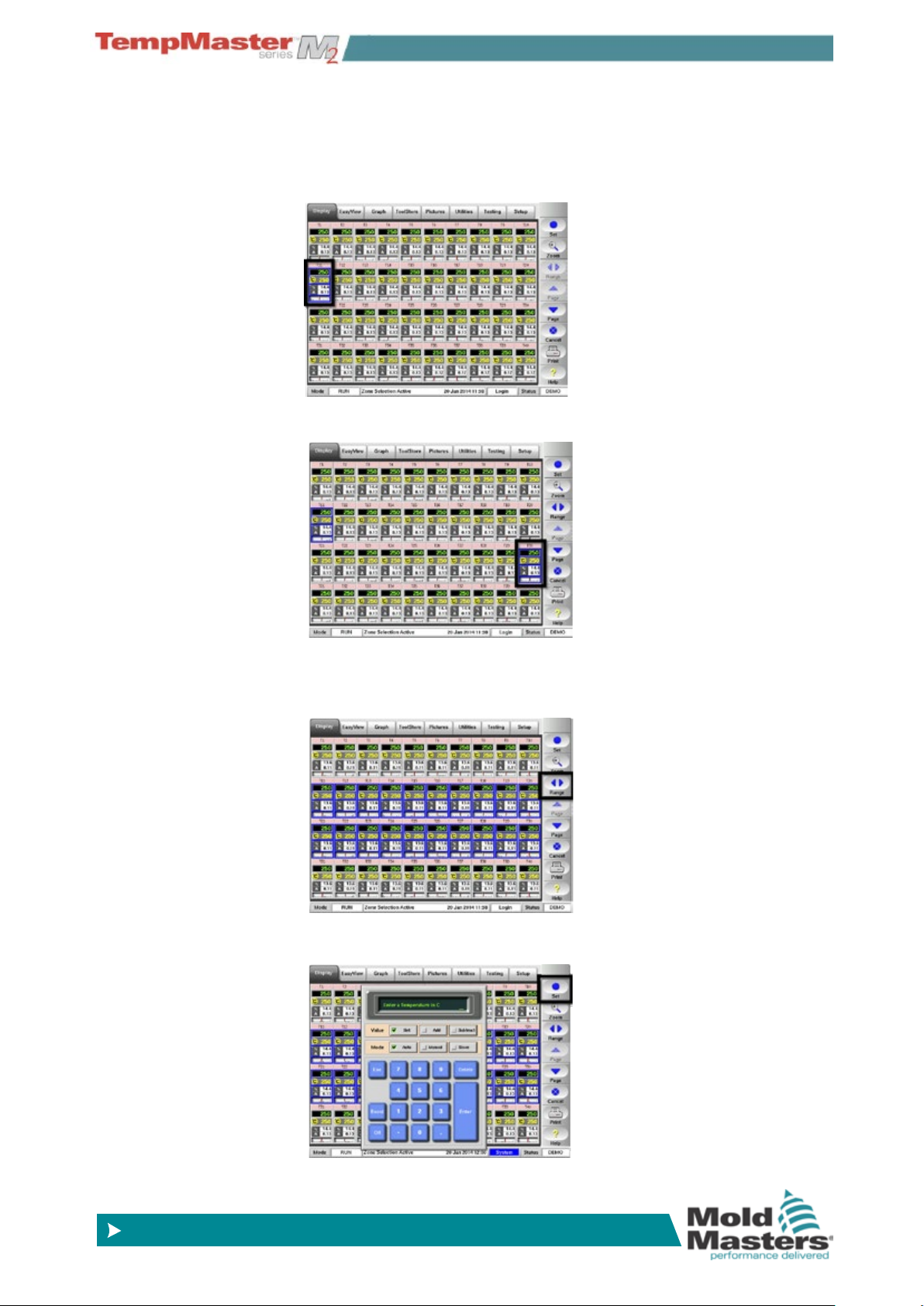
4.12 Display Page – How to set Temperature
The following shows how to set the temperatures of one or more
zones.
1. Choose one zone.
2. Choose another.
3. Choose [
selected.
4. Choose [
Range] to include those zones between rst and last
Set] and, if prompted, enter the User Password.
4-14
OVERVIEW
© 2014 Mold-Masters (2007) Limited. All Rights Reserved.
Revised 1 Oct, 2014
www.moldmasters.com
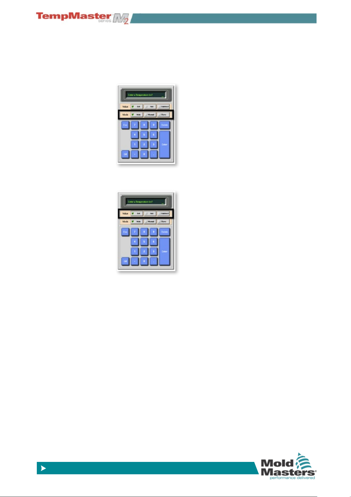
Display Page – How to set Temperature - contd.
5. Choose [Mode] bar to set zone as:
a) Closed (Auto Temperature).
b) Open (Manual Power).
c) or Slave (to another zone).
6. Choose [
Value] bar to Set, Raise or Lower temperatures.
4-15
OVERVIEW
© 2014 Mold-Masters (2007) Limited. All Rights Reserved.
Revised 1 Oct, 2014
www.moldmasters.com
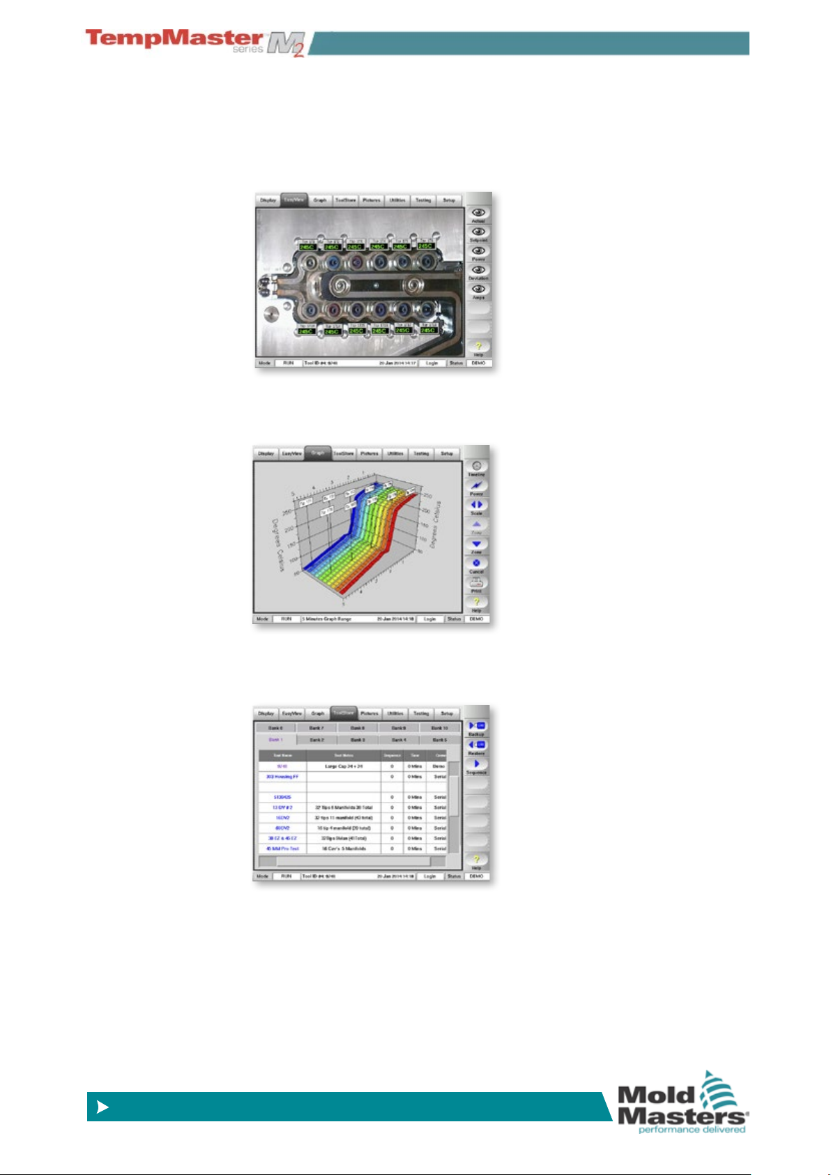
4.13 More Pages
4.13.1 EasyView
Shows zone temperature and their position in the tool. It also shows
Zone Status and can be used to Set zone temperatures.
4.13.2 Graph page
Shows graphs, of temperature versus time, for up to 20 zones at a
time.
4.13.3 The ToolStore page
This is a tool bank in which you can store up to 200 tool congurations.
4-16
OVERVIEW
© 2014 Mold-Masters (2007) Limited. All Rights Reserved.
Revised 1 Oct, 2014
www.moldmasters.com
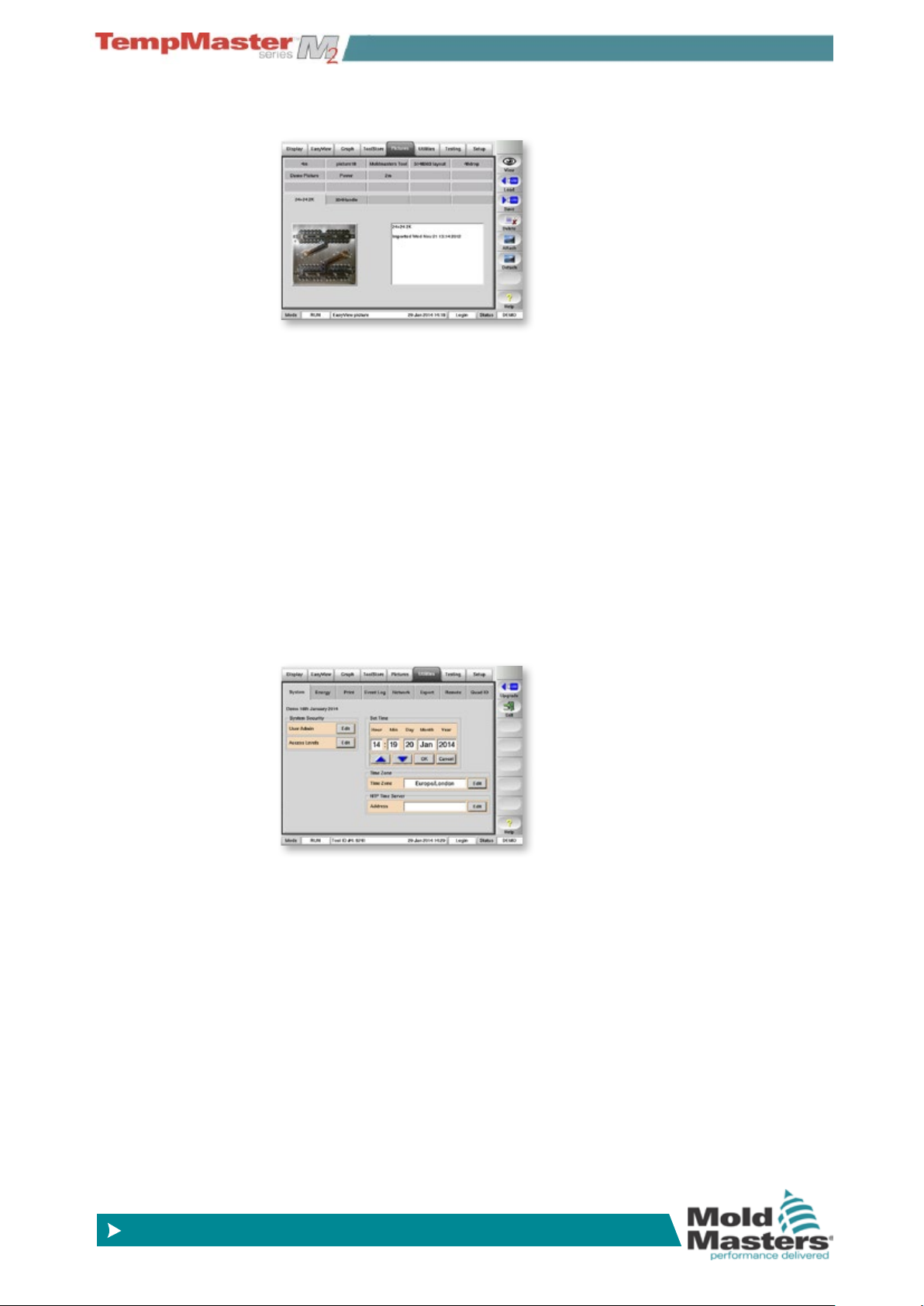
4.13.4 The Picture page
Save, and display, up to 20 drawings or pictures.
4.13.5 The Utilities page
Contains several sub pages:
a) System- change the passwords and the system clock.
b) Energy - display of recent energy consumption over time.
c) Printer - select a driver for your printer.
d) Event Log - to nd changes that have been made to the con-
troller settings.
e) Network - set up the Controller to communicate over a net-
work.
f) Export - obtain historical performance data for any zones over
the last 24 hours.
g) Remote - view any other networked computer via a Virtual Net-
worked Computer (VNC) protocol and set up a remote Master
IP address.
h) Quad IO - set up Quad IO card Inputs and relay outputs.
4-17

OVERVIEW
© 2014 Mold-Masters (2007) Limited. All Rights Reserved.
Revised 1 Oct, 2014
www.moldmasters.com
4.13.6 The Testing page
Check the condition of a mold tool after commissioning or maintenance.
4.13.7 The Setup page
For setting up the system.
4-18

OVERVIEW
© 2014 Mold-Masters (2007) Limited. All Rights Reserved.
Revised 1 Oct, 2014
www.moldmasters.com
4.14 The User Interface
Where the conguration of parameters requires a user interface then
either a keyboard or a keypad is displayed.
Keyboard – this is offered wherever alpha-numeric input is required
such as entering a Password or a Tool Name.
Keypad 1 - Basic numeric.
Keypad 2 - Is an extended keypad which adds:
Value keys – Set, Temp, Add and Subtract to set Temperatures, plus
Mode keys – Auto, Manual and Slave to set working Mode.
Keypads – 3 & 4 - Offers more buttons to select and congure syn-
chro, or spear tips.
Screen Saver
There is an automatic function that dims the screen light by 50% after
5 minutes of user inactivity. Touching the screen anywhere will restore
it to normal level.
4-19

© 2014 Mold-Masters (2007) Limited. All Rights Reserved.
Revised 1 Oct, 2014
www.moldmasters.com
Section 5 - SetUp
New Touch Screen consoles and controllers are provisionally congured at the factory and you may not need this section for a new system.
However, if you need to match a Touch Screen console to a new tool
or environment then you should use this section of the manual and
work through the four main stages which are summarized in section
5.1 and then described in detail through the rest of the Set Up chapter.
What is included in this section
How to create a rst tool
How to congure the control cards
Setting the tool parameters (on the Setup page such as Standby ,
Boost, Alarm Levels, etc.)
Setting the global parameters ( cong vales on the Setup page - Input
Signal, Startup Mode, Console Language, etc.)
Setting the operating parameters (zone temperatures etc. that are set
on the main page)
SETUP
Saving all to a tool bank slot
Setting other Utility page functions (such as Passwords, Printing, etc.)
5-1

SETUP
© 2014 Mold-Masters (2007) Limited. All Rights Reserved.
Revised 1 Oct, 2014
www.moldmasters.com
5.1 Stages included in Setting up a Console
5.1.1 Create a rst tool
This starts at the Tool Page where a [Detect] command interrogates
the cabinet to see what various cards are available and then puts that
information into the Setup page.
5.1.2 Set up Tool parameters
Once the card information has been written into the Setup page you
then need to look at the displayed cards and allocate a duty to those
cards.
It may be that your cabinet is tted throughout with four-zone 15 Amp
cards, but it takes local knowledge to know which zones are nozzles,
which are manifolds or bridges and which are sprue bushes. A screen
that simply reads zones 1-60 is not as instructive as one that reads
nozzles 1-40, manifolds 1-8 etc. Setting your zones to reect the tool not
only makes it easier to use but it will also pre-program control-card characteristics so they are more likely to match the heat load. Even though
automatic rst time start can do this for you it helps if the cards have
some idea of their duty before they are rst used.
Once card duty has been allocated then the various tool parameters
will take up default values – these may be ne for your general use,
but there are many tool parameters (such as warning and alarm levels)
which you may wish to ne tune to your particular tool. You should also
note that they are all congured on a zone-by-zone basis which can al-
low you to make precise settings.
Note also, all the values on the Setup page are stored with the tool
setting which is currently selected on the tool page. If you go to the tool
page and load a new tool for a different purpose then the new tool may
well bring its different setting into this page.
5.1.3 Congure System Settings
The [Cong] button opens more settings such as startup and boost
and tool parameters such as alarms and limits, which are all congured on the Setup page.
5.1.4 Set up Operating Parameters
Once you have all the above set to your particular system you nally
need to go back to the main Display Page and set your main operating temperatures and other values required for any monitoring zones
that you may have in your console for steel temperature, water ow,
coolant temperature or other ancillary facilities.
5-2

© 2014 Mold-Masters (2007) Limited. All Rights Reserved.
Revised 1 Oct, 2014
www.moldmasters.com
5.2 Create a rst tool
1. Select the ToolStore page.
SETUP
2. Select a blank sub-tab and choose [
Detect].
3. Enter System password.
4. Type in a new name for the tool and choose [
Enter].
5. If the tool is connected via a Network to any other cabinet, the next
step presents an option to select the local controller (labelled “Serial Port”) or a remote controller (labelled hrcnetx).
If no network connected controllers are detected, then it automatically passes this option and goes straight on to step 6.
6. The console runs an automatic “Card Detect” routine to nd out
what type and how many cards are tted in the selected controller.
Once it has gathered this information then the console opens the
Setup page for you to start conguring the new tool.
7. If the system has any problem running the detect sequence it may
report an “Auto Detect Failed” and ask if you want to repeat the
Detect routine. If the reason for failure is obvious, such as a loose
network cable, or a mains glitch, during the Detect routine, then
you may choose [
OK] to re-try card detection.
8. If the detection routine continues to fail then contact your supplier
for advice.
5-3

SETUP
© 2014 Mold-Masters (2007) Limited. All Rights Reserved.
Revised 1 Oct, 2014
www.moldmasters.com
5.3 Setup page - cards that may be detected
Cards, initially detected by the New Tool process, are shown in the
second column and will assume their default values. The following is a
list and description of the cards that may be detected by your console:
Card Symbol Description
Z6
Z4
Z2
AI8
D12
WT3
WT4
6-zone card at 5 Amp rating for Probes with
optional Current sensing
4-zone card at 15 Amp rating with current sensing
and optional Ground Fault monitoring
2-zone card at 20 Amp rating for manifolds with
optional Current sensing
8-channel 4-20mA Analogue Input card typically
used with analogue ow sensors to monitor
coolant ow rates.
16-channel digital input card typically used to
accept external signals.
12-channel RTD card used for temperature
monitoring using Resistive Temperature Devices.
12-channel TC card used for temperature
monitoring using thermocouple sensors.
IO3 or 4
IO5
DO32
SVG
4-channel digital Input/Output card for remote
signalling.
4-channel digital Input/Output card for remote
signalling. PLUS remote Tool Selection input
32-channel Digital output Card used to signal
external equipment.
12-channel sequential valve gate card that can
open and close valve gates at discrete pre-set
point.
5-4

SETUP
© 2014 Mold-Masters (2007) Limited. All Rights Reserved.
Revised 1 Oct, 2014
www.moldmasters.com
5.4 Pre-congured Setup values
The table below shows the whole Setup chart and the differing values
that are given to both Probe and manifold zones.
Parameter Probe and
Manifold
Cards
Rack Address slot address slot address slot address
Alias blank blank blank
TC Open Mode Normal blank Normal
Standby & Boost
Temp
Boost Time 0 blank 0
Master Zone blank blank blank
Warn Hi & Lo 5ºC or 9ºF blank 5ºC or 9ºF
Alarm Hi & Lo 25ºC or 45ºF 25ºC or 45ºF 25ºC or 45ºF
Alarm Power Off Off Off
Alarms Active C,B,I C,B,I C,B,I
Alarm Time 10 Secs 10 Secs 10 Secs
Max Set-point
Setting
Min Set-point
Setting
Max Power
Setting
T/C Offset Value 0ºC or 0ºF blank 0ºC or 0ºF
Speed Auto blank Auto
Sensor J-Type blank J-Type
Display Group 1 blank 1
Startup Stage off off off
Shutdown Stage off off off
Reading Avg 0 0 0
Pre-heat These Columns do not appear on
Boost 40%
Delay 5.0 Secs
Time 5.0 Secs
0ºC or 0ºF blank 0ºC or 0ºF
450ºC or 842ºF 450ºC or 842ºF 450ºC or 842ºF
0ºC or 32ºF blank 0ºC or 32ºF
100% blank 100%
the Setup page unless a control
card is congured to be a Synchro/
Tip type
Other
Monitoring
Cards
Synchro/ Spear
20%
5-5

SETUP
© 2014 Mold-Masters (2007) Limited. All Rights Reserved.
Revised 1 Oct, 2014
www.moldmasters.com
5.5 How to Congure the Control Cards
The Setup Grid displays icons in the rst column to show what cards
have been detected.
Because none of the cards know their function, all temperature control
cards initially default to “Probe” zones along with the Probe default
values, as seen in the rst picture.
(Auxiliary cards such as Analogue Input, RTD Cards and other similar
will also default to values suggested in the table on the previous page
“Pre-congured Setup Values”.)
Although the tool may run on this basic setting it is best that you con-
gure any larger, slower zones such as manifolds etc.. Surplus zones
should also be set to “Not Used” this time (for instance, if you have six
cards offering 36 control zones, but only 32 actual zones, it is best to
set the last 4 zones to [
such as T/C Fail).
Such conguration is detailed in the following steps.
1. Choose the rst zone to be re-congured.
Not Used] so they do not display false alarms
2. Choose the last zone to be re-congured.
3. Choose [
4. Choose [
5. Select Zone Type which could be:
• [
• [
• [
• [
• [
Range] to include all those in between.
Set] to see the “Congure Card Slot” menu.
Not Used] to switch off unwanted card zones.
Manifold] to set the zone to a slower response curve which
suits that sized heater.
Spear] if the 4SMODC card is tted. This card has two twin-
channels that are designed to work as a twin Spear-Zone card
with one triac used for the body and the second used for the
tip.
Monitor] to use any control zone from a 6MOD, or similar
card, as a monitor zone only with no control function.
Special] if there are different cards that are not used for
temperature control, for instance:
RTD Zone - suits 12RTD (twelve channel) temperature measuring cards for cooling water.
5-6

SETUP
© 2014 Mold-Masters (2007) Limited. All Rights Reserved.
Revised 1 Oct, 2014
www.moldmasters.com
How to Congure the Control Cards - contd.
IO Zone - suits QCIO (four in/out channels) Input/Output cards.
Water - suits AI8 (8 channel analogue) or 16DLI (16 channel)
water ow measurement cards.
6. Choose any Header colour if the default selection is not required.
7. Choose [
OK].
8. Repeat steps 1 to 7 for other types of zones.
9. The Setup page is now complete with Cards and Zone types and,
as part of this setting up, populated with standard default values.
These Tool Parameters may be accepted or changed. Setting, or
changing, the parameters are described in the following pages.
5-7

© 2014 Mold-Masters (2007) Limited. All Rights Reserved.
Revised 1 Oct, 2014
www.moldmasters.com
5.6 Set the Tool parameters
1. Select the zones.
2. Select the parameter.
SETUP
3. Choose [
Set].
4. Set the Value.
5-8

SETUP
© 2014 Mold-Masters (2007) Limited. All Rights Reserved.
Revised 1 Oct, 2014
www.moldmasters.com
5.7 The Tool Parameters
Function Description Setting Limits
Rack Position Identies the position of the card within
the rack.
Alias Input for alternative zone names. Has an auto-increment number facility.
TC Open Mode Choose a response for any zone that
detects a failed thermocouple.
Normal – No action corrective takenthe zone power sets down to 0% and it
shows a T/C fatal alarm.
Auto Manual - The zone has sufcient
data, after 10 minutes steady running,
to switch to Manual mode at a power
level that should hold the previous
temperature.
Auto Slave – The zone has sufcient
data, after 10 minutes steady running,
to slave the failed zone to another
similar zone.
Nominated Zone Slaving – allows
you to specify a zone to act as a
master to this zone if it were to fail at
any time.
This is not user congurable.
Standby
(temperature)
Boost
(temperature)
Boost Time Set the duration of the “Boost-
Master Zone Select a Master Zone for any groups of
Warning and
Alarm Levels
(Probe or
Manifold)
Warning and
Alarm Levels
(Monitor Zone)
Sets the Standby temperature for any
zone(s).
Sets the Boost value for any zone(s). The maximum Boost value is 250°C or
temperature”.
sub-zones
Set the rst (Warning) and second
(Alarm) stage alarms.
Set the rst (Warning) and second
(Alarm) stage alarms –any
temperatures reaching the higher
Alarm level will generate an automatic
Mould STOP signal (like the Quad IO
TC card).
The maximum Standby temperature is
250°C or 450°F.
450°F above the normal set temperature.
The maximum period for Boost time is
9999 seconds.
Do not select until all zones have been
appropriately congured to Probes and
Manifolds etc..
The maximum Warning or Alarm value is
99°C or 178°F.
The maximum Warning or Alarm value is
99°C or 178°F.
5-9

© 2014 Mold-Masters (2007) Limited. All Rights Reserved.
Revised 1 Oct, 2014
www.moldmasters.com
The Tool Parameters - contd.
Function Description Setting Limits
Alarms Active Offers a selection table which allows
you to decide how any of the following
alarm conditions should affect the
system:
- High Temperature Alarm
- Low Temperature Aarm
- Zone Alarm
- Power Alarm
Options for Alarm actions are:
Console - which displays the alarm
condition in the lower Status Panel.
Beacon - extends the alarm to activate
an attached Alarm Beacon and Sounder.
Mould Protect - puts the console into
Stop Mode. All zone heaters will , as a
result, cool down.
Injection Disable - sends out a shutdown signal from the IO Card which
may be externally congured to stop the
moulding machine.
SETUP
Alarm Time
(seconds)
Maximum Setpoint Setting
Minimum Setpoint Setting
Maximum
Power Setting
T/C Offset
Value
Speed Select, or over-ride, the Auto-
Congure a brief delay between an
alarm condition being detected, and an
external alarm being sent.
Sets the highest permitted set-point for
the zone(s).
Sets the lowest permitted set-point for
the zone(s).
Sets the highest permitted power
level for the zone(s). This will work in
either open loop (Auto) or closed loop
(Manual) conguration. However, it is
not effective for 4MODS cards working
Seki-Spear probes.
Sets a proportional offset between
measured and displayed temperature
to compensate for a probe where the
T/C may not be sufciently close to the
tip.
Speed setting to determine the
control characteristic for the zone
temperature.
The maximum setting for Alarm Time is
999 seconds.
The highest Maximum Set-point
temperature that you can set is 450°C or
850°F.
The lowest Minimum Set-point
temperature that you can set is 0°C or
0°F.
The highest Maximum Power Setting that
you can set is 100% power.
The highest T/C Offset temperature is
±75°C or ±135°F.
Note: The Ultra settings force the
controller to stay in phase angle ring
all the time. These settings are used
where a very small nozzle could show
temperature instability in burst red
mode.
Sensor Select temperature sensor for the
zone(s) (J or K type) for Heater Control
cards or Analogue sensors for AI
cards. Analogue sensors read 0-20 mA
and may be used for ow, pressure or
other device.
5-10

© 2014 Mold-Masters (2007) Limited. All Rights Reserved.
Revised 1 Oct, 2014
www.moldmasters.com
The Tool Parameters - contd.
Function Description Setting Limits
Display Group Select groups of zones to display on
separate Display Pages.
By default all zones are in group 1 but
selected zones can be allocated to
subsequent groups.
Zones that need not be shown on
the Display page can be allocated to
Display Group Zero.
There is a limit of 6 Display Groups.
SETUP
Startup Stage Congure groups of zones into
discrete Startup Groups.
Shutdown
Stage
Readings Avg
(for Analogue
Input Cards)
(The following 4 parameters appear only if a spear card is detected)
Pre-Heat Sets the power level for the spear
Boost Sets the power level required to open
Delay Sets a delay following the signal to
Congure groups of zones into
discrete Shutdown Groups.
Can be used to smooth out analog
input display where the sensor may
send uctuating readings. The drop-
down list is the number of readings
that are read to generate an overall
average.
body.
the tip.
inject until the Boost “opening” power
is applied.
There is a limit of 6 Startup Groups.
There is a limit of 6 Shutdown Groups.
Available setting options are 0, 2, 4, 8, 16
or 32.
NOTE - This parameter only appears if
an Flow Monitor (Analogue Input) card is
detected in the rack.
Time Sets the “Gate-open “period for
applying tip power.
5-11

SETUP
© 2014 Mold-Masters (2007) Limited. All Rights Reserved.
Revised 1 Oct, 2014
www.moldmasters.com
5.8 Congure the Tool & System Settings
1. Choose [Cong] to view the Global/Console parameters.
2. The Congure Controller panel shows two tabs for Tools Settings
and System Settings with a brief description for each.
The Tool Settings are generally concerned with only those parameters which affect the selected tool. To keep the settings or changes made here you must then go to the Tool page and choose
[
Save] to save everything within the ToolStore memory for the
selected tool.
3. System Settings are generally Global parameters and these are
applied to the whole system regardless of what tool has been
selected.
4. You can see an overview for each of the settings if you choose
[
View] in either tab.
5-12

SETUP
© 2014 Mold-Masters (2007) Limited. All Rights Reserved.
Revised 1 Oct, 2014
www.moldmasters.com
5.9 The Tool Settings
The Tool Settings are those parameters which affect only the selected tool. It takes two steps
to save the settings or changes made here. First you must choose [
and then go to the ToolStore page and choose [
Save]. All changes are then saved within the
ToolStore memory for that selected tool.
Function Description Limits
Accept] on this screen
Button One
Mode
Button Two
Mode
Display Mode Set the display page and set-up page to group the
Choose from a range of start and stop options that
can be available on the rst button. Most of the pairing
options are the same start and stop functions that you
can choose fromm the “Mode” options on the Display
Page. They are applicable to any tool that you choose
from the ToolStore.
The “Sequence”, option however is a special start
that relates to a particular tool that must have be set
as a sequence of events or tool settings. More details
aboout Sequence starting can be found in “Sequence
Tools and Settings” on page 6-37.
Choose [
button on the Display.
zones as:
[
Sorted] with all Spear zones displayed rst followed
by Probes, then Manifolds, then Specials.
[Mixed] which groups the probe and manifold zones
as they are positioned within the card rack, (Manifolds
may appear out of sequence order, but grouped with
their corresponding probe zones.)
Standby] or [Boost] as the second mode
If the controller has spear
zones then the Standby
option is greyed out and
the second button option is
xed as [
Boost].
Flow Units Select whether to quantify the Flow Zones in Gallons
or Litres.
Input Timer
(minutes)
If either of the above Stop or Standby options is
initiated then this timer starts as soon as the input
open/close signal is received. Once this timer period
has expired it switches the console into the selected
Stop or Standby mode. If, however, the remote signal
disappears before the Timer expires than it resets the
Timer period to “zero” for a restart.
NOTE - This parameter
only appears if a Flow
Monitor (Analogue Input)
card is detected in the rack.
The maximum period for
Input Timer is 25 minutes.
5-13

© 2014 Mold-Masters (2007) Limited. All Rights Reserved.
Revised 1 Oct, 2014
www.moldmasters.com
The Tool Settings - contd.
Function Description Limits
SETUP
Input Signal
(this comes
from the
HAN4A
auxiliary input
at the rear of
the cabinet)
Power Mode Selects how power levels are shown on the Display
Set how the console responds to a remote input
(normally open pair):
STANDBY If Closed - switches the controller into
Standby mode when the remote input is closed;
and returns to its previous state when the signal is
removed.
STANDBY If Opened - switches the controller into
Standby mode when the remote input is opened;
and returns to its previous state when the signal is
restored.
BOOST if Closed - this switches the controller into
boost mode when the remote line is closed.
STOP if Closed - switches the controller into Stop
mode when the remote line is closed.
STOP if Opened - switches the controller into Stop
mode when the remote line is opened.
Page.
Percentage power is constantly displayed while you
have an option on what is seen in the lower window.
If you have control cards with current measuring coils
this option allows the lower window of each zone to
show three possible parameters.
NOTE:
1. The remote input is only
effective when the system
is in RUN mode.
2. This function defaults to
BOOST when the controller
has Spear zones.
3. Only those zones that
have Boost or Standby
temperatures congured in
their SetUp will respond to
the remote input signal.
Power Alarm
Delay
Pressure
Units
Purge Mode
Quad IO
Reset Time
Choose [
Choose [
been set) to show the power in the zone.
If there are no current measuring coils then the lower
window display will be blank.
Choose [
been set) to show the calculated resistance value for
that zone.
Allows you to pause the Power Alarm by this many
minutes so it does not instantly cause an alarm effect.
Select whether to quantify the Pressure Zones in Bar
or PSI.
Choose [
only) or [Chemical] (to work with special purge
compounds).
This is a timer within the IO Card. The timer will set
all relay outputs to off (de-energised) if it fails to see
communication with the Console within this set time.
The default setting is “0” in which case it will not look
for incoming signals and operate normally.
Amperes] to show the zone current.
Watts] (provided the supply voltage has
Ohms] (provided the supply voltage has
Mechanical] (which uses heat steps
Defaults to Zero minutes
delay.
Maximum Reset time is 90
seconds.
NOTE- This parameter only
appears if an IO card is
detected in the rack.
5-14

© 2014 Mold-Masters (2007) Limited. All Rights Reserved.
Revised 1 Oct, 2014
www.moldmasters.com
Function Description Limits
SETUP
Second
Startup
Stage Soak
Timer
Soak Timer Set a time here to force the console to hold in Soak
Standby
Temp
Select a nal operating mode that the console
assumes once it has completed a Startup Sequence
and attained normal temperature.
[
RUN] is default condition.
[
BOOST] will temporarily assume boost settings until
it times out.
[
STANDBY] will reduce to Standby Temperature
until it is manually or remotely changed.
If Staged Startup is selected then this option allows
you to congure a set time for each stage to hold or
soak before the next stage is initialised.
You may set a different time for each of the stages
that you create.
During Startup, while a Stage is held for its soak
period, then the Mode Window display, at the
bottom of the screen, changes from “STARTUP”
to an message that switches between “SOAK” and
“STAGE1, 2, 3 etc.” until all stages reach working
temperature, when it changes to “RUN”.
mode, at the end of a startup option, before it switches
automatically to Run.
This can be used to insert extra pause, or a period of
temperature balancing, before the console switches to
“run” and sends an Injection Enable signal to the rest
of the machinery.
The Status bar will display SOAK in the Mode box
during this time.
Also a QuadIO output called Soaking has been added
which is active during the Soak time.
Set an overall standby temp which will override
individual standby temperature settings that may be
congured within the earlier Tool parameters.
Leave this set to 0° for individual standby values to
remain valid.
Defaults to zero minutes so
no soak time is introduced
unless selected here.
This option will only be
available if you select
“Stage Startup” as an
option in Startup Mode.
Max standby Temp is
260°C.
5-15

© 2014 Mold-Masters (2007) Limited. All Rights Reserved.
Revised 1 Oct, 2014
www.moldmasters.com
The Tool Settings - contd.
Function Description Limits
Startup Mode Select between three different Startup modes:
MASTER-FOLLOW - a default option that ties the
faster-acting nozzles’ set temperature to slower
manifold’s actual temperature. This produces a
homogeneous rise with all zone temperatures coming
up together.
MASTER-ONLY – heats only the nominated Master
zones rst. It does not apply any power to the
subordinate nozzles until the Master zones have
reached their set temperature.
STAGED – allows you to nominate up to sixteen stage
groups that will heat up in successive stages.
When Staged Startup is selected then the shutdown
automatically follows a staged shutdown. Also when
Staged Startup is selected then a further option “Stage
Soak Timer” allows you to hold stages for a user-
congurable time.
Note, however, that there is a separate allocation for
shutdown groups – so a shutdown pattern need not
be the same as the startup sequence. Also, if Stage
Soak Time has been congured for Startup, it will not
automatically apply during Shut Down.
SETUP
Shutdown
Timer
AUTO-FOLLOW – measures the heat gain of every
zone and automatically holds back the faster (probe)
zones to the same rise rate as the slowest rising zone.
This is very similar to Master-Follow but without the
need to nominate any one Master.
Set a delay period to hold on successive groups
during a Staged Shutdown. It sets, in minutes, the
time that successive zone groups must wait before
each switches off.
Setting this option to zero makes the timer ineffective
so that Staged shutdown is reliable solely on
Shutdown temperature.
The maximum period for
Shutdown Timer is 99
minutes.
5-16

© 2014 Mold-Masters (2007) Limited. All Rights Reserved.
Revised 1 Oct, 2014
www.moldmasters.com
The Tool Settings - contd.
Function Description Limits
SETUP
Shutdown
Temperature
Temperature
Scale
Weight Unit
Sets the temperature to which each Shutdown group
must fall before the next group is switched off.
Raising the shutdown Temperature means that zones
do not have to cool down so much until subsequent
stages are switched off which shortens the overall
shutdown time. Lowering the Shutdown Temperature
has the opposite effect and lengthens the shutdown
time.
Choose [
Choose Metric [
weight.
Degree C] or [Degree F] as required.
Kg] or Imperial [Lbs] as the unit for
Finished changing Tool Settings?
The Shutdown
Temperature setting
defaults to “0” which
represents an extremely
long shutdown interval.
The highest shutdown
temperature permitted
is 260° C or 500°F and
if this set value is equal
to, or higher than, the
normal temperature,
then it has no effect and
the shutdown interval
becomes dependant on the
Shutdown timer.
If you have made any changes to Tool settings note that it takes two steps to save them.
First, you must choose [
choose [
Save].
Accept] on this screen and then go to the ToolStore page and
5-17

SETUP
© 2014 Mold-Masters (2007) Limited. All Rights Reserved.
Revised 1 Oct, 2014
www.moldmasters.com
5.10 The System Settings
These are general settings which apply to the system regardless of what tool may be loaded.
Function Description Limits
Allow Global Set
Allow ToolLoad
Allow Standby
Choose [
manifold zones to be set together, or [Disable] if
they must be set as discreet and separate actions.
Choose [
tools while in Run mode, or [Disable] if you wish to
prevent such changes and force the operator to shut
down to swap tools.
If you choose [
console into Standby Mode from any other operating
mode.
Enable] if you wish to allow probe and
Enable] if you want to be able to change
Enable] then you can switch the
If you choose [
from Stop mode into Standby. Instead you must
rst put the console into a run or start mode before
Standby Mode is available.
Blanking Delay Set how long the screen remains visible. The maximum
Baud Rate Set the communication rate between the Console
and the control cards.
Newer control cards can work at faster speeds
(38400) and units are always matched at the factory.
However if you swap a new card for an older one
you may need to select a lower baud rate (19200
or 9600) to make it work correctly. If the baud rate
is too high for an older card then you will see “N/Z”
because it cannot communicate at that speed.
Calibrate Touch If Enabled this starts a routine to check the alignment
between where you “actually” touch the screen and
where the interface perceives that you touch the
screen.
The process stops the controller so be careful not
to do this while the system is in use. It then places
cross hairs at certain points on the screen – respond
by touching the screen with a ne pointer rather than
a large nger print, and hold it there for 3-4 seconds.
When you remove your pointer, it will reposition the
target for you to touch again. After a few target points
it will nish and recalibrate the screen and re-align its
response to where you touched the screen.
You then need to restart the console.
Disable] then you cannot switch
period for Blanking
Delay is 98 minutes.
You can override
the Blanking Delay
so that it remains
permanently visible
by setting this time
to “99 minutes”.
5-18

© 2014 Mold-Masters (2007) Limited. All Rights Reserved.
Revised 1 Oct, 2014
www.moldmasters.com
The System Settings - contd.
Function Description Limits
Console Startup Select the operating mode that is assumed after
initial Switch On.
This may be Stop, Startup, Standby, Run or
Sequence.
SETUP
Ground Fault Limit
Language You may select a preferred language for the screen
Leakage Mode This offers three modes for Leakage Warning.
Leakage Warn Allows you to set a 1st stage warning for consumed
Leakage Alarm Allows you to set a 2nd stage alarm for consumed
Limit Exceeded
If you choose [
is operative such that the card will reduce output
current and so limit the ground fault current.
If you choose [
to ground. If output is too high then the main output
fuse will rupture.
and online help. It is safe to select a different
language while the system is running. Although the
Console does shutdown and reopen, it does leave
the system running safely during the changeover.
“OFF” - set the Leakage detection off
“Manual” - allows you to set a single absolute
percentage level.
“Auto” - which is the default setting and which will
monitor zone power consumed and warn is excess
power consumption is greater than average.
power on a zone.
This is a percentage level above the average power
level.
power on a zone.
This is a percentage level above the 1st stage
(Leakage Warn) level.
[
Disabled] – means that an attempt to set the
temperature above the limit is non-effective and the
Set temperature stays the same.
Enable] the ground fault detection
Disabled] then fault current can ow
See page 4-41 for
a more detailed
explanation about
Leak Detection.
N/Z Alarm
Power Display Select Power Display as Peak Amps or Derive (a
Slave Address This is where you can input the Slave address for
[
Enabled] – means that an attempt to raise the
Set temperature above the limit will increase the set
temperature to the limit and no more.
Disabled] – leaves N/Z in its normal condition
[
which does not raise a system alarm if it occurs.
[
Enabled] – allows N/Z condition to initiate a
System alarm notication in the lower status Window.
At the same time it energises the Alarm Relay for
remote signalling.
relation between Peak and % power.)
the console when it needs to communicate via an
external protocol.
5-19

© 2014 Mold-Masters (2007) Limited. All Rights Reserved.
Revised 1 Oct, 2014
www.moldmasters.com
The System Settings - contd.
Function Description Limits
Supply Voltage Enter the System Supply Voltage; It is used to
calculate the “Watts” display. This is normally the
phase-neutral voltage on a star supply and the
phase-phase voltage on a delta supply.
Temperature Precision Allows you to set the resolution for the Actual
temperature seen on the Display Page to a oating
point scale which displays temperature to within one
tenth of a degree or an integer scale which rounds
the displayed temperature to the nearest whole
degree. Select [
Float] or [Integer] as appropriate.
Maximum supplied
Voltage is 400V.
SETUP
5-20

© 2014 Mold-Masters (2007) Limited. All Rights Reserved.
Revised 1 Oct, 2014
www.moldmasters.com
5.11 Set Operating Parameters
5.11.1 Selecting zones
1. Choose the First zone.
2. Choose the Last Zone.
SETUP
3. Choose [
Range].
5-21

© 2014 Mold-Masters (2007) Limited. All Rights Reserved.
Revised 1 Oct, 2014
www.moldmasters.com
Set Operating Parameters - contd.
4. Choose [Set].
5. Set the Value.
SETUP
5-22

SETUP
© 2014 Mold-Masters (2007) Limited. All Rights Reserved.
Revised 1 Oct, 2014
www.moldmasters.com
Set Operating Parameters - contd.
5.11.2 To set Probe and Manifold temperatures
1. Choose [Set].
2. Choose [
Auto] .
3. Choose the Temperature Value.
(Choose [
Delete] to undo any last entered gure.)
3. Choose [
Enter] to conrm your settings, or [Esc] to return to the
main page without accepting the new choice and values.
5-23

SETUP
© 2014 Mold-Masters (2007) Limited. All Rights Reserved.
Revised 1 Oct, 2014
www.moldmasters.com
Set Operating Parameters - contd.
5.11.3 To set Spear (Body and Tip) temperatures
1. Start with body temperature - choose [Auto].
2. Set the body temperature.
3. Choose [Synch] for Tip Control.
4. This changes the keyboard for the tip settings.
5. Set the rst value (Pre-heat).
6. Choose [
Enter].
5-24

© 2014 Mold-Masters (2007) Limited. All Rights Reserved.
Revised 1 Oct, 2014
www.moldmasters.com
Set Operating Parameters - contd.
External Signal
7. Set the remaining three values.
(keypad automatically cycles through all four values then clears
after the last value is set.)
SETUP
8. The console view returns to just the Display page.
About the Spear/Tip Cycle Time
The following shows how a spear tip-temperature cycle relates to the
mold cycle.
Trace 1
Mold Cycle
Boost signal
(triggers at rising edge)
Varies in length
Trace 2
Spear Tip
Power
Cycle
Trace 3
Spear Tip
Temperature
Cycle
Boost
Power
Pre-Heat
Power
Gate
open
Gate
closed
Delay
Time
5-25
Boost
Time
Gate-open
period

SETUP
© 2014 Mold-Masters (2007) Limited. All Rights Reserved.
Revised 1 Oct, 2014
www.moldmasters.com
Set Operating Parameters - contd.
5.11.4 To set Cavities, Water Flows and Chillers
1. Select the Cavity zones.
2. Choose [
Set].
3. Set the Values.
4. Choose [Enter] .
5-26

© 2014 Mold-Masters (2007) Limited. All Rights Reserved.
Revised 1 Oct, 2014
www.moldmasters.com
5.12 Save everything to a Tool Bank
1. Select the Tool store page.
2. Select the new tool named earlier on page 5-3.
SETUP
3. Choose [
Save].
5-27

© 2014 Mold-Masters (2007) Limited. All Rights Reserved.
Revised 1 Oct, 2014
www.moldmasters.com
5.13 Set Up EasyView Pages
Step Process More…
1. Prepare
and load an
image.
2. Import the
image.
Select a picture or
drawing of the tool
and save it to a
memory card.
Get the picture
into the picture
page.
Do this on a PC away from the
Console.
See page 6-40 for details.
SETUP
3. Select the
tool.
4. Select the
picture.
5. Attach the
image.
Open ToolStore
and load the appropriate tool.
Open picture page
and select the tab
for the new picture.
There are 20
picture slots and
200 tool slots –
one picture can be
used for more than
one tool.
Choose [
Attach].
5-28

© 2014 Mold-Masters (2007) Limited. All Rights Reserved.
Revised 1 Oct, 2014
www.moldmasters.com
Set EasyView Pages - contd.
Open the picture.
SETUP
6. Congure
the EasyView
Image.
(Choose [
View] or
the picture thumbnail)
Choose [
Choose [
Show].
Place].
Select a zone from
the list.
Touch the picture
to place the minipanel.
Repeat these
steps until you
have placed all the
required zones.
5-29
NOTE:
To move a mini-panel drag it to
another location.
To remove a mini-panel touch
[
Delete] and select zone to
remove.

© 2014 Mold-Masters (2007) Limited. All Rights Reserved.
Revised 1 Oct, 2014
www.moldmasters.com
Set EasyView Pages - contd.
SETUP
6. Congure
the EasyView
Image.
(continued)
Choose [
Exit] to
nish.
Open the
EasyView Page to
see results.
5-30

SETUP
© 2014 Mold-Masters (2007) Limited. All Rights Reserved.
Revised 1 Oct, 2014
www.moldmasters.com
5.14 Passwords and User Access Explained
There are 12 levels of user access which are grouped into three families.
Levels 1-4 - Operator Level
This low-level access is generally restricted to basic operations such
as Start and Stop, Load and Restore tools.
Levels 5-8 - Maintenance Level
This mid-level access gives Operator facilities and adds in further operations such as Set Temperatures, Slave zones, change alarm levels,
change tool settings, congure the set-up page and inspect event log.
Levels 9-12 - Supervisor Level
This high-level access gives access to all functions in steps so that
only Level 12 has complete access to all functions.
Backing up your security settings
These twelve user levels share over 100 different functions. Even with
a factory default restore we would advise that whenever you make any
changes to the default option your next step should be to export those
settings to a USB memory stick. You may need to restore it at a later
date.
5-31

SETUP
© 2014 Mold-Masters (2007) Limited. All Rights Reserved.
Revised 1 Oct, 2014
www.moldmasters.com
Passwords and User Access - contd.
5.14.1 Set up User access
To access and set up User accounts and user access rights ensure
you are already logged in at an administrative level. Initially this is
“System” user.
1. Choose [Login].
2. Give “system” Password .
5-32

SETUP
© 2014 Mold-Masters (2007) Limited. All Rights Reserved.
Revised 1 Oct, 2014
www.moldmasters.com
Passwords and User Access - contd.
3. See Login conrmed.
When you are logged in as high-level user then you have a choice
of setting up [User Admin] to determine who can do what.
4. Or select [Access Levels] to alter available functions for the pre-
dened groups.
5. Users who attempt to use this function without security clearance
will be barred from entering these options.
5-33

SETUP
© 2014 Mold-Masters (2007) Limited. All Rights Reserved.
Revised 1 Oct, 2014
www.moldmasters.com
Passwords and User Access - contd.
5.14.2 Congure users
User admin function gives control over permitted users who can be
individually named each with unique passwords.
Password must be at most sixteen characters in length and may contain any characters presented on the keyboard.
To add a new user choose the [
Add user] icon.
This opens a new User panel where you can provide:
• User Name (rst, middle and last).
Note: the Login window will display the user name by showing
the rst and middle name initials, followed by all of the last name.
It has room to display names of 10-12 characters - so any name
longer than that will not all be seen.
• Their security level from 1-12.
• Their unique password which can be between 1 and 16 characters
in length. Any character available on the keyboard is permissible.
5-34

© 2014 Mold-Masters (2007) Limited. All Rights Reserved.
Revised 1 Oct, 2014
www.moldmasters.com
Passwords and User Access - contd.
5.14.3 List current users
To review your current listed users choose the [User List] icon.
This displays a scrollable list.
SETUP
To review a user’s details choose the [
To delete a user choose the [
Note that although a deleted user may no longer be operable or visible, that
user’s records will be maintained in the data les to lookup past events.
Delete User] icon.
User Edit] icon.
5-35

© 2014 Mold-Masters (2007) Limited. All Rights Reserved.
Revised 1 Oct, 2014
www.moldmasters.com
Passwords and User Access - contd.
5.14.4 User Admin options
Other User access facilities are detailed here:
SETUP
Choose [
Settings].
This opens the options panel.
Auto Login User - allows you to change the Console so it starts with
a named user logged in automatically without the need of a password.
In most occasions this is left [
Off] so that you need to login at some
level to make any change - almost essential in a large factory.
Alternatively you could choose [
System] to allow full unrestricted use
- probably an easy option for a single user situation.
Or anything else in between these two extremes.
The Login Mode can permit login with just a [
step login requiring [
User ID] plus the associated password.
Password] or as a two-
Login time allows you to set how long a login will remain effective
while it is idle - this is in minutes.
Export and Import user lists give you a simple means to move user
lists from one console to another via a USB Memory stick.
5-36

SETUP
© 2014 Mold-Masters (2007) Limited. All Rights Reserved.
Revised 1 Oct, 2014
www.moldmasters.com
Passwords and User Access - contd.
5.14.5 Congure user limitations
As you scroll through the Access Levels you nd many functions that
are restricted according to their job title.
(Note: The job Title “Operator 1”, Operator 2” etc. are not user den-
able so you cannot create unique role titles.)
To add in any extra function, nd the point where your chosen function
meets with your chosen user level. Touch the screen at that blank box
to add that function against that level of user.
For instance , touching [
Enter Boost Mode] at Operator 1 enables
that function to the selected operator level..
The logic assumes that any function added to a lower level user will
be OK for all those who are higher ranking.
However, if this is more than you need you can deselect that function
from some columns.
Touch in any box where you wish to remove a function permission.
5-37

SETUP
© 2014 Mold-Masters (2007) Limited. All Rights Reserved.
Revised 1 Oct, 2014
www.moldmasters.com
Set Up - More Features
5.15 Melt Leakage Detection
An automatic Leakage Detection System is available on the console
and it is set to Auto by default.
It monitors zone power levels to check that there are no undue changes over any period of time. If a melt leak appears at any point then the
corresponding zones start to consume abnormal amounts of power. If
this call for extra power is seen over an extended time (by default 20
minutes) then it is assumed there is most likely some melt leak and
alarms are raised, and they can initiate a number of different events.
Leakage detect function has three options which are:
“Auto” - this is the default condition which gives you a warning at rst
stage and an Alarm condition at second stage. Both stages are auto-
matically calculated from the user-denable percent values.
“Manual” - you may choose to have a single power percent level
above which an alarm condition exists.
“Off” - the leakage detection and alarm outputs can be turned Off by
selecting this option.
5.15.1 Conguring Auto Leakage Detection
Once leakage detection is set to “Auto” then only two further parameters are required.
The rst stage or “Warn” level defaults to 10% above normal average
power while the second stage “Alarm” level defaults to 20% above the
1st stage setting. Both settings are user congurable.
If conditions are such that you want instant action and no “Warn” then
Set the “Warn” setting to 99% and the Alarm at the required percentage level. Similarly if you want “Warn only and no “Alarm” then set the
unwanted Alarm level to 99” so it is ignored.
Both of these values are set up within the System parameters, which
are accessed on the Setup page after choosing [
Cong].
Note that average power is an accumulated gure. It takes about 5
minutes of settled running until a steady average power is reached,
after which, it will sample actual power levels for the next 20 minutes
to get a realistic algorithm to use as average power. During all this
time the message in the Alarm Power column shows “sampling”.
5-38

SETUP
© 2014 Mold-Masters (2007) Limited. All Rights Reserved.
Revised 1 Oct, 2014
www.moldmasters.com
Conguring Auto Leakage action
As leakage detection is set to Auto by default then when any zone Power level raises
enough to trigger a 2nd stage Alarm it activates Console Alarm with Beacon and sends
an Injection Disable output.
These can be set in the Alarms Active column
on the Setup page which opens an Alarm box
as shown here.
Auto Leak Display
The settings for Auto Leak appear is several places.
Display “data” page - shows two new columns “Average Power”
which shows the current average power being consumed, where as
Alarm Power shows “Sampling” during the initial checking time, after
which it shows the calculated gures for 1st and 2nd stage alarms.
Display Zoom page - also shows “calculating” initially then shows
gures for 1st and 2nd stage alarms.
Setup page - has a new column that shows “Auto” within the “Alarm
Power” column.
Setup page - when you select “Alarms Active” there is a small matrix
to set what conditions trigger what events. Within this matrix, Alarm
Power (which is the leakage detect parameter) may be set to initiate
any or all of the Console, Beacon, Mold Protect and Injection Disable
alarms.
Leakage detection events can always be seen in the Zone Windows
on the Display page. The % box normally displays in green when
reading are normal or healthy but changes to Amber if the measured
power exceeds 1st stage level and shows in Red if it exceeds the 2nd
stage level.
Any other displays such as the Status window and the alarm beacon
are dependant on the settings in Alarm Active as described immediately above.
Temporary disabling
Leakage monitoring and average power calculations are disabled
while the system is in Standby or Boost mode. However the average
calculation is not lost, but stored, and it all reverts to average monitoring when the system returns to normal mode.
If any zone temperatures are changed or if the console is stopped
then all average power calculations are reset. In each case there will
be a delay unitil new avarage power levels are recalibrated and the
Leakage detection function is restored.
5-39

SETUP
© 2014 Mold-Masters (2007) Limited. All Rights Reserved.
Revised 1 Oct, 2014
www.moldmasters.com
5.16 Set Time and Date
We recommend that you set the correct time and time zone so that
you may take full advantage of the software features that use the time
function.
1. Enter the Set time area by touching the System tab.
2. In the Set Time box, touch the time element that you wish to
change.
3. Use the [p] and [q] buttons to set the required value.
4. Choose [
5. Use [
OK] to save the new setting to the system.
Time Zone] to set your own Time Zone description if you
choose.
6. Use [
NTP Time Server] to synchronise many controllers to the
same time by inputting the local NTP Time Server address.
5-40

SETUP
© 2014 Mold-Masters (2007) Limited. All Rights Reserved.
Revised 1 Oct, 2014
www.moldmasters.com
5.17 Utilities - Energy Page
Within the Utilities section is a live energy monitoring page that reports
energy and material consumption. Choose [
od viewed from 5 or 30 minutes to a full 24 hours.
The energy statistics are derived from:
• parameters that you can manually input and,
• from the actual current that the control cards measure.
Scale] to change the peri-
Choose [
Cong] to open the Energy Settings panel. This has param-
eters for Part weight and Cycle time which will display material used
every hour.
The console calculates the Kilowatt gures from a product of actual
measured current against the stated supply voltage which you can set
in System Settings in the Setup-Congure options.
5-41

SETUP
© 2014 Mold-Masters (2007) Limited. All Rights Reserved.
Revised 1 Oct, 2014
www.moldmasters.com
5.18 Print Page
5.18.1 Using a locally connected Printer
1. Use the Printers list to select the printer that you intend to use. If a
precise match is not available then select something similar since
most similar printers share drivers.
2. Choose Connection [
(The Local/Remote option is not available on the TS console.)
3. Choose standard European [
4. Choose [
Accept] to conrm your printer selection.
Edit] and select the Local USB option.
A4] or American [Letter] size.
5.18.2 Using a remote Network Printer
1. Use the Printers list to select the printer that you intend to use.
2. Choose Connection [
network:
Network TCP (Transmission Control Protocol) a Standard Network communication protocol.
Network LPD (Line Printer Daemon) for a UNIX/Linux Network
Protocol.
Windows SMB (Server Message Block) a communication protocol favoured by Windows networks.
3. Choose Printer Address [
address for a known network printer. Alternatively, supply a resource name if your system uses a name server.
Edit] and select a network descriptor for your
Edit] button and key in the Local Area
4. If your network uses the Windows SMB option then you must provide a printer name - choose the Share Name [
key in the printer name which identies the remote network printer.
5. Choose standard European [
6. Choose [
Should you have any difculties then contact your own IT department
for help with LAN printer conguration.
Accept] to conrm your printer selection.
A4] or American [Letter] size.
Edit] button and
5.18.3 Printing to a USB Memory Stick
Another option in “Connection” is [Print to le] which allows you to
print out a le, in either a raster or pdf format, to a USB Memory Stick.
1. Choose Connection [
Note that the “Make” option greys out and the “Model” option
changes to “File”.
2. Choose File [
3. Use the USB port and a USB Memory Stick as a transfer media
for making prints from any other pages. (“Print to le” on page
7-3 for details.)
Edit] and then choose [JPEG], [PNG] or [PDF].
Edit] button and choose [Print to le].
5-42

SETUP
© 2014 Mold-Masters (2007) Limited. All Rights Reserved.
Revised 1 Oct, 2014
www.moldmasters.com
5.19 Event Log and Export Pages
Event Log is used to store and retrieve recent events and is explained
more fully on page 6-16.
Export is used to collate running data and is explained more fully on
page 7-5.
Remote and Quad IO pages
These two pages may be used to connect your controller into a wider
system that allows remote interfacing.
They should only be congured by competent IT staff who are familiar
with networking protocol or machine interface.
Utilities > Remote page.
Utilties > IO Page.
Should you need further information please contact your supplier.
5-43

© 2014 Mold-Masters (2007) Limited. All Rights Reserved.
Revised 1 Oct, 2014
www.moldmasters.com
Section 6 - Operation
This section of the manual is divided into several main areas that
include:
• the basic Starting and Stopping along with Boost and Pause controls.
• changing temperature settings while the controller is running.
• inspecting historical graphs and event logs to trace back how the
controller has behaved over the last 5 or 30 minutes, or even the
last 24 hours.
• recognising what alarms may be generated, what they mean and
what to do about them.
• using the toolstore and other facilities to adapt quickly to different
circumstances.
What is included in this section
OPERATION
Logging in and out
Control Zones – Start, Stop and more
Use the Display Page to control and monitor temperatures
Use the Easy-View page to control and monitor temperatures
Use the Purge Option
Looking at temperature history for the last 5 to 30 minutes
Looking at temperature history for the last 24 hours
Check the log book for past events
Alarms - what alarms may be seen on the controller.
Using the ToolStore Page
Creating a new Tool
Renaming an Existing Tool
Loading Tool settings (Locally & Remotely)
Saving Tool settings
Deleting a Tool
Backing-up Tool Settings
Restoring tool settings
The Picture Page
The Quad I/O Card
6-1

OPERATION
© 2014 Mold-Masters (2007) Limited. All Rights Reserved.
Revised 1 Oct, 2014
www.moldmasters.com
6.1 Log in
You can log in from any page by touching the [Login] button on
the bottom Status and Mode bar.
This then shows a keyboard in which you must type your pass-
word. If the password is accepted then the screen conrms “User
Logged In”.
Once logged in then you can access operations until either the
logout timer expires or you log out.
Also if you try to make any changes while not logged in, then the
login keyboard appears to request a valid password. Once you
enter that then you are logged in to continue the action.
6.1.1 Log Out
Logout is achieved automatically by inputting no further commands for the Logout time setting. Once the screen has been idle
for that time then the current user is logged out.
Alternatively you can immediately log out if you touch the same
[
Login] button after which the console asks you to conrm the
logout action or cancel if it was an erroneous touch.
6-2

© 2014 Mold-Masters (2007) Limited. All Rights Reserved.
Revised 1 Oct, 2014
www.moldmasters.com
6.2 Control Modes for all zones
(from the Display Page)
Operation Available byDescription
OPERATION
RUN
STOP
STANDBY
STARTUP
Button One
or Mode
Button
Button Two
or Mode
Button
Button One
or Mode
Button
Button One
or Mode
Button
Switches on all zones.
Switches off all zones.
NOTE: Selecting Stop does not remove voltage
from the heaters; it switches off by setting all
the target temperatures to Zero. Do NOT try to
change fuses or disconnect units while in this
mode.
Reduces the temperature of all zones that have
any Standby Temperature congured on the
Setup page.
Temperature remains reduced until RUN
command is given.
STARTUP
Initiates a starting sequence that is congured
on the Setup page.
MASTER-FOLLOW – Applies power to Master
zones then adjusts other zones’ Set Temp to
follow Master Zones’ Actual Temperature –
produces a homogeneous heat rise.
MASTER-ONLY – applies power to Master
Zones but waits until they are at full
temperature before switching on all others.
STAGED – applies power to nominated stage
zones and then waits until they reach normal
temperature before switching on next stage
zones. This cascades the startup sequence
through several stages.
SECOND STARTUP
When all the zones have reached their set
temperatures the system then goes into
SECOND STARTUP mode which may be
congured to either:
RUN – maintain their Set Temperature.
BOOST – temporarily raise the temperature
and then settle back to normal Set
Temperature.
STANDBY – lower zone temperatures until Run
command is given.
6-3

© 2014 Mold-Masters (2007) Limited. All Rights Reserved.
Revised 1 Oct, 2014
www.moldmasters.com
Control Modes for all zones - contd.
Operation Available byDescription
OPERATION
SHUTDOWN
BOOST
PURGE
Button One
or Mode
Button
Button One
or Mode
Button
Mode
Button
Initiates a switch-off sequence that is
determined by the startup mode.
With the Startup Mode set to Master-Follow or
Master-Only:
Shutdown switches off the nominated
master zones then adjusts all other zones’
Set temperatures to the manifold Actual
temperatures. The whole tool then cools in a
homogeneous manner.
With the Startup Mode set to Staged:
Shutdown consecutively switches off the zone
groups in timed intervals and in the order as
nominated by Shutdown Stage conguration.
When the Shutdown sequence nishes then
the system goes to STOP mode.
Temporarily raise the temperature of all zones
that have any Boost Temperature congured on
the Setup page.
When the boost period expires then zone
temperatures return to normal Set levels.
This is a pre-set Purge sequence to help you
change color in the mold tool. (For details about
this option read “Using The Purge Sequence”
on page 6-12.)
6.2.1 Control for individually selected zones
Operation Available by Description
1. Select Zone.
STOP
BOOST
2. Choose [
3. On keypad,
choose [
1. Select Zone.
2. Choose [
3. On keypad,
choose [
Set].
OFF].
Set].
BOOST].
Switches off the
one zone.
Temporarily
raises the
temperature of
the selected
zones until
Boost Time
expires.
6-4

OPERATION
© 2014 Mold-Masters (2007) Limited. All Rights Reserved.
Revised 1 Oct, 2014
www.moldmasters.com
6.3 More about using Boost
• Boost mode is determined by two quantities that determine boost –
the boost temperature and it’s time.
• Boost Time that takes precedence over boost temperature. Once
the boost period expires then the extra heating power is removed
regardless of whether the zones actually reach the congured
Boost temperature.
• Boost raises the temperatures of only zones that have any boost
temperature congured.
• Boost mode is only available while the system is in Run mode.
• The Boost Command may be received locally through the console
interface or remotely via the remote console interface or the Quad
I/O Card.
Manual Boost display
When a Manual Boost command is given, the Mode window shows
“BOOST” in black letters on a yellow background. The BOOST message displays until Boost-Time period expires after which the zones
returns to normal set temperature and the Mode Window shows RUN.
Remote Boost display
When a boost Command is received from an external source the
Mode window shows M/C BOOST as black letters on a white background. The time that the message displays for is dependent on the
external signal.
Brief Signal - If the external signal is brief for example, it lasts 1
second, and the Boost Time is set to something longer, perhaps 3
seconds, then the nozzles are boosted for 3 seconds after which they
return to normal level. The M/C BOOST signal is also displayed for 3
seconds after which it returns to RUN.
Long Signal - If the Boost Time is set to 3 seconds and the external
signal lasts for 4 seconds, then the nozzles are boosted for 3 seconds
and then return to their nominal value. However the M/C BOOST message in the Mode window displays for 4 seconds (while the external
signal is present) even though no boost current is being applied for the
last second.
6-5

© 2014 Mold-Masters (2007) Limited. All Rights Reserved.
Revised 1 Oct, 2014
www.moldmasters.com
6.4 Use Display Page to change
Temperatures
1. Select the desired zones.
OPERATION
2. Choose [
3. And then:
a) To Set a new temperature, choose [
b) To Raise the overall temperature, choose [
c) To Lower the overall temperature, choose [
Set] to display the keyboard.
Set].
Add].
Subtract].
4. Enter the Temperature setting or change.
5. Choose [
Enter] to make the setting or [Esc] to defer the action.
6-6

OPERATION
© 2014 Mold-Masters (2007) Limited. All Rights Reserved.
Revised 1 Oct, 2014
www.moldmasters.com
6.5 Use the Display page to change Modes
1. Select the desired zones, this automatically changes the function
keys from Global to Zone.
2. Choose [
Set] to display the keyboard.
3. Choose the working mode which may be Manual (open loop
working) Auto (closed lop working), or slaved to a different zone.
4. Finally type in the value:
a) for Manual, enter the Percentage power.
b) For Slaving, select a similar master zone from the Zone list.
c) For Auto, enter the required zone temperature.
5. Choose [
Enter] to make the setting or [Esc] to defer the action.
6-7

OPERATION
© 2014 Mold-Masters (2007) Limited. All Rights Reserved.
Revised 1 Oct, 2014
www.moldmasters.com
6.6 More about Slaving Zones
There are several points that you should remember when using zone
slaving.
1. You can only slave like zones for like zones. - You cannot slave
a probe zone to a manifold zone.
2. You cannot nominate another zone that is already slaved to
another. - If, for example, zone 2 is currently slaved to zone 3,
you cannot slave zone 1 to zone 2. The leading zone must already
be a healthy zone.
3. You cannot nominate a zone that creates a loop. - If, for example, zone 2 is slaved to zone 3, then you cannot slave zone 3
back to zone 2.
4. When selecting a lead zone to slave to you should nd a similar zone type that is currently operating at the same temperature and at the same power level. - If you nominate a lead zone
that is working at the same temperature but outputting a noticeably different power level then the slaved zone may not regulate
efciently.
6-8

OPERATION
© 2014 Mold-Masters (2007) Limited. All Rights Reserved.
Revised 1 Oct, 2014
www.moldmasters.com
6.7 About EasyView page
The EasyView page allows you to relate zone temperatures to physical position.
Apart from the zone (alias) name, the mini-panels show one other
piece of information which may be either:
• the Actual temperature,
• the Set-point temperature,
• the current Applied power,
• the deviation between Set and Actual temperatures
• the current (or Amps) consumed by that zone
While no zone is selected, you can change the displayed value by
choosing one of the [
[
Amps] buttons at the side of the page.
Actual], [Set-point], [Power], [Deviation] or
Choose any one mini-panel within the EasyView page to make the
sidebar function buttons switch to [
Set] and [Zoom] ready for your
next input.
The mini-panel header is not color-coded as on the Display page.
However the lower half, while showing temperature or power is
color-coded to indicate the alarm status, as shown below.
Green on Black Normal working
Black on Yellow 1st stage Warning status
White on Red 2nd stage Alarm Status or Fatal Error
6-9

OPERATION
© 2014 Mold-Masters (2007) Limited. All Rights Reserved.
Revised 1 Oct, 2014
www.moldmasters.com
6.8 Use EasyView to change temperatures
1. Select the desired zones.
2. Choose [
Set] to display the keyboard.
3. And then:
a) To Set a new temperature, choose [
b) To Raise the overall temperature, choose [
c) To Lower the overall temperature, choose [
Set].
Add].
Subtract].
4. Enter the Temperature setting or change.
5. Choose [
Enter] to make the setting or [Esc] to defer the action.
6-10

OPERATION
© 2014 Mold-Masters (2007) Limited. All Rights Reserved.
Revised 1 Oct, 2014
www.moldmasters.com
6.9 Use EasyView to change modes
1. Select the desired zones, this automatically changes the function
keys from Global to Zone.
2. Choose [
Set] to display the keyboard.
3. Choose the working mode which may be Manual (open loop
working) Auto (closed loop working), or slaved to a different zone.
4. Finally type in the value:
a) For Manual, enter the Percentage power.
b) For Slaving, select a similar master zone from the Zone list.
c) For Auto, enter the required zone temperature.
5. Choose [
Enter] to make the setting or [Esc] to defer the action.
6-11

OPERATION
© 2014 Mold-Masters (2007) Limited. All Rights Reserved.
Revised 1 Oct, 2014
www.moldmasters.com
6.10 Purge Sequence
The purge mode is only available while the tool is in Run Mode and
has two different modes.
6.10.1 Mechanical
Mechanical purge is a passive
sequence that gives the operator
four programmed steps to expel
one colour and then introduce a
new different colour.
After you choose [
the [
Mode] drop-down, the
screen changes and guides you
through the four steps. Each step tells you to perform a pre-set ac-
tion after which you can choose [
Eventually it asks whether the quality of the new colour is acceptable.
Choosing [
again.
Choosing [
Display page.
In order to leave the Purge wizard at any time choose [
lower left of the Wizard screen.
No] takes you back to the beginning to run the sequence
Yes] closes the purge screen and returns you to the main
Purge] from
Next] to move on to the next stage.
Exit] at the
6.10.2 Chemical
Chemical purge is a combination
of active and passive sequence. It
is a preferred sequence to use a
proprietary purge agent.
After you choose [
the [
Mode] drop-down, the screen
changes and guides you through
the seven steps.
It goes to ‘Boost’ temperature as soon as the purge sequence is started and overrides the normal Boost Time and holds the Boost temper-
ature until you choose [
The next two steps or ‘Add’ and ‘Mould’ are passive and wait until you
complete each action and choose [
The ‘Soak’ stage is active and the controller will hold the mould at The
‘Soak’ stage is active and the controller will hold the mould at tem-
perature for at least that pre-set ‘Soak’ time during which the [
and [
Back] buttons are faded and inoperable. Once the timer expires
you can choose [
checks.
In order to leave the Purge wizard at any time choose [
lower left of the Wizard screen.
Purge] from
Next].
Next].
Next]
Next] and continue with the nal ‘Mould’ and quality
Exit] at the
6-12

OPERATION
© 2014 Mold-Masters (2007) Limited. All Rights Reserved.
Revised 1 Oct, 2014
www.moldmasters.com
6.11 Pre-set Purge Parameters
You can set the Purge Parameters
at any time while the Purge Wizard is on the screen. This picture
shows the Purge Wizard settings
at default value, and they are as
follows:
Recommended Cycles – This
value is the recommended number of times that the entire purging
process is repeated. The recommended cycles is displayed in the
bottom left of the purge wizard.
Although this value should be
followed by the operator, it does
not restrict the amount of cycles
that can be done. For example if
the color is acceptable before the
number of recommended cycles are completed the operator has the
option to nish the process early based on their discretion.
The maximum setting for Recommended Cycles is 5 cycles - if you
nd that this seems to be insufcient for your particular tool then
please contact your supplier for further advice.
Purge Material – This is the amount of purging material that the
operator will be instructed to add to the machine. This value can be
entered in either kilograms or pounds. The unit for weight can be
changed in the menu that comes up after choosing [
Cong] under
the ‘Setup’ tab from the main screen. The maximum value that one
can enter is 200kg or 440 lbs.
Purge Cycles – ‘Purge Cycles’ is the number of cycles that the oper-
ator is instructed to run using the purging material. This setting is only
applicable to the chemical purging process and does not apply to the
mechanical process.
The maximum value for this setting is 1000.
Normal Cycles – ‘Normal Cycles’ is the number of cycles that the
operator is instructed to run using the normal production material.
The maximum value for this setting is also 1000.
Soak Time This setting is the amount of time in minutes that the
purging material should be left to soak. A timer will count down the
time remaining. This setting is only applicable to the chemical purging
process and does not apply to the mechanical process.
The maximum value for this setting is 10 minutes.
Factory Settings - the default settings that you can re-select at any
time.
6-13

OPERATION
© 2014 Mold-Masters (2007) Limited. All Rights Reserved.
Revised 1 Oct, 2014
www.moldmasters.com
6.12 Check zone past performance (graph)
Your controller can record and display the temperature history for any
zone over a period of time.
6.12.1 Inspecting the last 5 or 30 minutes
1. Select any zone.
2. Choose [
Zoom].
3. The Zoom page shows
a) The table on the left shows the main settings for the zone and
the current temperature value.
b) The upper graph on the right shows how measured samples
of the actual temperatures have varied above (red) and below
(blue) the set point over a period of time. If the two lines are
running close together, then you have precise temperature
control.
If, however, any zone shows a noticeably wider deviation than
its neighbors, it could indicate potential problems. It could be a
noisy thermocouple input that may be due to poor connections
or a faulty thermocouple.
c) Temperature control could also suffer if you manually select the
wrong speed setting for a zone response rather than using the
automatic choice.
d) The lower of the two graphs shows the output power levels
that have been measured over the same period of time. Power
traces should be fairly similar for similar zones at similar temperatures.
4. Choose [ Scale] to toggle the view from 5 minutes to 30 min-
utes.
5. Choose [p] or [q] to select adjacent zones
6-14

OPERATION
© 2014 Mold-Masters (2007) Limited. All Rights Reserved.
Revised 1 Oct, 2014
www.moldmasters.com
6.12.2 Inspecting the last 24 hours
1. Select up to 20 zones and choose the [Graph] page.
2. Use [
Pow/Temp] button to toggle the display to show a recent
trace of either temperature or power.
3. Choose [
Timeline] to activate the slider bar at the bottom of the
page.
Scroll to select time and date (which is displayed in Message bar).
6-15

OPERATION
© 2014 Mold-Masters (2007) Limited. All Rights Reserved.
Revised 1 Oct, 2014
www.moldmasters.com
6.13 The Event Log Page
This page enables you to look-up what operational changes have
been made to the controller, or its conguration, and when they were
done. It is a easily accessible on-line diary and its limits are only
restricted by available disk space but typically hold actions and events
that can be traced back for 12 months.
If you need to keep operating records for a longer period then we recommend that you export the history to an external media on a regular
weekly or monthly basis.
Choose [
Utilities] then choose [Event Log] to open the Events
page.
Use the scroll bars to see more of the current page and [Page p and
q] buttons to go to other pages .
If you want to search for a particular parameter choose the [
Filter]
button.
6-16

OPERATION
© 2014 Mold-Masters (2007) Limited. All Rights Reserved.
Revised 1 Oct, 2014
www.moldmasters.com
The Event Log Page - contd.
The Filter Option pad appears where you can lter the displayed action to focus on those:
• that happened on or between dates,
• that are of a particular nature,
• that were carried out by a particular user, or
• that affected a particular zone.
6-17

OPERATION
© 2014 Mold-Masters (2007) Limited. All Rights Reserved.
Revised 1 Oct, 2014
www.moldmasters.com
6.14 Alarms
The Information bar always shows at the bottom of the screen. It
shows Mode, Login and Status along with a message window in the
centre.
If your controller is switched on and running normally then the left
hand Mode window will show RUN and the opposite Status window
will show NORMAL. The Login Window shows who is currently logged
in as user.
6.14.1 Mode Window
If the controller is switched out of RUN mode then the Mode window
shows the selected function, which is seen ashing on and off.
The table below lists the different Mode displays:
RUN
STOP
STANDBY
STARTUP
SHUT-
DOWN
BOOST
Black text in
White box
White text in
Blue box
Yellow text
in Black box
Black text in
Yellow box
All control zones are working normally
The System has been shut down and
the heaters are at room temperature.
Any zones with Standby Tempera-
tures congured have been reduced in
temperature until the next command is
given.
The system has been started in a homogeneous or staged heat-rise. It will
switch to RUN when working temperature has been reached.
The system has been shut down in a
homogeneous or staged heat fall. It
will switch to STOP when room temperature has been reached.
Any zones with Boost Temperatures
congured are being temporarily
raised. (manual request)
6-18

OPERATION
© 2014 Mold-Masters (2007) Limited. All Rights Reserved.
Revised 1 Oct, 2014
www.moldmasters.com
6.14.2 Status Window
The right hand Status window shows NORMAL if all the zones are at
their set temperature and no faults have been detected. If any zone
detects a fault then the Status window changes its display and colour
as detailed below:
Green text
NORMAL
WARNING
ALARM
Note that the status alarm is only active when in Run Mode – so systems, whose temperature rises slowly such as a Master-follow, will not
raise spurious alarms. Once they switch over to Run mode at their set
temperature then the alarm becomes active.
in Black
box
Black text
in Yellow
box
White text
in Red box
Controller is running normally
A zone’s Temperature exceeds the
warning limits
This shows either a Fatal Error or a
zone’s temperature exceeds alarm
limits
6.14.3 Identifying Zone alarms
Normal Zone - this shows a healthy zone.
Warning Zone - this shows a rst stage warning.
Alarm Zone - this shows a second stage alarm.
Fatal Error - this shows an abbreviated Error message. For a list of all
Error messages see page 8-1.
6-19

OPERATION
© 2014 Mold-Masters (2007) Limited. All Rights Reserved.
Revised 1 Oct, 2014
www.moldmasters.com
6.14.4 Beacon and Sounder extension
A Beacon and Sounder extends any second stage temperature alarm
or fatal error alarm. Curing the alarm condition automatically extinguishes the beacon/sounder.
A key switch is also provided to mute the sounder at any time. Note
however, that no reminder is given to show that the sounder is muted
when the system is healthy. Re-occurrence of subsequent alarm conditions will cause the beacon to light but not create an accompanying
audible alarm.
6.15 Card Indicators
Heater Control Cards also have their own LED indicators that give
a state-of-health display and which can be seen through the cabinet
windows.
SCAN – this LED ashes briey as the controller interrogates each
card in sequence.
FUSE – Should normally be extinguished. It lights to show that an
output fuse has failed.
TC – Should be normally extinguished. It lights to show that the card
has detected an open-circuit fault on the thermocouple circuit.
GF – Should be normally extinguished. It lights to show that the card
has detected a ground fault on one of the zones controlled by this
card.
LOAD (L1 to L2/L6) - The Load LED(s) should also be normally
lit, and a pulsing appearance shows that there is a regulated supply
being delivered to the load.
6-20

OPERATION
© 2014 Mold-Masters (2007) Limited. All Rights Reserved.
Revised 1 Oct, 2014
www.moldmasters.com
6.16 Training and Demonstration Mode
Your controller has a “Demo Mode” that can be used for training or
demonstration purposes. While this mode is engaged, the controller
will not communicate with the associated Controller Cabinet therefore
we recommend that you ensure that the system is idle before using
the Demo Mode Facility.
6.16.1 About Demo Mode
Demo Mode feeds every zone, within the selected tool, with a stream
of pre-recorded temperature data. The Console appears to be working
and it gives a real trace when Graph page is selected.
6.16.2 Select Demo Mode
1. Open the Tool Page to select and load any tool.
(Note its current Connection setting.)
2. Choose [
Connection] and then [Set].
In the Select-Item option choose [
Demo Mode].
6-21

OPERATION
© 2014 Mold-Masters (2007) Limited. All Rights Reserved.
Revised 1 Oct, 2014
www.moldmasters.com
Select Demo Mode - contd.
3. Accept the warning that this option will disable the Console.
6.16.3 De-select Demo Mode
Taking the console out of Demo mode is a simple reverse of the Selection routine.
1. Select the current tool.
2. Choose [
Connection], and [Set].
3. Select the original setting that was noted at Step 2 while selecting
Demo Mode above.
6-22

OPERATION
© 2014 Mold-Masters (2007) Limited. All Rights Reserved.
Revised 1 Oct, 2014
www.moldmasters.com
6.17 Tool Store page
Two rows of Tool Bank buttons allow you to select 10 different tool
banks, each of which contains twenty tool slots; this gives a capacity
for up to 200 different tool settings.
Note that the tools are numbered from 1 – 200 sequentially through
the pages. This ensures that individual tools can be identied when
called for remote loading. This is detailed in the IO5 card description
on page 6-48.
The lower window shows the following details for the tools.
Tool - the tool number (not user-congurable).
Name - a user congurable text eld for tool name.
The colour of the name is a key that shows the state of tool:
black - a tool store that has been named, but holds no settings.
blue - a tool that has been saved and named, but is not in current
use.
purple - the tool that is currently in use and that has no changes to
any settings.
red - the tool that is in current use but which has been changed
from its stored settings.
Description - a user-congurable text eld that may be used to hold
an expanded description of the tool.
Sequence – a sequential order that allows you to run a series of
tools or tool settings in a pre-set and set duration sequence. When
Tool Sequencing is not used then it defaults to 0 to be non-active.
Time – is used as part of the sequence conguration to set the time
for which any sequence step is held. See page 6-37 more detailed
information on these two parameters.
Connection - this normally defaults to Local Serial which indicates
that the tool settings are stored locally within the console memory.
The Connection column also provides a demo facility as described on
page 6-21.
6-23

OPERATION
© 2014 Mold-Masters (2007) Limited. All Rights Reserved.
Revised 1 Oct, 2014
www.moldmasters.com
6.18 Create a new tool
If you need to have different tools to use for different applications then
you will need to create a new tool to hold alternative settings.
1. By way of an example, a tool with four QMOD cards is currently
set here as a 10-Zone tool with two manifolds.
It needs an alternative tool setting for twelve zones with manifolds,
bridge and a sprue.
2. The rst step is to save the current settings to a blank tool slot.
3. And then name the new tool.
6-24

© 2014 Mold-Masters (2007) Limited. All Rights Reserved.
Revised 1 Oct, 2014
www.moldmasters.com
Create a new tool - contd.
4. Next open the Setup page.
5. Select the spare unused zones and reallocate them.
OPERATION
6. You can allocate function (probe or manifold) and use the colorpicker to show a different zone type. Use [
Alias] to provide differ-
ent names to identify the new Bridge and Sprue zones.
7. While on the Setup page scroll along and check whether you need
to adjust any other settings. For instance this part of the table
shows the default for probe alarms does not match the existing
settings – you can set them to match while still on this screen.
6-25
 Loading...