

Page 1

Page 2
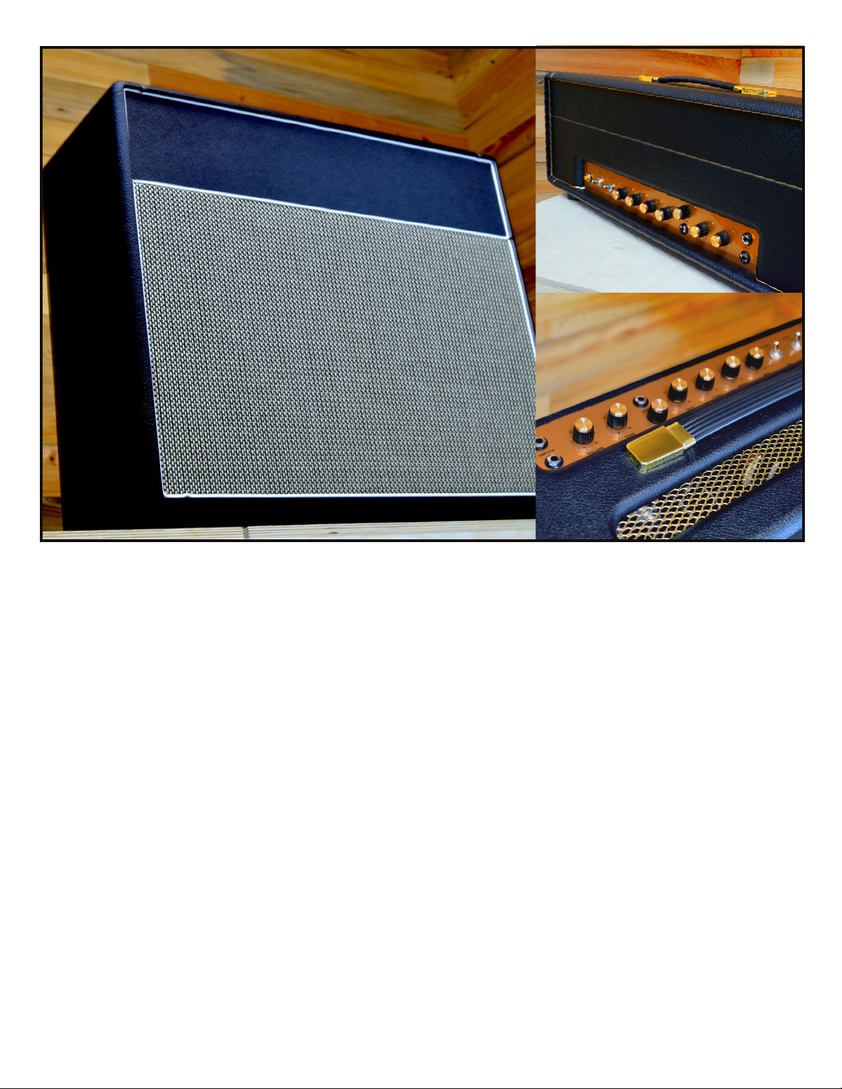
THE MOJOTONE
BRITISH STYLE
WATT
18WATT TMB
1X 12 COMBO AMP / AMP HEAD
ojotone’s 18watt TMB Amplifier Kit addresses a
M
common mod made to a classic circuit, but with a few
new avors of our own. The 18watt TMB is based on the
circuit used in vintage Marshall models 1958, 1973, and
1974 (more affectionately known as the ‘18-watters’.)
These original Marshalls were only produced between the years
1965 and 1967, but were highly sought-after for having massive
sounding JTM-45-like tones in a smaller, more manageable
package. Because they were produced in comparatively low
quantities, these amps still remain a ‘lost ark’ today.
18-watters became popular studio amps for many players
and were used, at times, by everyone from Gary Moore, to
The Pretenders, to AC/DC. Over the years, some players have
reported having no use for the amp’s original tremolo channel
and have opted to replace the tremolo controls with a 3-band
EQ, since the original amps were only equipped with a
single tone control for each channel. In the Mojotone version,
we have done just this. We have integrated the entire preamp
section and the tone stack from our British 800 kit (based on
the original Marshall JCM 800 circuit) for a lean and mean,
hot-rodded gain sound. We have also integrated a master
volume control so this monstrous sound can be harnessed
and used in any size room.
Two EL84s give the amp’s normal channel a warm and
round character which, when the volume is pushed higher,
begins to break up into a smooth grind perfect for blues rock
and classic rock rhythm sounds. On the dirty channel, one
can access screaming lead tones perfect for everything from
dim dirty grunge all the way to saturated hair metal sustain!
With our TMB mod in place, this take on a classic beast
now has a normal channel with high sensitivity and low
sensitivity inputs as well as a single volume and single
tone control; the second channel has a single input with
volume, treble, middle, and bass controls. And don’t
forget about the master volume!
Page 3

CONTENTS
SECTION 1: SAFETY PG.3
SECTION 2: TOOLS PG.3
SECTION 3: PARTS INVENTORY PG.4
SECTION 4: COMPONENT IDENTITY & ORIENTATION PG.5
SECTION 5: CHASSIS ASSEMBLY PG.6
SECTION 6: TRANSFORMER WIRING PG.8
SECTION 7: COMPONENT WIRING PG.10
SECTION 8: BOARD ASSEMBLY & INSTALLATION PG.10
SECTION 9: WIRING THE SOCKETS, JACKS & POTS PG.12
SECTION 10: Rear panel component installation & wiring PG.14
SECTION 11: SPEAKER WIRING & INSTALLATION PG.15
SECTION 12: INITIAL CHASSIS TESTING PG.15
SECTION 13: CHASSIS INSTALLATION & final assembly PG.16
SECTION 14: SOUND TEST PG.17
SECTION 15: TROUBLESHOOTING PG.17
MORE FROM MOJOTONE PG.18
All content included in this book including text, graphics and images is the property of Mojotone, LLC and protected by U.S. and international copyright laws. The collection, arrangement and assembly of all
content in this book is the exclusive property of Mojotone, LLC and protected by U.S. and international copyright laws. You may not copy, reproduce, distribute, publish, display, perform, modify, create derivative works, transmit, or in any other way exploit any part of copyrighted material without permission from Mojotone, LLC .
Copyright © 2019 Mojotone, LLC
Page 4
SECTION 1:
SAFETY
SAFETY FIRST! ELECTRONICS CAN BE DANGEROUS AND MUST BE TREATED WITH RESPECT. ANY CIRCUIT THAT WORKS WITH 120 VAC POWER FROM AN
ELECTRICAL OUTLET IS ESPECIALLY DANGEROUS AND COULD POTENTIALLY KILL YOU. HERE ARE SOME SAFETY GUIDELINES TO KEEP YOU SAFE AS YOU WORK:
Never work on a circuit while power is applied.
Do not connect power to a circuit until the circuit
is nished and you have carefully checked your
work (twice).
If you smell anything burning, immediately
disconnect the power and examine your circuit to
nd out what went wrong.
Keep your work area dry and organized.
Be careful around large capacitors. They can
continue to hold voltage long after they are disconnected from power. Discharge electrolytic capacitors if power has been applied to the unit.
SECTION 2:
Be especially careful when you solder. A hot
soldering iron can easily burn you.
Always work in a well-ventilated space.
Have safety equipment such as a re extinguisher,
a rst-aid kit and a phone nearby.
Be Patient! Rushing through any type of techni-
cal work just leads to frustration and compounds
issues that can easily be avoided.
Tools
CERTAIN TOOLS ARE REQUIRED TO SUCCESSFULLY BUILD YOUR AMP. THE FOLLOWING TOOLS ARE RECOMMENDED TO COMPLETE YOUR PROJECT:
½” Nut Driver
Set of needle nose pliers (one with no grip and
one with serrated edge)
Wire Cutters
Wire Strippers
Soldering Iron & Solder
Adjustable Wrench
Phillips Head Screwdriver
Multimeter
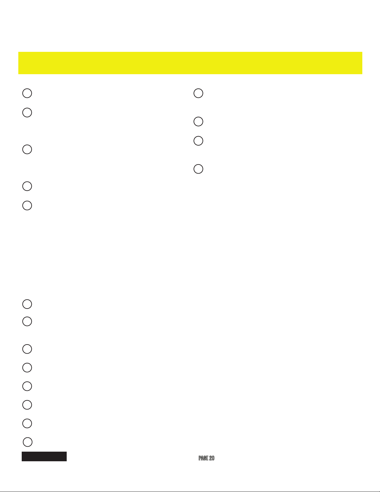
NEED A TOOL? DO YOU SEE SOMETHING ON THIS LIST THAT YOU DON’T HAVE? TURN TO PAGE 20 FOR A FULL LIST OF TOOLS, PARTS AND KITS TO ADD TO YOUR WORK BENCH.
www.mojotone.com
3
Page 5
ECC83S
EL 84 EZ 81
SECTION 3:
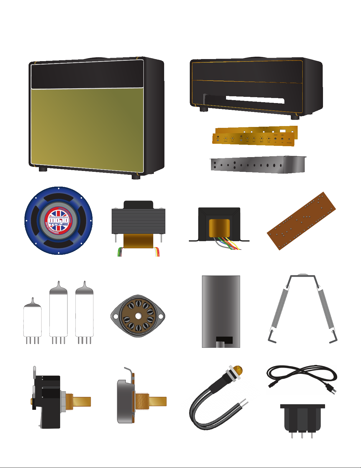
PARTS INVENTORY *optional based on order
(1) Void Free Birch Head Cabinet*
(1) Faceplates (front & back)*
(1) Void Free Birch Combo Cabinet*
(1) Mojotone British Vintage
30w, 12“, 8Ω Speaker*
(2) (1)
(3)
Vacuum Tubes*
(1) British Style 18 Watt
Power Transformer
(6) 9 pin Tube Socket
(1) Aluminum Chassis
(1) British Style 18 Watt
Output Transformer
(3) Tube Shield for ECC836
(1) Turret Board
(3) Spring Retainer for
EL84 & EZ81
(3) Impedance Selector Switch
w/ hardware
4
Potentiometers
(1) 1MA (vol. / tone), (1) 250kl (treb.)
(1) 25kb (mid.), (4) 500ka (vol. / tone)
BUILD. MODIFY. REPAIR.
(1) Indicator Lamp
w/ hardware
(1) 10‘ Removable Power Cord
(1) A/C Power Jack
Page 6
(8) Knobs
(1) 1/4'' Mono Plug
(1) Fuse Holder & Fuse
w/ hardware
(2) Toggle Switch
w/ hardware
Jacks w/ hardware
(4) J1 4-Lug Jack
(1) J2 2-Lug Jack
(2) Four-Lug Terminal
(2) Rubber
Grommets
(2) Ground
Tabs
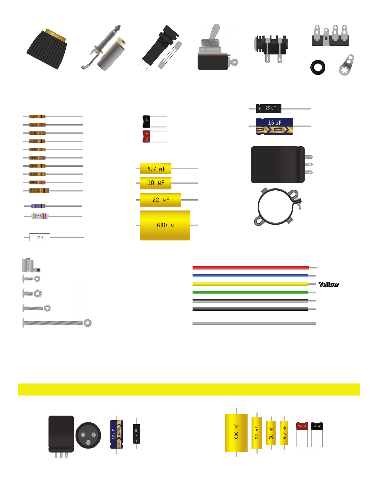
RESISTORS CAPACITORS
Carbon Composite
(2) 1/2W 1M
(1) 1/2W 2.7k
(2) 1/2W 5.1k
(1) 1/2W 10K
(1) 1/2W 47k
(3) 1/2W 68k
(7) 1/2W 100k
(7) 1/2W 470k
(3) 1/2W 820Ω
(2) 1W 100Ω
Metal Oxide
(2) 2W 10kΩ
(2) 2W 2.7k
Wire Wound
(1) 3W 130Ω
Silver Mica
Mojotone Dijon
HARDWARE
Standoffs for Turret Board
(20) 4-40 1/4'' Screw & Keps Nuts
(2) 8-32 1/4’’ Screw & Keps Nuts
(2) 6-32 1/2’’ Screw & Keps Nuts
(4) 10-32 11/2’’ Screw & Keps Nuts
(1) 47pf @ 500V
(2) 500pf @ 500V
(1) 4.7nf @ 630V
(4) 10nf @ 630V
(5) 22nf @ 630V
(1) 680nf @ 160V
WIRES
20 gauge Pre-Tinned PVC Coated Wire (4‘ of each color)
Copper Bus Wire (2‘)
(2) Sprague Atom
25µf @ 50V
(1) Mojotone
Electrolytic KingCap
16µf @ 475V
(2) Can Capacitor
32µf + 32µf
@ 500v
(2) Can Capacitor
Clamps
Red
Blue
Yellow
Green
Gray
Black
SECTION 4:
COMPONENT IDENTITY & ORIENTATION
ENSURE ALL POLARIZED CAPS ARE IN THE CORRECT ORIENTATION WHEN INSTALLING ONTO THE BOARD. THIS IS TYPICALLY DENOTED BY AN ARROW POINTING TOWARDS THE NEGATIVE
SIDE, OR A SMALL INDENTION ON THE POSITIVE SIDE.
SAFETY FIRST! A CAP IN THE WRONG ORIENTATION CAN EXPLODE! SO FOLLOW YOUR WIRING DIAGRAM AND PAY CLOSE ATTENTION WHEN ORIENTING YOUR POLARIZED CAPS.
POLARIZED
www.mojotone.com
NON-POLARIZED
5
Page 7
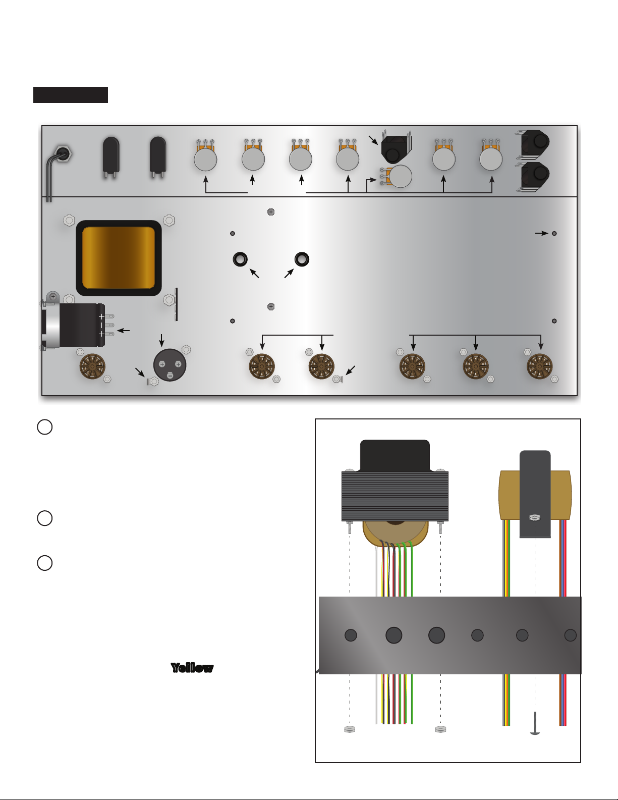
500 K 25 K 250 K 500 K 500 K
1 M
500 K
SECTION 5:
Chassis ASSEMBLY
PLEASE NOTE: ALL PARTS LISTED IN THE CHASSIS PREP SECTION STARTS AT ONE END OF THE CHASSIS AND COMPLETES ON THE OPPOSITE END, BOTH TOP AND BOTTOM.
FLATTENED VIEW OF INSIDE OF CHASSIS
INDICATOR
LAMP
MAINS SWITCH
STANDBY
J1 JACK
J1 JACK
POTENTIOMETERS
POWER TRANSFORMER
OUTPUT TRANSFORMER
RUBBER
GROMMETS
4 LUG
TERMINAL
CAN CAPACITOR
GROUND
TAB
9-PIN SOCKET
Mount the power transformer using its
pre-assembled hardware and your adjustable wrench. The transformer will be recessed through the rectangular cutout in the
“belly” of the chassis.
9-PIN TUBE SOCKETS
GROUND
TAB
J1 JACK
FOR TURRET BOARD MOUNTING
Install rubber grommets in holes for output
transformer leads.
Mount the output transformer using the (2)
8-32 x 1⁄4” screws and corresponding keps
nuts onto the outside of the chassis next to
the power transformer (output transformer
is not recessed). Install the transformer so
that the Red, Blue and Brown wires go
through the grommet furthest from the power transformer. The Yellow, Black, Green
and Orange go through the grommet closest to the power transformer. The screws
will go through the outside of the chassis,
and the nuts will be installed in the inside.
Use a screwdriver and adjustable wrench
to tighten.
6
BUILD. MODIFY. REPAIR.
Page 8

CHASSIS CROSS-SECTION FOR COMPONENT ASSEMBLY
POWER & STANDBY
SWITCH
FACEPLATE
CHASSIS
INDICATOR
LAMP
POTENTIOMETER
& KNOB
The faceplate will be secured by the washers and
nuts from the components being mounted through
it. Ensure the faceplate is straight before tightening
down the components and installing the knobs.
Mount indicator lamp using its pre-assembled
hardware. Unthread the hardware from the component and insert it through the chassis and corresponding faceplate cut out. Reapply hardware
and tighten with adjustable wrench and pliers.
INPUT JACKS 9-PIN
SOCKET
CHASSIS CROSS-SECTION FOR CAN CAP. ASSEMBLY
MOUNTING FROM
OUTSIDE CHASSIS
Mount your Main and Standby switches using
their pre-assembled hardware.
Mount potentiometers using their pre-assembled
hardware and 1/2” nut driver. Make sure potentiometers are mounted with their lugs facing up
towards the open end of the chassis.
PRO Tip: When mounting the pots, make sure the
toothed locking washer goes between the potentiometer and the chassis. The at washer will go on
the outside of the chassis and the nut will tighten
down.
Once you have the pots securely installed, turn the
shaft of the pot all the way counter-clockwise. Install the knob on each pot, making sure the pointer of the knob is pointing to “0” on the faceplate.
Use a small at head screwdriver to tighten the set
screw in the back of the knob securely on the pot
shaft. If the knob isn’t moving smoothly, loosen the
set screw, back the knob off of the pot 1/16‘‘ and
re-tighten.
MOUNTING FROM
INSIDE CHASSIS
Mount J2 input jacks using their pre-assembled
hardware and an adjustable wrench. Pay close
attention to the orientation of the jacks on the
wiring diagram.
PRO Tip: Pre-install and solder any resistors on the
jacks before mounting it to the chassis wherever
possible.
Mount 9-pin tube sockets using (4) 4-40 1⁄4” (for the
preamp tube sockets) and 4-40 x 3/8” (for the power
tube sockets and spring retainers) screws and keps
nuts and tighten down with adjustable wrench and
screwdriver. Be sure to mount the retainer springs on
the EL84 and EZ81 sockets and the ground tab.
Mount can capacitors using (4) 6-32 1/2“ screws and
keps nuts and tighten down with adjustable wrench
and screwdriver. Be sure to mount the ground tab.
www.mojotone.com
7
Page 9

SECTION 6:
TRANSFORMER WIRING
1M
68K
500 K 25 K 250 K 500 K 500 K
FROM OUTPUT TRANS.
10 K
2.7 K
RECTIFIER
TUBE SOCKET
EZ81
Twist all matching pairs of wires coming out of the
power transformer.
Measure length needed for each wire, allow yourself extra lead and cut to length. This will eliminate
excess wire and free up space in your chassis. Apply
this principle to all leads.
Prepare the two Red wires from the power trans-
former (HV secondary). Connect one wire to pin 1
and the other to pin 7 of the rectier tube socket.
NOTE: These wires carry AC voltage, so either
wire can go to either pin 1 or 7.
Prepare the Yellow and White wires from the
power transformer (5v rectier lament). Connect
the Yellow to pin 5 and White to pin 4 of the
rectier tube socket.
POWER
TUBE SOCKETS
EL84/6BQ5
socket closest to the power transformer.
Prepare the Black wire and connect to the mains
switch on the lug furthest from the power transformer.
Prepare the Green wire with the Yellow stripe.
Prepare the Red with the Yellow stripe and con-
nect both wires to the grounded lug on the terminal
strip.
Prepare the Black wire with the Red stripe and
connect it to an empty, non-grounded lug on the
terminal strip.
Prepare the Yellow wire with the White stripe
and connect it to an empty, non-grounded lug on
the terminal strip.
1 M
PHASE INVERTER
TUBE SOCKET
ECC83/12AX7
500 K
1M
PREAMP
TUBE SOCKETS
ECC83/12AX7
PRO Tip: On stranded wire, twist the stranded end
tight before tinning. This will make it easier to put
through the lug.
Prepare the two Green wires from the power
transformer (6.3v tube filament) and connect
them to the 5 and 4 pins on the power tube
8
Run the Black wire with the White stripe toward
the back panel of the chassis where the power plug
will be installed.
BUILD. MODIFY. REPAIR.
Page 10

On the output transformer the Red, Blue and Brown
wires are the primary and the Black, Yellow, Green
and Orange are the secondary.
Twist the Blue and Brown wires together and run
them between the two output sockets.
output tube socket furthest from the power transformer.
Prepare and connect the Red wire to the left
(+) terminal of the can capacitor that is installed
between the rectier socket (EZ81) and the power
tube socket (EL84).
Prepare and connect the Brown wire to the 7 pin of
the output tube socket closest to the power transformer.
Prepare and connect the Blue wire to the 7 pin of the
POWER TRANSFORMER SCHEMATIC OUTPUT TRANSFORMER SCHEMATIC
RED (12”)
290V @ 120MA
BLACK/RED (12”)
240V
RED/YELLOW (12”)
290V @ 120MA
BLACK/WHITE (12”)
120V
0V
BLACK (12”)
FOR 120V OPERATION: USE BLACK LEAD AND BLACK/WHITE LEAD
FOR 240V OPERATION: USE BLACK LEAD AND BLACK/RED LEAD
RED (12”)
GREEN (12”)
GREEN/YELLOW (12”)
GREEN (12”)
WHITE (12”) 6V 2A
YELLOW/WHITE (12”) 5V 2A
YELLOW(12”) 0V
6.3V @ 3A
Run the secondary wires toward the rear panel
where the impedance selector will be installed.
Double check wiring and begin soldering.
BLUE (12”)
RED (12”)
BROWN (12”)
ORANGE 16Ω (12”)
GREEN 8Ω (12”)
YELLOW 4Ω (12”)
BLACK 0 (12”)
pro tip: SOLDERING BASICS
SOLDERING IS AN ESSENTIAL SKILL FOR EVERY LEVEL OF AMP BUILDER. HERE ARE A FEW TIPS FROM THE AMP PROS AT MOJOTONE.
SAFETY FIRST! THE SOLDERING IRON TIP REACHES A TEMPERATURE OF 400˚
HEATED. ALWAYS WORK IN A WELL VENTILATED AREA.
Prepare the joint to be soldered. Strip PVC coating
1
/2 ‘‘ from end of wire, hook your leads into lugs or
turrets, twist leads together, etc.
Tin (apply solder to) the tip of the soldering iron.
This will keep it from oxidizing and prolong the life
of your soldering tip. Wipe excess on sponge.
Clean the tip often while soldering. This will help
the iron heat more consistently and evenly.
Be sure to use clamps or tweezers if needed to
hold the components to be soldered in place.
www.mojotone.com
C
SO NEVER DIRECTLY TOUCH IT OR ANY COMPONENT THAT YOU ARE SOLDERING WHEN IT IS
Touch the iron directly on the joint to be soldered
for about two seconds to get it hot enough to melt
the solder.
Touch the solder to the joint. As it melts let it ow
onto the joint to create a solid bond.
Lift the solder off rst and then remove the iron
from the component.
Another method is to tin the stripped wire and then
touch it directly to the heated component. Some
wires will be pre-tinned. They will have a shiny
silver layer twisted around the wire.
9
Page 11

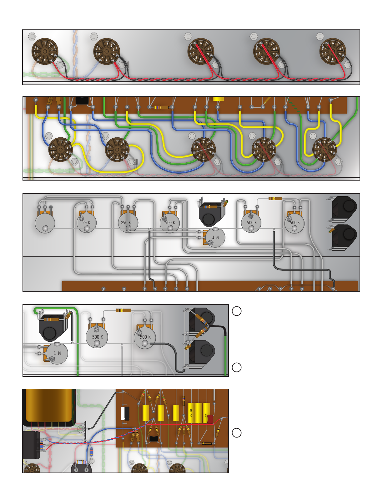
SECTION 7:
500 K 25 K 250 K 500 K 500 K
1 M
500 K
2.7 K
68K
10 K
10 K
1M
Component wiring
Connect The 10k metal oxide resistor between the
Positive (+) terminals on the can capacitor mounted
from the inside, and the 2.7k metal oxide resistor be-
tween the positive (+) terminals on the can capacitor
mounted from the outside.
Prepare the White and Yellow wire and twist to-
gether for the standby switch. Connect the Yellow
wire from the LEFT terminal of the switch to the
3 pin on the rectier tube socket. White from the
right terminal to the LEFT (+) terminal on the can
capacitor mounted from the outside of the chassis.
Prepare the Black wire for the mains switch. Con-
nect to the left terminal of the switch and run it to
where the fuse holder will be installed.
Connect one wire from the indicator lamp to the
RIGHT terminal on the mains switch. Run the other
wire to where the power plug will be installed.
Prepare the Blue and Green wire for the can capacitor mounted from the inside of the chassis. Connect
the Blue wire from the RIGHT positive (+) terminal
to an open, non-grounded, lug on the terminal strip.
Connect the Green wire from the Bottom negative (-)
terminal to the grounded lug on the terminal strip.
Prepare bare wire and connect from the BOTTOM
negative (-) terminal on the can capacitor mounted
from the outside of the chassis to the closest ground
lug. Connect a 10k metal oxide resistor from the
RIGHT positive (+) terminal to the same lug the
Blue wire is connected to on the terminal strip.
Double check wiring and solder.
SECTION 8:
BOARD ASSEMBLY & INSTALLATION
SAFETY FIRST! BE SURE TO TAKE NOTE OF POLARIZED CAPA CITOR ORIENTATIO N FOR THE 16 UF CAP, AND (2) 25UF CAPS.
Begin by applying traces (or “jumper wires”) to
the board.
PRO Tip: Utilize the different sections on the post
of the turret when attaching your wires and components. This makes for easier soldering and repair.
Once jumper wires are in place, follow wiring diagram
to create leads where necessary. These will be the wires
that go out from the component board to other compo-
10
BUILD. MODIFY. REPAIR.
nents in the circuit. Insert these leads down through the
front of the board and bend around back to secure.
PRO Tip: Use the included Wiring Diagram to
approximate lead lengths.
Starting at one end of the front side of the board,
identify the necessary components for each turret
connection and begin placing the leads into the
hole on top of the turret.
Page 12

10 nF
4.7 nF
22 nF
22 nF
22 nF
100K
100K
820Ω
10K
47K
470K
470K
470K
470K
16uF
22 nF
22 nF
680 nF
500 pF
500 pF
25uF
+
2.7 K
820Ω
100K
100K
2.7 K
PRO Tip: When a capacitor and resistor are both
running between the same turrets, you can twist
their leads, one around the other, and solder to
Once all components, jumpers, and leads are in
place, start at one end of the board and begin sol-
dering every turret.
form a solid mechanical connection.
Make Sure you don’t have any bad or “cold” solder
joints by lightly pulling each wire after solder has set.
CROSS-SECTION OF TURRET BOARD CAPACITOR AND RESISTOR TWISTED TOGETHER
JUMPER WIRES AND LEADS TO CHASSIS COMPONENTS
COMPLETED TURRET BOARD
470K
5.1K
470K
5.1K
47K
130 Ω
+
25uF
100 Ω
10 nF
100 Ω
100K
47 pF
100K
10 nF
10 nF
470K
22 nF
22 nF
22 nF
500 pF
470K
820Ω
100K
47K
500 pF
100K
22 nF
470K
470K
820Ω
2.7 K
10K
16uF
470K
22 nF
100K
4.7 nF
10 nF
100K
www.mojotone.com
2.7 K
680 nF
25uF
+
11
820Ω
Page 13

Locate the four small pre-drilled holes in the
COMPLETED
TURRET BOARD
STANDOFFS
chassis for mounting the turret board. Install
a turret board standoff on each hole using the
1/4‘‘ 4-40 screws.
Line the mounting holes on the turret board with
the turret board standoffs and secure using the
1/4‘‘ 4-40 screws.
SECTION 9:
WIRING THE SOCKETS, JACKS & POTS
TUBE SOCKET FILAMENT WIRING:
Pro Tip: This is a high gain preamp and is more
sensitive to lament hum from wiring lead dress. Take
care that signal wires are routed away from the lament
wirings and previous gain stages.
Twist tightly together a length of about 3’ of Red and
Black wire to start wiring the tube laments. Starting
with the power tube that is closest to the rectier tube,
prepare and connect the twisted wire between the tube
sockets.
PRO Tip: Make sure the power tube laments are “in
phase”. This means that the lament wires (Red and
Black twisted wire running between the power tubes
sockets) must connect to the corresponding pins between the sockets. Pin 4 to pin 4, Pin 5 to pin 5. Preamp
tubes do not have to be in phase.
When wiring the preamp tubes, Be sure to keep the
Red wires close together and centered when running
them across the tube socket to pin 5. Also note that there
is a jumper between pins 4 & 5.
PRO Tip: Since there is a wire connected to the 5 pin,
you can achieve the jumper wire to the 4 pin by stripping the wire back further, running it through the 5 pin
and reach to the 4 pin. Solder the wire to both pins. Use
this method on any jumper on the tube sockets.
“INPUTS” jacks. Connect the other from pin 2 and
run toward the “MASTER” jack.
POTENTIOMETER WIRING:
Prepare the bus wire that will mount across the back of
all the pots. Start from the “BASS” control on the left side
and solder the wire on the back of each pot. This will
provide a place to run to ground since the pots are all
grounded to the chassis.
Prepare the two Black wires and connect from
the board to the ground buss wire that is installed
on the back of the pots.
Follow the wiring diagram and begin wiring the pots on the
front of the chassis. Start from the left “BASS” control and
work your way across the chassis towards the input jacks.
INPUT JACK WIRING:
Prepare the Green signal wire from pin 2 of the
preamp tube and connect it to the rear left lug on
the “MASTER” input jack.
Prepare the three jumper wires and connect to the
“INPUTS” input jacks as shown.
Prepare the two Black ground wires and connect
to the “INPUTS” input jacks as shown.
TUBE SOCKET WIRING:
Follow the wiring diagram and begin wiring the tubes
sockets starting from the power tubes and work your
way across the chassis towards the preamp tubes.
Prepare two Green wires and connect one to pin
7 of the far right preamp tube and run toward the
12
Prepare the two 68K resistors and connect to the
“INPUTS” input jacks as shown. Then twist the other ends together.
Prepare the Green signal wire from pin 7 of the preamp tube and connect at the junction of the two 68K
resistors. Trim the excess wire from the 68K resistors.
BUILD. MODIFY. REPAIR.
Page 14
1 M
500 K
10 nF
10 nF
10 nF
10 nF
4.7 nF
22 nF
22 nF
22 nF
100K
100K
100K
100K
820Ω
820Ω
10K
47K
47K
470K
470K
470K
470K
470K
470K
470K
5.1K
16uF
22 nF
22 nF
680 nF
47 pF
500 pF
500 pF
25uF
+
100 Ω
100 Ω
25uF
+
130Ω
2.7 K
5.1K
820Ω
100K
100K
2.7 K
68K
100K
1M
68K
68K
1M
500 K 25 K 250 K 500 K 500 K
1 M
500 K
10 nF
4.7 nF
100K
820Ω
10K
470K
470K
470K
16uF
22 nF
22 nF
680 nF
500 pF
25uF
+
2.7 K
820Ω
100K
100K
2.7 K
68K
100K
1M
68K
68K
1M
1 M
500 K
10 nF
10 nF
10 nF
10 nF
4.7 nF
22 nF
22 nF
22 nF
100K
100K
100K
100K
820Ω
820Ω
10K
47K
47K
470K
470K
470K
470K
470K
470K
470K
5.1K
16uF
22 nF
22 nF
680 nF
47 pF
500 pF
500 pF
25uF
+
100 Ω
100 Ω
2.7 K
5.1K
820Ω
100K
100K
2.7 K
68K
100K
1M
68K
68K
1M
TUBE SOCKET FILAMENT WIRING
TUBE SOCKET WIRING
POTENTIOMETER WIRING
1M
68K
100K
INPUT JACK WIRING
CAN CAPACITOR WIRING
500 K 25 K 250 K 500 K 500 K
1 M
CAN CAPACITOR WIRING:
10 K
68K
1 M
100K
500 K
470K
130 Ω
5.1K
25uF
+
100Ω
100Ω
10 nF
100K
47 pF
5.1K
470K
10 nF
10 nF
100K
1M
500 K
10 K
2.7 K
www.mojotone.com
68K
68K
1M
47K
22 nF
470K
470K
820Ω
22 nF
22 nF
47K
500 pF
100K
500 K
1M
Prepare the Blue wire and connect
from the can cap mounted between
the rectier tube and power tube, to
the turret where the two 100 Ohm 1
watt resistors meet.
Prepare the Black wire and con-
nect from the grounded lug terminal,
mounted by the power transformer,
to the turret closest to the front of
the chassis where the 130 Ω resistor
/ 25uf capacitor are mounted.
Prepare the Blue and Red wires
and connect from the can capacitor mounted on the left side of the
chassis to the two points on the
board as shown.
13
Page 15

500 K 25 K 250 K 500 K 500 K
1 M
PREAMP TUBE
9 PIN SOCKET
12AX7
PHASE INVERTER
9 PIN SOCKET
12AX7
POWER TUBE
9 PIN SOCKETS
EL84
RECTIFIER TUBE
9 PIN SOCKET
EL84
CAN CAPACITOR
32µF + 32µF
@500V
BRITISH STYLE 18watt
POWER TRANSFORMER
INDICATOR LIGHT
MAINS SWITCH STANDBY SWITCH
GAINTREBEL
MASTER
BASS
J2 INPUT JACK
10 nF
10 nF
10 nF
22 nF
22 nF
22 nF
100K
100K
100K
100K
820Ω
820Ω
10K
47K
47K
470K
470K
470K
470K
470K
470K
5.1K
16uF
22 nF
47 pF
500 pF
500 pF
100 Ω
100 Ω
2.7 K
2.7 K
5.1K
68K
100K
10 K
10 K
1M
130 Ω
25uF
+
CAN CAPACITOR
32µF + 32µF
@500V
SECTION 10:
REAR PANEL COMPONENT INSTALLATION AND WIRING
FROM INDICATOR LAMP
FROM MAINS SWITCH
FROM POWER TRANSFORMER
TO GROUND TAB TO GROUND TAB
FUSE HOLDER
A/C POWER JACK
Install rear faceplate, fuse holder, impedance se-
lector and speaker jacks on the back of the chassis
using included hardware. Make sure the impedance
selector is snug so that it does not rotate when you
are switching between different output impedances.
Snap in A/C Power Jack into chassis with the center
pin oriented closest to the inside of the chassis.
FROM OUTPUT TRANSFORMER
IMPEDANCE SELECTOR
J1 SPEAKER JACK
J2 SPEAKER JACK
IMPEDANCE
SELECTOR
SWITCH
A/C POWER
JACK
Follow the wiring diagram and begin with wiring
the fuse holder and working to the right towards
the speaker jacks.
Install the knob on the impedance selector, Note which
color wire that the selector tab is pointing to, and align
the knob to that number on the back panel, tighten the
set screw. (Yellow 4 Ω, Green 8 Ω, Orange 16 Ω).
SECTION 11:
FUSE HOLDER
& FUSE
Use a small at head screw driver to remove the
fuse holder cap. Install the fuse into the cap and
reinstall into the fuse holder, push in and twist to
the right about a quarter turn.
SPEAKER WIRING & INSTALLATION (For Combo Amp only)
SPEAKER WIRE HARNESS ASSEMBLY:
Twist the two 15” lengths of black and white 18
gauge stranded wire together.
Push the insulation back about 1⁄2” from both wires
on one end and tin them.
Install the clear plastic shielding over the wiring,
then install the cover on the jack.
On the other end of the wiring harness, push back
the insulation on the wires by 1⁄2”, twist and tin them.
SPEAKER WIRE HARNESS ASSEMBLY
Unscrew the cover off of the 1⁄4” plug. Solder the
white wire to the tip terminal. Solder the black wire
to the sleeve as shown in the illustration.
Bend the two retaining tabs over to hold the wires
to the jack.
14
BUILD. MODIFY. REPAIR.
Page 16

With a pair of needle nose pliers, take the tinned
wire and make a small “hook” on both the white &
black wires.
Insert the white wire “hook” into the positive (+)
terminal on the back of the speaker. Use the needle nose pliers to carefully crimp the “hook” on the
terminal, forming a mechanical connection. Then
solder the wire to the terminal. Repeat the same process with the black wire on the negative (-) terminal.
SPEAKER INSTALLATION:
Remove the four mounting screws from the speaker bafe.
With the cabinet laying face down, place the
speaker on the bafe, line up the speaker mounting
holes with the holes on the bafe.
Finger tighten the mounting speaker screws. Starting with the top left screw, tighten with a screwdriver, then tighten the screw diagonally from it.
Then tighten the remaining screws in the same way.
Remove the upper and lower back panel of the
cabinet.
Mounting holes for the chassis have already been
drilled on the upper back panel.
SECTION 12:
INITIAL CHASSIS TESTING
Reinstall the lower back panel.
Starting from the left side of the chassis, ensure
all solder joints and connections are good. Physically
inspect every tube socket closely, making sure there
are not any extra wires touching other pins.
Look and listen for loose hardware by shaking chassis.
Ensure chassis is free from debris before plugging
in. Check for pinched or burnt wire insulation.
Adjust lead dress so it is easy to see components.
Power on amp without the tubes installed.
Using a multimeter set to AC voltage, check the
power transformer secondary AC voltages (at tube
www.mojotone.com
socket for laments). This will be pins 4 and 5 and pin
9 on the preamp tubes and pins 4 and 5 on the EL84’s.
Turn off the amp and install the EZ81/6CA4 rectier tube.
Turn on amp, do NOT turn on the Standby switch yet, and
allow it to warm up (approximately one minute). Watch
for any kind of arcing or smoke from any component
or transformer. If you see anything, shut down the amp
immediately. Disconnect the amplier from wall socket,
check voltages on the lter capacitors (DC voltage), make
sure they are drained, and then recheck your wiring.
Check the B+ voltages on pin 3 on the rectier socket.
Turn the Standby Switch to ON. Watch for any kind of
15
Page 17

ECC83S ECC83SECC83S
ONBASSMIDDLETREBLEGAINTONEVOLUME
MASTERINPUTS
STANDBYONMAINS
INDICATOR
EL 84EL 84
EZ 81
arcing or smoke from any component or transformer.
If you see anything, shut down the amp immediately. Disconnect the amplier from wall socket, check
voltages on the lter capacitors (DC voltage), make
sure they are drained, and then recheck your wiring.
SAFETY FIRST! THERE ARE NOW HIGH VOLTAGES
PRESENT IN THE AMPLIFIER.
the Standby switch to ON. Check the B+ voltages
on pin 1 and pin 6 of the preamp tubes.
Turn the amp back to Standby and then turn off the
amp. Install the output tubes. Plug in the speaker.
Turn the amp on and check for proper lament operation.
Set your multimeter to its highest DC Voltage setting.
Attach the ground / common probe to the metal chassis. With one hand, take the positive (Red) probe and
carefully measure the voltages on the (+) terminals on
the can capacitors. Then measure the voltage at the 16uf
capacitor on the board. The voltages will be higher than
the voltage readings on the wiring diagram due to the remaining tubes not being installed in the circuit. If you do
not have voltages at these points, power down the amplier, allow the capacitors to drain, DO NOT short them to
ground as this can damage the capacitors or cause them
to explode. Test with your multimeter to make sure the
voltages are below 10V DC before working on the amp.
Turn the amp to Standby and then turn off the amp.
REMEMBER, if you have not drained the capacitors, there are still high voltages present.
Install the preamp tubes, then power up the ampli-
er and ensure the laments are working. Then turn
Turn the Standby switch to ON. Check the voltages at
the test points on the wiring diagram. Check the voltage
on pin 2 of each EL84 tube. Ensure the voltage reading
is near 0V +/- 50mV to avoid “red-plating” of the tubes.
PRO Tip: Red plating occurs when too much cur-
rent is applied to the plate (anode) of a vacuum
tube. It will overheat and glow cherry red. Turn the
power off immediately if this happens.
Let the amp idle on for half an hour or so for the
chassis to be warm and do the bump test.
PRO Tip: A bump test is exactly what it means. Use a non
conductive tool, such as a wooden handle of hammer or
plastic handle of a screw driver, to hit the edge of the chassis or pick your amp up about an inch and drop it. Don’t
worry it won’t harm your amp. This helps you test for bad
solder joints and any loose hardware as well as lets you
know if there is a physical problem with one of your tubes.
Turn the amp back to Standby and then turn the amp off.
SECTION 13:
CHASSIS INSTALLATION & FINAL ASSEMBLY
COMBO CABINET
Turn the chassis over so that the open end is fac-
ing up. If you still have the tubes installed be VERY
careful not to break the tubes. Take the top back
panel and line up the pre-drilled mounting holes
with the hole on the wings of the chassis.
Secure the back panel to the chassis using the four
1-1/2” 10-32 screw and keps nuts.
Secure the EL84 power tubes and EZ81 rectier
with the spring retainers.
the back of the combo cabinet using the four machine
Install the preamp tube shields. Align the pins on the
tube base with the grooves in the tube shield. Press
them on to the tubes and turn a quarter turn to the right.
Install the back panel, with the controls facing up, into
16
BUILD. MODIFY. REPAIR.
screws that originally held the back panel in place.
Set the Impedance selector on the back of the
chassis to match the impedance of the speaker in-
stalled in the cabinet.
Page 18

Plug the speaker into the speaker jack closest to the im-
ECC83S ECC83SECC83S
ONBASSMIDDLETREBLEGAINTONEVOLUME
MASTERINPUTS
STANDBYONMAINS
INDICATOR
EL 84EL 84
EZ 81
ECC83S ECC83SECC83S
ONBASSMIDDLETREBLEGAINTONEVOLUME
MASTERINPUTS
STANDBYONMAINS
INDICATOR
EL 84EL 84
EZ 81
ECC83S ECC83SECC83S
EL 84EL 84
EZ 81
MAINS FUSE
MAINS INPUT
IMPEDANCE
4 8
16
SPEAKERS
pedance selector.
Carefully slide the chassis into the cabinet until the front
faceplate is ush against the front panel of the cabinet.
Plug in the power cord into the A/C jack on the back of
the chassis.
HEAD CABINET
Using a screwdriver, remove the four screws holding
the back panel on the cabinet.
SECTION 14:
SOUND TEST
Carefully turn the cabinet so that it is facing down.
Locate the mounting holes on the bottom of the cabinet.
Install the four 1-1/2” 10-32 screws into the bottom of
the cabinet, through the mounting holes in the chassis.
Secure the screws with the 10-32 keps nuts.
Re-install the rear panel on the cabinet. Plug in power
cord into A/C outlet.
SECTION 15:
TROUBLESHOOTING
Turn on the amp and let it warm up.
After warm-up, ensure the tubes are not “red plating.”
Rotate all controls fully and listen for noise. It
is normal to have some noise at high volume levels.
Plug in an instrument cable and listen for any
crackle, pops, strange oscillations or feedback.
Leave on for a while so the tubes and compo-
nents can “burn in” - (not literally)
ROCK OUT!!
CONGRATULATIONS!! YOU HAVE JUST BUILT YOUR VERY OWN MOJOTONE
18WATT TMB. THERE IS ONLY ONE ON THE PLANET THAT IS LIKE YOURS. WE HOPE
YOU HAVE ENJOYED THIS EXPERIENCE AND GAINED KNOWLEDGE TO HELP YOU
BECOME MORE CONFIDENT TO BUILD MANY MORE AMPS AND SPREAD YOUR
KNOWLEDGE.
DEPENDING ON THE ISSUE YOU HAVE, YOU WILL NEED TO DIAGNOSE WHICH PART
OF THE CIRCUIT IS FAULTY. TRY TO WORK THE PROBLEM ANALYTICALLY, YOU
CAN MAKE PROBLEMS WORSE OR CREATE NEW ONES BY DOING UNNECESSARY
REPAIRS. 99% OF THE TIME IT IS SIMPLE - A BAD SOLDER JOINT, NO SOLDER ON
JOINT, CAPACITOR IN BACKWARDS, ETC.
RESOURCE WEBSITES
www.ampwares.com The best resource with the most
extensive info on most vintage amps.
RESOURCE LITERATURE
Tube Guitar Amplier Essentials and All About
Vacuum Tube Guitar Ampliers by Gerald Weber
Truly must read books by Gerald Weber for any amp
tech. You can purchase these at Mojotone.
The Tube Amp Book By Aspen Pitman.
A great resource for schematics and basic tube info.
Comes with DVD that has over 800 schematics of vintage tube amp technology.
RCA Tube Receiving Manual
This is one of the books that really started the guitar amp craze.
Leo Fender used this very book to develop his rst amps.
SHARE YOUR BUILD WITH US WE WANT TO SEE YOUR FINISHED
AMP. SEND PHOTOS TO: SALES@MOJOTONE.COM
OR TAG US!!! @ MOJOTONE
@ MOJOTONE
www.mojotone.com
CONTACT MOJOTONE’S PRO TECHS
800-927-6656
tech @ mojotone.com
17
Page 19

Ready for your next build?
TWEED CHAMP 5F1 STYLE COMBO
Mojotone’s Tweed Champ Style Amp Kit is based on the beloved 5 watt amp from the
1950s. These amps were perfect for recording and were featured on a wide array of recordings from Joe Walsh’s “Rocky Mountain Way” all the way to Derek & the Dominos’
“Layla.” Modeled after the historic Class-A 6V6 platform, this amp delivers warm tones
that are harmonically rich and have a beautiful low volume crunch. SKU # G1TCK910
Class Type: Single Ended Class A All Tube Amplifier
Output: ~5W
Circuit: 5F1
TWEED DELUXE 5E3 STYLE COMBO
Mojotone’s Tweed Deluxe Style Amp is based on the popular 5E3 circuit from the 1950s and
is by far our most popular amplier. These amps were originally designed as medium power
amps that would allow a musician to plug in more than one amplied instrument at a time.
At higher volumes, this amp produces saturated tones that were adopted as signature tones
for the likes of Billy Gibbons, Neil Young, Don Felder, and Larry Carlton. SKU # G1FTD819
Class Type: Class A/B all Tube Amplifier
Output: ~15 watts
Circuit:5E3
MOJOTONE TWEED BASSMAN 5F6-A STYLE COMBO
Mojotone’s Tweed Bassman Style Amp is based on the late 50s 5F6-A circuit which seems
to be the most commonly used of the Bassman circuits. These 40 Watt amps are known
for their bold and pristine clean sounds as well as their classic unmistakable dirt. The
Bassman is extremely versatile and has been used by tons of iconic guitarists from Mike
McCready, of Pearl Jam fame, all the way to Stevie Ray Vaughan himself. SKU # G1TWK942
Class Type: A/B all Tube Amplifier
Output: ~40 watts
Circuit: 5F6-A
Bias Type: Cathode Biased
Build time: 4 hours
Difficulty:
Bias Type: Cathode Biased
Build Time: 5 hours
Difficulty:
Bias Type: Fixed
Build Time: 6 hours
Difficulty:
18
BLACKFACE Princeton REVERB® STYLE COMBO
The Blackface Princeton Reverb has been a staple in guitar tone since its inception in 1964.
The Princeton Reverb was essentially all the good parts of its predecessor, the Tweed Princeton, but with a long-spring reverb and tube-driven tremolo circuit added. Over the years the
Princeton Reverb has worked its way into the gear repertoire of many renowned guitarists
such as Ryan Adams, Larry Carlton, Glen Campbell, and Tommy Tedesco. SKU # G1BPR108
Class A/B All Tube Amplifier
Output: ~12-15 Watts
Circuit: AA1164
BLACKFACE DELUXE REVERB® STYLE COMBO
One of our most popular amps, the Mojotone Deluxe Reverb Style Kit, is based on arguably the most widely used guitar amp of all time. Just about every iconic guitarist imaginable has played through a Deluxe Reverb at some point or another, but this amp has been
specically touted by artists such as Mike Campbell, Vince Gill, Jackson Brown, and even
Elvis Costello. SKU # G1BDR092
Class Type: A/B All Tube Amplifier
Output: ~22 Watts
Circuit: AB763
BUILD. MODIFY. REPAIR.
Bias Type: Fixed
Build Time: 5 hours
Difficulty:
Bias Type: Fixed with an adjustable bias potentiometer
Build Time: 7 hours
Difficulty:
Page 20

BRITISH 18 WATT STYLE 1X12 COMBO
If you are looking for an amplier that is compact, lightweight, but powerful, this is the
jewel for you. It produces beautiful cleans and one of the best distortion tones ever produced. The 18 watt amplier is the epitome of perfect vintage Marshall® tone. SKU # G1BCK212
Class TYPE: A/B All Tube Amplifier
Output: ~18 Watt
Circuit: 1974
This kit produces similar tones to a 81-90 Marshall® JCM800 2204. SKU # G1800969
Class TYPE: A/B Tube Amplifier
Output: ~50 Watts
Circuit: 2204
This was the rst amplier Marshall® ever built, based off of the 5F6A circuit. Favored
by blues and rock guitarists, this amp can produce a warm sustain and elegant clean
tones, with a pronounced rectier “sag.” Played by guitar greats such as Angus Young
and Gary Moore. SKU # G145C228
Class TYPE: A/B all Tube Amplifier
Output: ~45 watts
Circuit: M45
Cathode Biased
Build Time: 6 hours
Difficulty:
Fixed Bias with an adjustable bias potentiometer
Build Time: 7 hours
Difficulty:
Bias Type: Fixed Bias w/ adjustable potentiometer
Build Time: 6 hours
Difficulty:
BRITISH 800 STYLE AMP
BRITISH 45 STYLE 2X12 COMBO
BLACKFACE SUPER REVERB® STYLE COMBO
Few amps have rivaled the commanding image and sound of the Super Reverb. Since
its introduction in 1963, the Super Reverb has remained highly sought-after due to its
unique tonal qualities and extreme versatility. Having a use on stages of all sizes and in
any studio situation, the Mojotone Super Reverb style amp has the potential to handle
literally any task at hand. SKU # G1BSR125
Class TYPE: A/B Tube Amplifier
Output: ~40 Watts
Circuit: AB763
Our Brownface Deluxe Style kits are modeled after the brown era model 6G3 from the
earlier 1960s. Great for recording or small gigs. The amp can go from a tweed clean/
dirty to a British style overdrive with the turn of the volume knob. Includes bias modulated tremolo. SKU # G1BFD067
Class TYPE: AB all tube amplifier
Output: ~15 watts
Circuit: 6G3
Bias Type: Fixed Bias w/ adjustable bias potentiometer
Build Time: 8 hours
Difficulty:
Bias Type: Fixed Bias
Build Time: 5 hours
Difficulty:
TWEED TWIN 5E8-A LOW POWER STYLE COMBO
Mojotone’s Tweed Twin Low Power Style Amp Kit is a complete tonal powerhouse.
Sporting 45 Watts of power, the amp has all the sweet, vocal qualities and rich dynamic
response as the original. Known for being a plug-and-play amp, the 5E8-A circuit has
been used most notably by Eric Clapton and has been said to ‘cut’ more than its higher
powered counterpart (Tweed Twin High Power). SKU # G1TTL031
Class Type: AB all Tube Amplifier
Output: ~45 watts
Circuit: 5E8-A
Bias Type: Fixed
Build Time: 6 hours
Difficulty:
BROWNFACE DELUXE STYLE COMBO
www.mojotone.com
19
Page 21

the
Workbench
Tools the Pros use
WORKBENCH TESTED. AMP PRO APPROVED. YEARS OF EXPERIENCE AND ENDLESS PASSION HAVE DRIVEN
OUR TEAM AT MOJOTONE TO CREATE THE QUALITY PRODUCTS THAT WE OFFER. NOW YOU CAN USE THE TOOLS
THAT WE DO IN YOUR SEARCH FOR THE PERFECT TONE.
MOJOTONE AMPLIFIER CHASSIS STAND
SKU# N4CHS021
KESTER ‘’44’’ ROSIN CORE SOLDER
SKU# 1000015a
WELLER ANTI-STATIC DE-SOLDER
PUMP SKU# N4TOL085
WELLER WTCPT TEMPERATURE
CONTROLLED SOLDERING STATION
SKU# N4TOL110
XCELITE 6-PIECE PRECISION
SCREWDRIVER SET SKU# N4TOL125
XCELITE ELECTRICAL CUTTING AND
STRIPPING PLIERS SKU# N4TOL113
MOJOTONE SYG A830L DIGITAL
MULTIMETER SKU# 4152015
GROOVETECH JACK/POT WRENCH
SKU# Q2GTJPT1757
XCELITE SERRATED LONG REACH PLIERS
SKU# N4TOL116
MOJOTONE PICKUP WINDING
MACHINE SKU# 4152015
RENE MARTINEZ 24-PIECE
MICRO-TIP SCREWDRIVER SET
SKU# Q2GTJPT1757
XCELITE 6” LONG NEEDLE NOSE PLIERS
SKU# N4TOL124
CONTACT & ORDERING INFO Follow
800-927-6656 sales@ mojotone.com
or
www.mojotone.com
Disclaimer: Mojotone, LLC makes no representations or warranties of any kind as to the information, content, procedures, materials or operation of this book. To the full extent permissible by applicable law,
MojoTone, LLC disclaims all warranties, expressed or implied, including but not limited to, implied warranties of merchantability or tness for any particular purpose. Mojotone, LLC will not be liable for dam-
ages of any kind arising from the use of this book, including but not limited to direct, indirect, incidental punitive and consequential damages.
137 WORTH BEVERAGE DR., BURGAW, NC 28425
 Loading...