

Page 1
MOJOTONE FX LOOP VERSION 2 Installation Manual
How to Install the Mojotone FX Loop to Your Amplifier’s Chassis
Note: The following steps should be performed with the amplifier’s power cable unplugged. Follow all
electrical safety guidelines including discharging the amplifier’s capacitors. If you do not feel
confident to perform the following installation steps, let a qualified technician complete the work. If
you continue, you do so at your own risk.
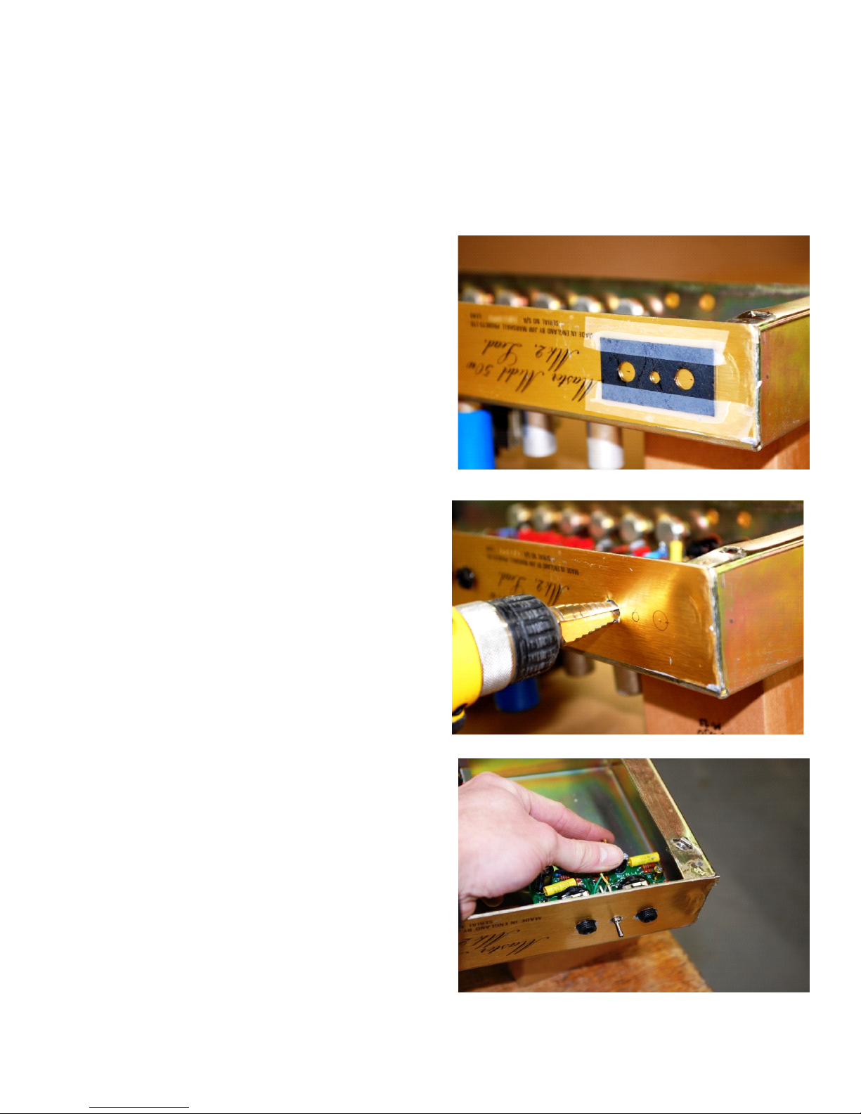
Step 1: Line it Up Start by placing the template on the
amplifier chassis where the FX Loop will mount.
Ideally, since the signal will be sent through it, the FX
Loop should be placed as far away from the output as
possible. As a test, place the FX Loop in the location
where it will be installed, and make sure it does not
physically interfere with any other part of the amplifier.
Trace the insides of the holes on the template onto
the amplifier’s chassis using a marker, pen, or pencil.
Step 2: Drill it Out Drill the holes with either a step bit
or a regular metal cutting bit. Holes for the Send and
Return should be 7/16” in diameter. The hole for the
Bypass should be 3/16“ in diameter.
Step 3: Pop it In Insure that the FX Loop fits into the
holes and sits flush against the amplifier chassis.
Again, make sure the FX Loop’s components are clear
of obstruction from any other part of the amplifier.
Use the supplied nuts to secure the FX Loop to the
amplifier chassis. Note that mounting the FX Loop
component side up will position the Send jack on the
left and the Return jack on the right. The opposite will
result if the FX Loop is mounted component side
down.
1
Page 2

Wiring the Mojotone FX Loop into Your Amplifier
Step 1: What's on the Board Locate on the FX Loop component board the pads for the:
• Power Supply (B+)
• Ground (GND)
• Signal In (IN)
• Signal Out (OUT)
• Return Trimpot (RET TRIM)
• Send Mute (SEND)
Step 2: Hook it Up Solder a jumper wire from the low-power side of the amplifier’s power supply line,
which is usually after the final filtering capacitor and drop resistor, to the B+ pad on the FX Loop
component board. This voltage should not be under 150V or over 350V. Solder a wire from the
Ground (GND) pad on the FX Loop component board to a ground that produces the least amount of
hum noise. This will usually be the cathode ground for the stage before or after the insertion location
of the FX Loop.
Choose a point in the signal path to break and insert the FX Loop. The circuit is optimized for a point
just before the driver or phase inverter stage. In our JCM800 test circuit, the FX Loop either goes
between the treble and the master potentiometers, or just before the coupling capacitor into the
driver or phase inverter stage (see the schematics below). Solder wires to the Signal In (IN) and
Signal Out (OUT) pads on the FX Loop board, and run them to the area of the preamp where the signal
path will be broken. If this is on a PCB of which you do not want to cut traces, pull the coupling
capacitor from the board, and use the remaining holes for the installation. Remember, however, to
place the capacitor in line with the return lead of the FX Loop. If there are no DC considerations where
you are adding the FX Loop in the board, then it can be added without capacitors. If you experience
any sort of failure on install with the board, it is likely there was a bias consideration that is being
changed by the installation, and the circuit will need to be isolated with capacitors. Also, notice
ground pads above the send and return pads. These are added for convenience when using shielded
wire.
2
Page 3

Step 3: Return Trim Decide how you want your FX Loop to function with respect to output level
control using a trim or chassis mount pot or a basic install by jumping the return trim pads. One or the
other must be performed in order to complete the circuit. For a basic install, solder a wire jumper
from one of the return trim pads to the other. This will complete the FX Loop circuit. For output level
control, solder the wiper of a 1M Ohm audio taper trimpot or an equivalent panel mount
potentiometer to the return trim pad furthest away from the switch, and solder the right-side pin of the
potentiometer to the other trim pad. Solder the final pin of the potentiometer to ground. This will
complete the FX Loop circuit. Resistors can also be soldered into the trim pads if a fixed control of
the return is desired. With stock components, installing the FX Loop in active mode will reduce your
signal 10dB after the buffer stage of the circuit. On return, the signal will go through a gain stage that
brings it back up 16dB. Therefore, the FX Loop will deliver a signal that is 6dB hotter. This can be
trimmed by using the return trim output control, with the output potentiometer on your effects rack if
you have one, or with your master volume.
Step 4: Send Mute (Optional) These pads make it possible to mute the FX Loop with a foot switch.
Simply wire the send pad to the tip and the ground pad to the sleeve of a 1/4” jack. A common foot
switch in a SPST normally open configuration will send the FX loop signal to ground when the signal
is to be muted.
Step 5: Modification (Optional) A signal flow is shown below. The FX Loop board can be re-
configured for other level considerations by adjusting the voltage dividers shown. To permanently
adjust the send to a higher level, simply increase the 470 Ohm resistor after the send buffer. To
permanently adjust the return gain up or down, just reduce or increase the 470k Ohm resistor after
the return gain. With regard to coupling capacitors, the FX Loop buffer input capacitor must be
retained in all cases since it blocks DC present at the input of the buffer. Assuming any gear you have
in the effects chain has a capacitor on the input, we did not utilize a coupling capacitor on the input of
the FX Loop. There should not be any DC on the input of the return stage. The output of the return
gain stage has a coupling capacitor which must be there to block high voltage into your amplifier
andacross the voltage divider used to set the level out of the FX Loop.
3
 Loading...