

Page 1

Installation Guide
C-75 Access Point/Sensor
Page 2

This page is intentionally left blank.
Page 3

Federal Communication Commission Interference Statement
This device complies with Part 15 of the FCC Rules. Operation is subject to the following two conditions: (1)
This device may not cause harmful interference, and (2) this device must accept any interference received,
including interference that may cause undesired operation.
This equipment has been tested and found to comply with the limits for a Class B digital device, pursuant to
Part 15 of the FCC Rules. These limits are designed to provide reasonable protection against harmful
interference in a residential installation. This equipment generates, uses, and can radiate radio frequency
energy and, if not installed and used in accordance with the instructions, may cause harmful interference to
radio communications. However, there is no guarantee that interference will not occur in a particular
installation. If this equipment does cause harmful interference to radio or television reception, which can be
determined by turning the equipment off and on, the user is encouraged to try to correct the interference by
one of the following measures:
Reorient or relocate the receiving antenna.
Increase the separation between the equipment and receiver.
Connect the equipment into an outlet on a circuit different from that to which the receiver
is connected. Consult the dealer or an experienced radio/TV technician for help.
FCC Caution: Any changes or modifications not expressly approved by the party responsible for compliance
could void the users authority to operate this equipment.
This transmitter must not be co-located or operating in conjunction with any other antenna or transmitter.
For operation within 5.15 ~ 5.25GHz / 5.47 ~5.725GHz frequency range, it is restricted to indoor environment.
The band from 5600-5650MHz will be disabled by the software during the manufacturing and cannot be
changed by the end user. This device meets all the other requirements specified in Part 15E, Section 15.407
of the FCC Rules.
FOR MOBILE DEVICE USAGE (>20cm/low power) Radiation Exposure
Statement:
This equipment complies with FCC radiation exposure limits set forth for an uncontrolled environment. This
equipment should be installed and operated with a minimum distance of 20cm between the radiator and
your body.
FOR COUNTRY CODE SELECTION USAGE (WLAN DEVICES)
Note: The country code selection is for non-US models only and is not available to all US models. Per FCC
regulations, all Wi-Fi products marketed in the US must be fixed to US operation channels only.
C-75 Installation Guide
3
Page 4

C-75 Installation Guide
4
Industry Canada Statement
This device complies with RSS-210 of the Industry Canada Rules. Operation is subject to the following two
conditions: (1) This device may not cause harmful interference, and (2) this device must accept any
interference received, including interference that may cause undesired operation.
Ce dispositif est conforme a la norme CNR-210 dIndustrie Canada applicable aux appareils radio exempts de
licence. Son fonctionnement est sujet aux deux conditions suivantes: (1) le dispositifne doit pas produire de
brouillage prejudiciable, et (2) ce dispositif doit accepter tout brouillage re , y compris un brouillage
susceptible de provoquer un fonctionnement indesirable.
Caution:
(i) the device for operation in the band 5150-5250 MHz is only for indoor use to reduce the potential for
harmful interference to co-channel mobile satellite systems;
(ii) high-power radars are allocated as primary users (i.e. priority users) of the bands 5250-5350 MHz and
5650-5850 MHz and that these radars could cause interference and/or damage to LE-LAN devices.
Avertissement:
(i) les dispositifs fonctionnant dans la bande 5 150-5 250 MHz sont reserves uniquement pour une utilisation
a linterieur afin de reduire les risques de brouillage prejudiciable aux systemes de satellites mobiles utilisant
les memes canaux;
(ii) De plus, les utilisateurs devraient aussi etre avises que les utilisateurs de radars de haute puissance sont
designes utilisateurs principaux (c.-a-d., quils ont la priorite) pour les bandes 5 250-5 350 MHz et 5 650-5
850 MHz et que ces radars pourraient causer du brouillage et/ou des dommages aux dispositifs LAN-EL.
FOR MOBILE DEVICE USAGE (>20cm/low power)
Radiation Exposure Statement:
This equipment complies with IC radiation exposure limits set forth for an uncontrolled environment. This
equipment should be installed and operated with a minimum distance 20cm between the radiator and
your body.
Declaration d exposition aux radiations:
Cet equipement est conforme aux limites d exposition aux rayonnements IC etablies pour un environnement
non controle. Cet equipement doit @tre installe et utilise avec un minimum de 20 cm de distance entre la
source de rayonnement et votre cmps.
Page 5
C-75 Installation Guide
5
About this Guide
Note Mojo server, unless the server name or
type is explicitly stated.
Old Name
New Name
AirTight Management Console
Mojo Wireless Manager
AirTight WIPS
Mojo AirTight
Mojo Studio/ AirTight Cloud
Mojo Launchpad
AirTight Guest Manager
Mojo Guest Manager
AirTight Single Sign-On (SSO)
Mojo One
This installation guide explains how to mount the C-75 access point (AP) and the various configuration details.
Important! Please read the EULA before installing the C-75. Installation constitutes your acceptance of the
terms and conditions of the EULA.
Intended Audience
This guide can be referred by anyone who wants to install and configure the C-75 access point.
Document Overview
This guide contains the following chapters:
1. Package Contents
2. C-75 Overview
3. Installing the C-75
4. Manually Configuring C-75
5. Config Shell Commands
6. Troubleshooting
Product/Feature Name Changes
The following table summarizes the product and feature name changes:
Product and Documentation Updates
To receive important news on product updates, please visit our website at http://www.mojonetworks.com. We
continuously enhance our product documentation based on customer feedback. To obtain the latest copy of
this document, visit http://www.mojonetworks.com/home/support.html.
Contact Information
Mojo Networks, Inc.
339 N, Bernardo Avenue, Suite #200, Mountain View, CA 94043
Tel: +1 650-961-1111 Fax: +1 650-963-3388
For technical support, send an email to [email protected].
Page 6
C-75 Installation Guide
6
Package Contents
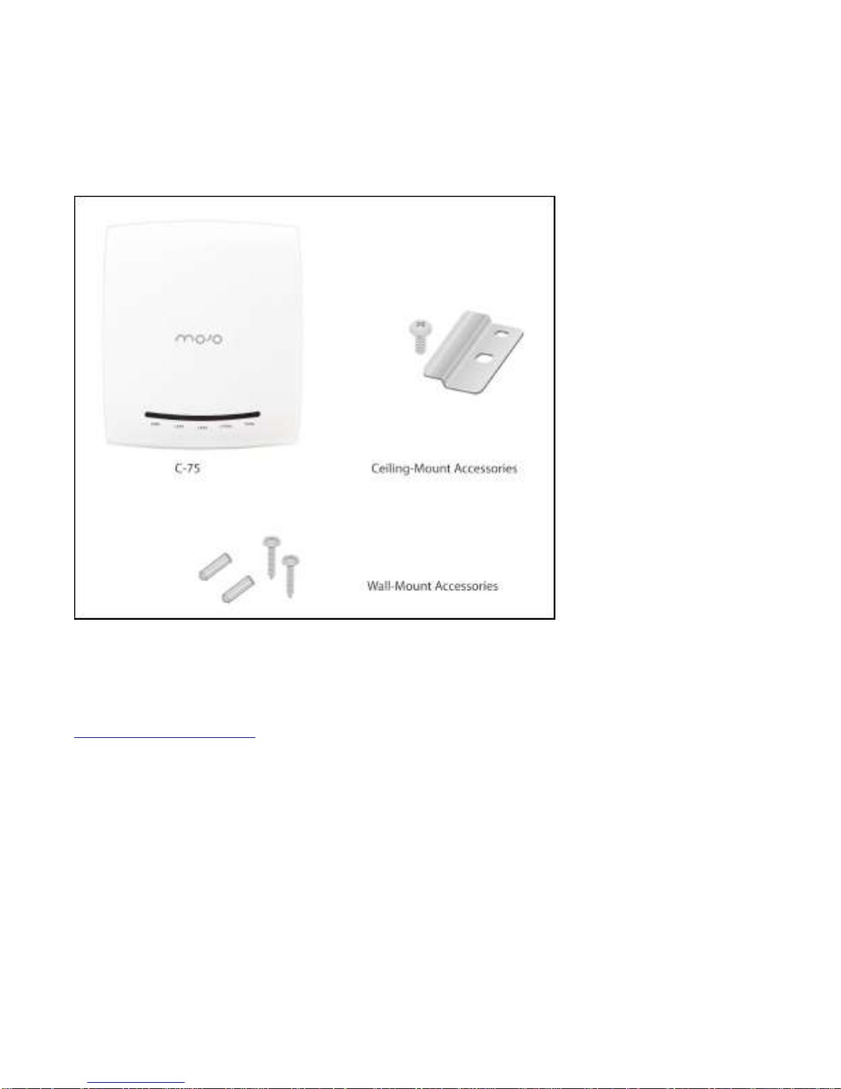
Please ensure that the items shown in Figure 1-1 are included in the C-75 device package:
Figure 0-1 C-75 Package Contents
Note: The MAC address of the device is printed on a label at the bottom of the product and the packaging box.
Note down the MAC address, before mounting the device on the ceiling or at a location that is difficult to
access.
If the package is not complete, please contact Mojo Networks, Inc. technical support at
[email protected], or return the package to the vendor or dealer where you purchased the product.
Page 7
C-75 Installation Guide
7
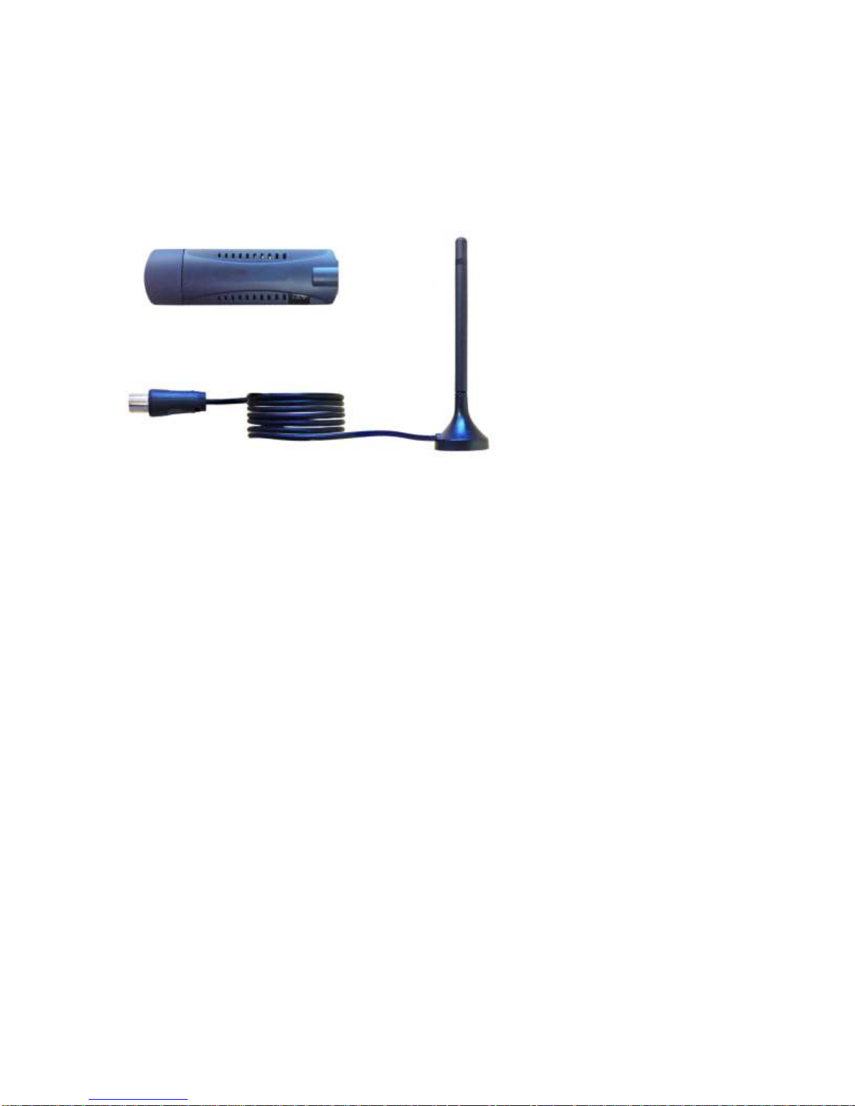
Optional Cellular Activity Detection Device
The cellular activity detection device is an optional USB device used to detect cellular activity. This is to be
plugged into a C-75 device.
Figure 0-2 Cellular Activity Detection Device
Page 8
C-75 Installation Guide
8
C-75 Overview
Power
LAN1
1
LAN2
2.4 GHz
5 GHz
Description
Solid
Green
Solid
Green
On/Off
Any
Any
The AP is powered on and is working normally.
The AP is connected to the server.
Solid
Green
Slow
Blink
On/Off
Slow
Blink
Any
The AP upgrade is in progress.
Solid
Orange
Solid
Green
On/Off
Any
Any
The AP is unable to get Ethernet link.
C-75 is a 3x3 802.11a/b/g/n/ac access point/sensor. This chapter provides an overview of the C-75 and
describes front and the rear panels.
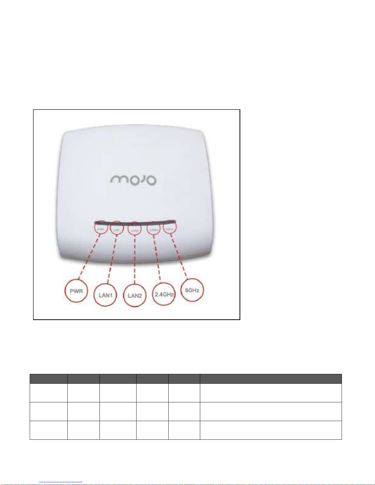
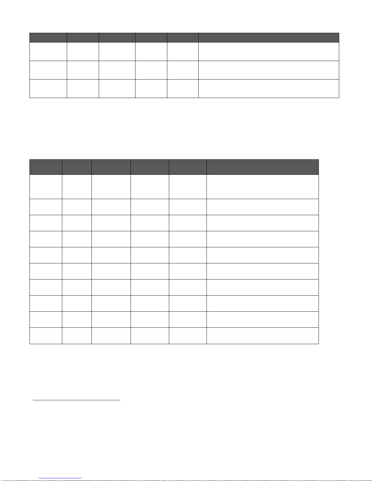
The front panel of the C-75 has 5 LEDs that indicate the working of the device.
Figure 0-1 Front Panel of C-75
The following table indicates the device states based on the LEDs.
Table 0-1 LED Details for C-75 in the AP mode
Page 9
C-75 Installation Guide
9
Power
LAN1
1
LAN2
2.4 GHz
5 GHz
Description
Solid
Orange
Fast
Blink
On/Off
Any
Any
The AP did not receive a valid IP address via the
DHCP.
Solid
Orange
Slow
Blink
On/Off
Any
Any
The AP is unable to connect to the server.
Off
Off
Off
Off
Off
The AP is not powered on or it is in the process
of starting up.
Power
LAN1
1
LAN2
2.4 GHz
5 GHz
Description
Solid
Green
Solid
Green
On/Off
Solid green
Solid
green
The sensor is powered on and is
working normally. The sensor is
connected to the server.
Solid
Green
Solid
Green
On/Off
Solid green
Fast blink
The sensor is performing
troubleshooting on 802.11a/b/g/n.
Solid
Green
Solid
Green
On/Off
Solid green
Slow blink
The sensor is performing intrusion
prevention on 802.11a/n/ac.
Solid
Green
Slow
Blink
On/Off
Slow blink
Off
The sensor upgrade is in progress.
Solid
Orange
Solid
Green
On/Off
Any
Any
The sensor is unable to get Ethernet
link.
Solid
Orange
Fast
Blink
On/Off
Any
Any
The sensor did not receive a valid IP
address via the DHCP.
Solid
Orange
Slow
Blink
On/Off
Any
Any
The sensor is unable to connect to the
server.
Solid
Orange
Any
On/Off
Solid green
Any
There is an error on 802.11a/b/g/n
interfaces.
Solid
Orange
Any
On/Off
Any
Solid
green
The sensor is experiencing a software
error.
Off
Off
Off
Off
Off
The sensor is not powered on or it is in
the process of starting up.
1
Note: LAN2 is ON if the link is up, and is OFF if the link is down. The 2.4 GHz and 5 GHz LEDs blink when there is
activity on the respective radio(s).
Table 0-2. LED Details for C-75 in Sensor mode
Note: LAN2 is ON if the link is up, and is OFF if the link is down. The 2.4 GHz and 5 GHz LEDs blink when there is
activity on the respective radio(s).
If the Ethernet connection for the AP switches to 10/100 Mbps mode while in operation, the Orange LED for
LAN1 starts blinking, while the state of the Green LED for LAN1 is retained. The Orange LED for LAN1 might
continue to blink even if the Ethernet switches back to 10/1000 Mbps mode, and would stop only on rebooting
the device.
Page 10
C-75 Installation Guide
10
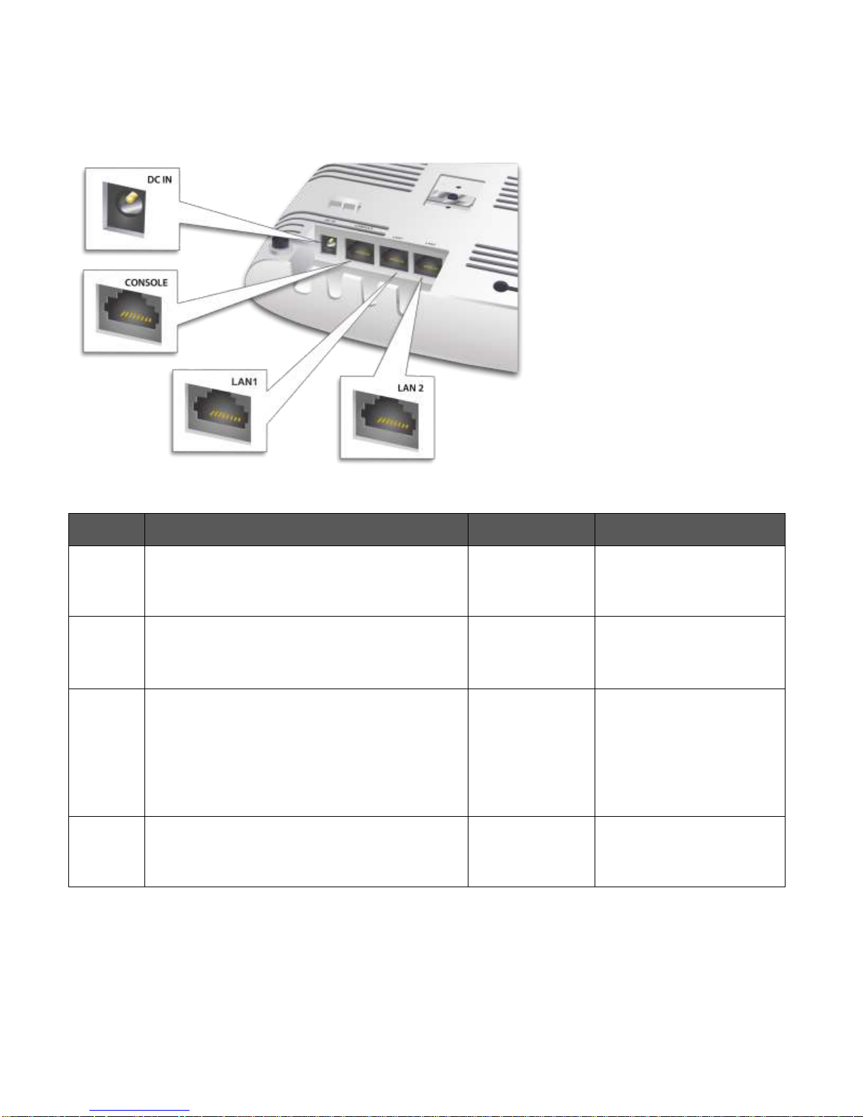
The rear panel of the C-75 has an Ethernet port labelled LAN1, that enables you to connect the device a wired
Port
Description
Connector Type
Speed/Protocol
DC IN
Enables you to connect to and power on device
using 12 V DC power with 2.5 ampere.
--
--
Console
port
(Console)
Enables you to access the AP through a dumb
terminal interface irrespective of the AP state.
RJ45 or DB9
Baud rate to be set to
115200
Ethernet
(LAN1)
Enables you to connect the device to a wired
LAN through a switch or a hub. The device can
then communicate with the server.
This port also provides the power for the device
using the 802.3af standard
RJ45
10/100/1000 Mbps
Ethernet
Power over Ethernet
LAN2
Can be used for advanced AP features.
RJ45
10/100/1000 Mbps
Ethernet
LAN through a switch or a hub and provides the power for the device by using the 802.3af standard.
Figure 0-2 Rear Panel of C-75
Table 0-3 Rear Panel Port Settings for C-75
Page 11
C-75 Installation Guide
11
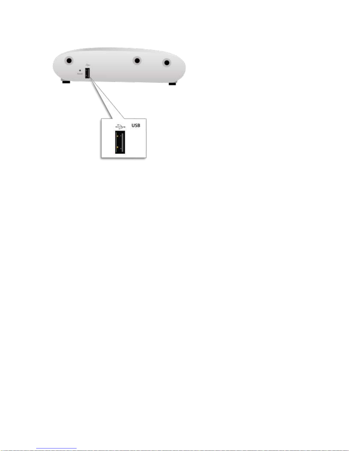
Figure 0-3. Right side of C-75
The Reset Pin Hole and the USB port are on the right side of the device as shown in the figure above. The Reset
Pin Hole resets the C-75 device to factory defaults. To reset the device, power cycle the device (remove the
power cable once and connect it back again) and while plugging the power cable back into the power source,
press and hold down the Reset Pin Hole for 45 seconds until the power, LAN1, 2.4 GHz LEDs go green. Pressing
the Reset Pin Hole while the device is running will not have any effect. When you reset the device, the following
settings are reset:
Config shell password is reset to config.
Server discovery value is erased and changed to the default, wifi-security-server.
All the VLAN configurations are lost.
Device mode is changed to Sensor Only.
If static IP is configured on the device, the IP address is erased and DHCP mode is set. The factory
default IP address of the device is 169.254.11.74.
After reset, all the LEDs will blink once, indicating that the reset is successful, and the system boot sequence is
initiated.
.The USB port connects the C-75 to a USB device. If you are using the cellular activity detection device to detect
cellular activity, you must plug it in to the USB port.
Page 12

C-75 Installation Guide
12
Installing the C-75
When the C-75 functions as a WIPS sensor, it monitors your network and communicates with the server to
guard your corporate network against over-the-air attacks.
Clients can connect to your corporate network in wireless mode through the C-75 AP(s).
The C-75 must be plugged into your corporate network to perform the above-mentioned operation.
From release 7.1 Update 4, the C-75 can also detect cellular activity. You must plug in the cellular activity
detection device into the USB port of the C-75 to detect cellular activity.
Note: In case the C-75 device is already deployed and functional, you need to reboot the device after plugging
in the cellular activity detection device.
As a WIPS sensor, C-75 can be configured in one of the following two modes:
Sensor Mode: This is the default mode. In this mode, the device can be connected to a trunk port
(802.1Q capable) on a switch. The device then monitors the VLANs that are configured on that trunk
port and are chosen by the user. In this mode, an C-75 can monitor up to 16 VLANs. The wireless
interface of the sensor is enabled for WIPS operations.
Network Detector (ND) Mode: This mode needs to be explicitly configured. In this mode, the
device can be connected to a trunk port (802.1Q capable) on a switch. The device then monitors the
VLANS that are configured on that trunk port and are chosen by the user. In this mode, an C-75 can
monitor up to 100 VLANs. The wireless interface of the ND is disabled.
Important: To prevent disconnection or tampering by unauthorized personnel, it is extremely important to
install the device such that it is difficult to unplug the device from the network or from the power outlet.
Zero-Configuration of C-75 as Access Point
Zero-configuration is supported under the following conditions:
The device is in AP mode with background scanning on with no SSID configured.
A DNS entry wifi-security-server is set up on all the DNS servers. This entry should point to the IP
address of the server. By default, the device looks for the DNS entry wifi-security-server.
The device is placed on a subnet that is DHCP enabled.
Important: If the device is placed on a network segment that is separated from the server by a firewall, you
must first open port 3851 for User Datagram Protocol (UDP) and Transport Control Protocol (TCP) bidirectional
traffic on that firewall. This port number is assigned to Mojo Networks. If multiple devices are set up to connect
to multiple servers, zero-configuration is not possible. In this case, you must manually configure the sensors.
Refer to
The steps to install the device with no configuration (zero-configuration) are as follows.
Manually Configuring C-75
1. Mount the device
2. Power on the device.
for further details.
3. Connect the device to the network.
Page 13
C-75 Installation Guide
13
Connecting C-75
This involves mounting the C-75 , powering on the device, and connecting it to the wired network.
Mount C-75
Take a configured C-75, that is, ensure that a static IP is assigned to the device or the settings have been
changed for DHCP. Note the MAC address and the IP address of the device in a safe place before it is installed
in a hard-to-reach location. The MAC address of the device is printed on a label at the bottom of the product.
Recommended: You should label the devices using MAC addresses or at least your own convention. For
example, use serial numbers, so that you can easily identify the devices.
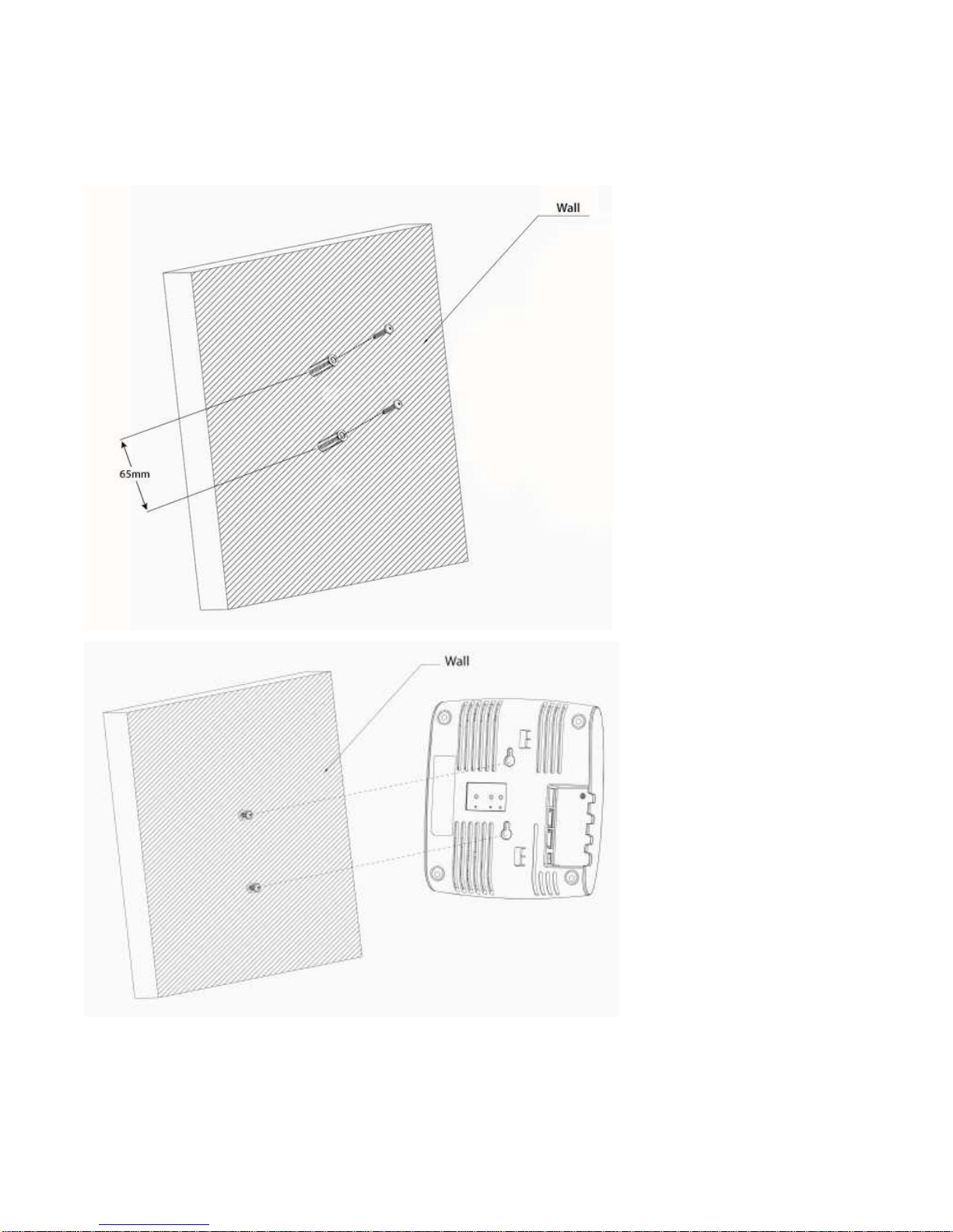
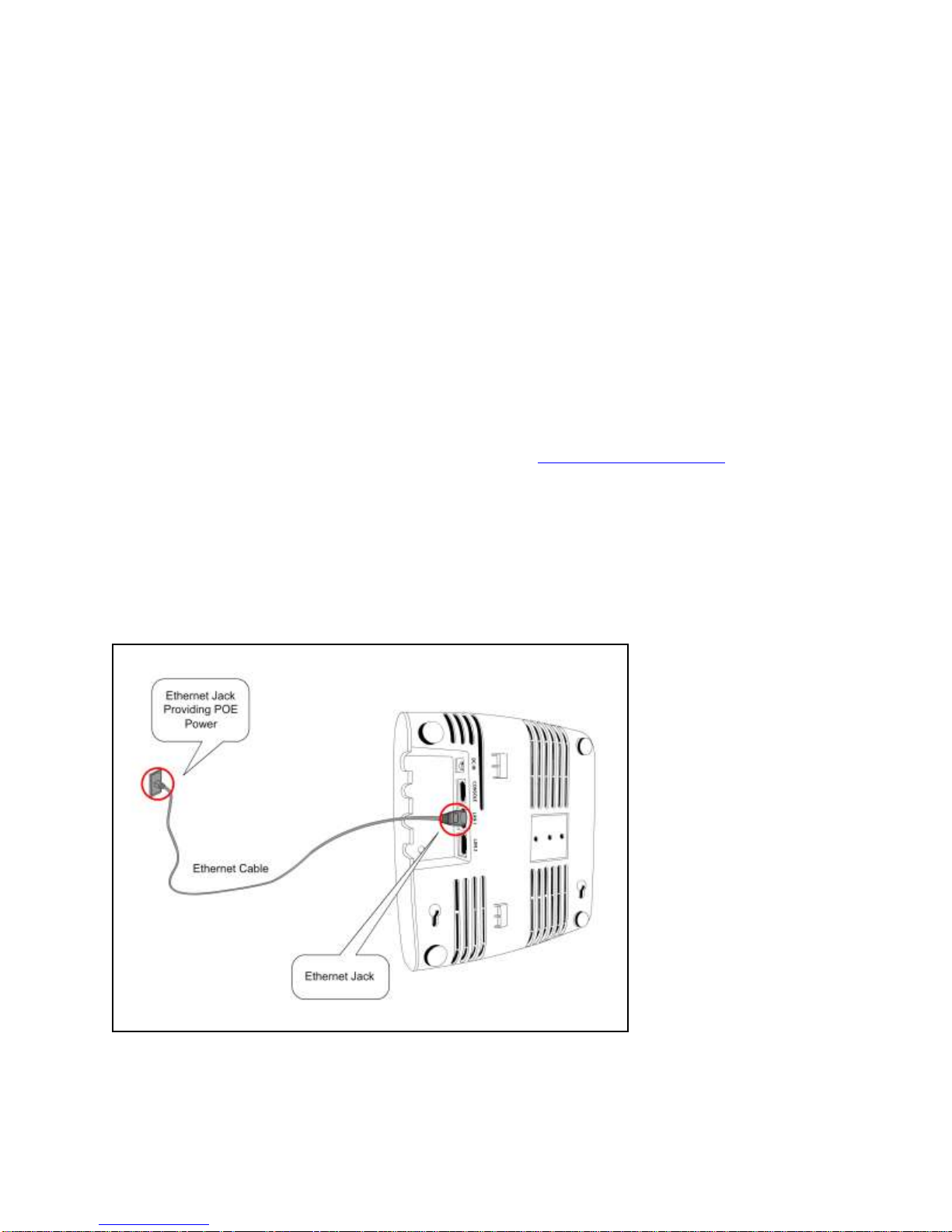
Wall/ Ceiling Mounting
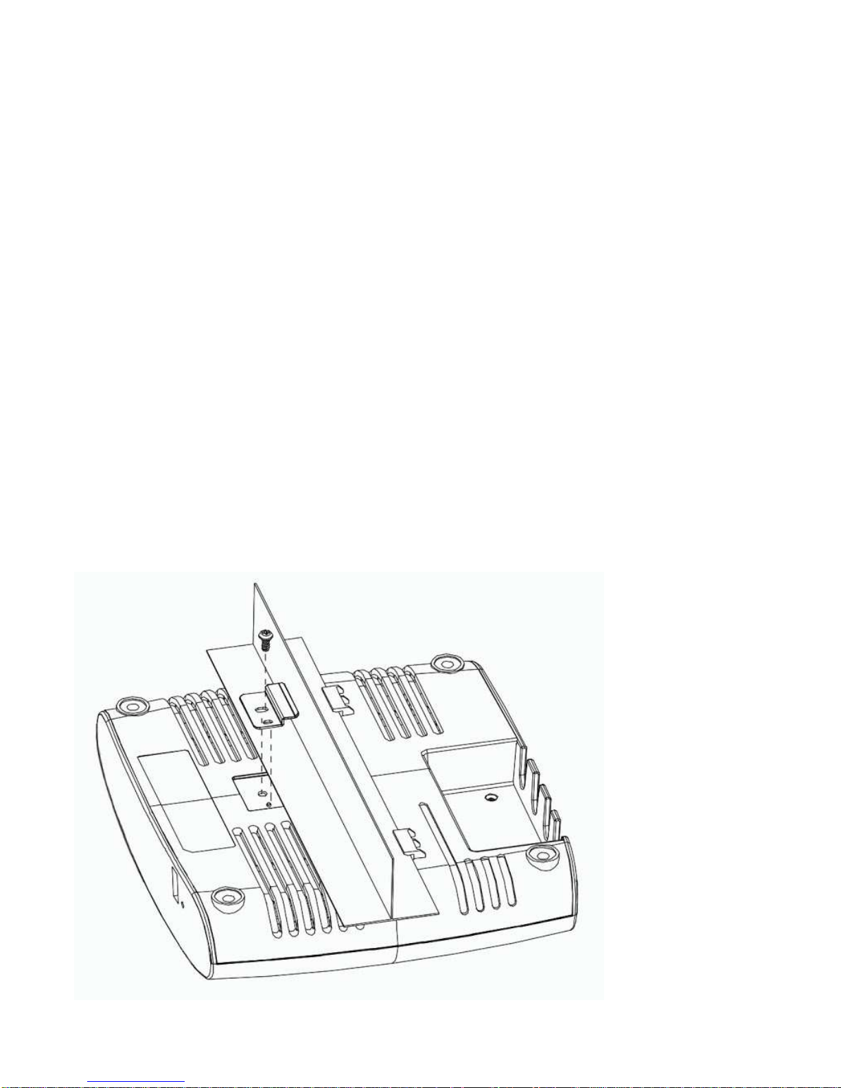
Use the mounting bracket to install the C-75 on the ceiling. To mount the device:
1. Attach the mounting bracket to the wall or ceiling by using the mounting hardware kit.
2. Insert the provided short screws into the bottom cover of the C-75 device.
3. Leave enough of the screws exposed to ensure that the unit can be attached to the mounting
bracket.
4. If extra space is required, use the provided spacers and long screws from the T-Rail mounting
hardware kit to increase the space between the unit and the mounting bracket.
Figure 0-1 Ceiling Mounting
Page 14
C-75 Installation Guide
14
Figure 0-2 Wall Mounting
Page 15
C-75 Installation Guide
15
Power on C-75
A C-75 device can be powered on by 802.3af Class 0 Power Over Ethernet (PoE) of Nominal input voltage 48V
DC. You can connect the device to the network using PoE or a power adapter.
Connect C-75 to the Network
To connect C-75 to the network, perform the following steps.
1. Ensure that a DHCP server is already available on the network to enable network configuration of
the C-75.
2. Add the DNS entry wifi-security-server on all DNS servers. This entry should point to the IP address
of the server.
3. Ensure that DHCP is running on the subnet to which the device will be connected.
Important: If DHCP is not enabled on a subnet, the device cannot connect to that subnet with zeroconfiguration. If the DNS entry is not present on the DNS servers or you do not have the DHCP server running
on the subnet, you must manually configure the device. Refer to
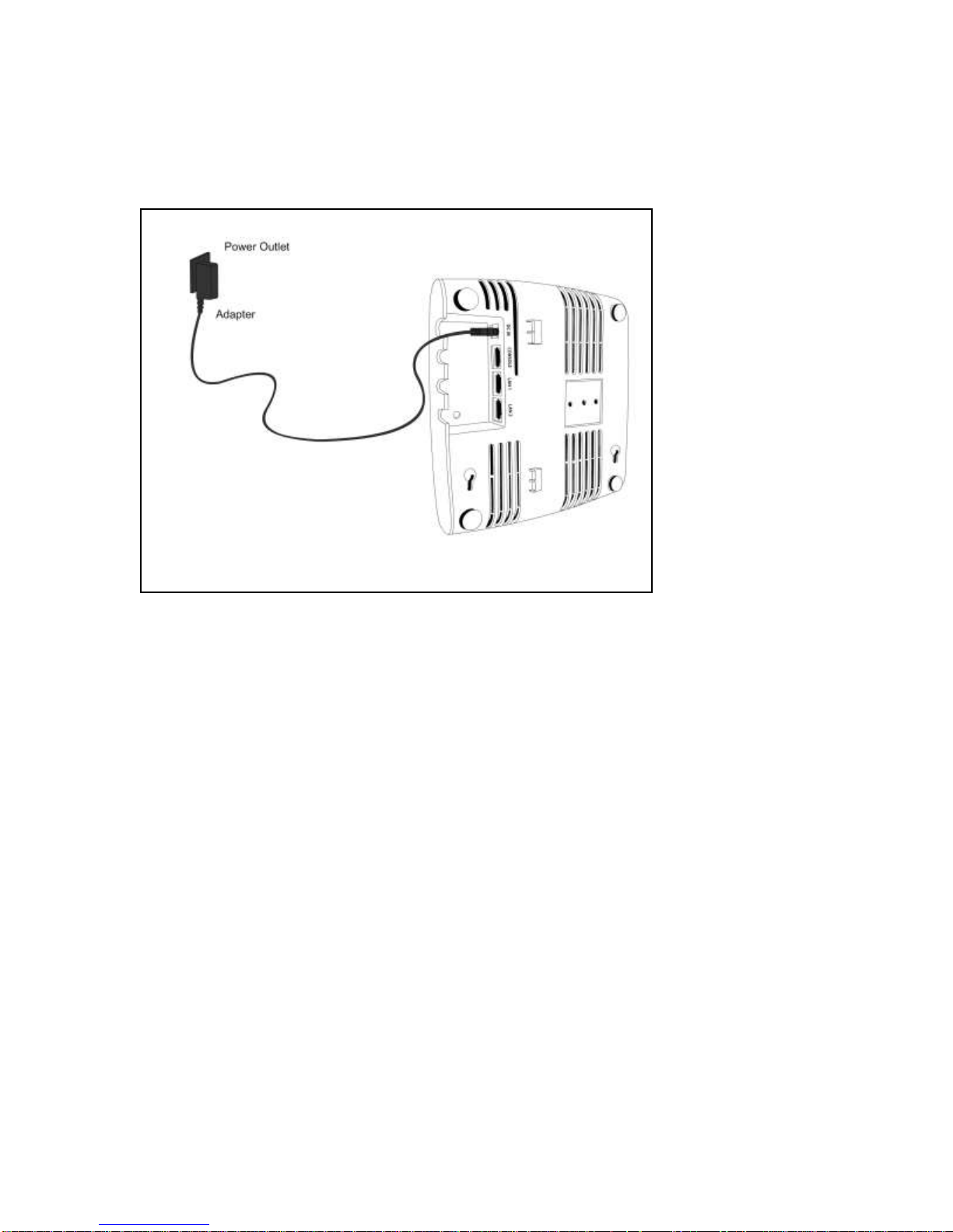
Using C-75 with PoE
To power on and connect C-75 to the network using PoE, do the following:
Manually Configuring C-75
for further details.
1. Connect one end of the network interface cable to the Ethernet port at the rear of the C-75.
2. Connect the other end of the network interface cable to the Ethernet jack that provides PoE power.
Figure 0-3. Power Up and Connect C-75 using PoE
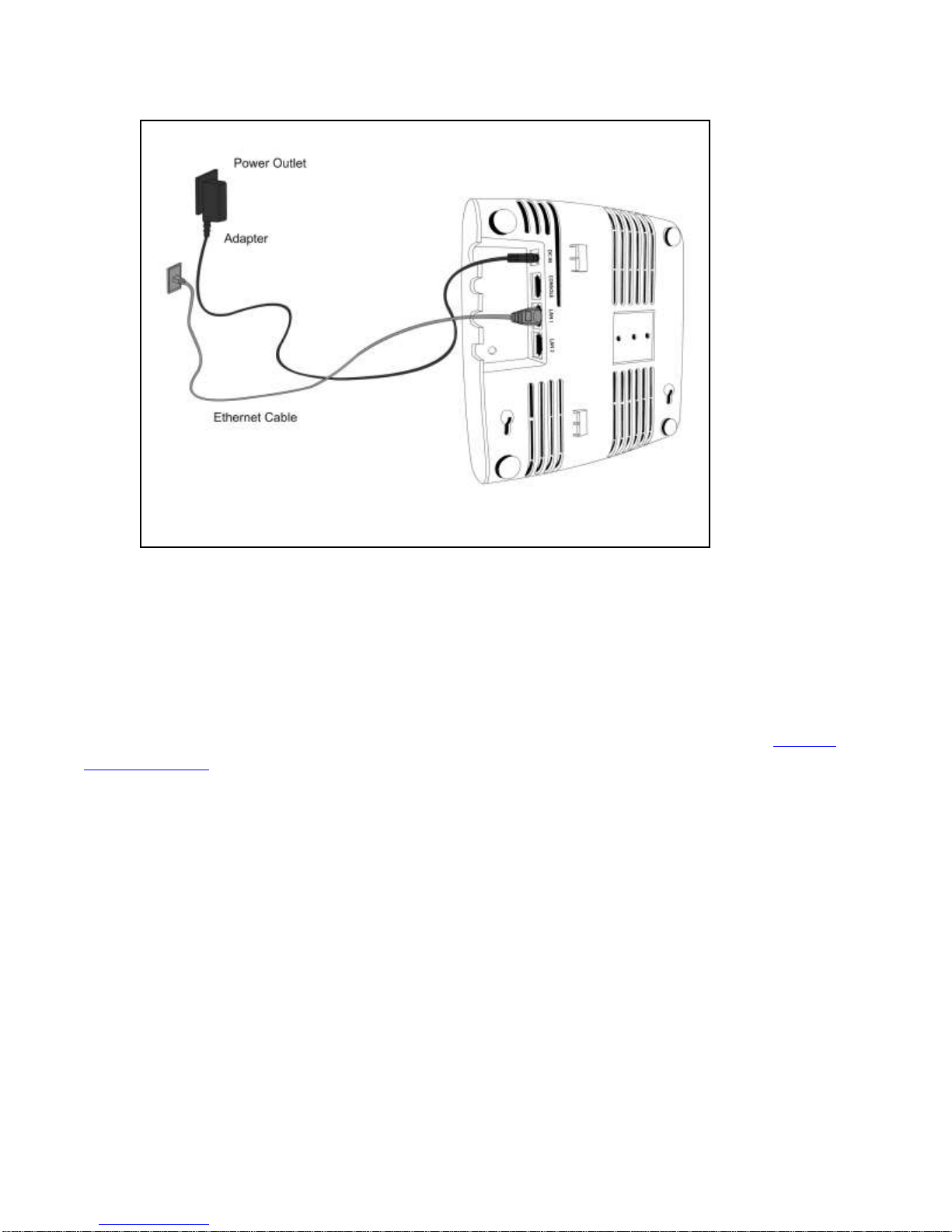
Using C-75 with power adapter
To power up the device, perform the following steps:
1. Plug the power cable into the DC power receptacle at the rear of the device.
Page 16
C-75 Installation Guide
16
2. Plug the other end of the power cable into an 110V~240V 50/60 Hz AC power source.
Wait until the device is ready. Refer to the respective LED details table based on the configured device
mode.
Figure 0-4. Power Up C-75
To connect C-75 to the network, perform the following steps:
1. Ensure that a DHCP server is available on the network to provide network configuration to the C-75.
2. Connect one end of the network interface cable to the Ethernet port at the rear of the C-75.
3. Connect the other end of the network interface cable to an Ethernet jack on the desired subnet.
Wait until the device is ready (approx. 10 mins).
Page 17
C-75 Installation Guide
17
Figure 0-5. Connect C-75 to network
4. Check the status LEDs on the device. If all LEDs glow green, then the device is operational and
connected to the server.
5. Log on to the server through SSH and run the get sensor list command.
You would see a list of all Mojo devices that are recognized by the server. Mojo One users can go to the
Devices tab in Mojo Wireless Manager and check whether the device is visible under the Devices tab.
The device is configured and ready to go operational.
Note: If the zero configuration is not successful, the device must be configured manually. Refer to
Configuring C-75
for details.
Manually
Page 18

Manually Configuring C-75
Important: If the installation in the
previous chapter
was successful, stop! You do not need to configure the
device manually.
Introduction
Manual configuration of C-75 is typically required in the following cases:
Devices cannot connect to the server through zero-configuration.
Device needs to be configured in the ND mode.
Sensor Only (SO) devices cannot connect to the server through zero-configuration. The DNS entry
for the server has been changed to an entry other than wifi-security-server or a DNS server is not
present in the network. This is applicable for multi-server installations.
Device is placed on a subnet that is not DHCP enabled.
Configuring AP through Config Shell
The Config Shell supports a pre-defined set of commands used to configure the C-75 device. Log in to the
device console using the SSH shell.
The steps to configure the device manually through the SSH shell are as follows:
1. Log in and change the default password
2. Set Server Discovery
3. Set Sensor Mode
4. Configure Network Settings
Log in and Change the Default Password
Log in to the Config Shell using the user name config and password config. Change the default password
using the passwd command. You can change the device password using device templates. Refer to
Template
Recommended
section under the
:
Although not mandatory, as a best practice we recommend that you change the default
Administration Tab
chapter, in the
Users Guide
for more details.
Device
password.
Set Server Discovery
The next step is to set the server discovery information. The following are the types of server discovery:
Server IP based discovery (preferred)
Service Location Protocol (SLP) based discovery (if wifi-security-server service has been
configured)
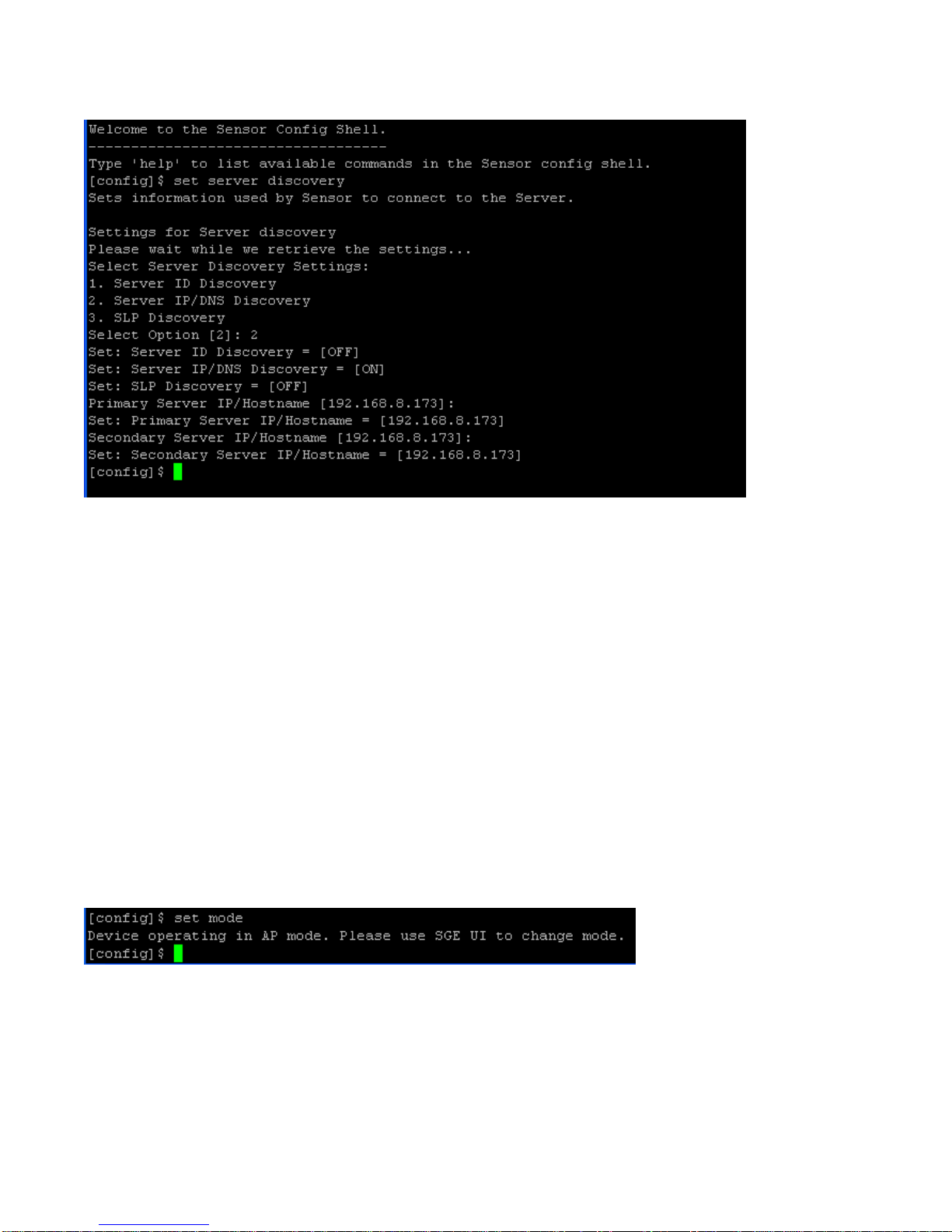
Use the set server discovery command to point the AP device to the correct server.
C-75 Installation Guide
18
Page 19
C-75 Installation Guide
19
Figure 0-1 The set server discovery Command
Note: If IP address/ host name based discovery is being used and more than one server is present on the
network, then you must enter the IP address of the appropriate server.
Set Sensor Mode
The next step is to set the mode of the sensor. There are two possible modes:
Sensor Mode: This is the default mode. In this mode, the device can be connected to a trunk port
(802.1Q capable) on a switch. The device then monitors multiple VLANs that are configured on that
trunk port and are chosen by the user. The wireless interface of the sensor is enabled. In this mode, a C75 can monitor up to 16 VLANs.
ND Mode: This mode needs to be explicitly configured. In this mode, the device can be connected
to a trunk port (802.1Q capable) on a switch. It then monitors multiple VLANs that are configured on
that trunk port and are chosen by the user. The wireless interface of the ND is disabled. In this mode, a
C-75 functioning as a WIPS sensor can detect and monitor up to 100 VLANs.
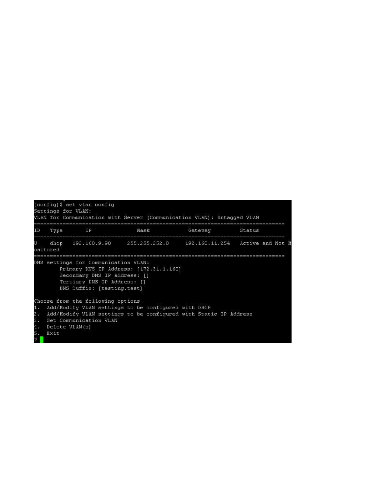
Use the set mode command to set the device mode for C-75.
Figure 0-2 The set mode Command for C-75
Page 20
Configure Network Settings
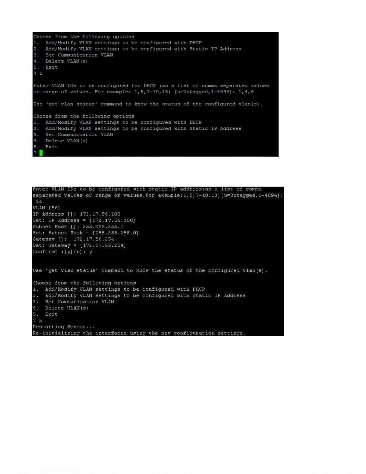
After the mode is set, you have to configure the network settings. For the Network Detector/Sensor mode, use
the set vlan config command to configure the IP addresses on the ND.
With the set vlan config command, you can do the following.
Add /modify VLAN settings to be configured with DHCP.
Add/modify VLAN settings to be configured with a static IP address.
Set communication VLAN.
To configure VLANs, do the following.
1. Type the set vlan config command to configure all the VLANs.
2. Choose option 1 to configure VLANs for DHCP and option 2 to configure VLANs with static IP
address.
The device will restart / reboot after the VLAN configuration.
To configure VLANs with DHCP, you must provide comma-separated VLAN IDs.
See the figure below for configuring VLAN with DHCP.
C-75 Installation Guide
20
Page 21
C-75 Installation Guide
21
To configure VLANs with static IP address, you must provide the IP address, the subnet mask and the gateway.
See the figure below for configuring VLAN with a static IP address.
To configure/ change the Communication VLAN, do the following
1. Type the set vlan config command.
2. Choose option 3 from the menu that appears.
Configure a static IP address in absence of a DHCP server
1. Connect a crossover cable from the computer to the Ethernet port of C-75.
2. Configure the LAN IP address on the computer in the subnet 192.168.1.0/24.
3. SSH to IP address: 192.168.1.245 (factory default)
4. Log in to the CLI of the device using default credentials.
Page 22

C-75 Installation Guide
22
5. Configure server discovery on the device.
6. Configure a static IP address on the device. For example: Untagged VLAN 192.168.2.x/24.
After completing this step you will lose the SSH connection.
7. Configure the LAN IP address in the range of 192.168.2.x/24 and again SSH to the address assigned
in step 6.
8. Check the configuration settings.
9. Remove the crossover connection to the computer and connect the Ethernet port to the local
switch.
Configure IPv6 settings
C-75 is IPv6 capable. Use the set ipv6 config command to configure advanced options such as DHCP settings,
auto negotiation, and manual configuration.
Enable auto negotiation to discover IP address automatically.
Enable DHCP settings to obtain addressing as well as more information, such as the DNS address
from DHCP server in the network.
Enable manual configuration to provide manual IPv6 address as well as IPv6 default gateway.
How to configure Communication Key or Passphrase
To configure the communication key or passphrase kindly refer to Appendix A: AP-Server Mutual
Authentication for further details.
Page 23
C-75 Installation Guide
23
C-75 Config Shell Commands
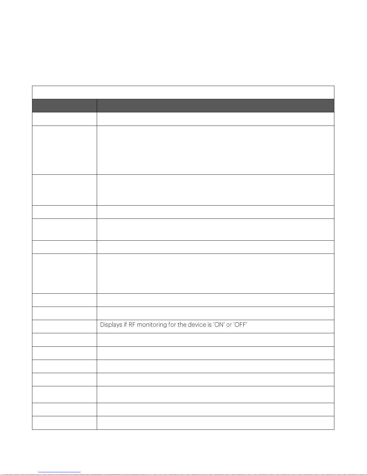
get Commands
Command
Description
get ap
Displays all the currently visible APs
get channel util
Displays the current channel utilization in %, non-Wi-Fi interference in %, and noise
floor values in dBm when device is in AP mode. The radio must have at least one
active virtual AP to get the channel utilization statistics. You can choose to fetch the
current utilization or to auto-read the channel utilization statistics every 5 seconds.
Press Ctrl+C to stop auto-read.
get device config
Creates a tar bundle containing the current device configuration, which the user can
download. The tar bundle can be stored for future reference. You can download
individual configuration files instead of the entire tar bundle.
get interface
Displays network interface speed and mode
get ip config
(deprecated)
Displays the IP information
get log
Displays the log information as it is created
get logs
Displays the hyperlink to the tar file (.tar.gz) containing all logs for the device. Copy
paste this hyperlink in a web browser to download the tar file. This command can
also be used to retrieve kernel panic logs. The kernel panic logs are created when the
AP crashes and they can be found in the panic_logs directory of the tar file.
get log config
Displays the configuration of the logger
get mode
Displays the mode in which the device is currently configured
get rf
get serial num
Displays the board number
get server discovery
Displays the server discovery/setting information
get status
Displays the current running status of all the components
get version
Displays the version and build information of all the components
get vlan config
Displays VLAN configuration. Both static and dynamic information is displayed.
get vlan id
Displays listing of all VLANs that can be detected by ND.
get vlan status
Displays status of VLANs that are configured for monitoring by ND.
The following tables detail the C-75 config shell commands.
Table 0-1 get Commands
Page 24
C-75 Installation Guide
24
set Commands
Command
Description
set erase
Sets the erase character to ^H.
set interface
Sets network interface properties such as auto negotiation, speed, and duplex
settings.
set ip config
Runs through the current VLAN and IP config wizard.
set server discovery
Sets the server discovery information.
set vlan config
Configures list of VLANs and their network settings to be monitored by ND.
set ipv6 config
Sets IPv6 network settings.
get vlan connectivity
Pings the specified VLAN other than the communication VLAN.
get model
Displays the AP model.
get antenna
Displays antenna configuration (internal/ external).
get route
Displays IP routing table entries.
get client logs
Gets client connection logs as it happens.
get wired trace
Performs packet capture on Ethernet interface(eth0) upto file size 5MB.
get ap status
Displays wireless profiles and associated clients.
get presence
notification
parameters
Displays the value of the presence notification parameters, that is, RSSI value in dbm,
time interval in seconds, and IP address or host name of the presence notification
server.
get admctl stats
Displays statistical information related to admission control of both the radios and a
list of the connected and admitted clients.
Table 0-2. set Commands
Page 25
C-75 Installation Guide
25
set communication
key
Sets the AP-server shared secret. You must enter a hexadecimal value, of length 32,
as the shared secret. It can be used instead of the set communication passphrase
command. Use this command if you are comfortable working with hexadecimals.
set communication
key default
Sets the communication key to its default value.
set communication
passphrase
Sets the AP-server shared secret. You must enter a character string, of length
between 10 and 127, as the shared secret. The string is internally converted to
hexadecimal format. It can be used instead of the set communication key command.
set presence
notification
parameters
Sets the presence notification parameters. The parameters for presence notification
are the RSSI value in dbm, IP address/hostname of the presence notification server
and time interval in seconds. The RSSI value can range between -127 and 0 dbm. The
time interval can range between 0 and 14400 seconds.
Page 26
C-75 Installation Guide
26
Table 0-3. Miscellaneous commands
Other Commands
Command
Description
exit
Exits the config shell session
help
Displays help for all commands
help set
help get
help other
passwd
Changes the config shell password
ping <Hostname/IP
address>
Pings a host.
Usage: ping <IP_address/host_name>
For example, ping 192.168.1.246
ping6 <IPv6 address
or hostname>
Pings an IPv6 host
Usage: ping6 <IPv6_address/host_name>
reboot
Reboots the AP
restart
Restarts the AP application
reset factory
Resets the AP . The factory default IP address of the device is
192.168.1.245.
upgrade
Upgrades the AP manually from a given IP address
presence notification
enable
Enables the presence notification feature.
presence notification
disable
Disables the presence notification feature.
Page 27
Symptoms
Diagnosis
Solution
Wi-Fi: any
Ethernet: fast blink
Power: solid orange
The device did not
receive a valid IP
address via the
DHCP.
Ensure that the DHCP server is on and available on the
VLAN/subnet to which the device is connected. If the
device still fails to get a valid IP address, you can reboot it to
see if the problem is resolved.
The Ethernet cable is
loose. The device is
probably
disconnected from
the network.
Ensure that the Ethernet cable is connected.
Wi-Fi: any
Ethernet: slow blink
Power: solid orange
Unable to connect to
the server
Ensure that the server is running and is reachable from the
network to which the device is attached. If there is a firewall
or a router with ACLs enabled between the device and the
server, ensure that the traffic is allowed on UDP port 3851.
Use the server IP-based discovery and ensure that you have
correctly entered the DNS name, wifi-security-server, on
the DNS server. Also, ensure that the DNS server IP
addresses are either correctly configured on the, or are
provided by the DHCP server.
It is also possible that the AP is unable to connect to the
server because it has failed to authenticate with the server.
In this case, an 'Authentication failed for ' event is raised on
the server. Refer to the event for recommended action.
C-75 Troubleshooting
Following are the troubleshooting guidelines for C-75.
C-75 Installation Guide
27
Page 28

C-75 Installation Guide
28
Appendix A: Sensor-Server Mutual Authentication
Note
: Although the server is backward compatible, that is, older version sensors can connect to a newer
version server, this is not recommended.
Note
: After the shared secret (communication key) is changed on the server, all sensors connected to the
server will automatically be set up to use the new communication key. Sensors that are not connected to the
server at this time must be manually set up with the same communication key to enable communication with
this server.
The Sensor-server communication begins with a mutual authentication step in which the sensor and server
authenticate each other using a shared secret. The sensor-server communication takes place only if this
authentication succeeds.
After the authentication succeeds, a session key is generated. All communication between the sensor and
server from this point on is encrypted using the session key.
The sensor and server are shipped with the same default value of the shared secret. The CLI commands are
provided on both server and sensor for changing the shared secret.
 Loading...