

Page 1
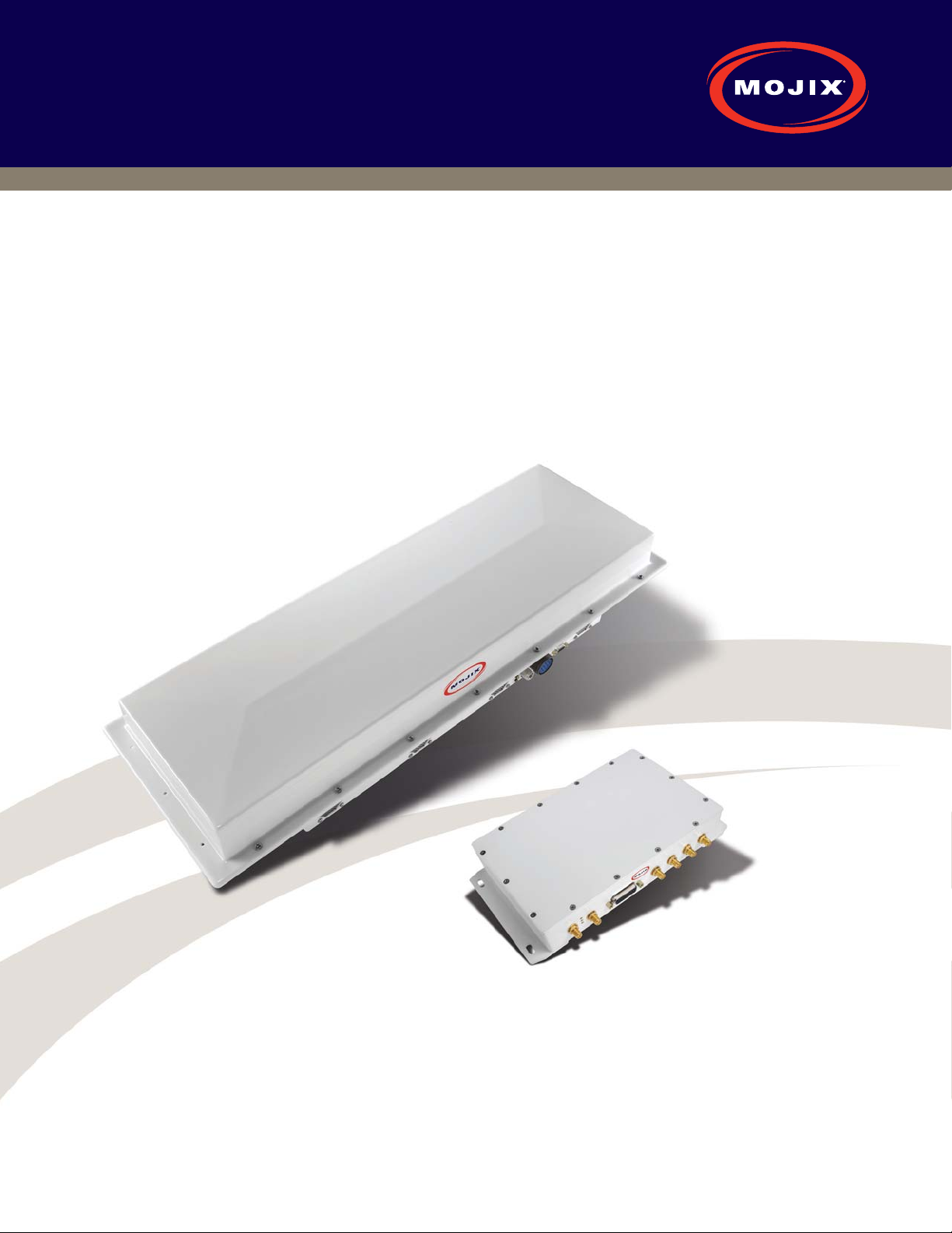
Mojix STAR™ 1000
System User Manual
January 2009
Mojix Incorporated
11075 Santa Monica Blvd., Suite 350
Los Angeles, CA 90025
Web: www.mojix.com
Tel: (877) 886-6549
E-mail: [email protected]
Page 2

Legal Notices
Copyright 2009 Mojix, Inc. All Rights Reserved.
All content contained within this document, including text, graphics, logos, icons, images, and other materials, is
the exclusive property of Mojix or its content suppliers and is protected by U.S. and international copyright laws. The
compilation (meaning the collection, arrangement, and assembly) of all content within this document is the exclusive
property of Mojix and is also protected by U.S. and international copyright laws. The content within this document may
be used as a resource. Any other use, including the reproduction, modification, distribution, transmission, republication,
display, or performance, of the content on this website is strictly prohibited.
MOJIX, Mojix STAR, Mojix eNode, Mojix eGroup, and the Mojix logo are trademarks or registered trademarks of Mojix.
All other trademarks mentioned in this document are the property of their respective owners. The trademarks and logos
contained in this document may not be used without the prior written consent of Mojix or their respective owners.
Portions, features and/or functionality of Mojix’s products are protected under Mojix patents, as well as patents pending.
This User Manual is provided as a reference for persons who are properly trained and qualified to install and/or
operate Mojix’s RFID products. Whereas Mojix makes every effort to ensure the accuracy and currency of its technical
documentation, Mojix cannot be responsible for errors that occur in this User Manual or for changes to Mojix’s
products that might render information in this Manual obsolete. For information regarding Mojix technical training, visit
Mojix’s website (www.Mojix.com) or contact Mojix at [email protected].
Improper handling or use of RF equipment can result in damage to property or injury to personnel.
FCC Compliance
This equipment has been tested and found to comply with the limits for Class A digital device, pursuant to Part 15
of the FCC Rules. Any change or modification to this product voids the user’s authority to operate per FCC Part 15
Subpart A. Section 15.21 regulations.
B
2
Page 3

Mojix® STAR 1000 System User Manual
LEGAL NOTICES ..........................................................................2
INTRODUCTION ..........................................................................4
1. SYSTEM COMPONENTS ................................................................6
1.1. MOJIX ENODES: DISTRIBUTED TRANSMITTERS .........................................6
1.2. STAR RECEIVER: CENTRALIZED READ AND CONTROL POINT ..............................6
1.3. STAR INTERROGATION SPACES ......................................................7
1.4. MASTER CONTROLLER .............................................................7
1.5. SYSTEM TOPOLOGY ...............................................................7
2. STAR RECEIVER INSTALLATION ..........................................................9
2.1. STAR RECEIVER POSITIONING .......................................................9
2.2. STAR RECEIVER INSTALLATION ......................................................10
2.3. STAR RECEIVER CABLING ..........................................................16
3. ENODE INSTALLATION ................................................................17
3.1. ENODE POSITIONING ..............................................................17
3.2. ENODE CABLING .................................................................17
3.3. 4-PORT ENODE CABLING ...........................................................18
4. EMUX INSTALLATION .................................................................19
4.1. ABOUT INSERTION LOSS ...........................................................19
4.2. EMUX SPECIFICATIONS ............................................................19
5. MASTER CONTROLLER INSTALLATION ...................................................21
5.1. MASTER CONTROLLER (MCON) HARDWARE REQUIREMENTS ............................21
5.2. MCON DEPLOYMENT OVERVIEW ....................................................21
6. SYSTEM CONFIGURATION .............................................................22
6.1. NETWORK SETUP .................................................................22
6.2. GRAPHICAL USER INTERFACE. . . . . . . . . . . . . . . . . . . . . . . . . . . . . . . . . . . . . . . . . . . . . . . . . . . . . . . 24
6.3. EMUX CALIBRATION ..............................................................28
APPENDIX A: LOCATION CONFIGURATION GUIDELINES ........................................29
APPENDIX B: DEPLOYMENT EXAMPLE ......................................................32
APPENDIX C: ADVANCED TROUBLESHOOTING ................................................34
APPENDIX D: ENGINEERING INTERFACE - MOJO ..............................................37
APPENDIX E: MANUAL EMUX CALIBRATION ..................................................41
APPENDIX F: GLOSSARY ..................................................................43
APPENDIX G: INDEX ......................................................................46
3
Page 4
Introduction
In 2004, a team of advanced signal processing and deep space communications scientists and engineers led
by Dr. Ramin Sadr formed Mojix
communications to the commercial wireless infrastructure industry. The result is a commercial passive RFID reader
system with capabilities orders of magnitude beyond previous RFID reader offerings, and a new generation of RFID
system technology that eliminates the economic and technical barriers to large-scale, high-volume RFID deployment
to deliver on the full promise of RFID.
®
Inc with the vision of applying the technical breakthroughs in deep space
The Mojix family of products can be configured to
transmit and receive across the UHF band and can
operate in both the near and far fields which make
it possible for a single system to read tags at the
pallet, carton or item level. The UHF or ISM band as
it is commonly referred to, is partially allocated for
public use and is heavily utilized by many different
devices and applications which make operating in
this spectrum especially challenging.
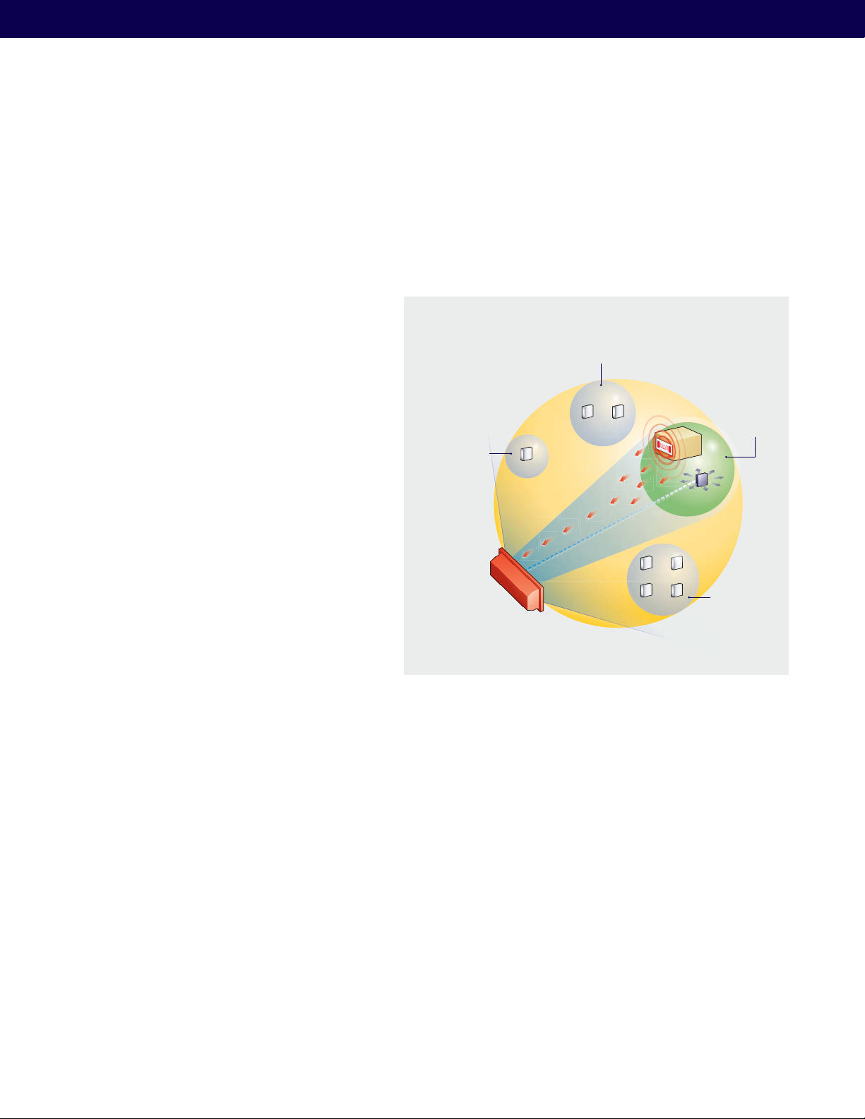
One Mojix STAR
covers interrogation
spaces for all eNodes
within a 3-D coverage
area, managing single
or multiple business
processes.
Interrogation
Space
Retail Sales
Floor
Interrogation Space
Retail
Backroom
Active
Interrogation
Space
The STAR Receiver is powered directly by its power
supply and in turn powers each Mojix eNode
™
.
Warehouse
Each eNode is connected to the STAR by coaxial
cable and receives supply voltage, command and
control signals, and baseband RF over this medium.
The STAR Receiver is typically connected to the
enterprise via the LAN or an optional WLAN.
STAR
Receiver
Distribution
Center
Interrogation
Space
An eNode, as depicted in Figure 1, creates and is
associated with a single interrogation space, which
is individually addressed and controlled by the STAR
Figure 1: Mojix STAR System Overview
Receiver. eNodes are physically positioned according
to business process needs to provide optimal performance in exciting Gen2 RFID tags. The STAR Receiver is ordinarily
positioned with a vantage point to all eNodes in the system — this can be line of sight (LOS) or non-line of sight (NLOS)
but always within the rated Rx range.
This document is intended to assist developers integrate Mojix systems. Please also see Mojix STAR 1000 User Guide
for assistance deploying Mojix systems.
4
Page 5

Mojix STAR System Specifications
Mojix® STAR 1000 System User Manual
MOJIX STAR Receiver Array Technical Specifications
Operating Frequency
Tag Protocols
Dimensions STAR
reader
Weight STAR reader
Power Supply
Power consumption
Dimension Power
supply
Weight Power supply
External RF Connector
External I/O
Temperature
Humidity
Indicators
Compliance Regulatory: FCC Part15
Firmware Upgrade Remotely upgradeable
Application User
Interface
IP Addressing – STAR
reader
Network Interface Ethernet, Base-T, RJ-45 Interface
UHF Band, 902-928 MHz, FHSS
EPC Gen2
AIA (30 3/8)in L x (10 7/8)in Wx (4 3/4)
in H
77 cm L x 27.6 cm W x 12 cm H
12.6 lb 5.7 Kg
220/110 VAC
200 Watts operational, 100 Watts in
standby
Power supply 11in L x 18in W x (2 5/8)
in H
28 cm L x 45.7 cm W x 6.6 cm H
11.4 lb 5.2 Kg
N type Female
DB-15 (8 Dry relay contacts 4in / 4 out)
Operating: -25° to +50° C (+32° to
+122° F)
Storage: -40° to +70° C (-4° to +158° F)
5-95% non-condensing
LED's for power, standby and transmit
EPC Class 1 Gen2
HTTP
Static
Mojix STAR Master Controller Technical Specifications
Network Interface
Operating System
Logical interface
IP Addressing
Ethernet 10/100/1000 Base-T
Linux
TCP/IP Interface
HTTP
Application Programming Interface
Static and Dynamic
Mojix eNode Technical Specification
Operating Frequency
Dimensions eNode
Weight eNode
Humidity
Compliance
Indicators LED’s for Power, Calibration and Transmit
External I/O TWO TNC connectors for RF & one DB-9
Transmit power Per FCC Part 15
Power supply Powered through coaxial cable (24 volts
eNode Addressing Static at Factory
Warranty 1 year from date of shipment
Extended Warranty Available
UHF Band, 902-928 MHz, FHSS
12in L x 12in W x 2.5in H ;
30.5 cm L x 30.5 cm Wx 6.35 cm H
4.8 lb 2.1 Kg
5-95% non-condensing
Regulatory: FCC Part15
EPC Class 1 Gen 2
for external sensors
Transmit power: 1 Watt (30 dBm)
Maximum
Antenna: 6 dBi integrated patch antenna
DC)
Mojix eNode Multiplexer Specifications
Parameter Specification
Signals Present at Input/Output
RF Frequency Range
RF Signal Level (Max.)
Input Connector TNC
Output Connector 4 TNC’s
Input Impedance 50 Ohm
DC Input 24 V
DC Input Connector Male Power Jack
950110126000000896
DC, RF and Control
902-928 MHz
+20 dBm (output)
950110126000001107
5
Page 6
1. System Components
A Mojix STAR system is a single network element at the enterprise edge. Based on Mojix’s innovative distributed
architecture, a single system consists of one or more STAR receivers managing up to 512 low-cost Mojix eNode
transmitters. Mojix eNodes provide energy to all passive RFID tags within their specified interrogation spaces, while
the centralized, high-sensitivity Mojix STAR receiver reads the resulting tag signals from across the system’s potentially
vast coverage area - up to 250,000 sq. feet.
1.1. Mojix eNodes: Distributed Transmitters
Each Mojix eNode excites all passive RFID tags within its designated interrogation space and can be fixed, wireless or
handheld, and can be deployed as needed to shape discrete, overlapping or contiguous interrogation spaces, as well as
to create virtual fences for securing tagged items.
Mojix eNodes are reliable, autonomously operated RF repeaters designed to excite all EPC UHF Gen2 RFID tags within
their designated interrogation spaces with an excite range – depending on the tag being used - of over 30 feet and a
coverage area of more than 2,500 square feet. Up to 512 eNodes are controlled by a single Mojix STAR Receiver, able
to manage a mixed population of single and multi-port eNodes, as well as sensors in support of numerous concurrent
business processes.
1.2. STAR Receiver: Centralized Read and Control point
The STAR Receiver functions as a single point of data collection, provisioning, command and control, and integration
with enterprise systems. With the ability to detect extremely faint signals and free from conventional RFID’s lineof-sight restrictions, the STAR receiver works in concert with its satellite eNodes to support one or many business
processes across the entire coverage. The STAR-1000 Receiver contains a 1 x 4 array assembly, and digital and RF
processing assemblies. The STAR Receiver utilizes classical, fully active, phased array antennas for enabling the
visibility into the space dimension. The smart array approach adopted by Mojix is based fully on digital processing
techniques, thereby providing very high resolution for estimation of direction of arrival of the signal of interest (SOI),
enabling the system to provide accurate location information on the tag position in the three dimensional Euclidean
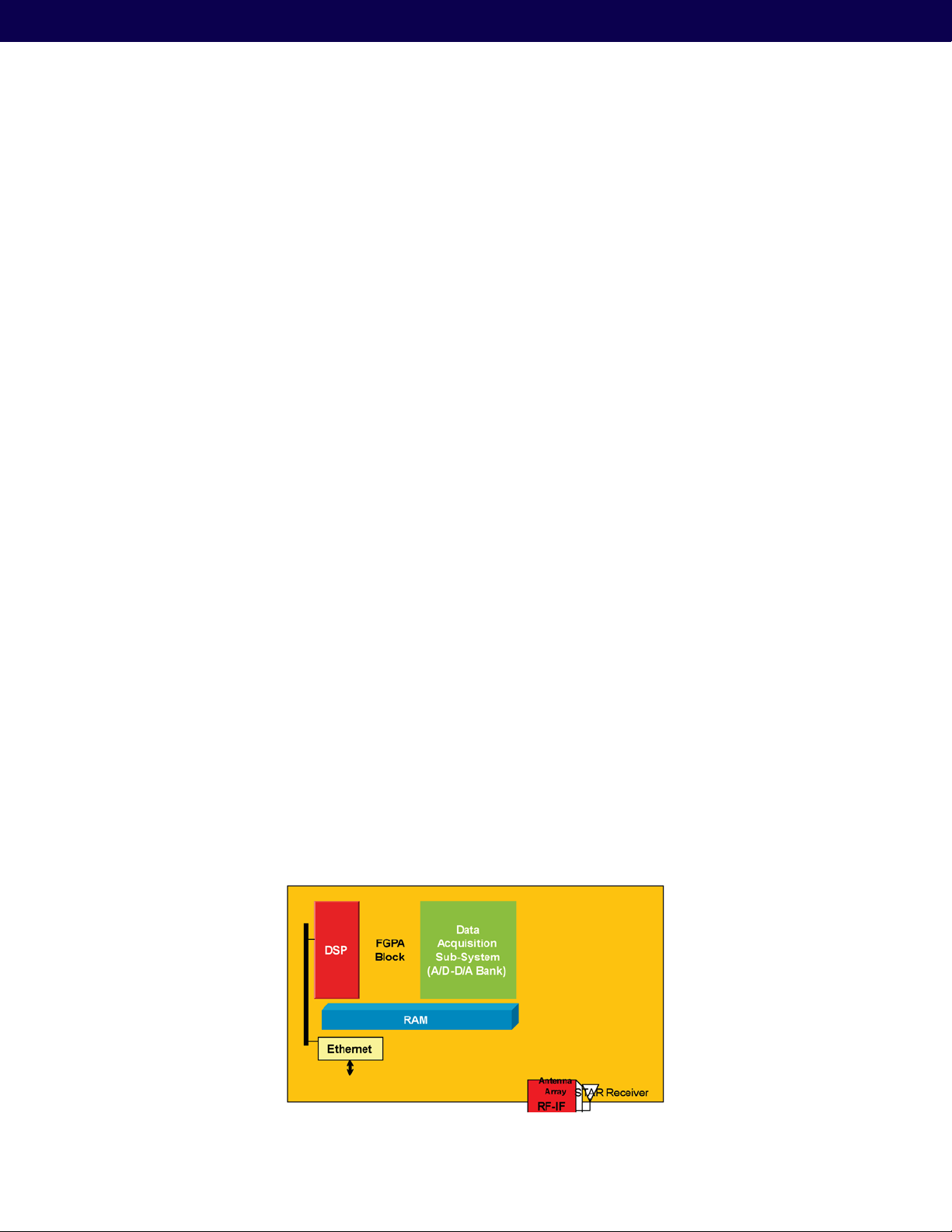
space. The STAR Receiver hardware overview is shown in the following figure:
a) RF / IF sub system
b) Digital Subsystem – including ADC, DAC
c) Digital Signal Processing subsystem
d) Ethernet interface
6
Figure 2: STAR Receiver Hardware overview
Page 7

Mojix® STAR 1000 System User Manual
1.3. STAR interrogation spaces
Fixed or mobile, STAR interrogation spaces are business process-specific and can be optimized for tag density or
coverage. Each individually controlled interrogation space is created by the deployment of single or multiple eNodes
and is dynamically sized by the STAR system, which controls each node’s power output.
1.4. Master Controller
The STAR-1000 STAR Receiver signal processing platform is linked to an edge appliance called a Master Controller
(MCON), and communicates via a standard Ethernet 10BaseT (RJ45)-connector. The MCON can drive an arbitrary
number of STAR-1000 systems and includes interfaces to the enterprise middleware. In a larger enterprise deployment,
multiple STAR domains would exist in various locations and would require one or more controllers, which are generic,
Linux based edge appliances.
1.5. System Topology
Figure 3 illustrates the components of the STAR system topology. These items are as follows:
a) STAR Receiver
b) STAR Power Supply
c) eNodes – single or 4-port
d) Master Controller
e) LAN
Power
Supply
WAN
Internet
LAN
Receiver
Master
Controller
Tx/Power/Control
Array
Tx/Power/Control
Corporate
Internet
Figure 3: STAR System Topology
eNodes
Figure 4 illustrates a total system topology with cabling, showing the following elements:
eNodes
Sensor/Alarms
1. STAR Receiver
2. eNodes
3. eNodes with DC-Block & 50 Ohm Termination
4. eMux
5. Sensor
6. MCON
7
Page 8
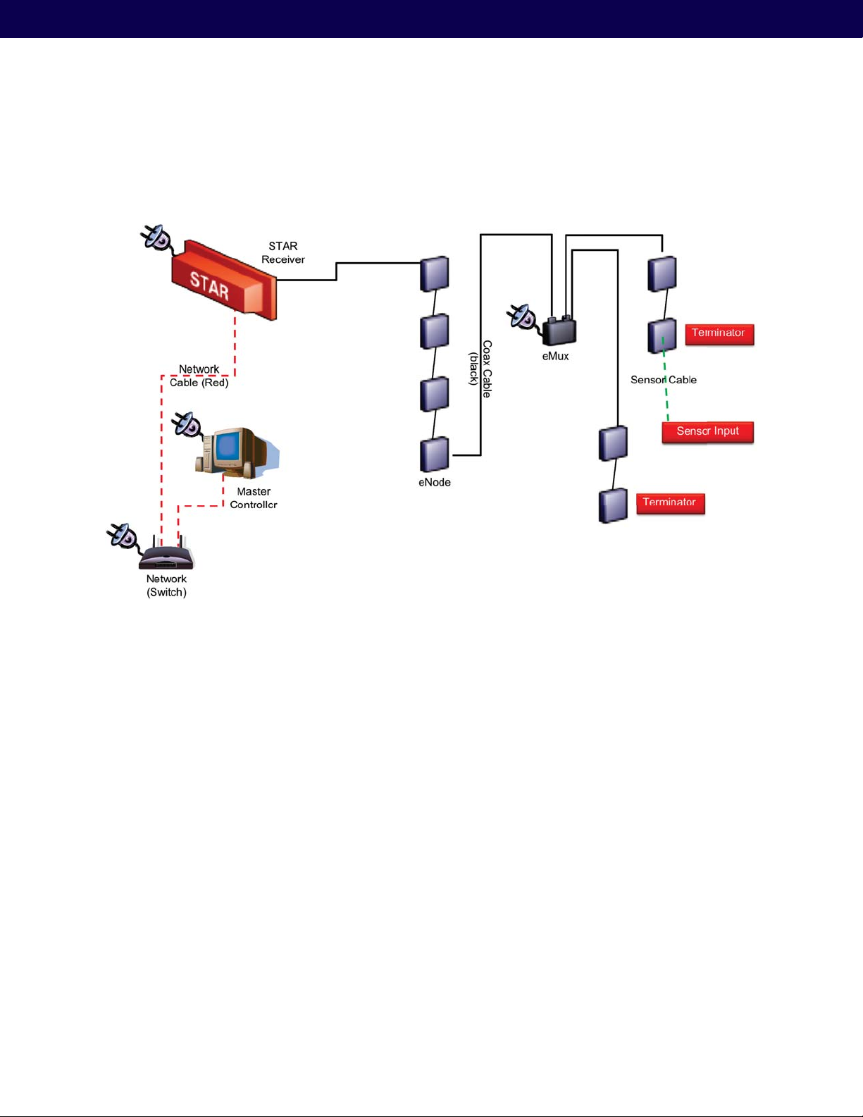
From the figure, the STAR RF output is cabled to the four (4) eNodes in a daisy chain configuration, followed by an
eMux. In this example only two out of the four available eMux outputs are use to further connect to two strings of
daisy chained eNodes. Lastly, there are the two eNodes at the end of each chain with a 50 Ohm termination.
Figure 4: Cabling Overview – STAR, eNode and eMux
In what follows the Mojix STAR system will described, including installation, and operational guidelines. Also described
will include the user interfaces, as well as hardware configuration procedures.
The required equipment for installation of the STAR System includes:
1 Master Controller (MCON)
2 STAR Receiver
3 STAR Power Supply
4 Power supply cable - Length: 20 ft Max.
5 eNodes
6 eMux (optional)
7 eMux Power Supply (optional)
8 Coaxial Cable – Connecting the STAR to an eNode or eMux
9 Coaxial Cables – Connecting eNodes to eNodes or eMuxes
10 STAR Receiver Mounting Hardware (post mount kit)
11 eNode Mounting Hardware
12 eMux Mounting Hardware (optional)
13 Ethernet Cable
8
Page 9
Mojix® STAR 1000 System User Manual
2. STAR Receiver Installation
2.1. STAR Receiver Positioning
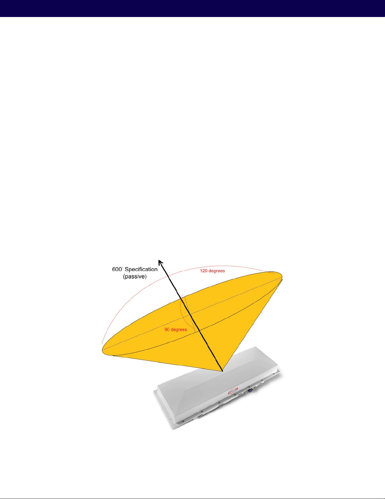
Figure 5 illustrates the STAR Receiver and the respective view angle. The following list indicates the key environmental
considerations for installing the unit.
a) Building Height
b) Obstructions such as racking, shelves, walls, and staged product
c) AC power drops
d) Network drops
e) Targeted interrogation spaces
f) Orientation and pointing of the unit with respect to the interrogation spaces
The view angle of the STAR receive array is:
120 degrees (+/- 60 deg) in the X direction (horizontal) †
90 degrees (+/- 45 deg) in the Y direction (vertical) †
The read range — i.e. the furthest point that the interrogation space can from the reader is approximately 600 feet.
Figure 5: STAR Positioning Guidelines
9
Page 10

2.2. STAR Receiver Installation
The STAR is mechanically designed for post and wall mounting. Figure 6, illustrates the assembly drawing for installing
the unit on a post (i.e. installation kit is provided)
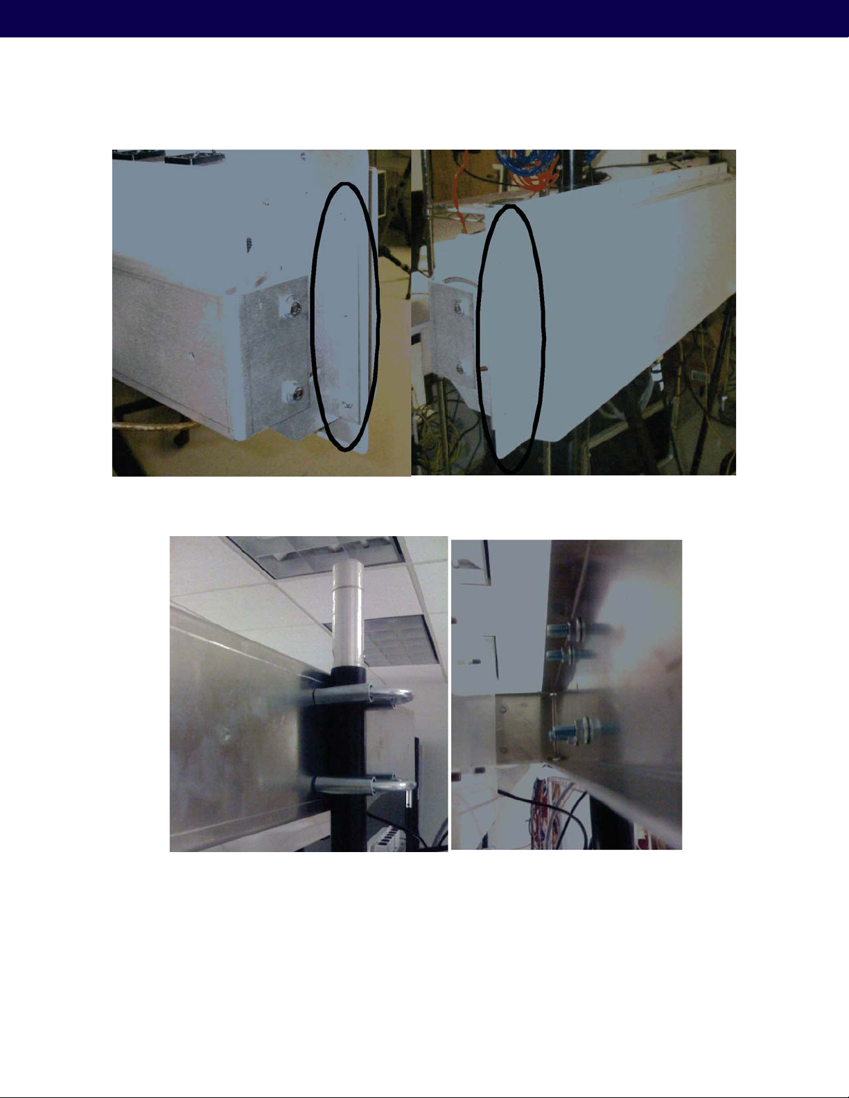
From the figure the mounting bracket is installed directly on the STAR Receiver back plate. Figure 6, Figure 7, Figure 8,
and Figure 9 show the required hardware, installation steps and final assembled and installed unit. Table 2 and Table 3
details the required hardware, which is included with shipping.
Installation instructions:
1. Product installation shall be conducted by a qualified installer. The appropriate local engineer or architect shall
be consulted to ensure the wall and/or pole mount is capable of safely supporting up to 4 times the weight of
the product.
2. Should the customer select to mount the STAR unit to a flat surface (e.g. wall), holes are provided in the main
mounting bracket to accommodate a family of hardware (customer supplied).
3. When mounting STAR unit to a flat surface, a minimum of 4 fasteners are recommended, though the exact
type is a function of the wall material and construction. Best industry practice is recommended.
a. For example: toggle bolts or Molly bolts would be the first choice on hollow walls. Lead lag shields would
be recommended on solid (cast) concrete or brick. Nails are not recommended, but could be used only if
the wood material of the wall was at least 1.5” thick.
4. The recommended mounting procedure would be as provided before for mounting to a mast, pole, pipe or
post. When securing the unit to a flat surface, it is recommended that the two end brackets be mounted to the
STAR Receiver.
5. The main bracket is mounted and (leveled if desired) to the wall using one of the techniques described
above. The STAR Receiver is then secured to the main bracket using the 1/4-20 hex bolts, washers and nuts
as illustrated in the same drawing as for mast mounting, though it is recommended that the pivot bolts be
secured first, and then the arc positioning hardware secured.
Tightening hardware, be it machine screws in Molly and Toggle bolts, Drywall Screws, 1/4-20 screws or the U-Bolts
is to be done with the appropriate tool: screwdriver or wrench. The hardware is to be “tight” to best construction
standards. For those that may have a torque wrench, the following values are recommended:
Screws: nominal 3 ft-lb +/- .5
1/4-20 hardware: 6 ft-lb +/- .5
U-Bolts: 20 ft-lb +/- 1
10
Page 11

Mojix® STAR 1000 System User Manual
Figure 6: STAR Receiver Post Mount Installation kit
4 303-0004-000 Washer, Split Lock, .25” MCM 91102A750 7
8 303-0003-000 Washer, Flat, .25” MCM 90108A413 6
4 302-0015-000 Hex Nut, .25–20 MCM 91841A029 5
2 302-0012-000 U-Bolt Assembly, 2” MCM 3042T31 4
4 301-0015-000 Screw, Hex Head Cap, .25–20X.75 MCM 92240A540 3
1 309-0002-000 Mounting Support 2
2 309-0001-000 Mounting Bracket 1
QTY REQD
CAGE
CODE
PART OR IDENTIFYING NO. NOMENCLATURE OR DESCRIPTION
MATERIAL /
SPECIFICATION
PARTS LIST
Table 1: Parts List for STAR Receiver Pole-Mount Installation Kit
ITEM
NO.
11
Page 12
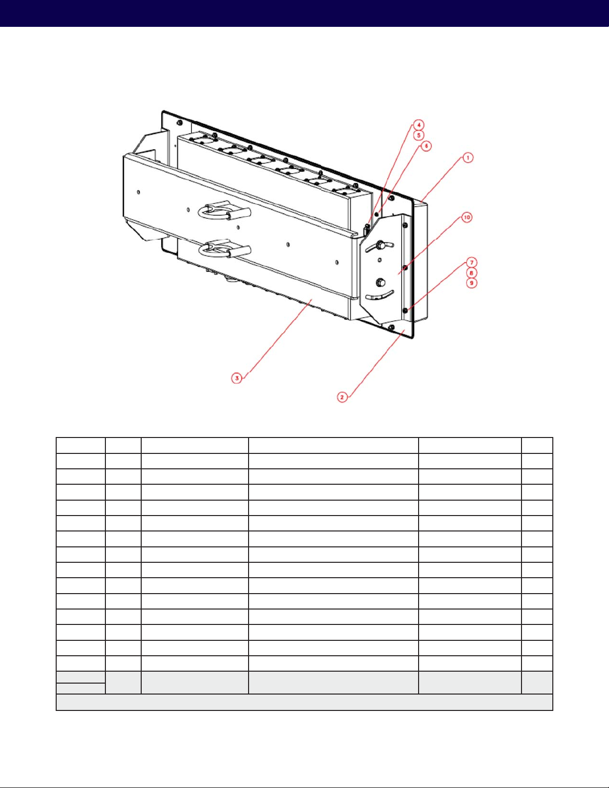
Figure 7: Pole Mount Installation, showing STAR Receiver and bracket
4 303-0004-000 Washer, Split Lock, .25” MCM 91102A750 15
4 303-0003-000 Washer, Flat, .25” MCM 90108A413 14
4 302-0015-000 Hex Nut, .25–20 MCM 91841A029 13
1 TBD Vesa Mount Assembly 12
2 TBD Production Handle 11
1 800-0102-000 Bracket Assembly 10
20 800-0001-000 Screw, Phillips Pan Head, 6-32X.625 9
40 300-0005-000 Flat Washer, #6 8
20 300-0003-000 Lock Washer, #6 7
6 300-0004-000 Screw, Phillips Pan Head, 6-32X0.25 6
4 301-0002-000 Female Screw Locks, 4-40X.312 AMP 205818-2 5
4 303-0002-000 Lock Washer, #4 4
1 302-0009-000 Rear Cover Assembly 3
1 800-0105-000 AIA / AFA Board Subassembly 2
1 301-0020-000 Radome 1
QTY REQD
CAGE
CODE
PART OR IDENTIFYING NO. NOMENCLATURE OR DESCRIPTION
MATERIAL /
SPECIFICATION
PARTS LIST
Table 2: STAR Receiver Pole Mount and Reader Parts List
ITEM
NO.
12
Page 13
Mojix® STAR 1000 System User Manual
Figure 8: STAR Receiver Mount
Figure 9: STAR Receiver Pole Mount
2.2.1. STAR power supply installation
Recommended installation of the power supply is “platform mounting”, where the unit is secured flat on a platform,
co-located within “20 feet” from the STAR Receiver. Power supply installation guide is as follows.
13
Page 14
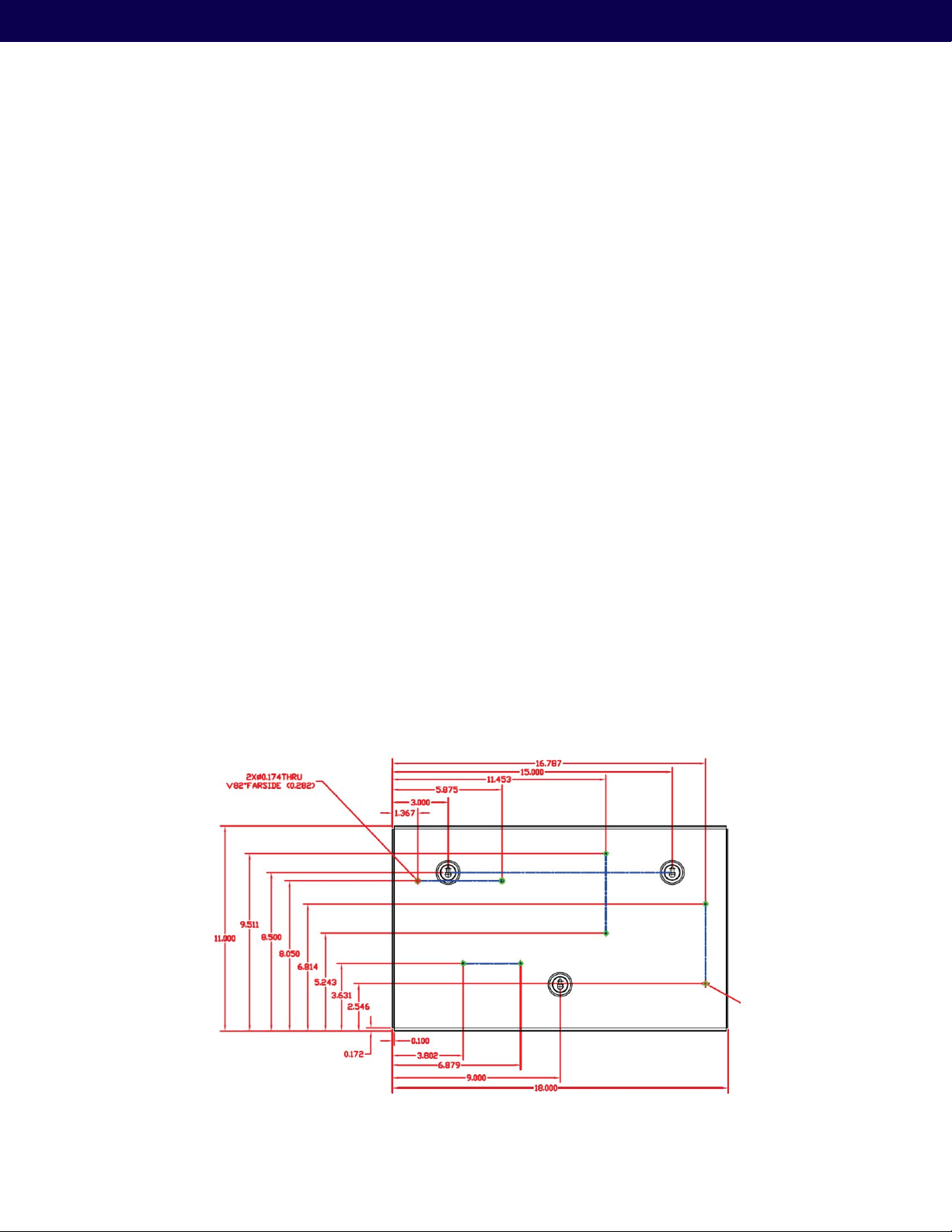
2.2.1.1. Wall Mount Power Supply
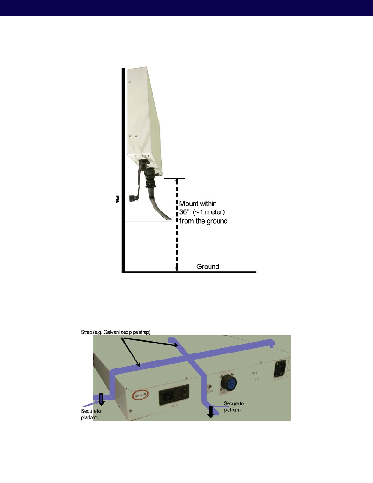
Figure 10 shows the power supply mechanical drawing and key holes to be used when mounting it on the wall. Note:
As shown in Figure 11, when mounted on the wall –unit shall be installed within “3 feet” from the ground, and †
within 20 feet from the STAR Receiver
The keyholes are designed for either †
#6 Drywall (bugle head) or #6 wood screws if the unit is being fastened to a wooden surface. –
For a solid wood mount, box nails can be used, providing the head diameter is more than .28” and less than .30” –
in diameter and the shank of the nail is at least 2” long.
If the unit is being fastened to a metal surface that is at least .1875” thick, 6-32 pan head machine screws may –
be used.
If the unit is being fastened to drywall/plaster, 1/8 Molly or Toggle bolts must be used. –
The recommended mounting procedure is:
1. To use drywall mounts (“Molly Bolts” are preferred) for that purpose (these, or toggle bolts, offer a pull-down
force more than 4X the industry-standard, and are highly recommended in areas prone to seismic activity).
2. Bugle-head #6 Drywall screws (coarse thread) are acceptable, if all 3 tie down points are used, offering an
industry-standard of a pull-down strength of at least 4X the weight of the unit.
3. If the walls are of at least 1/2” wood (plywood, for example), nails can be used.
In addition, the cable must be properly dressed and supported. The cables, both AC and DC, are to drop down from the
power supply with a drip or service loop. They are to be supported at least once within 18” of the unit, and according
to best industry practice (and NEC) at intervals of no more than 36”. Cables can be run in conduit, providing (a) the
conduit is not hanging on the cables, (b) the service loop exists, and (c) there is at least one support/tie-down on the
cables between conduit and power supply.
14
Figure 10: Power Supply — showing key holes for wall mounting
Page 15
Mojix® STAR 1000 System User Manual
Figure 11: Power Supply – showing wall mount
2.2.1.2. Platform Mount
When mounting the power supply on a platform, it shall be strapped and secured, as shown in Figure 12. Additionally,
ensure that the connectors are facing out for easy access.
Figure 12: Power supply platform mount
15
Page 16
2.3. STAR Receiver cabling
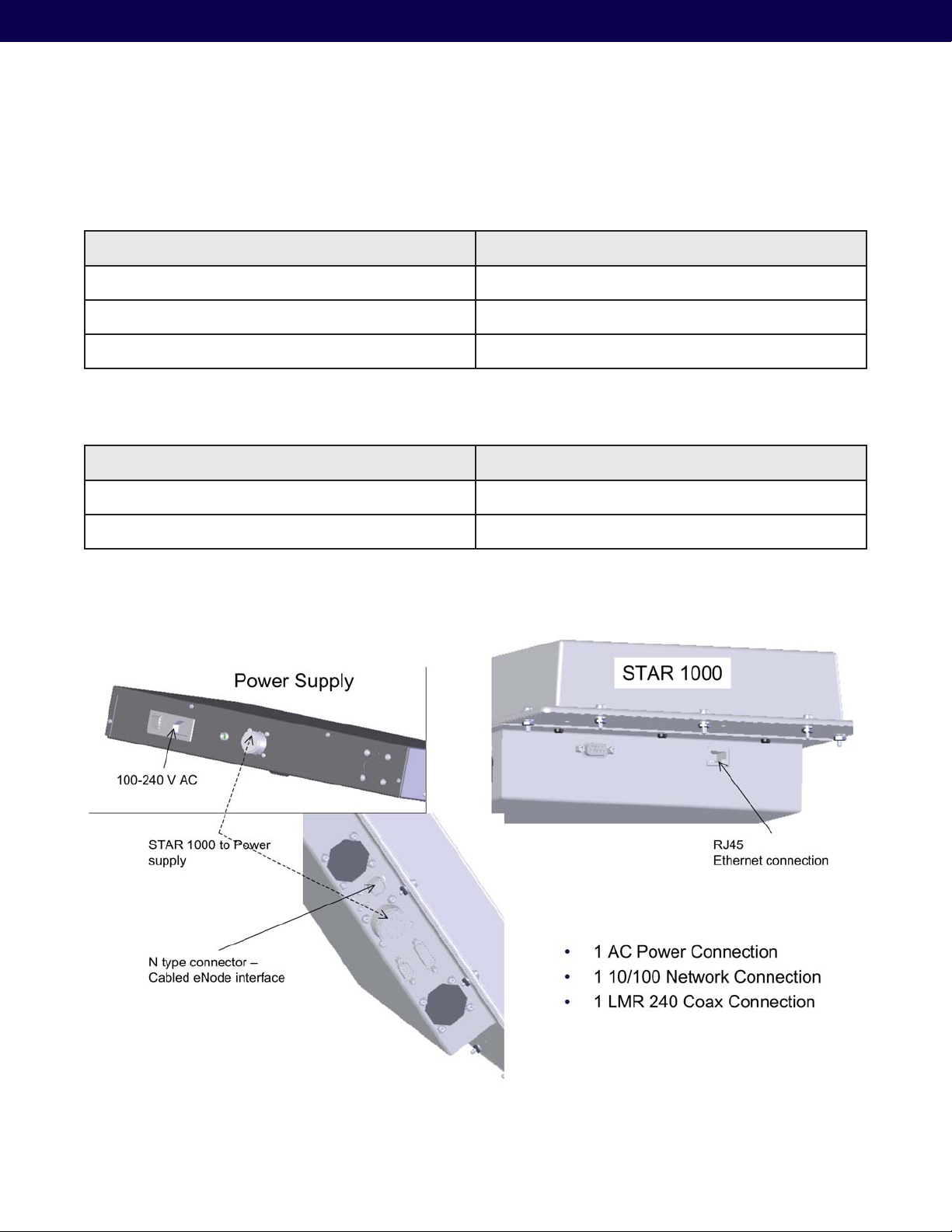
The cabling specification for the STAR unit is shown in Figure 13, and details are described in Table 3 and Table 4.
Receiver Specifications Comment
Power supply connector Input from STAR power supply
Ethernet connector RJ-45
TX RF coaxial connector – to eNode or eMux N-Type connector — see Section 2.2 for details
Table 3: STAR Receiver cabling specifications
Power Supply Specifications Comment
Power supply connector Circular DIN Connector
AC connector 100-240V AC
Table 4: Star power supply cabling specifications
16
Figure 13: STAR Receiver and power supply – showing connections
Page 17
3. eNode Installation
3.1. eNode Positioning
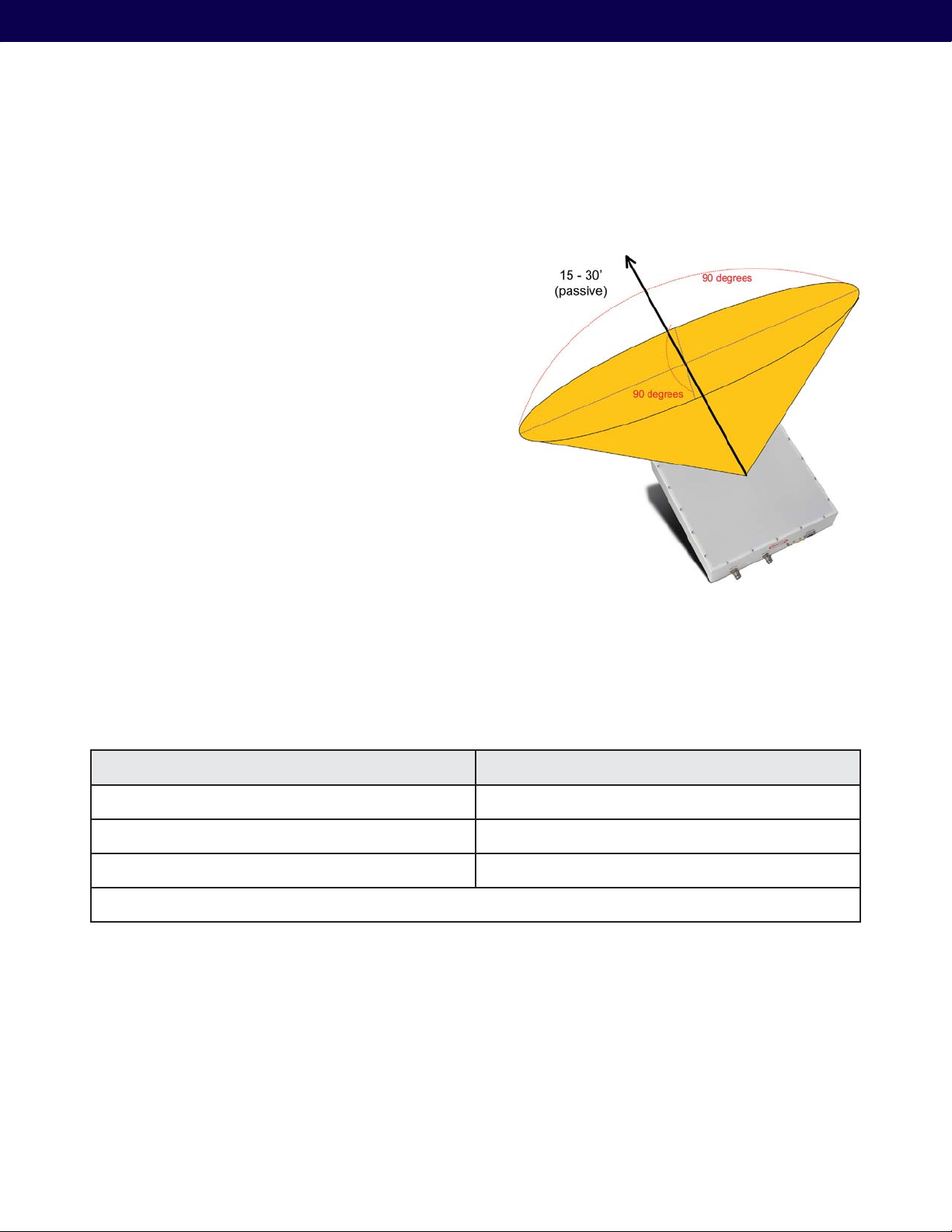
Figure 14 illustrates the eNode, and its corresponding view
angle. Following are the key considerations to review when
installing eNodes:
a) Distance between the eNode and tags in the
interrogation space
b) Size of the interrogation space
c) Obstructions – between eNode and interrogation
space
d) Orientation and pointing of the eNode with respect
to the interrogation space
Mojix® STAR 1000 System User Manual
The view angle of the eNode is in compliance with FCC
& ETSI specification. The excitation range of the tags is
highly dependent on tag manufacturer, tag placement, tag
orientation, and the content of the tagged material. Typical
tags receive sufficient power to turn on at greater than 30
feet (9.1 meters) of the eNode in free space, meaning that
the tag is held in mid-air and not attached to any material.
3.2. eNode Cabling
Figure 15 illustrates the Single-Port eNode, showing the RF and I/O connectors. Connector specification is provided in
the following table.
eNode Specification Comment
RF input connector TNC connector
RF output connector TNC connector
External I/O HD-15 connector 4 in /4 out
NOTE: The last eNode in the chain must have a DC Block with 50 Ohm termination on the RF output port.
Table 5: eNode Cabling specifications
Figure 14: eNode Positioning Guidelines
17
Page 18
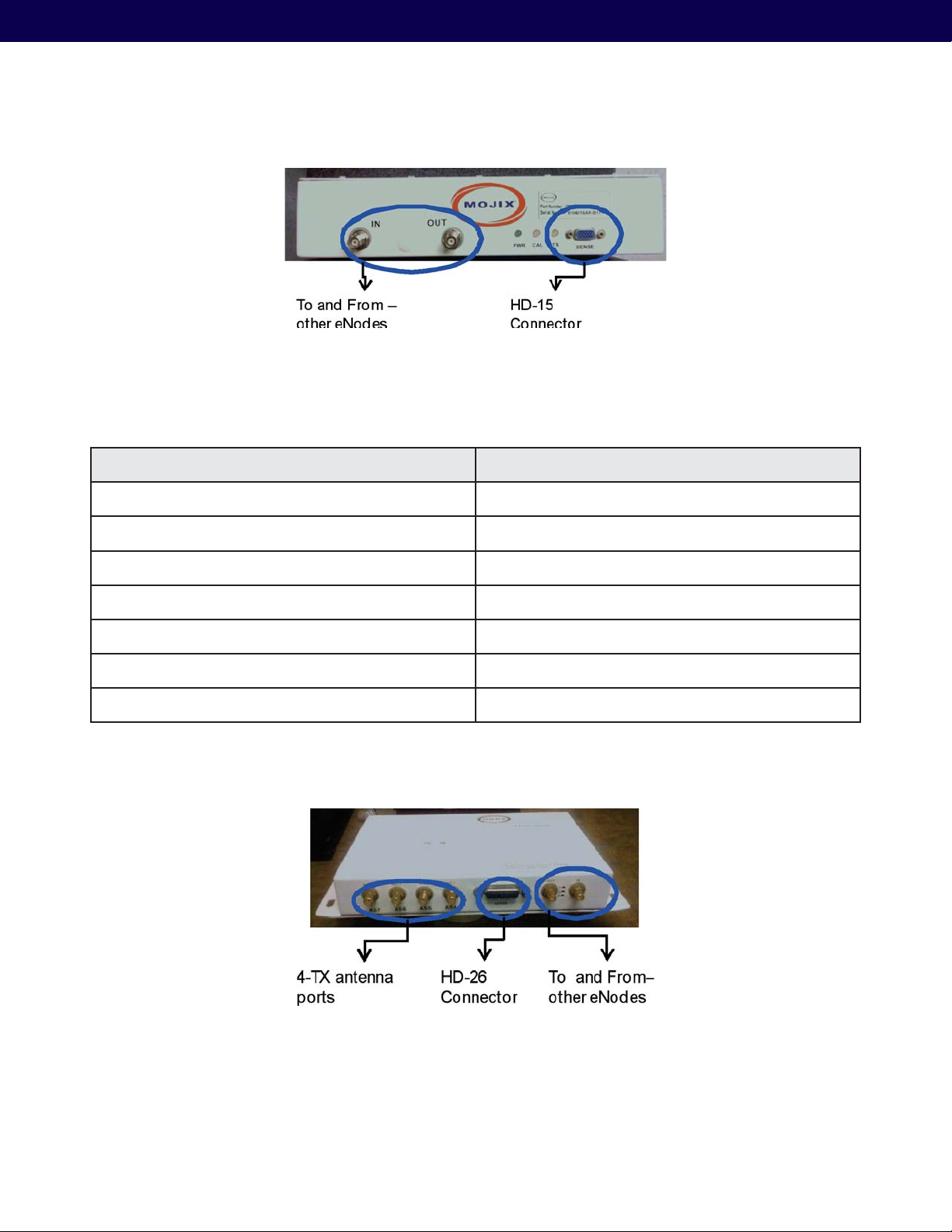
Figure 15: Single-Port eNode
3.3. 4-port eNode cabling
Figure 16 depicts the 4-port eNode and its connectors, which are specified in the following table.
4-port eNode Specification Comment
RF input connector SMA connector
RF output connector SMA connector
Antenna – 1 output connector R-SMA connector
Antenna – 2 output connector R-SMA connector
Antenna – 3 output connector R-SMA connector
Antenna – 4 output connector R-SMA connector
External I/O connector HD-26
Table 6: 4-Port eNode cabling requirements
18
Figure 16: 4-port eNode, showing the cabling requirements
Page 19
Mojix® STAR 1000 System User Manual
4. eMux Installation
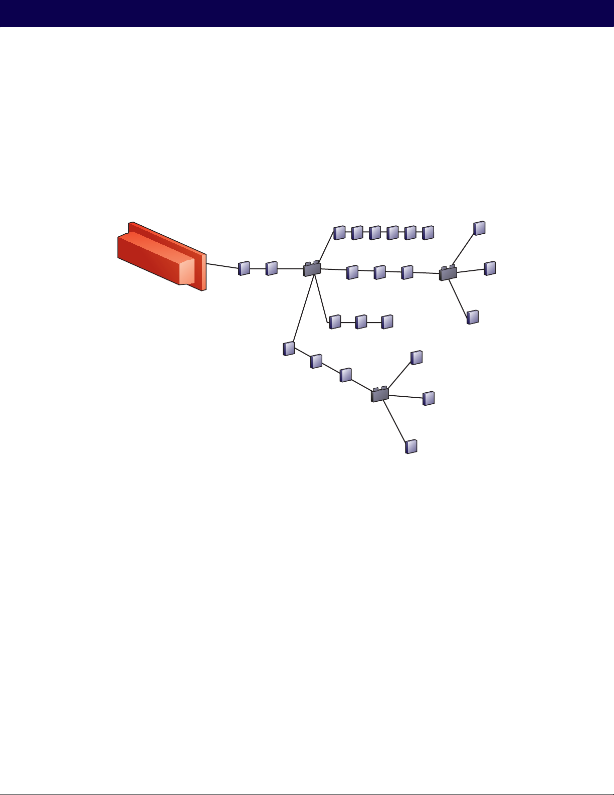
eNodes frequently are deployed with multiplexers (eMux’s) that can connect multiple eNodes to a STAR or to another
(upstream) eMux. The eMux amplifies and conditions RF signals from the STAR and provides DC power to eNodes.
This section describes the steps to installing an eMux. eMux’s should be used either when:
(1) The insertion loss from coaxial cables and eNodes is too great
(2) The wired eNode system layout requires splitting the wiring to multiple wiring branches.
Star Receiver
STAR
eMux
eNode
Figure 17: Example wiring diagram for eNodes and eMux’s
4.1. About Insertion Loss
The STAR puts out a signal of +22 dBm. Approximate insertion loss of terminated LMR240 coaxial cable at 915 MHz is
~7.5 dBm per 100 ft. Approximate insertion loss of wired eNodes is 0.5 dBm. If the input power level on coaxial cable
as an input to either an eMux or an eNode must be greater than or equal to -10 dBm. If the power level falls below this
level, eNodes may miscalibrate causing the middle yellow LED to blink, or even go dark. In order to increase the signal
strength for longer cable runs or many eNodes strung together, an eMux can be used to amplify the signal.
4.2. eMux Specifications
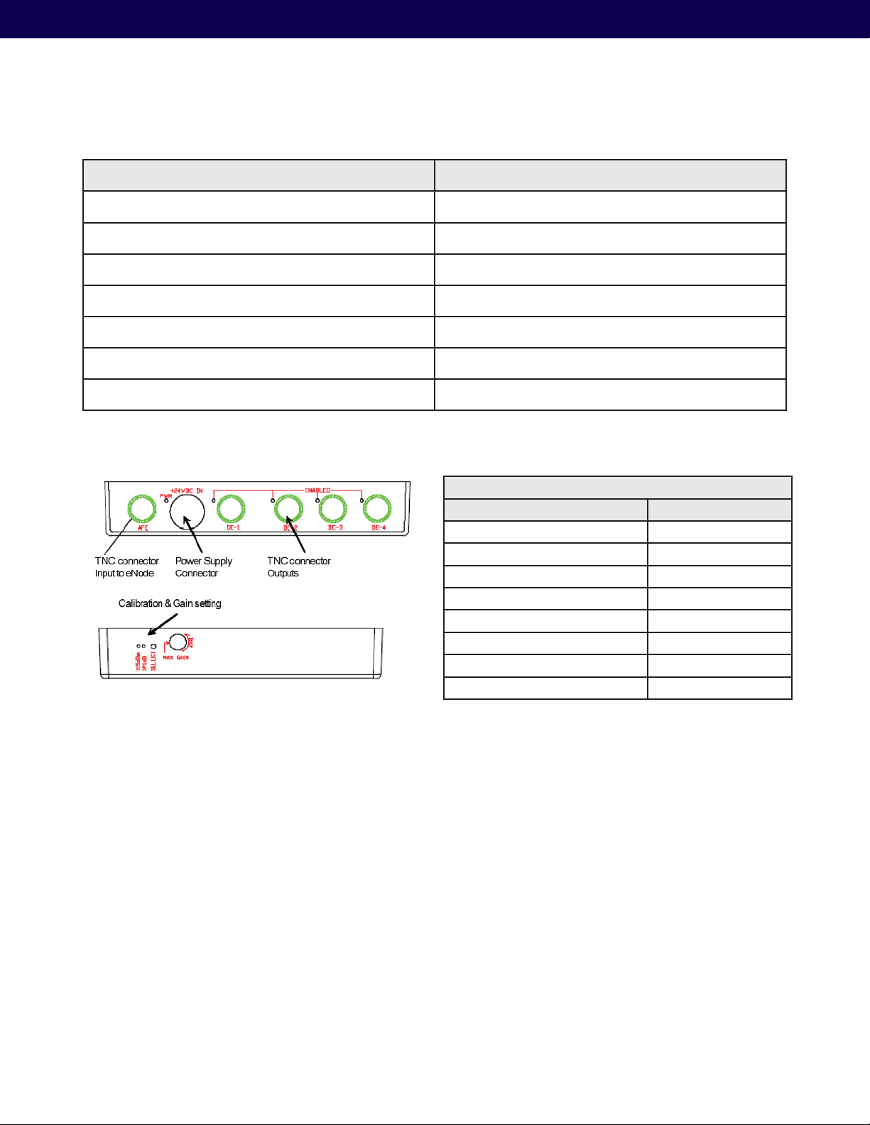
Figure 18 depicts the eMux and its interfaces, showing the RF connections as well as the power supply and calibration
dial. The connector specification is summarized in Table 8.
19
Page 20
eMux Specification Comment
RF input connector TNC connector
RF output connector – 1 TNC connector
RF output connector – 2 TNC connector
RF output connector – 3 TNC connector
RF output connector – 4 TNC connector
Calibration Pin See eMux Calibration (Section 7)
Power supply connector External power supply
Table 7: eMux Cabling Specification
Mojix eNode Multiplexer Specifications
Parameter Specification
Signals Present at Input/Output DC, RF and Control
RF Frequency Range 902-928 MHz
RF Signal Level (Max.) +20 dBm (output)
Input Connector TNC
Output Connector 4 TNC’s
Input Impedance 50 Ohm
DC Input 24 V
DC Input Connector Male Power Jack
Figure 18: eMux Physical Diagram
Table 8: eMux Operating Specification
Additional information about eMux calibration can be found in Section 6.3: eMux Calibration. However this step should
be done after initially setting up all system components.
20
Page 21
Mojix® STAR 1000 System User Manual
5. Master Controller Installation
5.1. Master Controller (MCON) Hardware requirements
MCON requirements (supplied by Mojix) are:
Linux Operating System †
Memory : 4 Gigabytes †
Hard disk : 150 Gigabytes †
Processor: 3.0 GHz Intel Xeon Dual-Core †
Please note that this hardware is currently only available through Mojix as a turnkey appliance.
5.2. MCON Deployment overview
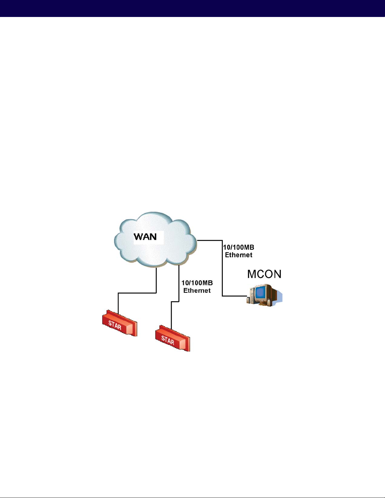
The MCON is connected to the STAR via its Ethernet interface.Figure18 illustrates a typical deployment scenario. The
figure illustrates that a single MCON can interface with and manages one or more STAR Receivers.
Figure 19: STAR System Network Configuration
21
Page 22

6. System Configuration
The MCON has the flexibility to configure and manage the STAR unit through 2 very specific interfaces. The utilities
for these interfaces are primarily the Web Graphical User Interface and secondly an engineering Client called Mojo.
Additionally, the MCON publishes tag data out through a variety of standardized interfaces for 3rd party integration. These
interfaces include Microsoft Biztalk Provider, Web Service Definition Language (WSDL), IBM Websphere, and ALE.
6.1. Network Setup
6.1.1. Connecting to the MCON
The MCON by default uses DHCP for IP assignment. If a DHCP server is not found within 5 minutes of the power up,
the MCON uses the following default IP address.
Default Static IP: 169.254.1.1 †
Default Netmask: 255.255.0.0 †
Default Gateway: 169.254.1.1 †
Recommended to connect MCON using loopback/crossover cable directly to a windows PC – for first time setup. †
This will ensure that MCON defaults to the IP address above after 5 minutes. If the MCON is instead connected to
a LAN with DHCP server, it may acquire a different IP address, making it difficult to locate on the network for first
time setup.
The STAR Receiver strictly uses a static IP address with the following default settings.
Default Static IP: 169.254.1.2 †
Default Netmask: 255.255.0.0 †
Default Gateway: 169.254.1.1 †
6.1.2. Changing Network Settings
Changing the IP of the MCON: The simplest way to change network settings on the of the MCON is to simply
navigate a web client to
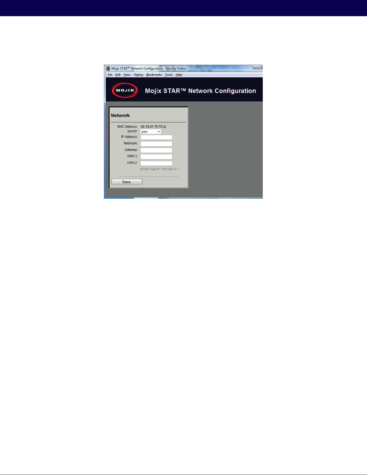
interface is the preferred way to configure network and operational system parameters. The following figure shows the
network configuration screen:
http://<IP-address-of-mcon>/network and changing settings from this screen. This web
22
Page 23
Mojix® STAR 1000 System User Manual
Figure 20: Network Configuration
Changing the IP of the STAR: To change the STAR IP requires a telnet session. The following examples assume the
availability of a telnet Client, such as PuTTY (
http://www.chiark.greenend.org.uk/~sgtatham/putty/download.html
).
The same PuTTY Client can be used to establish a Telnet connection. Likewise, a telnet session from the MCON
command prompt or a Windows XP command prompt may be used as well.
First establish a Telnet session with the STAR as follows.
$ telnet 169.254.1.2
Once connected, there will be no prompt presented and the characters will not be echoed either. To change the
network settings the user must be connected to the STAR from the same LAN segment and not over a WAN
connection. Enter the following commands in this order.
1. gateway <Gateway ip address (Ex. 192.168.1.1)>
2. netmask <Netmask (Ex. 255.255.255.0)>
3. ip <ip address (Ex. 192.168.1.2)>
All setting changes are immediate. Once the IP is changed, the user must re-establish a telnet session to the new
address. The last step in this process is to save the settings in flash memory. To do this, establish a new telnet session
with the STAR at its new address. Using the example IP from above of 192.168.1.2, enter the following commands.
$ telnet 192.168.1.2
sys commit
This will commit the new settings to flash memory, making the new network settings permanent. The system will
return a message indicating that the Kernel commit to flash has been verified, as indicated in the Figure that follows.
23
Page 24
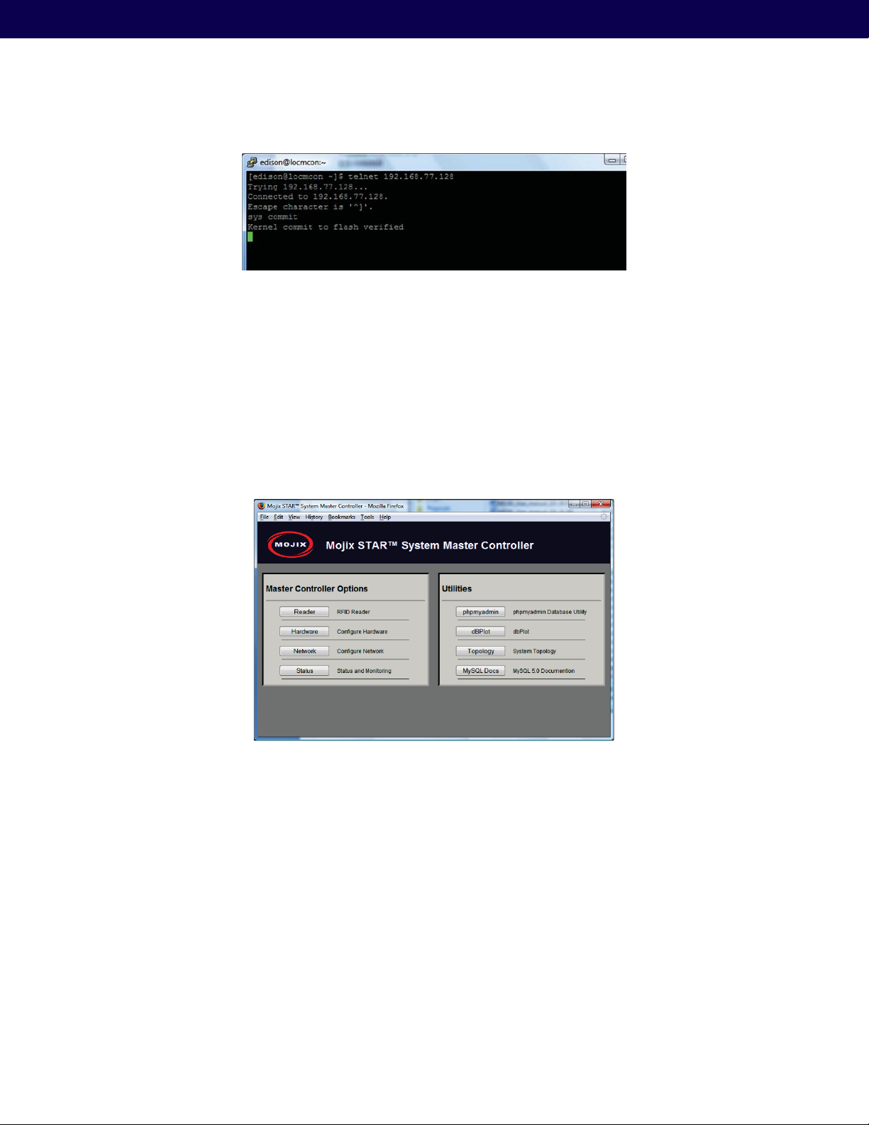
Figure 21: Committing Network Settings
To exit from a telnet session, the user must enter ‘ctrl-]’ and then type “quit” (ctrl = control key).
6.2. Graphical User Interface
The Web Graphical User Interface (Web GUI) provides the user a simplified HTTP based interface to configure and run
the system. Currently, the only supported browsers are Mozilla Firefox and Microsoft Internet Explorer. To launch the
Web GUI, enter the MCON IP address in the URL field of the browser. Not all screens are described in this version of
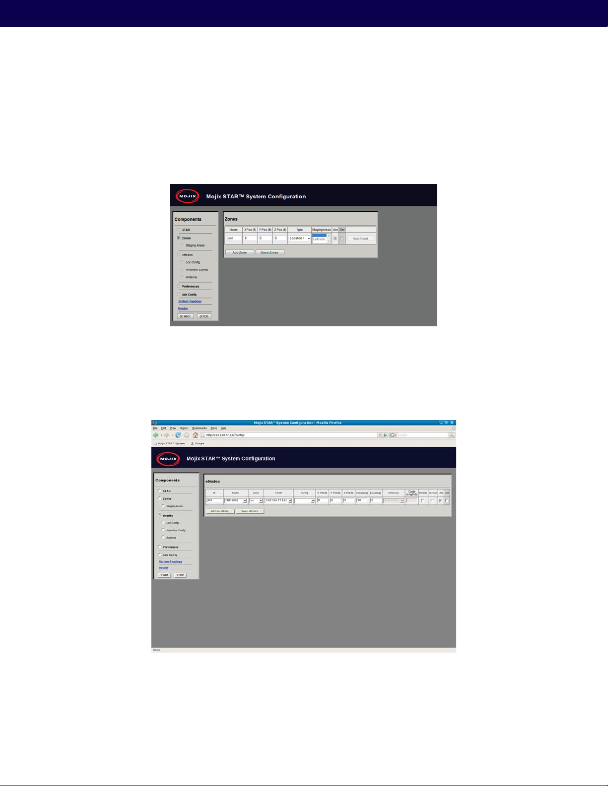
documentation. The following screen is the landing page for the system.
Figure 22: Main Web Control Landing Page
From this interface, the user has access to various utilities for configuration and execution of the system. When
presented with a Username and password, enter the default credentials as follows:
Username: edison
Password: m0j1xInc
24
Page 25
Mojix® STAR 1000 System User Manual
This interface is divided into 2 sections: Master Controller Options and Utilities. The Master Controller Options area
allows the user to configure and run the system. The Utilities area allows the user to run diagnostic utilities.
6.2.1. Hardware Button
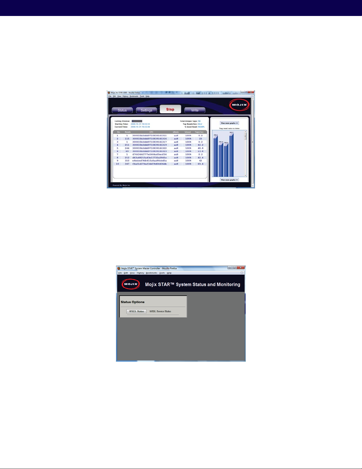
The Hardware Button launches the configuration interface for the STAR.
Figure 23: STAR Receiver Setup and Configuration
This interface shows a configuration menu frame on the left and configuration input fields on the right. Beginning with
the STAR configuration, the user must first enter the IP address of the STAR under the “Name” input field.
Figure 24: eNode Setup and Configuration
For information about setting up zones and location information, see Appendix A.
25
Page 26
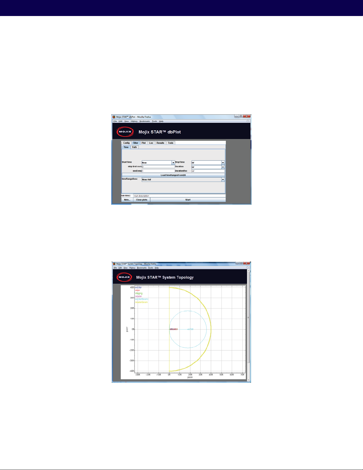
6.2.2. Reader Button
The Reader Button launches an interface that gives the user controls to run the system.
Figure 25: Reader Interface – showing tag reads
6.2.3. Network Button
The Network Button launches an interface to configure network settings for the STAR and MCON, and was discussed
early in Section 6.1.2 and shown in Figure 19.
6.2.4. Status Button
The Status Button launches an interface used to view diagnostic messages.
Figure 26: System Status, and Diagnostics
26
Page 27
Mojix® STAR 1000 System User Manual
6.2.5. Phpmyadmin Button
This Button launches password protected MySQL browser utility and should only be used by advanced users.
6.2.6. dbPlot Button
The dbPlot Button launches a Java application that provides various graphical diagnostic functions.
Figure 27: dbPlot, graphical diagnostics
6.2.7. Topology Button
The Topology Button launches a diagram of the system topology as configured by the user.
Figure 28: System Topology graphical display
27
Page 28
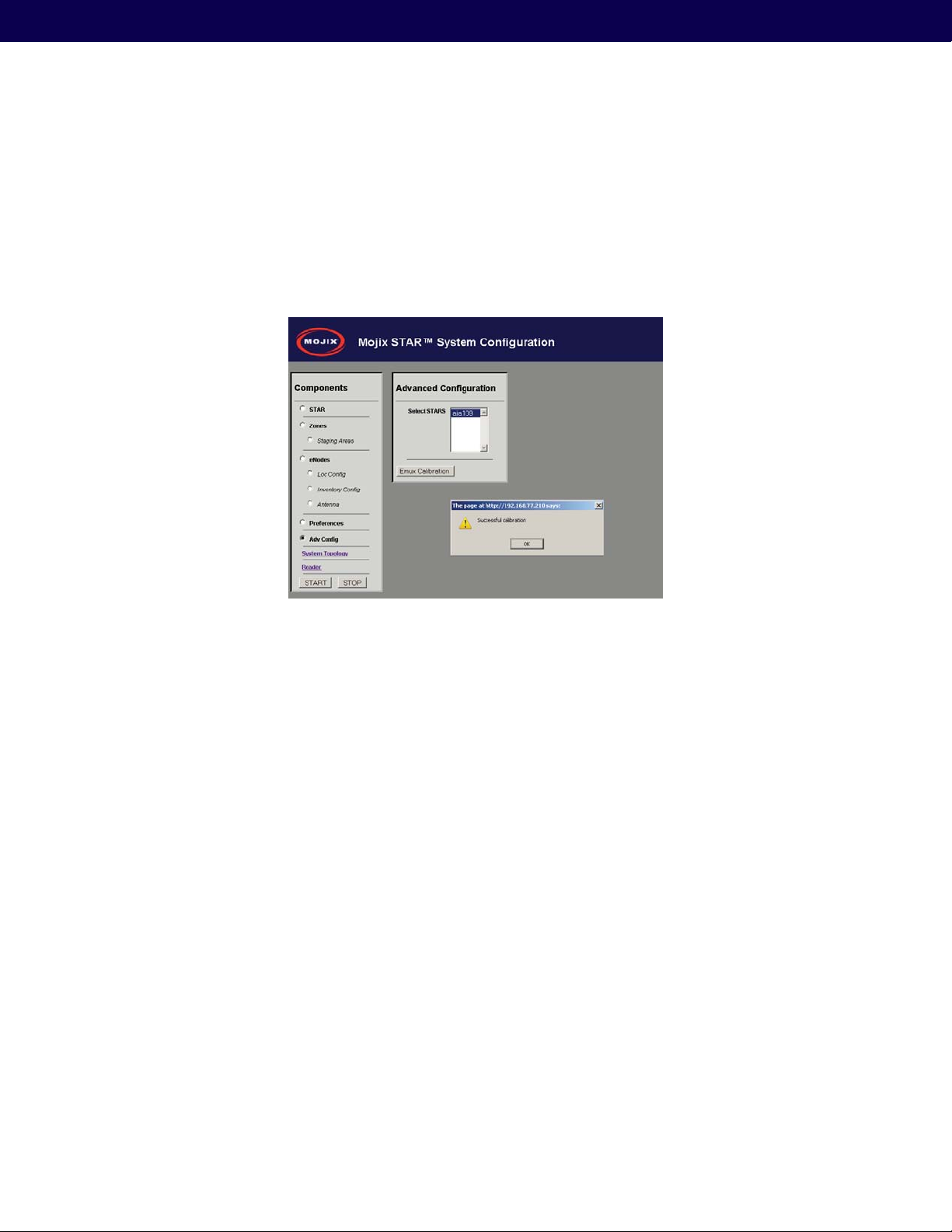
6.3. eMux Calibration
eMux’s must be calibrated to ensure that they amplify the STAR’s signal correctly. Improperly calibrated systems will
either exhibit mis-calibrating eNodes which can be seen from the eNode calibration (middle) LED blinking slowly or not
illuminating at all when directed to excite tags. In newer systems, an eMux Button on the Web GUI allows for remote
calibration by simply pressing the Calibration Button once all hardware has been connected and powered on. This
process should be done after changing any cable lengths or eNodes prior to collecting data.
Figure 29: eMux Calibration
Step 1: Click the Adv Config Button
Step 2: Select the STAR Receiver whose emuxes you are calibrating
Step 3: Click the “Emux Calibration” Button
Step 4: Receive Confirmation and Click OK
28
Page 29
Mojix® STAR 1000 System User Manual
Appendix A: Location Configuration Guidelines
This section describes the setup and installation notes to estimate location. For most algorithm variations, the location
and orientation of the receiver and eNodes is essential for determining tag location. What follows is the description of
the coordinate system and the system components in it as well as how to enter this information so that it is accessible
by the software applications.
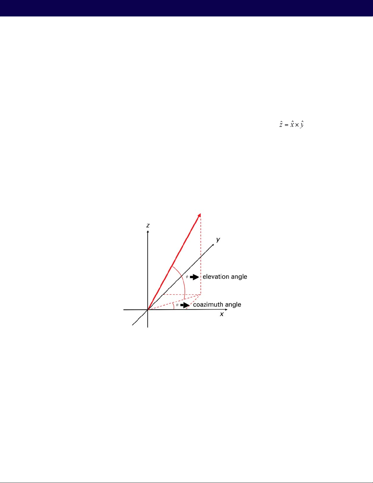
The location and orientation of both reader and eNodes will be made with respect to a coordinate system that must
be defined. The relationship between vectors x, y and z must follow the right hand rule, that is :
denotes the vector product. The figure below shows an example of the relation between x, y and z.
The two angles that describe the beam boresight of both reader and eNodes must also be entered. These angles can
be seen in Fig. 1 and are defined as follows:
coazDeg: coazimuth angle, in degrees. It is an angle that starts at zero in the +x-direction, and increases moving toward
+y-direction.
where x
elevDev: elevation angle, in degrees. Zero at the horizon, increases to +90 when pointing up.
Figure 30: Coordinate system
The last entry that must be configured is the reader roll angle. It indicates the rotation of the reader on its own axis (the
axis that corresponds to the beam boresight). The rotation values are as follows:
with power cord down, boresightRollDeg = 180
with power cord up, boresightRollDeg = 0
As a check on reader orientation, the 3rd element is at the end with the Ethernet connection. Look at dbPlot location
plot for the 4 antenna elements to make sure the boresightRollDeg field was entered correctly. The following table
illustrates a partial description of the fields.
29
Page 30

Property Comment Example
aiaDottedIP, aiaName Network address and reader name 192.168.77.100, ‘aia109’
posXFt The X position (ft) of the STAR reader 0.0
posYFt The Y position (ft) of STAR reader 0.0
posZFt The Z position (ft) of STAR reader. The ground is usually
chosen to have a z coordinate of 0, so this represents the
height of the reader.
boresightCoazDeg Coazimuth, in degrees, of the direction the reader is pointing.
0 (reader pointed along
This is the usual math convention on angle, where +x is 0deg,
+y is 90deg, -x is 180deg, -y is 270deg
boresightElevDeg Elevation, in degrees, of the direction the reader is pointing. If
0 (horizontally pointed
eNode points horizontally, will be zero
boresightRollDeg Roll angle, in degrees, of the reader. If the power cord is
down, the roll is 180deg. If up, 0 deg
Table 10: STAR Receiver Location Configuration Parameters
Property Comment Example
txID ENode ID in hex 0xa01
posXFt The X position (ft) of the eNode 0.0
posYFt The Y position (ft) of STAR reader 0.0
5.0
x-axis)
star)
180.0
posZFt The Z position (ft) of eNode. The ground is usually chosen to
have a z coordinate of 0, so this represents the height of the
reader.
boresightCoazDeg Coazimuth, in degrees, of the direction the eNode is pointing.
This is the usual math convention on angle, where +x is 0deg,
+y is 90deg, -x is 180deg, -y is 270deg
boresightElevDeg Elevation, in degrees, of the direction the eNode is pointing. If
eNode points horizontally, will be zero
Table 11: eNode Location Configuration Parameters
30
5.0
0 (eNode pointed along
x-axis)
0 (horizontally pointed
eNode)
Page 31

Mojix® STAR 1000 System User Manual
Here are some examples of the coordinate systems that can be chosen (Always use x and y as the horizontal
coordinates.)
1) Pick reader as origin, the direction it points as the x-axis
STAR Receiver parameters (posXFt, posYFt, posZFt, boresightCoazDeg, boresightElevDeg) are all zero.
2) Use walls as axes
– best for using laser rangefinder
– only valid if there are two walls at right angles and nice and flat
3) Choose a corner eNode as the origin
– good if eNodes are in a grid
– reader is then offset from corner/reference eNode
31
Page 32
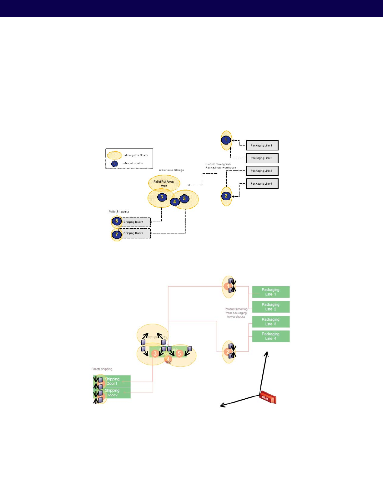
Appendix B: Deployment Example
B.1 STAR Topology Examples & Deployment
This appendix illustrates an example topology and deployment following figure illustrates interrogation spaces and
targeted locations for installing eNodes (i.e. labeled one through seven). The figure below shows the eNodes and their
associated pointing angles, as well as the position and pointing of the STAR receiver.
Figure 31: eNode Zones Example
32
Figure 31: Deployment Example Showing eNode Zones
Page 33
Mojix® STAR 1000 System User Manual
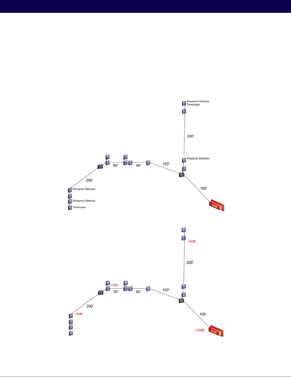
B.2 STAR System Cabling Example
The following figure illustrates an example, showing the cable lengths between each segment of an example
deployment. From the drawing, a measurement the insertion loss of each segment is computed, as shown in the
figure below. This information is used for placing the eMuxes, to maximize power distribution across all eNodes. Keep
in mind that cable runs need to run from eNode to eNode, but may also have to run up and down from the ceiling to
the eNode itself. In many cases, cabling may not run in a straight diagonal line as shown, but instead may need to run
along beams vertical or horizontal.
Figure 33: Example – Showing eNode, eMux and STAR cabling
Figure 34: Example Showing Cable Losses
33
Page 34
Appendix C: Advanced Troubleshooting
C.1 Accessing the Command Line
For advanced configuration working beyond the web interface of the MCON, users will need an SSH Client, a VNC
Client and an FTP Client capable of using the SFTP protocol. The following list provides 3 suggested utilities and
corresponding links.
1. SSH Client – PuTTY:
2. VNC Client – RealVNC: http://www.realvnc.com/
3. FTP Client – Filezilla: http://filezilla-project.org/
C.2 Additional Ways to Change MCON Network Settings
To change the IP of the MCON, the user will need to establish an SSH connection (TCP port 22) with the MCON. The
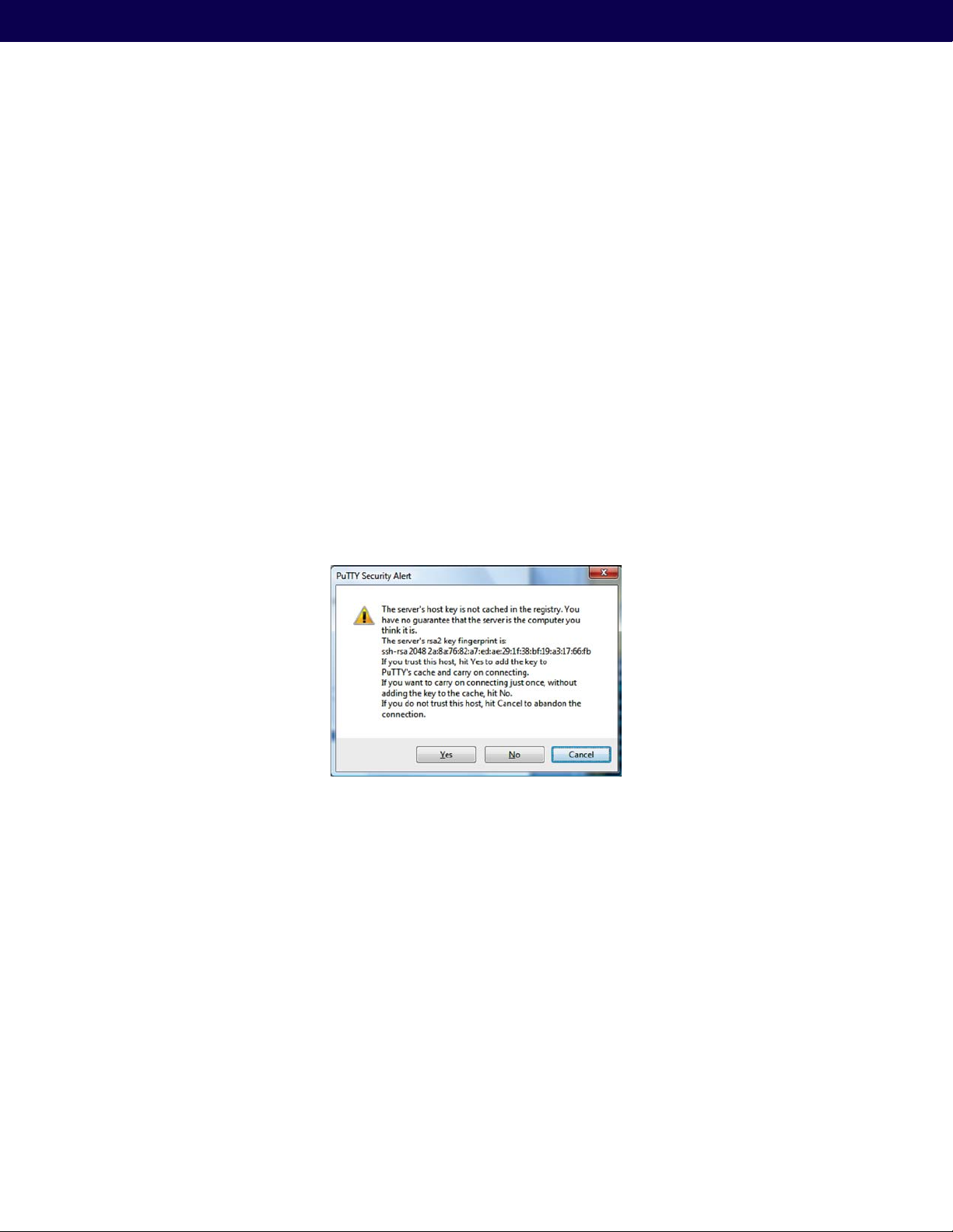
first time a user connects with the MCON, the user will be asked to agree to accept a host key for the connection that
will be cached in the registry from that point further. When asked, click on “Yes” or simply agree, depending on which
type or Client is being used. The figure below shows an example of this confirmation dialog window.
http://www.chiark.greenend.org.uk/~sgtatham/putty/download.html
Figure 35: SSH Host Key Confirmation
To connect to the MCON, use the following credentials.
Username: edison
Password: m0j1xInc
Once connected, the user is presented with a command prompt. At the prompt, enter the following command:
$ sudo setup
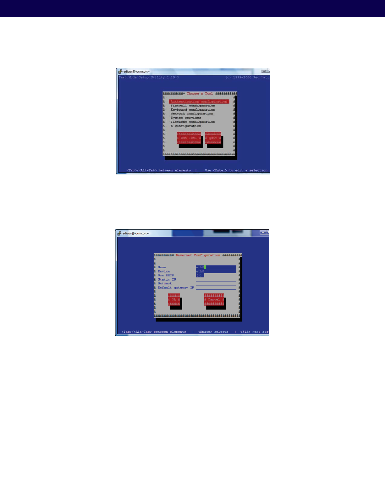
The user will be presented with an interface that allows for the configuration of several parameters as shown in the
following figures.
34
Page 35
Mojix® STAR 1000 System User Manual
Figure 36: Setup Screen
Scroll down to the Network configuration and hit “enter”. From here, select the eth0 interface, which will present the
following screen.
Figure 37: Eth0 Configuration
From here the user can enter any fixed IP address or select DHCP. Once the changes are made, select “Ok” and
Quit out of the setup utility. The user will once again be presented with a command prompt ($ ). For the new network
changes to take place the user must enter the following command.
$ sudo service network restart
The user should note that once this command is issued the new network settings will take place immediately, requiring
the user to re-establish the SSH connection using the new IP address.
35
Page 36
C.3 Connecting to the MCON
A VNC Client is used to establish a remote desktop connection with the MCON and is required to run a Mojix
configuration and diagnostic utility called Mojo. To establish a VNC connection, enter the following command at the
command prompt.
$ sudo service vncserver start
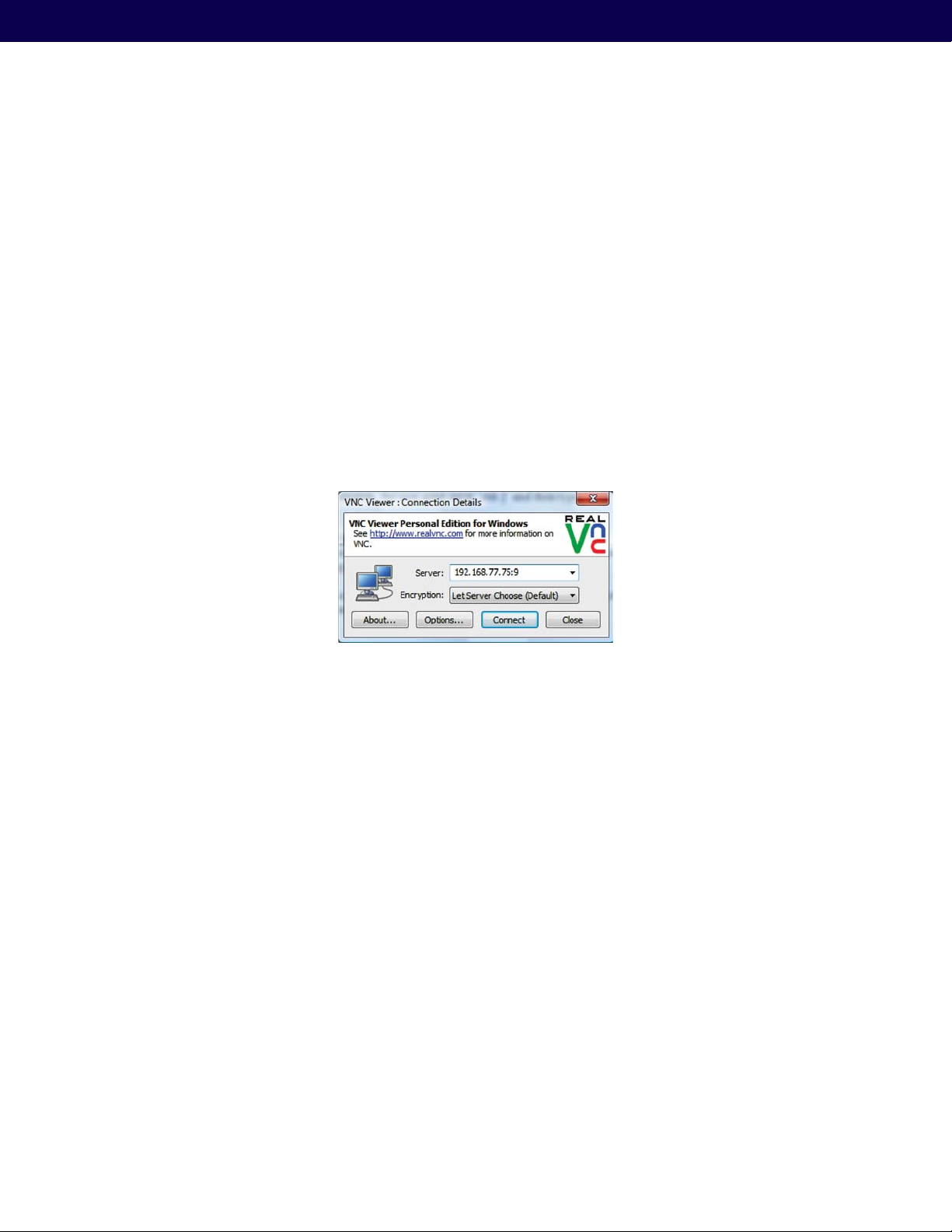
Now the user can run a VNC Client and connect to the MCON using the following connection address and session
number format.
<ip of MCON>:9
This indicates that session 9 is used to establish the VNC session with the MCON. The following illustrates an example
connection through the RealVNC Client interface.
Figure 38: VNC Client Connection Window
The password to establish the VNC connection is: m0j1xInc
36
Page 37
Mojix® STAR 1000 System User Manual
Appendix D: Engineering Interface — Mojo
Mojo provides users with an integrated interface for both configuration and execution of the system. The functions of
this interface are summarized as follows:
STAR Parameter Configuration †
eNode Configuration †
Inventory Program Generation †
System Operation †
To run Mojo, the user must connect to the MCON using VNC and bring up a terminal window by clicking on the
Terminal icon on the desktop. With the terminal window open, enter the following command to launch Mojo:
$ Mojo <STAR ip>
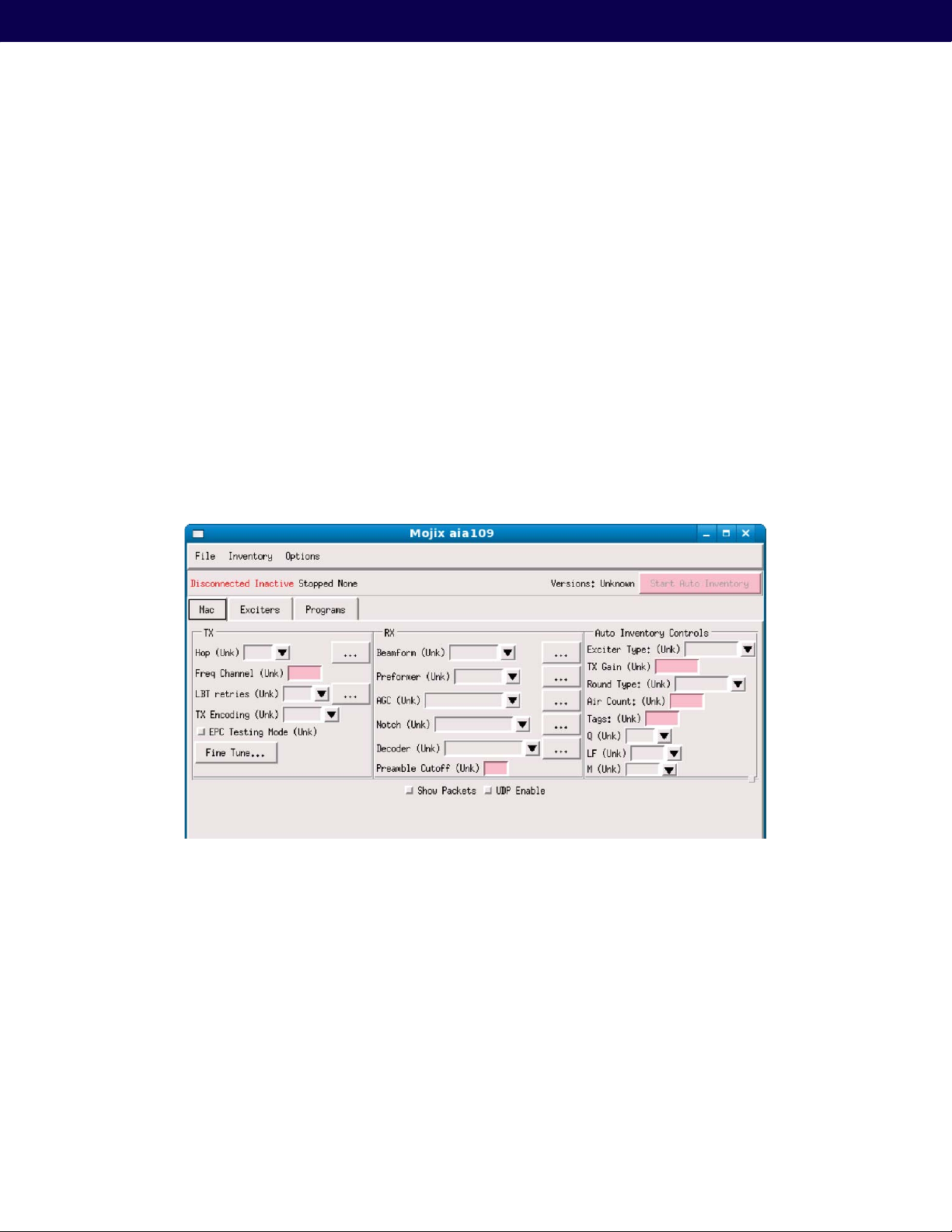
This will launch the Mojo application and the user will be presented with the following screen.
Figure 39: Mojo Main Screen
From here the user must click on the “File” menu and select “Connect”. This will establish a connection between the
Mojo Client application and the STAR. At this point, the user can make real-time configuration changes. The most basic
configuration to begin reading tags would be to enter one or more eNode addresses in the “Exciters” tab as shown in
the following figure.
37
Page 38
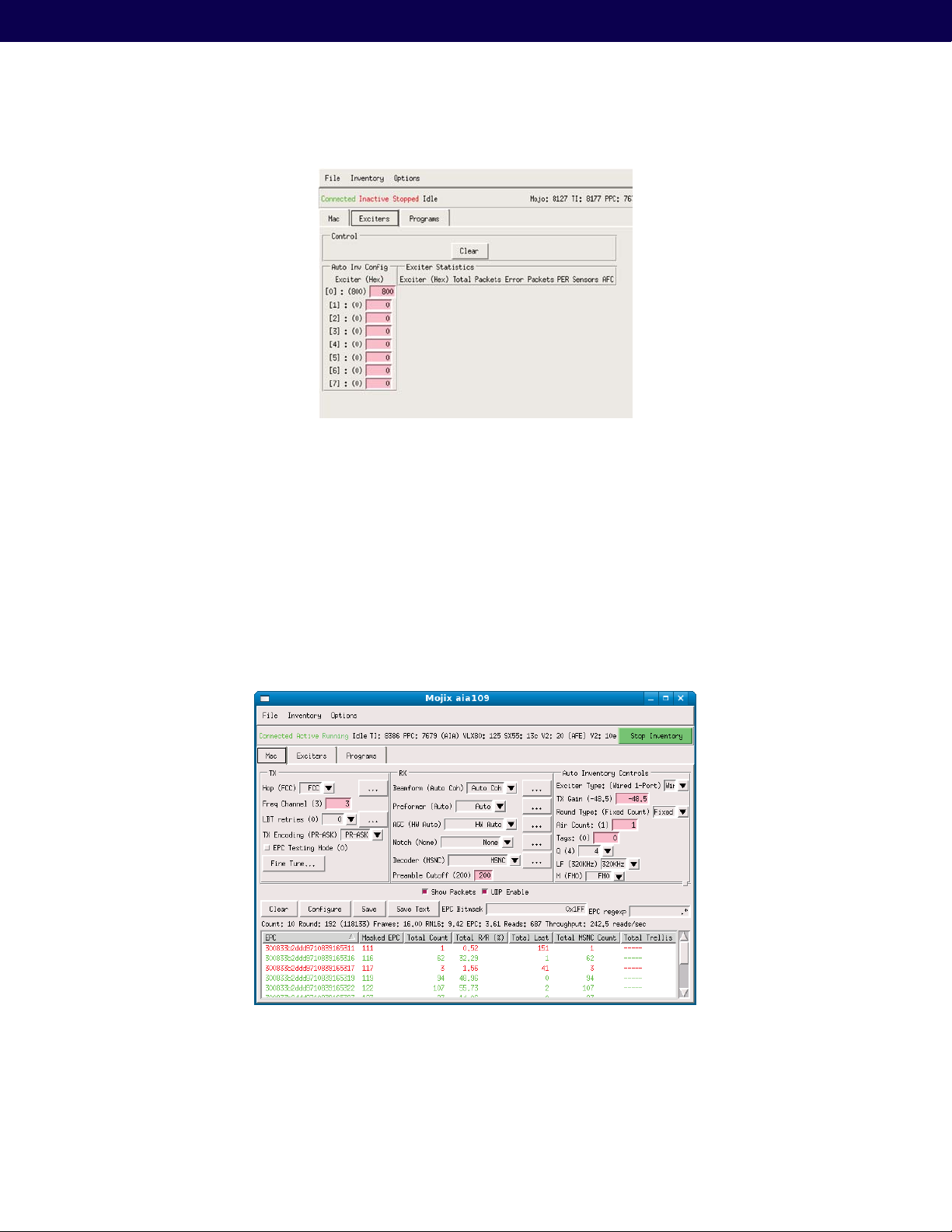
Figure 40: eNode Configuration (eNode Tab)
The address of an eNode is written on the eNode itself as the last three digits of the serial number. The number is
presented as three hexadecimal digits, for example, B89. The user must use the Enter key when entering the eNode
addresses in this window for the values to be accepted. Note, when the value is accepted it will appear in parenthesis
to the left of the text entry box.
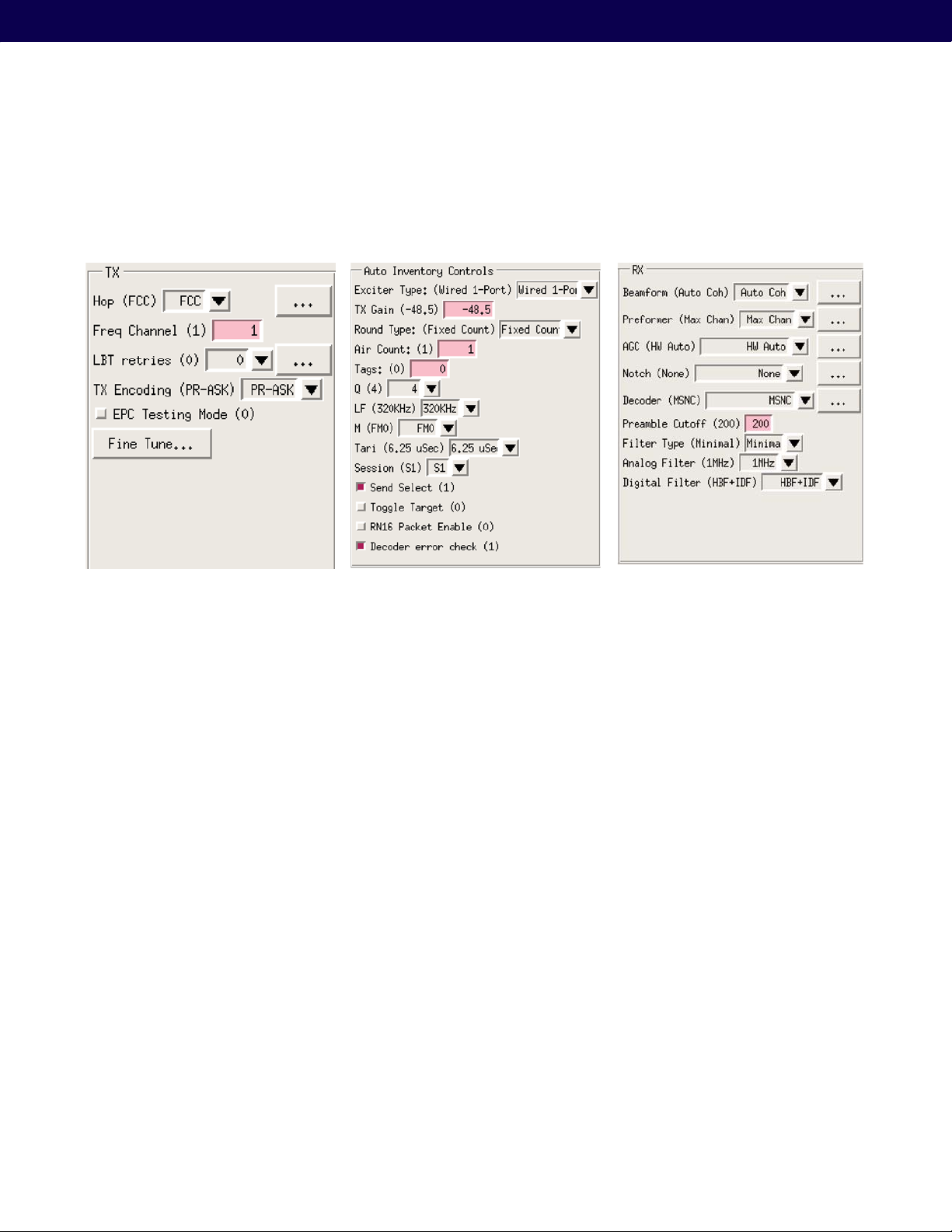
Once the eNodes are entered, the user can return to the “Mac” tab and click on the “Start Auto Inventory” Button in
the top right corner. The Button will turn green when the system is running and the Button text will change to “Stop
Inventory”. This is how to start and stop tag reads. To view tag reads, the user must select the “Show Packets” check
box as shown in the following figure.
38
Figure 41: Tag Reads
Page 39
Mojix® STAR 1000 System User Manual
Note that selecting the “Show Packets” box will redirect tag reads away from the MySQL database and to the Mojo
interface for display. Unselecting the box will return tag reads to the database. The EPC display area at the bottom of
the Mojo screen shows active tag reads.
Figure 42: Transmit Parameters Figure 43: Auto Inventory Controls
Figure 44: Receive Parameters
39
Page 40
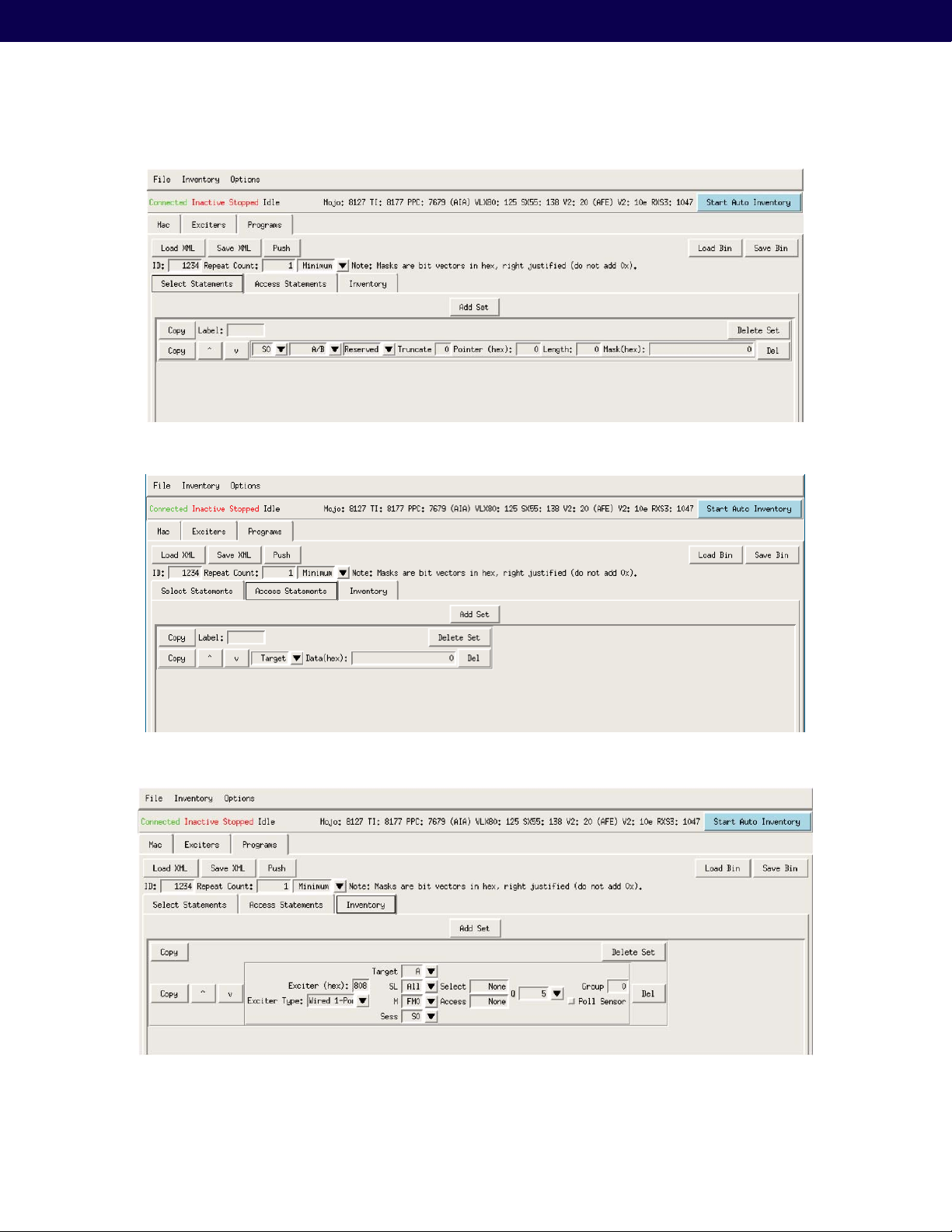
Figure 45: Select Statements
Figure 46: Access Statements
40
Figure 47: Inventory Programs
Page 41

Mojix® STAR 1000 System User Manual
Appendix E: Manual eMux Calibration
eMux’s are generally manually calibrated as they are being installed as they may be in hard to reach areas. To manually
calibrate an older revision eMux, you will need:
(1) A connected system with all devices prior to the needed eMux including:
a. A networked STAR receiver
b. A networked master controller
c. All planned eNodes between eMux and STAR connected
(2) A spectrum analyzer (with DC Block and TNC male connection)
(3) A small flat head screw driver with at least a 2” neck
(4) A power source where the eMux is to be implemented
(5) An eMux with power brick
(6) A terminated LMR240 cable with known loss (recommend 1 dB.)
Step 1: Set the STAR to Transmit a single channel tone
1. From Mojo application, select single channel by turning frequency hopping off.
2. On diagnostics tab, type startcwtx
Step 2: Plug the power cable into the eMux and connect the coax cable planned as the input to the eMux to a
spectrum analyzer
1. Be sure to connect the spectrum analyzer through a DC Block.
significantly damage the spectrum analyzer.
2. You may need an adapter to connect your spectrum analyzer to the DC Block, or to the coaxial cable. LMR240
coaxial cable is straight TNC for Mojix systems.
Step 3: Measure the power level of the signal from the coaxial cable (planned to go into the input port on the
eMux) and record this level. This level must be above -10 dBm.
1. If the signal planned to come into the input port is below -10 dBm, you must put the eMux into the system
earlier in the chain where there is less insertion loss.
2. After measuring the power level, connect the coaxial cable directly into the input of the eMux.
3. Record the serial number of the eMux.
Warning: failure to use a DC Block could
Step 4: Determine which output port will have the most gain.
1. With the input connected on the eMux, connect a cable to the first output port of the eMux (the output port
closest to the power supply connection.)
2. Attach the other end of the cable to an available eNode.
41
Page 42

Step 5: Set the gain to the maximum output level.
1. Using a small slotted edge screwdriver, adjust the gain control by turning in a clockwise direction until the
green light turns on, but the red light is off.
2. Continue turning the adjustment clockwise until the red light turns on.
3. Once the red light is on, turn the adjustment counter-clockwise by a single click.
Step 6: Connect all needed coaxial cables planned to branch from the eMux.
1. Connect coaxial cables intended as outputs to the eMux output ports. The most challenging branch from
an insertion loss perspective should be attached to the port with the most gain. The difference in gain from
the first port and the 4th port is 2 dB. The maximum output setting based on this calibration method will be
+23 dBm
2. Label the output cables and record to which port each coaxial cable is connected
Step 7: Restore STAR to normal operation
1. On diagnostics tab, type stoptx
2. From Mojo application, turn frequency hopping back to the appropriate setting for your geography.
42
Page 43

Appendix F: Glossary
Mojix® STAR 1000 System User Manual
AIDC: Automatic identification and data collection.
Active Tag: RFID tags with their own internal power
source, which is used to power the integrated circuits and
to broadcast the response signal to the reader. Active tags
typically beacon their identifier at fixed intervals and can
feature sensor information and extended memory. (See
also “passive tag” and “semi-passive tag.”)
Air Interface: The means used to wirelessly enable tagreader communications.
Antenna Polarization: The orientation of the antenna’s
electromagnetic (EM) field. Polarization often implies a
preferred tag-antenna orientation which optimizes the
antenna’s ability to acquire tag signal and data. Technically,
polarization relates to the orientation of EM fields at
specific antenna components. In user-level discussions,
however, polarization is typically referenced to the ground
and assumes the antenna is in its normal mounting
position. If, for example, a horizontally polarized (parallel
to the ground) antenna that is normally mounted upright
on a beam or wall were mounted on its side instead, it
would then be thought of as being vertically polarized
(perpendicular to the ground) from the user’s perspective,
though the antenna’s inherent polarization never changes.
Anti-collision: The ability of a reader to read multiple tags
in the field (read window) virtually simultaneously. (See
“discrimination.”)
Beamforming: A signal processing technique used
in sensor arrays for directional signal transmission
or reception. This spatial selectivity is achieved by
using adaptive or fixed receive/transmit beampattern.
Beamforming takes advantage of interference to change
the directionality of the array. When receiving, information
from different sensors is combined in such a way that the
expected pattern of radiation is preferentially observed.
Beam steering: Changing the direction of the main lobe
of a radiation pattern. In radio systems, beam steering
may be accomplished by switching antenna elements or
by changing the relative phases of the rf signals driving
the elements.
Chip: (See “integrated circuit.”)
Coax: Coaxial Cable.
DepCon: (See “Master Controller.”)
Deployment Controller: (“See Master Controller.”)
Discrimination: The ability of a reader to read individual
tags in a field containing multiple tags, or the ability
of the system to determine efficiently what to report.
Discrimination with regards to tags uses anti-collision
algorithms (See “anti-collision.”) Discrimination with
respect to interrogation zones uses information to
determine how best to report in which interrogation zone
a tag is located (See “interrogation zone.”)
Attenuate: To decrease the broadcasting range of an
antenna’s signal.
Backscatter (backscatter modulation): A method
of tag-reader communication that uses radio frequency
(RF) energy broadcast from a reader/antenna to
essentially bounce the RF signal off the tag and back
to the reader. The tag encodes its own identification
data on the original signal and reflects (backscatters) the
modified (modulated) signal back to the reader’s receiver.
The alternative to backscatter technology is transmitter
technology (see “active tag 1”). Backscatter tags may
be powered solely by the reader’s signal or may include
a battery for increased read range or to power an
onboard processor.
Beam-Powered Tag: A tag whose internal circuitry is
energized by converting a portion of the reader’s RF signal
(“beam”) to power that enables it to modulate and reflect
(backscatter) that signal to the reader. (See “passive tag 2.”)
Electronic Product Code (EPC): An ultra-low-cost RFID
tag containing a 64-bit or 96-bit unique ID codes—the
equivalent of the bar-coded UPC (Universal Product Code)
plus additional data not accommodated by UPCs. The EPC
tag falls under AIDC Class 1.
™
eGroup
: Electronic manifest of a targeted population
of tags that enable true electronic proof of delivery and
heightened levels of anti-counterfeiting, security and
authentication.
EM: Electromagnetic.
eMux: eNodes frequently are deployed with multiplexers
(eMux’s) that can connect up to ten eNodes to a STAR
or to another (upstream) eMux. The eMux amplifies and
conditions RF signals from the STAR and provides DC
power to eNodes.
43
Page 44

eNode: Each Mojix eNode excites all passive RFID tags
within its designated interrogation space to a range of up
to 30 feet. eNodes can be fixed, wireless or handheld,
and can be deployed as needed to shape discrete,
overlapping or contiguous interrogation spaces, as well
as to create virtual fences for securing tagged items.
EPC: Electronic product code.
EPCglobal: A member-driven organization developing
global standards for EPC use.
eTag: (see “eGroup.”)
Excision: Removal or strong suppression of interfering
radio signals. The STAR uses excision, among other
tools, to operate reliably in very challenging and noisy
environments. (See “Interference.”)
Integrated Circuit (IC): Connected to a tag antenna, an
RFID IC is the brain of the RF tag. It rectifies (converts)
reader RF energy to power itself (in beam-powered and
hybrid beam/battery-powered tags), maintains tag memory
and has the intelligence to execute anti-collision functions
so a reader can read many tags in its field virtually at once.
Also referred to as “chip,” “die” or “device.”
Interference: Any emissions in the electromagnetic
spectrum that have the capacity to disrupt, distort, weaken
or cancel the effective transmission of an EM signal. In
RFID, interference may come from other RFID devices
operating in the same frequency band, communication
devices operating in the same band, or spurious noise
emissions from mechanical sources that contain frequencies
in the RFID operating band. Interference is minimized
through the use of RF filtering and frequency hopping.
Excite: To transmit a radio signal with enough power and
the right communication to “wake up” a passive tag or
group of tags.
ENode: (See “eNode”.)
FCC: Federal Communications Commission (U.S.
regulatory body).
FileZilla: A freeware file transfer protocol (FTP) Client
which allows SSH security.
Firmware: Basic programming built into the STAR
receiver. Firmware consists of various sets of commands
the STAR is designed to understand and obey. Firmware
runs on the STAR’s microprocessor.
Frequency Band: A range of frequencies on the EM
spectrum, typically defined by their applications or
authorized uses as designated by organizations such as
the FCC in the U.S. Frequency bands are often referred
to by their center frequencies. For example, the “915
MHz band” covers frequencies ranging from 902 MHz
to 928 MHz.
Frequency Hopping: A method of transmitting RF energy
that minimizes interference among devices operating
in the same band. The reader frequency hops from one
specific point on the EM spectrum (within the frequency
band) to another and another (according to a “hopping
table” defined by the FCC and programmed into the
reader’s ROM) at precise 400 mS intervals.
IC: Integrated circuit.
Interrogation Zone: Fixed or mobile, STAR interrogation
spaces are business process-specific and can be optimized
for tag density or coverage. Each individually controlled
interrogation space is created by the deployment of single
or multiple eNodes and is dynamically sized by the STAR
system, which controls each node’s power output.
Interrogator: (See “eNode.”)
Line of Sight: Optical (barcode) systems of automatic
identification require that the laser scanner have an
unobstructed path (line-of-sight) to the barcode for reading
the UPC. Any objects between barcode and scanner will
prevent proper reading. Mojix STAR systems are not
limited to line-of-sight in that RF tags can be read through
or around most materials.
Master Controller: The STAR Master Controller is a
dedicated Linux server, a Mojix software program called
Deployment Controller, and a mySQL relational database
that is used to store STAR System information and tag data.
Master Controller provides a single point in STAR for data
collection, communication with corporate business processes,
and command and control of the STAR System. When more
than one STAR 1000 receiver is deployed in a STAR System
due to the size or layout of the area of coverage, a single
Master Controller will control the entire system.
Multipath: Multiple versions of the same signal (often
reflected by objects or materials in the RF operating
environment) that arrive at the reader at various times
(like an echo). Those that arrive in phase with the original
signal will enhance that signal. Those that arrive out of
phase will cancel the original signal.
44
Mux: (“See eMux.”)
Page 45

Mojix® STAR 1000 System User Manual
Open Protocol (also “open system” or “open
specification”): A specification that is made publicly
available for all to use without payment of license or other
fees. The AIDC is developing a fully open specification for
adoption by its members.
Passive Tag: (communications context) A tag that relies
solely on backscatter modulation of a reader’s signal for
communication with the reader. A passive tag in this
context is one that has no transmitter. (power context)
A tag that derives its power exclusively from the energy
contained in the reader’s incident signal (i.e., RF “beam”powered). (See “semi-active tag” and “semi-passive
tag.”) (See also “active tag.”)
Phased Array: A group of antennas in which the relative
phases of the respective signals feeding the antennas
are varied in such a way that the effective radiation
pattern of the array is reinforced in a desired direction
and suppressed in undesired directions. (See also
“beamforming” and “beam-steering.”)
Protocol: (See “specification.”)
Putty: A freeware telnet application which is capable of
SSH telnet.
Reader: A transmitter/receiver (“transceiver”) that sends
out RF signals into an environment where tags are
expected and acquires RF signals (either transmitted or
backscattered) from the tags. This architecture is used by
conventional RFID systems.
Read Range: Distance from a reader antenna at which
tags may be successfully read. May refer to the optimal
or ideal range at which tags can be read reliably under
all reasonable circumstances by a system of a specific
design. Read range may also refer to the maximum range
at which tags can be read.
Receiver: (See “STAR Receiver.”)
RFID: Radio frequency identification.
Semi-Active Tag: (See “Semi-Passive Tag.”)
Semi-Passive Tag: A battery-assisted passive tag.
Semi-passive tags need an external system to initiate
their transmission, but the internal battery allows for that
signal to be weaker than its transmission signal. (See also
“passive tag” and “active tag.”)
Smart Label: An RFID tag in the flat, flexible form of a
paper or plastic label.
Source Tagging: The integration of tags into product
packaging at the source or point of manufacture.
Specification: An RFID specification describes all the
operating parameters of a system, including frequency, air
interface, communication timing, anti-collision logic, etc.
SSH: Secure shell, a common network protocol for
remote administration of Unix computers
STAR: Space Time Array Reader. See (“STAR Receiver.”)
STAR-1000: Space Time Array Reader, series 1000. See
(“STAR Receiver.”)
STAR Receiver: The STAR receiver functions as a
single point of STAR system data collection, STAR
system provisioning, eNode command and control, and
integration with enterprise systems for a STAR System.
With the ability to detect extremely faint signals and free
from conventional RFID’s line-of-sight restrictions, the
STAR receiver works in concert with its satellite eNodes
to support one or many business processes across the
entire coverage area.
Tag: An RFID device capable of receiving reader signal
and returning data to the reader. Sometimes called a
“transponder,” though not all tags are true transponders.
Tag Orientation: The presentation of the tag to a reader
antenna. May indicate a preferred position that optimizes
tag readability. The meaningful relationship of tag to
reader antenna is fairly complex and internal to both
devices. However, for the purposes of user discussions
referencing optimal positioning, tag orientation is usually
stated as relative to the ground. Thus horizontal tag
orientation would indicate the longer axis of the tag
is parallel with the ground. Vertical orientation would
indicate the tag’s long side is perpendicular to the ground.
Transceiver: Transmitter/receiver. (See “reader.”)
UltraVNC: A freeware version of VNC Client and server
software. (See “VNC.”)
VNC: A graphical desktop sharing system which uses
the RFB protocol to remotely control another computer.
It transmits the keyboard and mouse events from one
computer to another, relaying the graphical screen
updates back in the other direction, over a network.
Web Service Definition Language (WSDL): An XML
format for describing network services as a set of
endpoints operating on messages containing either
document-oriented or procedure-oriented information.
45
Page 46

Appendix G: Index
accuracy, 3, 4
address, 23, 24, 25, 26, 31, 36,
37, 39
addresses, 38, 39
aiaDottedIP, 31
aiaName, 31
ALE, 23
algorithm, 30
amplify, 20
angle, 9, 18, 30, 31
angles, 30, 32, 33
antenna, 19, 31, 44, 45, 46
appliance, 7, 22
application, 28, 38, 42, 43, 46, 50
array, 6, 9, 44, 46
assembly drawing, 10
Auto Inventory, 39, 40
axes, 32
axis, 31, 32, 46
boresight, 30, 31
boresightCoazDeg, 31, 32
boresightElevDeg, 31, 32
boresightRollDeg, 31
business processes, 6, 45, 46
Button, 26, 27, 28, 29, 39
calibration, 20, 21, 29, 42, 43
channel, 42
check box, 39
Client, 23, 24, 35, 37, 38, 45, 46
coaxial cable, 4, 20, 42, 43
coazDeg, 30
coazimuth, 30
Coazimuth, 31
command, 4, 6, 24, 35, 36, 37,
38, 45, 46
commands, 24, 45
commit, 24
components, 7, 21, 30, 44
configuration, 8, 22, 23, 25, 26,
27, 30, 31, 35, 36, 37, 38, 39
configure, 23, 25, 26, 27
connection, 24, 31, 35, 36, 37,
38, 42
connector, 7, 16, 18, 19, 20, 21
Connector, 16
considerations, 9, 18
Control, 6, 25
conventional RFID, 4, 6, 46
coordinate, 30, 31, 32
Copyright, 3
coverage area, 4, 6, 46
credentials, 25, 35
database, 40, 45
dbPlot, 28, 31
DC Block, 18, 42
deep space communications, 4
Default, 23
deployment, 4, 7, 22, 33, 34, 44,
45
DHCP, 23, 36
diagnostic, 26, 27, 28, 37, 42, 43
digital processing, 6
Distance, 18, 46
elevation, 30, 31
elevDev, 30
eMux, 7, 8, 16, 20, 21, 29, 34, 42,
43, 44, 45
eNode, 3, 4, 6, 7, 8, 16, 18, 19,
20, 26, 29, 30, 31, 32, 33, 34,
38, 39, 42, 44, 45, 46
EPC, 6, 40, 44, 45
Ethernet, 6, 7, 8, 16, 22, 31
ETSI, 18
example, 8, 10, 14, 20, 24, 30, 31,
33, 34, 35, 37, 39, 44, 45
excitation, 18
excite range, 6
FCC, 3, 18, 45
Figure, 6, 7, 8, 9, 10, 11, 12, 13,
14, 15, 16, 17, 18, 19, 20, 21,
22, 24, 25, 26, 27, 28, 30, 33,
34, 35, 36, 37, 38, 39, 40, 41
Filezilla, 35
Firefox, 25
flash, 24
free space, 18
frequency, 4, 42, 43, 44, 45, 46
FTP, 35, 45
functions, 6, 28, 38, 45, 46
gain, 42, 43
Gateway, 23, 24
Gen2, 5, 6
Gigabytes, 22
Graphical User Interface, 23, 25
GUI, 25, 29
hardware, 6, 8, 10, 22, 26
hexadecimal, 39
horizon, 30
horizontal, 9, 32, 34, 46
I/O, 18, 19
IBM Websphere, 23
input, 18, 20, 21, 26, 42
Insertion Loss, 20
installation, 8, 9, 10, 11, 12, 13,
18, 20, 22, 30
interface, 6, 22, 25, 26, 27, 35,
36, 37, 38, 40, 46
interfaces, 7, 8, 20, 23
Internet Explorer, 25
interrogation space, 4, 6, 7, 9, 18,
33, 45
IP, 23, 24, 25, 26, 36
IP address, 23
ISM, 4
Java, 28
LAN, 4, 7, 23, 24
LED, 20
lengths, 29, 34
level, 4, 20, 42, 43, 44
line-of-sight, 6, 45, 46
link budget, 4
Linux, 7, 22, 45
LMR240, 20, 42
location, 4, 6, 26, 30, 31
locations, 7, 33
logos, 3
loss, 20, 34, 42, 43
Master Controller, 7, 8, 22, 26,
44, 45
MCON, 7, 8, 22, 23, 24, 25, 27,
35, 37, 38
memory, 24, 44, 45
Microsoft Biztalk Provider, 23
middleware, 7
Mojo, 23, 35, 37, 38, 40, 42, 43
mounting, 10, 13, 14, 15, 16, 44
Mozilla, 25
multi-port, 6
46
Page 47

Mojix® STAR 1000 System User Manual
Netmask, 23, 24
network, 9, 22, 23, 24, 25, 27, 31,
36, 42, 46
NLOS, 5
Obstructions, 9, 18
offset, 32
orientation, 18, 30, 31, 44, 46
output, 7, 8, 18, 19, 21, 42, 43, 45
Packets, 39, 40
parameters, 32, 35, 46
Part 15, 3
passive RFID, 4, 6, 45
password, 25, 28, 35, 37
Phpmyadmin, 28
pointing, 9, 18, 30, 31, 33
port, 7, 18, 19, 35, 42, 43
position, 6, 31, 33, 44, 46
posXFt, 31, 32
posYFt, 31, 32
posZFt, 31, 32
power, 4, 7, 9, 13, 14, 16, 17, 18,
20, 21, 23, 31, 34, 42, 44, 45,
46
power supply, 4, 13, 14, 16, 17,
20, 21, 42
Power Supply, 7, 8, 14, 15, 16
prompt, 24, 35, 36, 37
PuTTy, 24
PuTTY, 24, 35
read range, 9, 44
read rates, 4
Reader, 27, 46
RealVNC, 35, 37
receiver, 6, 30, 33, 42, 44, 45, 46
reliability, 4
remote, 29, 37, 46
resolution, 6
RF, 3, 4, 6, 8, 16, 18, 19, 20, 21,
44, 45, 46
RF repeaters, 6
RFID reader, 4
RFID tag, 4, 6, 44, 46
rotation, 31
save, 24
screen, 25, 36, 38, 40, 46
sensors, 6, 44
Service Definition Language, 23,
46
service loop, 14
session, 24, 25, 37
settings, 23, 24, 27, 36
setup, 23, 30, 35, 36
SFTP, 35
signal, 4, 6, 7, 20, 42, 44, 45, 46
signal processing, 4, 7, 44
software applications, 30
specification, 5, 16, 18, 19, 20,
21, 46
Specification, 21
spectrum, 4, 42, 45, 50
SSH, 35, 36, 45, 46
STAR, 1, 3, 4, 5, 6, 7, 8, 9, 10, 11,
12, 13, 14, 16, 17, 20, 22, 23,
24, 26, 27, 31, 32, 33, 34, 38,
42, 43, 44, 45, 46, 50
STAR Receiver, 4, 6, 7, 8, 9, 10,
11, 12, 13, 14, 16, 17, 22, 23,
26, 31, 32, 46
STAR-1000, 4, 6, 7, 46
Status, 27
Stop Inventory, 39
stoptx, 43
tag, 4, 6, 7, 18, 23, 27, 30, 39, 40,
44, 45, 46
TCP, 35
telnet, 24, 25, 46
terminal window, 38
termination, 8, 18
text entry, 39
TNC, 18, 21, 42
topology, 7, 28, 33
trademarks, 3
UHF, 4, 6
URL, 25
user, 3, 8, 24, 25, 26, 27, 28, 35,
36, 37, 38, 39, 44, 46
Username, 25, 35
utilities, 23, 25, 26, 28, 36, 37
vectors, 30
VNC, 35, 37, 38, 46
WAN, 24
Web, 1, 23, 25, 29, 46, 50
Web GUI, 25
wired, 20
wiring, 20
WSDL, 23, 46
zones, 26, 33, 44
47
Page 48
Mojix® STAR 1000 User Manual
INSTRUCTION TO THE USER (if device DOES NOT contain a digital device)
The user is cautioned that changes or modifications not expressly approved by the party responsible for compliance
could void the user’s authority to operate this equipment.
INSTRUCTION TO THE USER (if device contains a digital device)
This equipment has been tested and found to comply with the limits for a class B digital device, pursuant to part 15 of
the FCC Rules. These limits are designed to provide reasonable protection against harmful interference in a residential
installation. This equipment generates, uses and can radiate radio frequency energy and if not installed and used in
accordance with the instructions, may cause harmful interference to radio communications. However, there is no
guarantee that interference will not occur in a particular installation. If this equipment does cause harmful interference
to radio or television reception, which can be determined by turning the equipment off and on, the user is encouraged
to try to correct the interference by one or more of the following measures:
Reorient or relocate the receiving antenna. †
Increase the separation between the equipment and receiver. †
Connect the equipment into an outlet on a circuit different from that to which the receiver is connected. †
Consult the dealer or an experienced radio/TV technician for help. †
This equipment has been certified to comply with the limits for a class B computing device, pursuant to FCC Rules. In
order to maintain compliance with FCC regulations, shielded cables must be used with this equipment. Operation with
non-approved equipment or unshielded cables is likely to result in interference to radio and TV reception. The user is
cautioned that changes and modifications made to the equipment without the approval of manufacturer could void the
user’s authority to operate this equipment.
CAUTION: To comply with FCC RF exposure compliance requirements, a separation distance of 20 cm must be
maintained between the antenna of this device and all persons.
Need More Help? Our product support team is comprised of individuals highly experienced in RFID
deployments across a broad spectrum of application and use cases. If you are an existing customer of
Mojix, please login to the secure area and submit a service request if you have additional questions.
If you are unable to login, then please send us an email at:
Mojix®, Inc. 11075 Santa Monica Blvd, Suite 350, Los Angeles, CA 90025
(877) 886-6549 www.mojix.com
Mojix, Mojix STAR, Mojix eNode, Mojix eGroup, and Mojix eLocation are registered trademarks or trademarks of Mojix Inc. EPCglobal® is a trademark of GS1
Copyright 2009, Mojix Inc. All rights reserved.
 Loading...