

Mojave V3, 2V5, 2V5CT, V5, V7 Pre-installation Manual
...
Dry Vacuum System
Part Numbers V3, V5, V7, 2V3, 2V3CT, 2V5, 2V5CT, 2V7, 3V5 and 4V5
PRE-INSTALLATION GUIDE
Doctor: __________________________________________________
Address: __________________________________________________
Phone#: __________________________________________________
Dealer: __________________________________________________
Dealer Address: __________________________________________________
All installations must conform to local codes.
All pumps comply with NFPA 99C level 3 requirements.
System being installed: (AS CHECKED)
q
V3
q
V5
q
V7
q
2V3
q
2V3CT
q
2V5
q
2V5CT
q
2V7
q
3V5
q
4V5
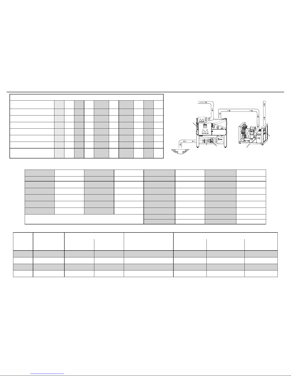
Physical Characteristics
Master Controller
Assembly
Tanks Typical V3, V5 or V7 System Pump Configurations
MT10 / MT12
10 Gallon
CT20 / CT22
Continuum
MT10 / MT12 Tank Stacked
onto One V3, V5 or V7 Pump
One V3, V5 or V7
Pump
Two V3, V5 or V7
Pumps Stacked
Three
V5 Pumps Stacked
Width
13.5 in. (34 cm) 29 in. (74 cm) 25 in. (64 cm) 29 in. (74 cm) 25 in. (64 cm) 25 in. (64 cm) 25 in. (64 cm)
Depth 3 in. (8 cm) 22 in. (56 cm) 23 in. (58 cm) 23 in. (58 cm) 21 in. (53 cm) 21 in. (53 cm) 21 in. (53 cm)
Height 11 in. (28 cm) 33 in. (84 cm) 50 in. (127 cm) 50 in. (127 cm) 17 in. (43 cm) 34 in. (86 cm) 51 in. (130 cm)
Weight
13 Lbs. (6 kg) 75 Lbs. (34 kg) 150 Lbs. (68 kg) 220 Lbs. (100 kg) 145 Lbs. (66 kg) 290 Lbs. (132 kg) 435 Lbs. (197 kg)
MOJAVE SYSTEM CONFIGURATIONS
Gas/Liquids/
Solids
From
Treatment
Room
Exhaust to
Outside Vent
V3, V5 or V7
Vacuum Pump
Heat
Exchanger
Gate
Valve
Check
Valve
Sewer
Drain
MT10
Separator
Tank
Gas
Typical MOJAVE System Installation
Liquids/Solids
System Components
V3 V5 V7 2V3 2V3CT 2V5 2V5CT 2V7 3V5 4V5
V3 Pump Assembly 1 0 0 2 2 0 0 0 0 0
V5 Pump Assembly 0 1 0 0 0 2 2 0 3 4
V7 Pump Assembly 0 0 1 0 0 0 0 2 0 0
MT10 / MT12 Tank Assembly 1 1 1 1 0 1 0 0 0 0
CT20 / CT22 Tank Assembly 0 0 0 0 1 0 1 1 1 1
Master Controller Assembly 1 1 1 1 1 1 1 1 1 1
Maximum Users 3 5 7 6 6 10 10 14 15 20
Recommended Number of Simultaneous HVE/SE Users
V3 V5 V7 2V3 or 2V3CT 2V5 or 2V5CT 2V7 3V5 4V5
HVE SE HVE SE HVE SE HVE SE HVE SE HVE SE HVE SE HVE SE
3
+ 0
5
+ 0
7
+ 0
6
+ 0
10
+ 0
14
+ 0
15
+ 0
20
+ 0
2 + 2 4 + 2 6 + 2 5 + 2 9 + 2 13 + 2 14 + 2 18 + 4
0 + 6 2 + 6 5 + 4 3 + 6 7 + 6 12 + 4 12 + 6 13 + 14
0 + 10 4 + 6 1 + 10 5 + 10 9 + 10 9 + 12 10 + 20
0 + 14 0 + 12 3 + 14 6 + 16 6 + 18 8 + 24
Note: 1 HVE = 2 SE’s
1 HVE = 2 Nitrous Scavengers
1 + 18 2 + 24 2 + 26 5 + 30
0 + 20 0 + 28 0 + 30 0 + 40
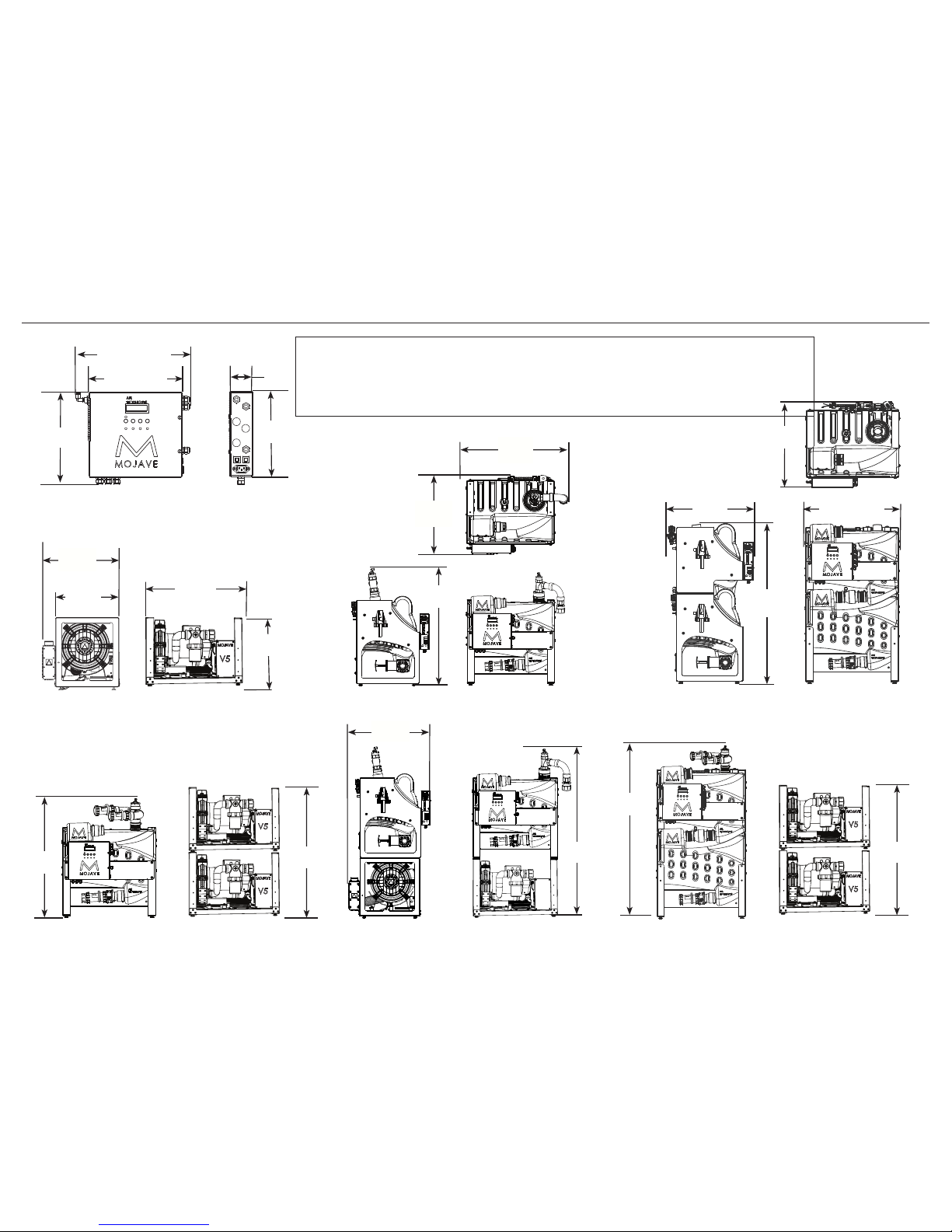
Important:
The Master Controller is mounted on the front of the MT10 / MT12 or CT20 / CT22 tank chassis.
Never stack a CT20 /CT22 Tank on top of any Pump. Never stack a Pump on top of any Tank.
Recommend pumps only be stacked a maximum of two high.
All units shipped with all leveling feet set to lowest position.
11 in.
(28 cm)
Master Controller Assembly Dimensions
10 in.
(24 cm)
11 in. (28 cm)
13.5 in. (34 cm)
3 in.
(8 cm)
V3, V5 and V7 Vacuum Pump Dimensions
17 in.
(43 cm)
25 in.
(64 cm)
21 in.
(53 cm)
17.5 in.
(44 cm)
2V3 or 2V5 System Installation
Recommended Stacked Pumps with Tank on Side
33 in.
(84 cm)
34 in.
(86 cm)
V3, V5 and V7 System Dimensions
23 in.
(58 cm)
50 in.
(127 cm)
2V7, 2V3CT or 2V5CT System Installation
Recommended Stacked Pumps with CT20 / CT22 Tank on Side
34 in.
(86 cm)
50 in.
(127 cm)
MT10 / MT12 10 Gallon Tank Dimensions
22 in.
(56 cm)
29 in.
(74 cm)
33 in.
(84 cm)
ASSEMBLY DIMENSIONS
CT20 / CT22 Continuum Tank Dimensions
42 in.
(107 cm)
25 in. (64 cm)
23 in.
(58 cm)
23 in.
(58 cm)
 Loading...