

Systemkonvektor
System Convector
WSK 180
WSK 260
WSK 320
WSK 410
HANDBUCH
USER MANUAL
WSK 260

2
INHALT
Inhaltsverzeichnis..............................................................2
Übersicht............................................................................3
Produktbeschreibung .....................................................3
Sicherheitshinweise.........................................................3
Einbauanleitung ................................................................4
Lieferumfang...................................................................4
Einbausituation...............................................................4
Montageabdeckung .......................................................5
Systemzubehör..................................................................6
Höhenjustierung .............................................................6
Anschlussgarnitur............................................................7
Thermische Regelung........................................................8
Fernsteller FST 2/5 ...........................................................8
Elektrische Regelung.........................................................9
Alpha-Antrieb AA 2001 ..................................................9
Anschlussdose tA 23........................................................9
Alpha-Regler AR2010 KD/ AR 2010 CD........................10
Alpha-Leistungsmodul ALM 22....................................10
Elektrische Regelung Anschlussplan............................11
Designrollrost ..................................................................12
Designrollrostsicherung (Optional)..............................12
Systemerweiterungen ....................................................13
Systemverbinder............................................................13
Gehrungspassung..........................................................13
Anhang ............................................................................14
Wartungshinweis ..........................................................14
Urheberrecht.................................................................15
Kontakt ............................................................................16
CONTENT
Content ..............................................................................2
Introduction.......................................................................3
Product description.........................................................3
Safety instructions ..........................................................3
Instructions for installation ..............................................4
Scope of supply...............................................................4
Method of installation ...................................................4
Protective cover ..............................................................5
System accessoiries ...........................................................6
Height adjustment block................................................6
Connection kit.................................................................7
Thermal Control ................................................................8
Thermic remote control unit FST 2/5 .............................8
Electrical control - components........................................9
Alpha-Actuator AA 2000 ................................................9
Connection box tA 23.....................................................9
Alpha-Thermostat AR 2010S-S / AR 2010C-S ...............10
Alpha-Power module ALM 22......................................10
Electrical control - connecting diagram .........................11
Decorative Roll-up Grill ..................................................12
Decorative Roll-up Grill Guard (optional) ...................12
System extensions ..........................................................13
System connectors ........................................................13
Mitred joint...................................................................13
Appendix .........................................................................14
Maintenance instructions.............................................14
Copyright notice ...........................................................15
Contact.............................................................................16
Inhalt / Content
WSK 180 / WSK 260 / WSK 320 / WSK 410
3
Sicherheitshinweise / Safety instructions
Infosymbole / infosysmbols
Sehr geehrter Monteur!
Systemkonvektoren für den Einbau im Fußbodenbereich (Estrichhöhe) können vor Fensterfronten je nach
gewählter Vorlauftemperatur zur Kaltluftabschirmung (WSK 180 / WSK 260 / WSK 320 / WSK 410) oder als
Vollheizung (WSK 320 / WSK 410) dienen. Sie werden mit zweirohrigen Heizelementen (WSK 180 / WSK 260),
dreirohrigen Heizelementen (WSK 320) oder vierrohrigen Heizelementen (WSK 410) mit einer Gerätehöhe von
90 mm,110 mm, 140 mm bzw. 190 mm gefertigt. (WSK 410 nur in den Höhen 90 mm und 110 mm.)
Lesen Sie bitte zunächst aufmerksam dieses Handbuch, bevor Sie mit dem Einbau des Systemkonvektors in den Estrich, dem Rohrleitungsanschluss oder der elektrischen Verdrahtung beginnen. Dieses
Handbuch enthält zudem wichtige Wartungshinweise. Übergeben Sie daher das Handbuch dem späteren Nutzer
als Revisionsunterlage.
Prüfzeichen / mark of conformity
Systemkonvektoren sind qualitativ hochwertige Geräte, die nach
Bestellung millimetergenau gefertigt und durch Verpackung gegen
äußere Beschädigung geschützt wurden.
Für Schäden, die auf unsachgemäße oder den im Handbuch genannten
Hinweisen zuwiderlaufende Behandlung zurückzuführen sind, haftet
der Hersteller nicht.
Die Elektroinstallation muss nach den aktuell gültigen nationalen
Bestimmungen für Elektroinstallationen (VDE 0100) von einer
autorisierten Fachkraft durchgeführt werden. Das Öffnen des Gerätes
ist nur durch eine autorisierte Fachkraft und im spannungsfreien Zustand
zulässig.
Dear valued Installer!
System Convectors for the installation in the floor area (floor paving level), located in front of window surfaces,
can serve as a barrier against cold air (WSK 180 / WSK 260 / WSK 320 / WSK 410) or as complete room heating
system
(WSK 320 / WSK 410), depending on the chosen inlet temperature. They are manufactured with two-tube
heating elements (WSK180 / WSK 260), three-tube heating elements (WSK 320) or four-tube heating elements
(WSK 410), with a unit height of 90 mm, 110 mm, 140 mm and 190 mm. (WSK 410 with a unit height of 90 mm
and 110 mm only.)
Please read these instructions carefully prior to installing the fan-assisted System Convector into the floor
paving, connecting the tubing or connecting the electrical wiring. This manual contains also important
maintenance notes. Please hand over this manual to the later user for revision purposes.
System Convectors are high quality devices which after ordering are
manufactured to the millimetre and protected against outer damage by
appropriate packing. The manufacturer is not liable for damages which
can be put down to inappropriate treatment or treatment against the
indications given in the manual.
The electrical installation must be performed by an authorised
specialist and according to the valid national regulations as well
as according to the regulations of the local power supply companies.
Opening the unit is only permitted by a qualyfied specialist and the unit
has to be disconnected from the mains.
Wichtiger Hinweis,
bitte unbedingt beachten.
Important note,
must be implicity observed
Anlage spannungsfrei
schalten.
Disconnect the system from
the mains.
Produktbeschreibung / Product description
WSK 180 / WSK 260 / WSK 320 / WSK 410
Übersicht / Introduction
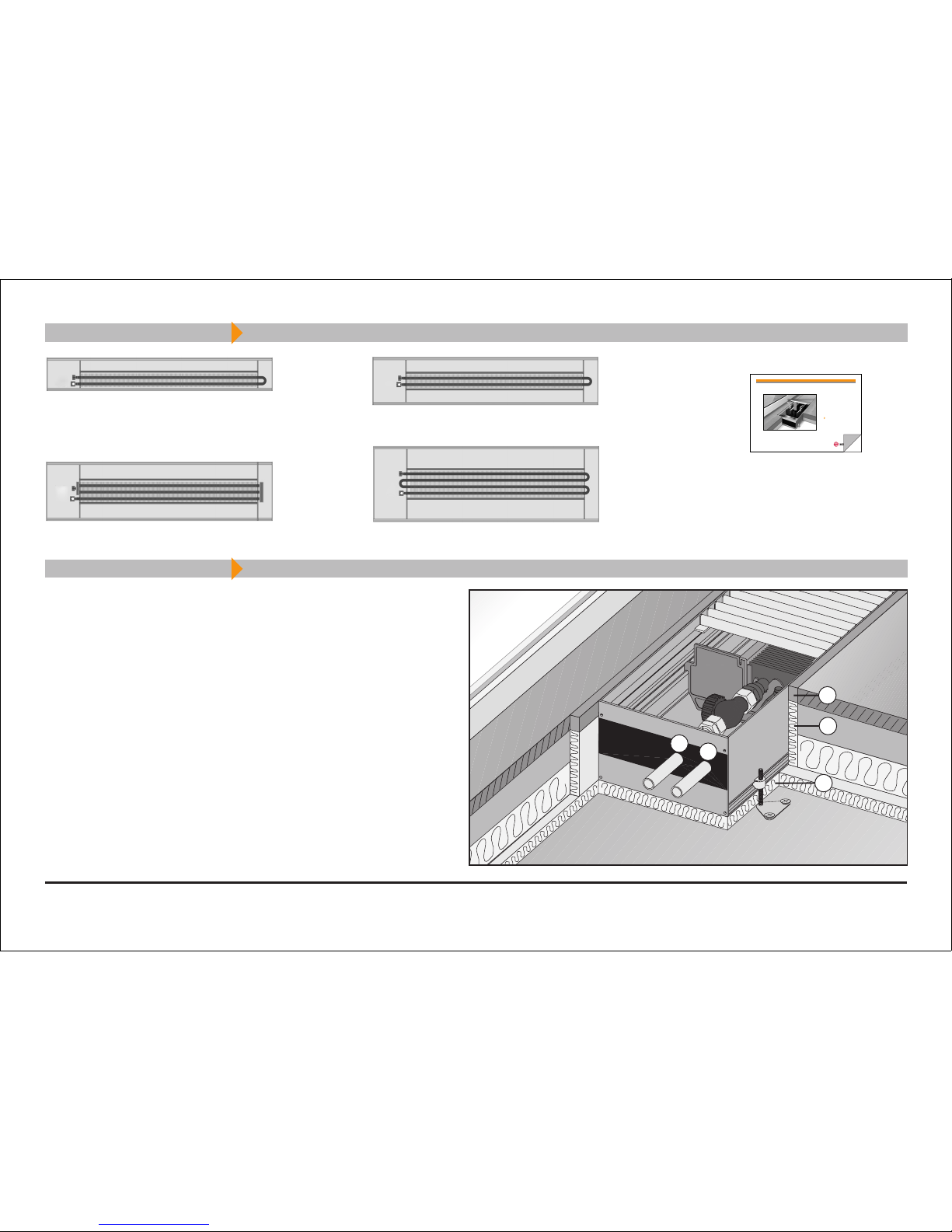
Einbausituation / Method of installation
4
1. Dauerelastische Randstreifen
2. Randschalldämmung
3. Trittschalldämmung
Bitte beachten Sie die Fensterseite!
Der Rohrleitungsanschluss erfolgt serienmäßig an der linken
Stirnseite, der Elektroanschluss befindet sich ebenfals links.
(Sonderanschlüsse sind auf Anfrage möglich.)
1. Continuously elastic border strips
2. Border acoustic insulation
3. Step-on acoustic insulation
Please observe the window side!
In series, the tube connection is performed on the left front side,
the electrical connection is also on the left side.
(Special connections are available on request.)
Lieferumfang / Scope of supply
Handbuch
User manual
V
R
1
2
3
Fensterseite
/ window side
Systemkonvektor WSK 320
System Convector WSK 320
Systemkonvektor WSK 260
System Convector WSK 260
Systemkonvektor WSK 180
System Convector WSK 180
Systemkonvektor WSK 410
System Convector WSK 410
WSK 180 / WSK 260 / WSK 320 / WSK 410
Einbauanleitung / Instructions of installations
Systemkonvektor
System Convector
WSK 180
WSK 260
WSK 320
WSK 410
HANDBUCH
USER MANUAL
WSK 260
5
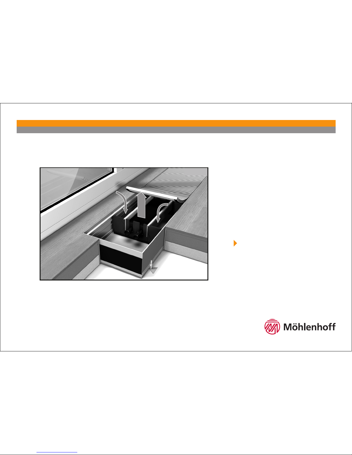
Montageabedeckung / Protective cover
Entfernen Sie die Montageabdeckung dauerhaft erst nach erfolgtem Einbau des Systemkonvektors
und dem Abschluss der Baumaßnahmen. Sie verhindern so die Verschmutzung bzw. die Beschädigung
des Systemkonvektors.
Die Rohrleitungsanschlussseite ist auf der Montageabdeckung mit einem "
"gekennzeichnet.
Remove the protective cover permanently only after finishing the installation of the System Convector
and after finishing all building work. By this you avoid contamination and damage to the System
Convector.
The tube connection side is marked with "
" on the protective cover.
WSK 180 / WSK 260 / WSK 320 / WSK 410
6
Höhenjustierung / Height adjustment block
Systemzubehör / System accessoiries
JBI 8.80 (height: 80 mm) Allen size 4
JBI 8.80 (высота: 80 мм) шестигранный торцовый ключ разм. 4
JB 8.80 (height: 80 mm) Allen size 4
JB 8.80 (высота: 80 мм) шестигранный торцовый ключ разм. 4
Innenliegende Justierblöcke
Für direkt-angrenzte Objektmontage (z.B. Fenster/Fassaden) kann der Systemkonvektor mit
innenliegenden Justierblöcken ausgestattet worden sein.
Interior adjustment blocks
For an installation with direct contact to other objects (e. g. windows/facades) the system
convector may have been equipped with interior adjustment blocks.
Aussenliegende Justierblöcke
Die aussenliegenden Justierblöcke können einfach und per Hand in die dafür vorgesehene
Arretierungsleiste entlang des Konvektors angebracht werden.
Exterior adjustment blocks
The exterior adjustment blocks can be attached easily and manually to the locking strip for this
purpose, located along the convector.
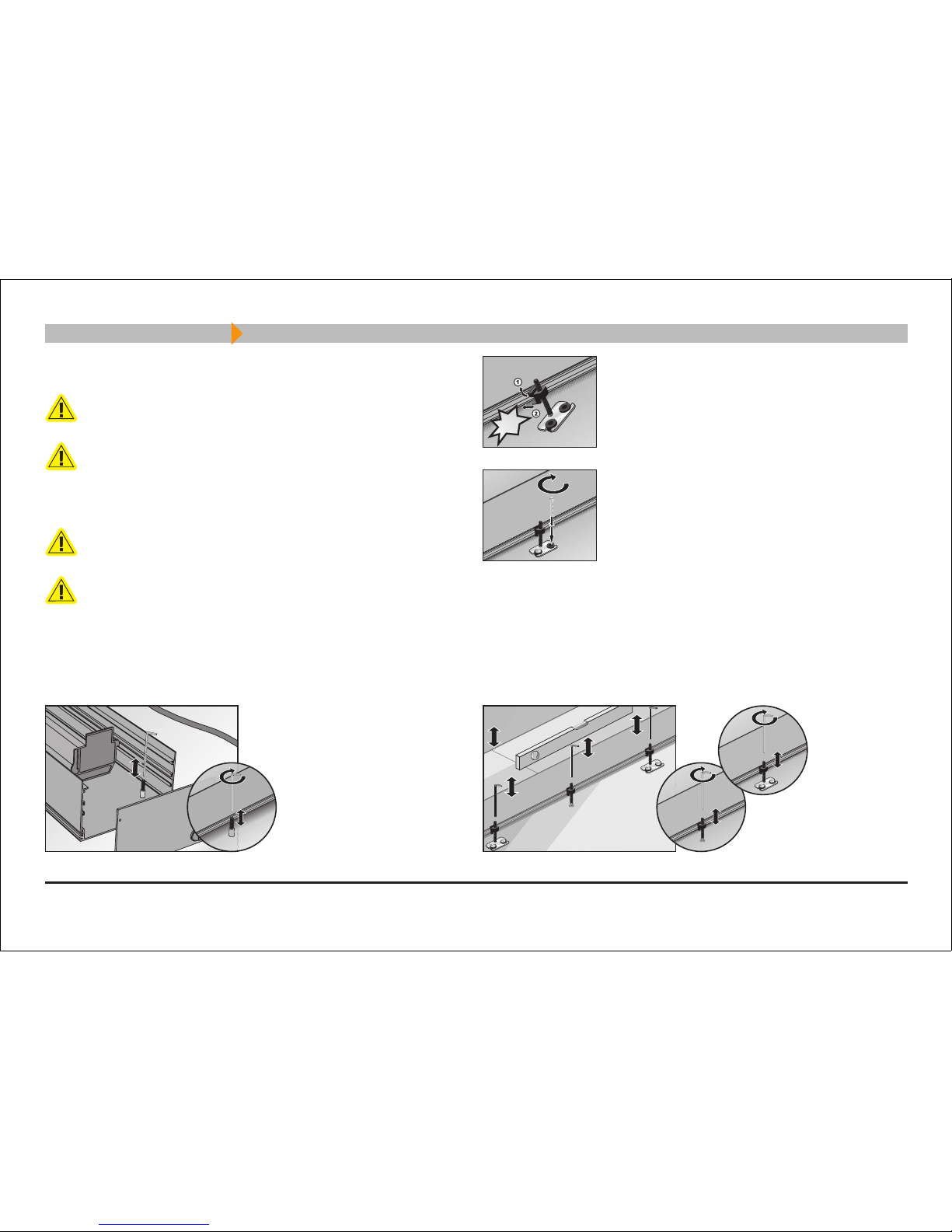
Locking of the adjustment blocks in the lateral profile of
the trough:
The engagement of the adjustment blocks must be
clearly audible.
Fixing in raw floor with cylinder head screw
Ø 4.05.5 mm and washer Ø 15 - 18 mm (DIN 9021)
KLACK!
Arretierung der Justierblöcke im Seitenprofil der Mulde:
Einrasten der Justierblöcke muss deutlich hörbar sein.
Befestigung im Rohfußboden mit Zylinderkopfschraube
Ø 4,0 - 5,5 mm und Unterlegscheibe Ø 15 - 18 mm (DIN
9021)
Positionierung und Ausrichtung
Justierblöcke dienen zur Ausrichtung der Elektro-Systemkonvektoren und auch zum Schutz
gegen das Aufschwimmen während der Einbringung des Estrichs.
Standardausführung:
Unterfüttern Sie den Systemkonvektor unbedingt mit einem druckfesten Füllstoff bzw.
einer Wärme- und Trittschalldämmung, um eine volle Begehbarkeit zu erreichen. Die
im Lieferumfang enthaltenen Justierblöcke sind nur zur Nivellierung vorgesehen!
Freibegehbare Ausführung:
Durch beidseitige Anordnung innen oder außen liegender Justrierblöcke alle 500 mm
ist eine Freibegehbarkeit für bis zu 120 kg gegeben.
Positioning and alignment
Adjustment blocks serve for the levelling of the system convectors and also for protecting against
upward movement during the floor pavement installation.
Standard design:
It is very important to support the system convector with a pressure-resistant filling
matter or with a heat/step-on acoustic insulation in order to obtain full step-on ability.
The adjustment blocks included in the scope of delivery are only intended for levelling
purposes!
Design for free step-on:
Due to the arrangement of interior or exterior adjustment blocks on both sides each
500 mm, free step-on ability is ensured for up to 120 kg.
WSK 180 / WSK 260 / WSK 320 / WSK 410
WSK 180 / WSK 260 / WSK 320 / WSK 410
7
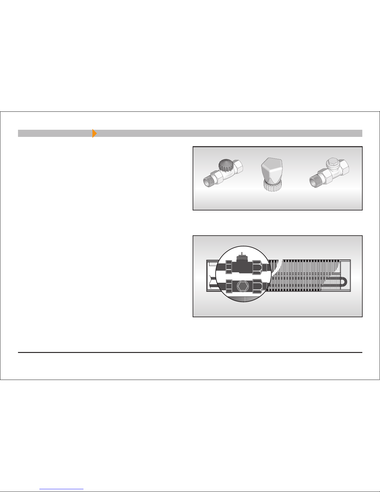
VUD 15 Thermostat-Ventilunterteil Durchgangsform DN15
HR Handregulierkappe für VUD 15
RLD 15 Regulux-Rücklaufverschraubung Durchgangsform
VUD 15 Thermostat valve bottom passage from DN15
HR Manuel regulation cap for VUD 15
RLD 15 Regulux screwed return connection passage for DN 15
Anschlussgarnitur / Connection kit
Schrauben Sie das VUD 15 in den Heizungs-Vorlauf (Fensterseite) und
das RLD 15 in den Heizungs-Rücklauf (Raumseite). An dieser Garnitur
muss der Rohrleitungsanschluss erfolgen.
Screw the VUD 15 into the heating flow (window side) and the RLD 15
into the heating backflow (room side). The tube connection must be
performed at these fittings.
VUD 15
RLD 15
RLD 15HRVUD 15

Externer Fernsteller / Thermal remote control unit
FST 2/5
Der FST 2/5 ist ein flüssigkeitsgefüllter Thermostat mit 2 oder 5 m Kapillarrohr und einem einstellbaren
Sollwertbereich von 8 bis 27 °C.
FST 2/5
The FST 2/5 is a liquid-filled thermostat with capillary tube 2 or 5 metres long. The range of adjustment:
8 °C to 27 °C.
8
Thermische Regelung Komponenten / Thermal control components
Thermische Regelung Anschlussplan / Thermal control connecting diagram
FST 2/5
Verwenden Sie zur Verlegung des Kapillarrohrs ein Leerrohr mit einem
Durchmesser Ø min. 23 mm.
Die Installation des Fernstellers muss
auf einer Unterputzdose erfolgen.
FST 2/5
For installing the capillary tube use a blank tube, Ø 23 mm, min.
The thermal control unit has to be installed
to an installation socket.
ca.1500mm
1
WSK 180 / WSK 260 / WSK 320 / WSK 410
9
Elektrische Regelung Komponenten / Electrical control components
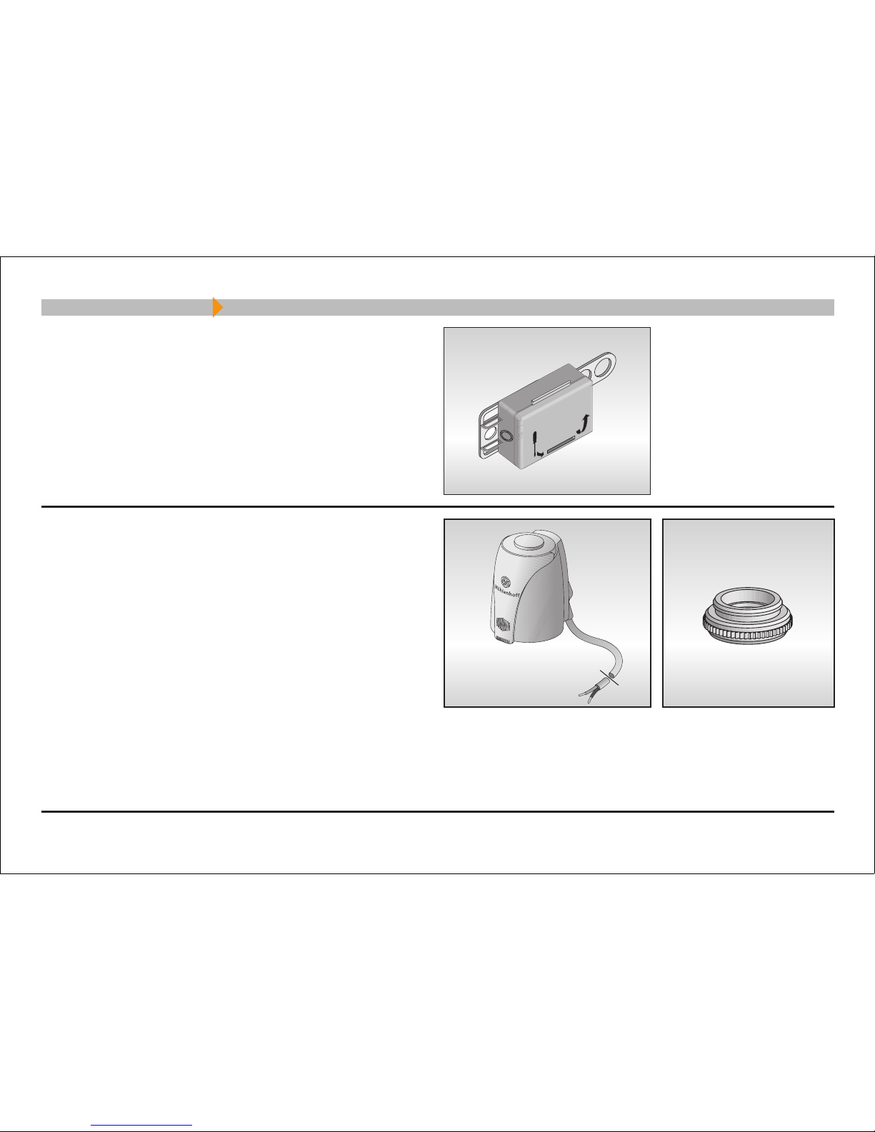
Alpha-Antrieb 230V
AA 2000-80-02
Thermoelektrischer Stellantrieb in der Version stromlos geschlossen
inklusive Ventiladapter VA 80, passend zu VUD 15.
Bitte beachten Sie vor dem Aufstecken des Alpha-Antriebes auf das
Ventil-Unterteil VUD 15 die Installationsanleitung des Alpha-Antriebes.
Führen Sie die Anschlussleitung in die Anschlussdose tA23 ein, und
verbinden Sie diese mit der vom Alpha-Regler kommenden Leitung
mittels vorhandener Lüsterklemme.
Alpha-Actuator 230V
AA 2000-80-02
Thermoelectric actuator in the version normally closed, including valve
adapter VA 80, matching VUD 15.
Before connecting the Alpha-Actuator to the valve bottom VUD 15,
please observe the installation instruction of the Alpha-Actuator.
Lead the connecting line into the connection box tA23 and connect it
to the line coming from the Alpha-Thermostat, using the supplied
insulating screw joint.
Anschlussdose tA 23
Anschlussdose für Alpha-Antrieb und Alpha-Regler. Klicken Sie die
tA23 in das Seitenprofil der Konvektormulde in Nähe vom VUD 15
ein.
Connection box tA 23
Connection box for connecting Alpha-Actuators with Alpha-Thermostats.
Simply install through clip-on attachment on profil rails close to the
VUD 15.
WSK 180 / WSK 260 / WSK 320 / WSK 410

WSK 180 / WSK 260 / WSK 320 / WSK 410
10
Elektrische Regelung Komponenten / Electrical control components
Alpha-Regler / Alpha-Thermostat
AR 2010S-S / AR 2010C-S inkl. Alpha-Systemsockel
Raumtemperaturregler für den Anschluss von max. 5 Alpha-Antrieben.
Automatische Temperaturabsenkung um 4 K.
Nur AR 2010C-S: Schaltkugel zur Wahl der Betriebsart Temperaturabsenkung.
Controler als steckfertige Digitaluhr zur Handprogrammierung der Absenkzeiten.
Die Installation des Alpha-Systemsockels muss auf einer Unterputzdose erfolgen.
Bitte beachten Sie auch die Installationsanleitung des Alpha-Reglers.
AR 2010S-S / AR 2010C-S incl. Alpha-Mounting Base
Roomthermostat that allowes a connecting of 5 Alpha-Actuators, max.
Automatic temperature setback of 4 K.
Only AR 2010C-S:Selector switch for operation mode selection of temperature setback mode.
Plug-in digital control clock for manual programming of setback times.
The Alpha-Mounting base must be installed onto a flush-type electrical box.
Please observe the notes in the installation and operating instructions of the Alpha-Thermostat.
AR 2010S-S
AR 2010C-S
ALM 22
Alpha-Leistungsmodul / Alpha-Power Module
ALM 22
Leistungsmodul zum Anstecken an den Alpha-Systemsockel für den Anschluss
von max. 10 Alpha-Antrieben oder einer ohmschen Last von max. 1200 VA (5 A).
ALM 22
Power Module can be plugged to the Alpha-Mounting Base and allows a connection
of 10 Alpha-Actuators, max. or of an ohmic load of 1200 VA (5 A), max.

Elektrische Regelung Anschlussplan / Electrical control connecting diagram
Alpha-Regler AR 2010S-S oder AR 2010C-S
Die Installation des Alpha-Systemsockels muss auf einer
Unterputzdose erfolgen.
Bitte beachten Sie die Hinweise in der Installations- und Bedienungsanleitung des Alpha-Reglers.
Die Elektroinstallation muss nach den aktuell gültigen nationalen
Bestimmungen für Elektroinstallationen (VDE 0100) von einer
autorisierten Fachkraft durchgeführt werden.
Alpha-Thermostat AR 2010S-S or AR 2010C-S
The Alpha-Mounting Base must be installed onto a flush-type
electrical box. Please observe the notes in the installation and
operating instructions of the Alpha-Thermostat.
The electrical installation must be performed by an authorised
specialist and according to the valid national regulations as well
according to the regulations of the local power supply companies.
11
AR 2010C-SAR 2010S-S
3 x 1.5
4
3
1
2
3 x 1.5
3 x 1.5
WSK 180
1. Anschlussdose tA23
2. Alpha-Antrieb
3. Netzzuleitung
4. Gegebenfalls Ableitung zu weiteren WSK
1. Connection box tA23
2. Alpha-Actuator
3. Mains connection line
4. If necessary, branches to other WSK
WSK 180 / WSK 260 / WSK 320 / WSK 410

WSK 180 / WSK 260 / WSK 320 / WSK 410
Designrollrost / Decorative Roll-up Grill
Designrollrost / Decorative Roll-up Grill
Designrollrostsicherung (Optional)
Die Designrollrostsicherung dient zum Schutz vor dem Hineingreifen in den Systemkonvektor.
Fügen Sie die Sicherung so zwischen die Roststäbe, dass sich der Befestigungsstab der Sicherung über
und dessen Befestigungslaschen sich unter den Roststabverbindern (gummierte Trittschalldämmung)
befinden.
WSK 260 / WSK 320 / WSK 410 - Trennen Sie vor dem Einbau der Sicherung in den Designrollrost
der die Rollrostverbinder in der Mitte!
Legen Sie den Designrollrost in die Systemkonvektormulde. Schieben Sie mittels eines Inbussteckschlüssels
(Größe 3) die Befestigungsschrauben nach außen und somit die Befestigungslaschen unter die Auflagen
der Mulde für den Designrollrost. Drehen Sie abschließend die Schrauben fest.
Decorative Roll-up Grill Guard
(optional)
The Decorative Roll-up Grill Guard secures Decorative Roll-up Grill against lifting.
Position the guard between the ribs in a way that the fixing rod of the guard is located above the guard
and the fixing lugs of the rod are located below the grill rod connectors (rubberized step-on acoustic
insulation).
WSK 260 / WSK 320 / WSK 410 Separate the rolle-up grill connectors in the centre before
installing the guard into the Decorative Roll-up Grill!
Insert the Decorative Roll-up Grill into the System Convector trough. Using an allen key (size 3), push
the fixing screws to the outside, and thus, the fixing lugs underneath the support rail of the trough for
the grill. Finally, tighten the screws.
CombiCut
WSK 260 / WSK 320 /
WSK 410
12

WSK 180 / WSK 260 / WSK 320 / WSK 410
Systemerweiterungen / System extensions
Systemverbinder
SV Systemverbinder dienen zur Verbindung
zweier Systemkonvektormulden bzw. zweier
Konvektorteile.
Schieben Sie die Verbinder vermittelnd in die Nuten
der Konvektormulde.Fügen Sie die Konvektorteile
passend zusammen und fixieren Sie die Verbindung
mittels Madenschrauben M6 Inneninbus Gr. 3.
Gehrungspassung
GPW Gehrungspassung
Systemkonvektorteile auf Gehrung werden
steckfertig geliefert.
Stecken Sie die Konvektorteile zusammen und
verbinden Sie diese mit Hilfe der Systemverbinder SV.
Verbinden Sie die Heizelemente durch die der Lieferung
beiliegenden Winkelverbinder.
GPS Wie zuvor, jedoch ohne Winkelverbindung
der Heizelelemente.
System connectors
SV System connectors serve for connecting two
System Convector troughs, or two convector
parts, respectively.
Push the connectors in even distances into the grooves
of the convector trough. Fix the convector parts and
fix the connection by means of stud screws M6, allen
key size 3.
Mitred joint
GPW Mitred joint
Angles and length of mitred joints for System
Convector parts are delivered ready-to-plug-in.
Fit the convector parts together and connect them by
means of the system connectors SV. Connect the heating
elements by means of the supplied angled connectors.
GPS As done before, but without angled connectors
of heating elements.
13

14
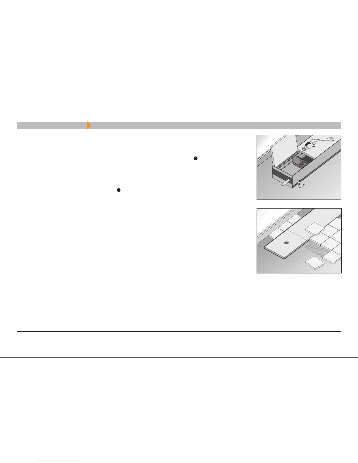
Wartungshinweis / Maintenance instructions
WSK 180 / WSK 260 / WSK 320 / WSK 410
Anhang / Appendix
Sehr geehrter Kunde!
Durch Luftzirkulation kann es im Bereich des Heizelementes zur Staubablagerung kommen.
Lösen Sie, falls der Konvektor über eine Rollrostsicherung verfügt, wie in der Darstellung ersichtlich, die
Sicherung des Designrollrostes, und rollen Sie den Rost gleichmäßig ohne ihn zu knicken auf.
Das Heizelement könnte heiß sein! Schalten Sie bei Wartungsarbeiten unbedingt Regler und
Systemkonvektor spannungsfrei!
Mit einem Staubsauger können Sie den Staub zwischen den Heizelementlamellen und aus der
Systemkonvektormulde entfernen.
Vergessen Sie nicht, den Designrollrost wieder zu sichern!
Lassen Sie Reparaturen an der elektrischen Regelung nur von einer autorisierten Fachkraft durchführen!
Das Öffnen des Gerätes ist nur im spannungsfreien Zustand zulässig!
Dear customer!
Due to the air circulation, dust may deposit in the area of the heating element.
As shown in the figure, if you have installated a Decorative Roll-up Grill Guard, loosen the Decorative
Roll-up Grill Guard and roll up the grill evenly without bending it.
The heating element could be hot! It is very important to de-energise the thermostat and system
convector during maintenance work!
You can remove the dust between the heating element lamina and from the System Convector trough
by means of an vacuum cleaner.
Do not forget to secure the Decorative Roll-up Grill!
Have repairs at the electric control only performed by an authorised specialist!
Before opening the unit it has be disconnected from the mains.

WSK 180 / WSK 260 / WSK 320 / WSK 410
Urheberrechtshinweis / Copyright Notice
Urherberrechtshinweis
Dieses Handbuch ist urheberrechtlich geschützt. Alle Rechte vorbehalten.
Es darf weder ganz noch teilweise ohne vorheriges Einverständnis von
Möhlenhoff Wärmetechnik GmbH kopiert, reproduziert, gekürzt oder
in irgendeiner Form übertragen werden, weder mechanisch noch
elektronisch. Die zugrunde liegende Information wurde sorgfältig geprüft
und nach bestem Wissen zusammengestellt. Dennoch kann Möhlenhoff
Wärmetechnik keinerlei Haftung für etwaige Fehler übernehmen, die
in diesem Handbuch enthalten sein könnten. In keinem Fall kann
Möhlenhoff Wärmetechnik zu Ersatzleistungen für Schäden (direkte,
indirekte, spezielle) oder Neben- und Folgeschäden herangezogen
werden, die sich aus einem Fehler oder einer Auslassung in diesem
Handbuch ergeben, selbst wenn die Möglichkeit eines solchen Schadens
bereits aufgezeigt wurde.
Im Interesse einer fortlaufenden Produktentwicklung behält sich
Möhlenhoff Wärmetechnik das Recht vor, dieses Handbuch und die
beschriebenen Produkte ohne Vorankündigung oder Verpflichtung
jederzeit zu verbessern.
© Copyright 2005
Möhlenhoff Wärmetechnik GmbH
Museumstrasse 54a
38229 Salzgitter / Salder
Germany
Copyright Notice
This manual is copyrighted. All rights reserved. This document may not,
in whole or part, be copied, reproduced, reduced or translated by any
means, either mechanical or electronic, without prior consent in writing
from Möhlenhoff Wärmetechnik GmbH. The information in this manual
has been carefully checked and is believed to be accurate. However,
Möhlenhoff Wärmetechnik assumes no responsibility for any inaccuracies
that may be contained in this manual. In no event will Möhlenhoff
Wärmetechnik be liable for direct, indirect, special, incidental or
consequential damages re-sulting from any defect or omission in this
manual, even if advised of the possibility of such damages.
In the interest of continued product development, Möhlenhoff
Wärmetechnik reserves the right to make improvements in this manual
and the products it describes at any time, without notice or obligation.
© Copyright 2005
Möhlenhoff Wärmetechnik GmbH
Museumstraße 54 a
38229 Salzgitter
Germany
15
Technische Änderungen vorbehalten. These instruction may be subject to technical alterations.
SYSTEMKONVEKTOREN
SYSTEM CONVECTORS
8-D21-45-005 Rev 1.1
Alpha-Regler /
Alpha-Thermostat
Designrollrost /
Decorative Roll-up Grill
Systemkonvektoren /
System Convectors
Alpha-Basis /
Alpha-Basis
Alpha-Antrieb /
Alpha-Actuator
Postfach / p/o-box:
Postfach 100525
D-38205 Salzgitter
Germany
Adresse / Address:
Museumstrasse 54a
D-38229 Salzgitter
Germany
Telefon +49 53 41 · 84 75-0
Telefax +49 53 41 · 84 75-99
email: contact@moehlenhoff.de
Internet: www.moehlenhoff.com
WSK 180 / WSK 260 / WSK 320 / WSK 410
 Loading...