

Mohlenhoff WSK 180, WSK 410, WSK 320, WSK 260 User Manual
Systemkonvektor
System Convector
WSK 180
WSK 260
WSK 320
WSK 410
HANDBUCH
USER MANUAL
WSK 260

2
INHALT
Inhaltsverzeichnis..............................................................2
Übersicht............................................................................3
Produktbeschreibung .....................................................3
Sicherheitshinweise.........................................................3
Einbauanleitung ................................................................4
Lieferumfang...................................................................4
Einbausituation...............................................................4
Montageabdeckung .......................................................5
Systemzubehör..................................................................6
Höhenjustierung .............................................................6
Anschlussgarnitur............................................................7
Thermische Regelung........................................................8
Fernsteller FST 2/5 ...........................................................8
Elektrische Regelung.........................................................9
Alpha-Antrieb AA 2001 ..................................................9
Anschlussdose tA 23........................................................9
Alpha-Regler AR2010 KD/ AR 2010 CD........................10
Alpha-Leistungsmodul ALM 22....................................10
Elektrische Regelung Anschlussplan............................11
Designrollrost ..................................................................12
Designrollrostsicherung (Optional)..............................12
Systemerweiterungen ....................................................13
Systemverbinder............................................................13
Gehrungspassung..........................................................13
Anhang ............................................................................14
Wartungshinweis ..........................................................14
Urheberrecht.................................................................15
Kontakt ............................................................................16
CONTENT
Content ..............................................................................2
Introduction.......................................................................3
Product description.........................................................3
Safety instructions ..........................................................3
Instructions for installation ..............................................4
Scope of supply...............................................................4
Method of installation ...................................................4
Protective cover ..............................................................5
System accessoiries ...........................................................6
Height adjustment block................................................6
Connection kit.................................................................7
Thermal Control ................................................................8
Thermic remote control unit FST 2/5 .............................8
Electrical control - components........................................9
Alpha-Actuator AA 2000 ................................................9
Connection box tA 23.....................................................9
Alpha-Thermostat AR 2010S-S / AR 2010C-S ...............10
Alpha-Power module ALM 22......................................10
Electrical control - connecting diagram .........................11
Decorative Roll-up Grill ..................................................12
Decorative Roll-up Grill Guard (optional) ...................12
System extensions ..........................................................13
System connectors ........................................................13
Mitred joint...................................................................13
Appendix .........................................................................14
Maintenance instructions.............................................14
Copyright notice ...........................................................15
Contact.............................................................................16
Inhalt / Content
WSK 180 / WSK 260 / WSK 320 / WSK 410
3
Sicherheitshinweise / Safety instructions
Infosymbole / infosysmbols
Sehr geehrter Monteur!
Systemkonvektoren für den Einbau im Fußbodenbereich (Estrichhöhe) können vor Fensterfronten je nach
gewählter Vorlauftemperatur zur Kaltluftabschirmung (WSK 180 / WSK 260 / WSK 320 / WSK 410) oder als
Vollheizung (WSK 320 / WSK 410) dienen. Sie werden mit zweirohrigen Heizelementen (WSK 180 / WSK 260),
dreirohrigen Heizelementen (WSK 320) oder vierrohrigen Heizelementen (WSK 410) mit einer Gerätehöhe von
90 mm,110 mm, 140 mm bzw. 190 mm gefertigt. (WSK 410 nur in den Höhen 90 mm und 110 mm.)
Lesen Sie bitte zunächst aufmerksam dieses Handbuch, bevor Sie mit dem Einbau des Systemkonvektors in den Estrich, dem Rohrleitungsanschluss oder der elektrischen Verdrahtung beginnen. Dieses
Handbuch enthält zudem wichtige Wartungshinweise. Übergeben Sie daher das Handbuch dem späteren Nutzer
als Revisionsunterlage.
Prüfzeichen / mark of conformity
Systemkonvektoren sind qualitativ hochwertige Geräte, die nach
Bestellung millimetergenau gefertigt und durch Verpackung gegen
äußere Beschädigung geschützt wurden.
Für Schäden, die auf unsachgemäße oder den im Handbuch genannten
Hinweisen zuwiderlaufende Behandlung zurückzuführen sind, haftet
der Hersteller nicht.
Die Elektroinstallation muss nach den aktuell gültigen nationalen
Bestimmungen für Elektroinstallationen (VDE 0100) von einer
autorisierten Fachkraft durchgeführt werden. Das Öffnen des Gerätes
ist nur durch eine autorisierte Fachkraft und im spannungsfreien Zustand
zulässig.
Dear valued Installer!
System Convectors for the installation in the floor area (floor paving level), located in front of window surfaces,
can serve as a barrier against cold air (WSK 180 / WSK 260 / WSK 320 / WSK 410) or as complete room heating
system
(WSK 320 / WSK 410), depending on the chosen inlet temperature. They are manufactured with two-tube
heating elements (WSK180 / WSK 260), three-tube heating elements (WSK 320) or four-tube heating elements
(WSK 410), with a unit height of 90 mm, 110 mm, 140 mm and 190 mm. (WSK 410 with a unit height of 90 mm
and 110 mm only.)
Please read these instructions carefully prior to installing the fan-assisted System Convector into the floor
paving, connecting the tubing or connecting the electrical wiring. This manual contains also important
maintenance notes. Please hand over this manual to the later user for revision purposes.
System Convectors are high quality devices which after ordering are
manufactured to the millimetre and protected against outer damage by
appropriate packing. The manufacturer is not liable for damages which
can be put down to inappropriate treatment or treatment against the
indications given in the manual.
The electrical installation must be performed by an authorised
specialist and according to the valid national regulations as well
as according to the regulations of the local power supply companies.
Opening the unit is only permitted by a qualyfied specialist and the unit
has to be disconnected from the mains.
Wichtiger Hinweis,
bitte unbedingt beachten.
Important note,
must be implicity observed
Anlage spannungsfrei
schalten.
Disconnect the system from
the mains.
Produktbeschreibung / Product description
WSK 180 / WSK 260 / WSK 320 / WSK 410
Übersicht / Introduction
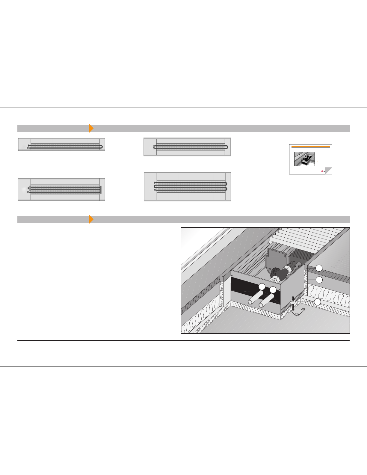
Einbausituation / Method of installation
4
1. Dauerelastische Randstreifen
2. Randschalldämmung
3. Trittschalldämmung
Bitte beachten Sie die Fensterseite!
Der Rohrleitungsanschluss erfolgt serienmäßig an der linken
Stirnseite, der Elektroanschluss befindet sich ebenfals links.
(Sonderanschlüsse sind auf Anfrage möglich.)
1. Continuously elastic border strips
2. Border acoustic insulation
3. Step-on acoustic insulation
Please observe the window side!
In series, the tube connection is performed on the left front side,
the electrical connection is also on the left side.
(Special connections are available on request.)
Lieferumfang / Scope of supply
Handbuch
User manual
V
R
1
2
3
Fensterseite
/ window side
Systemkonvektor WSK 320
System Convector WSK 320
Systemkonvektor WSK 260
System Convector WSK 260
Systemkonvektor WSK 180
System Convector WSK 180
Systemkonvektor WSK 410
System Convector WSK 410
WSK 180 / WSK 260 / WSK 320 / WSK 410
Einbauanleitung / Instructions of installations
Systemkonvektor
System Convector
WSK 180
WSK 260
WSK 320
WSK 410
HANDBUCH
USER MANUAL
WSK 260
5
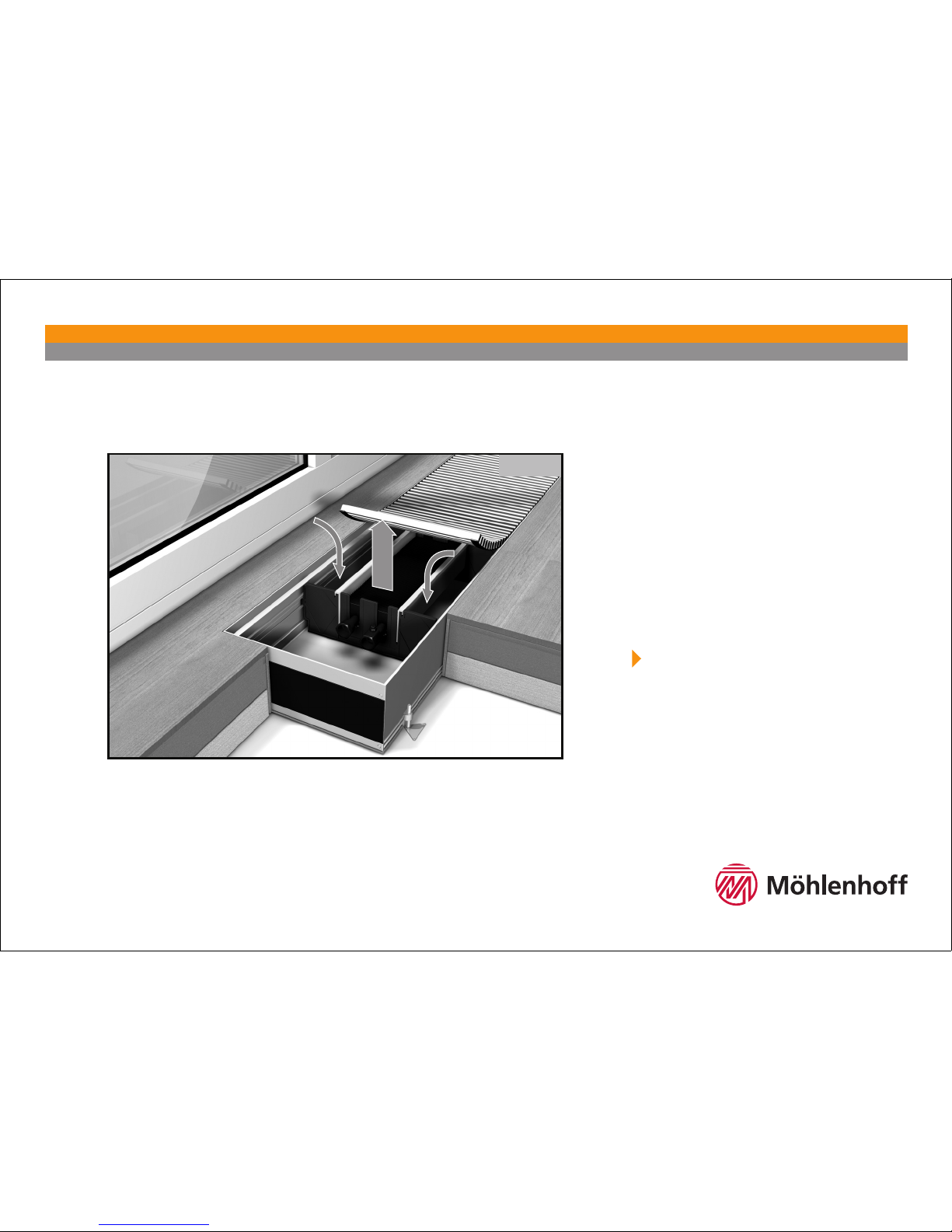
Montageabedeckung / Protective cover
Entfernen Sie die Montageabdeckung dauerhaft erst nach erfolgtem Einbau des Systemkonvektors
und dem Abschluss der Baumaßnahmen. Sie verhindern so die Verschmutzung bzw. die Beschädigung
des Systemkonvektors.
Die Rohrleitungsanschlussseite ist auf der Montageabdeckung mit einem "
"gekennzeichnet.
Remove the protective cover permanently only after finishing the installation of the System Convector
and after finishing all building work. By this you avoid contamination and damage to the System
Convector.
The tube connection side is marked with "
" on the protective cover.
WSK 180 / WSK 260 / WSK 320 / WSK 410
 Loading...