

MOFLASH SIGNALLING X201-18, X200-88, X201-19, X200-21, X200-22 Installation & Technical Manual
...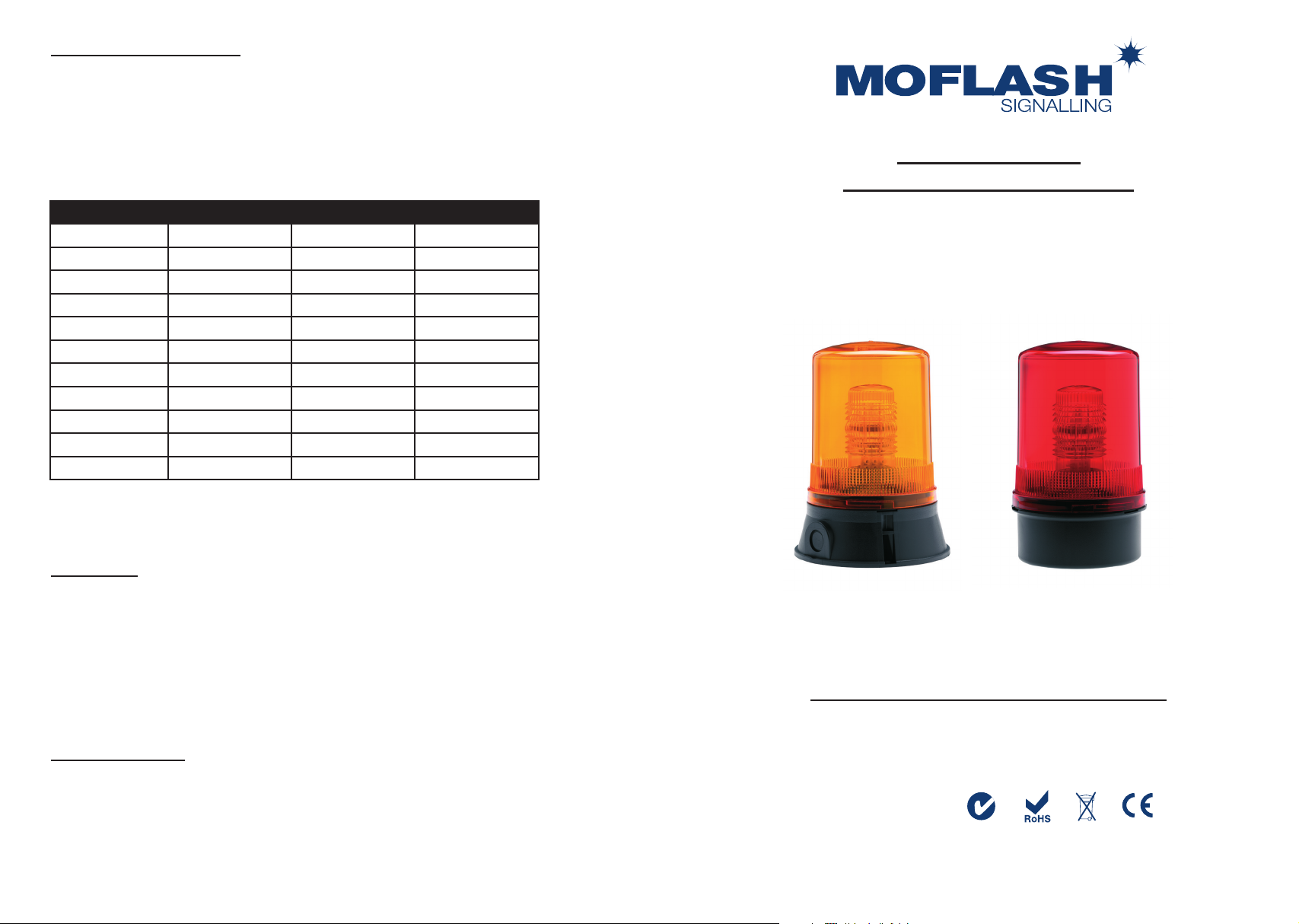
TECHNICAL DATA SHEET
This range of Xenon beacons are suitable for either internal or external use where a more
powerful warning signal is required. They produce 10 Joules of ash energy at 60 FPM
& when the double ash option is chosen the beacon produces 10 Joules rst ash and
7.5 Joules on the second ash. The light is emitted through 3600 around the vertical axis
and 1800 above the horizontal axis. The 201/200 series can be conduit box mounted.
All models can be surface or wall mounted (see accessories) as standard.
INSTALLATION &
TECHNICAL INFORMATION
Part Code: Voltage: Light Source: Current:
X201-18
X201-19
X200-88
X200-21
X200-22
X401-18
X401-19
X400-88
X400-89
X400-21
X400-22
Lens Colour Selection
01 = Amber, 02 = Red, 03 = Blue, 04 = Green, 05 = Clear.
Key Features
• Terminals except up to 1.5mm2 with wire protectors
• Ingress Protection: Weatherproof to IP65
• Case Material: UV Stable Polycarbonate Lens, UV Stable ABS Base
• Operating Temperature Range: -250c to +550c
• Continuously Rated
• AC Supply = 50/60 Hz
• Dual Voltage DC Option
• Multiple Flash Rate Available
12/24v Dc --- Xenon 10J / 7.5J 1.45 / 0.7 A
12/24v Dc --- Xenon 10J / 7.5J 1.45 / 0.7 A
24v Ac ~ Xenon 10J / 7.5J 0.72 A
115v Ac ~ Xenon 10J / 7.5J 0.10 A
230v Ac ~ Xenon 10J / 7.5J 0.06 A
12/24v Dc --- Xenon 10J / 7.5J 1.45 / 0.7 A
12/24v Dc --- Xenon 10J / 7.5J 1.45 / 0.7 A
24v Ac ~ Xenon 10J / 7.5J 0.72 A
48v Ac ~ Xenon 7J / 5J 0.37 A
115v Ac ~ Xenon 10J / 7.5J 0.10 A
230v Ac ~ Xenon 10J / 7.5J 0.06 A
PLEASE READ PRIOR TO INSTALLATION
X201/200 & X401/400 Series - (Xenon/Strobe)
VISUAL SIGNALLING DEVICES
Optional Equipment
• 50001 Mounting Bracket (X201/200 series only)
• 50004 Mounting Bracket (X401/400 series only)
• 50010 Cage Guard (cannot be used in conjunction with wall brackets)
• 50158 IP66 Weatherproof Band (X201/200 series only)
• 50080 Anti Vibration Mount (X201/200 series only)
Moash part code S00572
APPROVALS AND
CONFORMITIES
Website: www.moash.com Email: technical@moash.co.uk
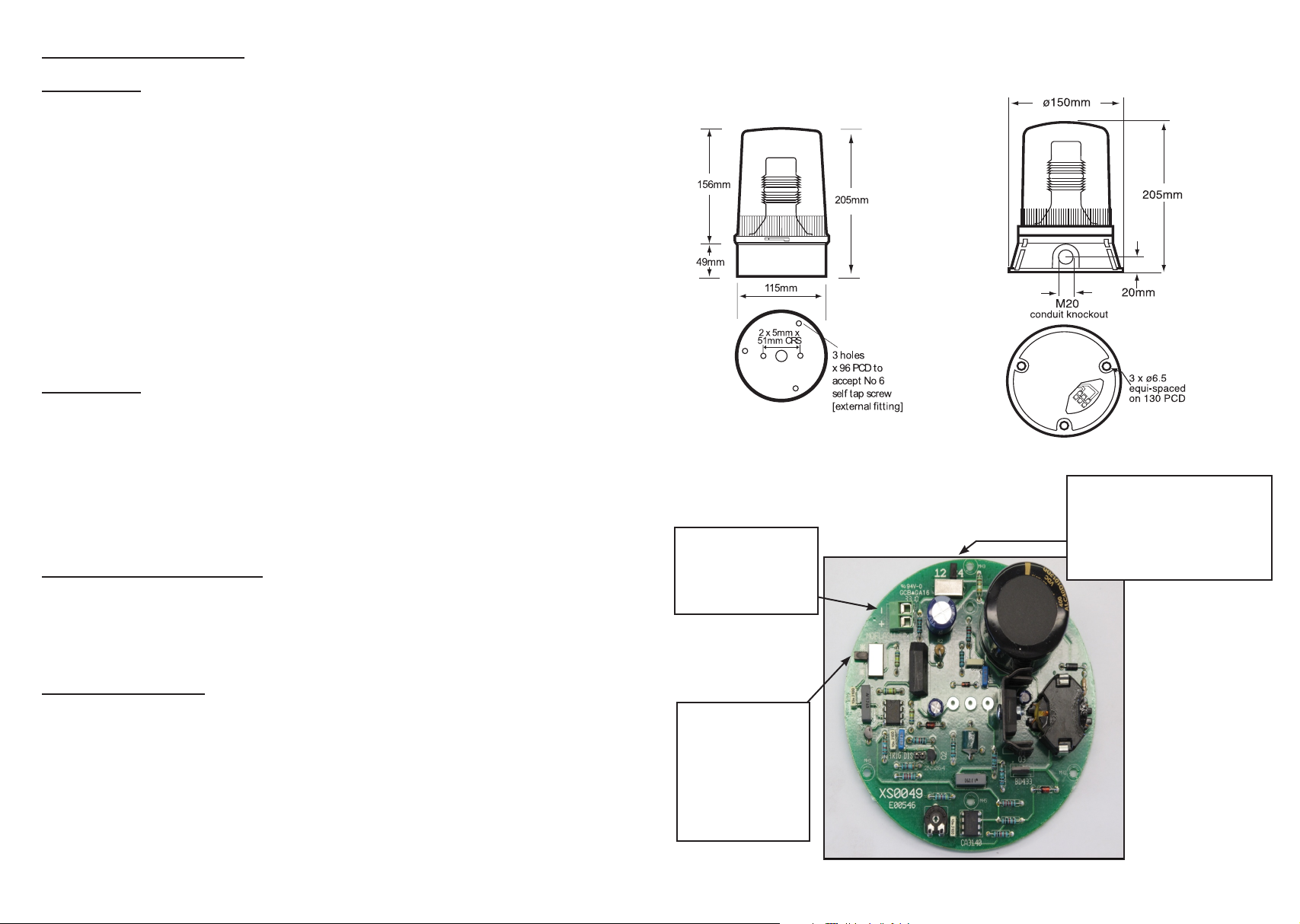
INSTALLATION DATA SHEET
X201/200 Series
Carefully twist lens rmly one turn clockwise to remove from base. Remove the inner PCB and
lens from the base of the unit. Fix base to the required surface, utilising rubber gasket, with 2 x M4
screws (not supplied). Insert power cable through aperture in base & connect to PCB.
For DC units connect to the two way terminal block marked ‘+’ for Positive & ‘-‘ for Negative. The
termination is polarity conscience see picture 1. Then select voltage required. The slide switch is
pre-set for 24v Dc. For 12v Dc move slide switch over to the 12 symbol. For AC units connect to
the two way terminal block marked ‘N’ for Neutral & ‘L’ for Live (not shown).
After power connection choose the alarm stage needed. See Modes of Operation below.
To re-assemble position the PCB assembly in the base noting the position of the three internal
mounting lugs. Fix the PCB onto the lugs using the 3 x No. 4 screws supplied. Replace lens onto
base ensuring that the base spigot ‘O’ ring is in place. Twist lens one turn anti-clockwise to lock
and check that the ‘O’ ring is positioned correctly and not caught or snagged.
X401/400 Series
Connection to this type of unit is either into the three way barrier strip situated in the base of the
unit (standard connection) or via the M20 side conduit entry. If M20 is preferred method then two
wires in the barrier strip in the base need to be unscrewed and freed from the barrier strip. Un-screw
3 x No. 4 screws that retain the base plate & carefully remove, threading the wires through the aperture.
Un-screw the same two wires from the internal terminal block. Carefully drill out the M20 entry &
using the appropriate cable gland, insert power cable into unit connecting to the internal terminal block.
Screw base plate back into position. Fix base to the required surface using the supplied gasket with
3 x M6 Hex set screws (not supplied).
Alarm Stages (Modes of Operation)
There is also an option to choose the units ash rate. The slide switch mounted on the PCB (see
picture 1) is pre-set to 60 FPM marked ‘*’ or for a 90 FPM rate move to position marked ‘**’. The
second ash generated with this mode of operation will be 25% less bright than the rst. There are
no other customer settings required.
X201/200 Series
POWER
CONNECTIONS.
DC VOLTAGE IN.
(AS MARKED)
Picture 1
X401/400 Series
PRE-SET AT 24V DC.
MOVE SWITCH TO
THE LEFT
POSITION FOR 12V DC
(AS MARKED)
General Installation Notes
• Installation must be carried out in accordance with the latest codes and regulations,
by a qualied electrician.
• Do not handle electronic components whilst wiring up, unless as indicated above.
• Ensure power is disconnected prior to installation or maintenance.
Xenon type units must be left for a minimum of 5 minutes after power
has been disconnected before maintenance can begin.
• Environmental exposure conditions during installation should be dry, not moist or wet.
• The lens of unit is Polycarbonate Plastic. Do not clean with petroleum based cleaners.
• To maintain the IP65 weatherproof rating, mount the beacon with the lens above the base.
• Avoid mounting beacon where it will be subject to excessive vibration.
PRE-SET AT
SINGLE FLASH.
SWITCH DOWN.
DOUBLE FLASH
AT TOP
(AS MARKED)
 Loading...