

MOFLASH SIGNALLING R201-13, R200-13, RA201-13, RA200-13, R401-13 Installation And Technical Information
...
TECHNICAL DATA SHEET
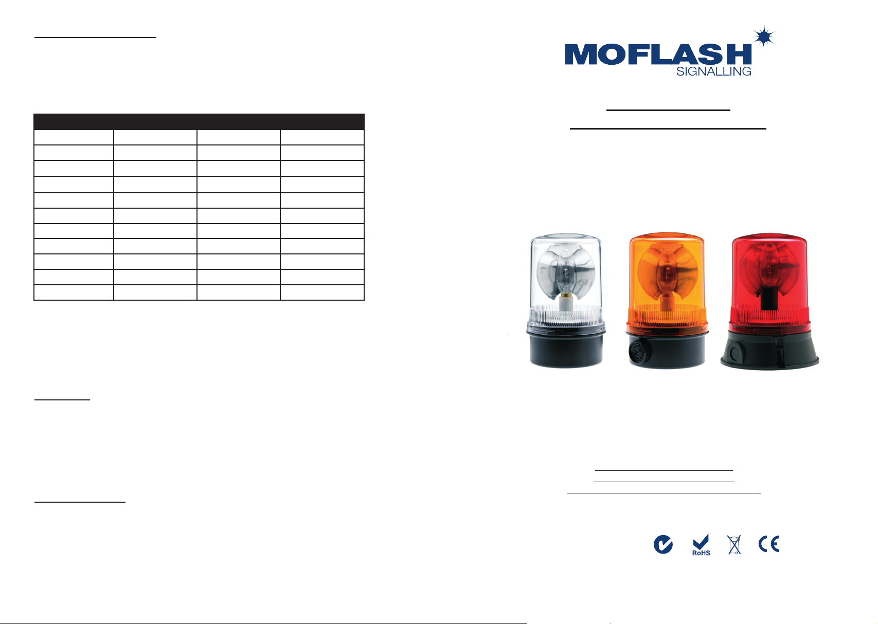
This range of traditional Rotating type beacons is a cost effective solution for signalling applications
where a powerful & commanding signal is required. It incorporates a parabolic reector which, once
energised, revolves around a continuously illuminated lamp. This creates a powerful beam of light
that sweeps through 3600. The units are driven by a twin belt drive system that is powered by a
synchronous wound motor for ‘AC’ units and a permanent magnet motor for ‘DC’ units. The RA series
also incorporates an audible alarm.
Part Code: Voltage: Light Source: Current:
#-13 12v Dc --- H1 x 55 W 4.70 A
#-14 24v Dc --- H1 x 70 W 3.00 A
#-29
#-61
l
l
24v Dc --- Ba15s x 10 W 0.60 A
24v Dc --- Ba15s x 21 W 0.95 A
#-63 24v Dc --- Ba15s x 48 W 2.00 A
#-02 48v Ac ~ Ba15d x 35 W 0.75 A
#-03 24v Ac ~ Ba15d x 48 W 2.00 A
R200-04 115v Ac ~ Ba15s x 60 W 0.55 A
R200-05 230v Ac ~ Ba15s x 60 W 0.29 A
R400-04 115v Ac ~ E14 x 60 W 0.55 A
R400-05 230v Ac ~ E14 x 60 W 0.29 A
# code = R201/R401 units
l
Diode Polarised for Fire Alarm Systems
Note: RA units have approximately a 25 mA higher current draw
INSTALLATION &
TECHNICAL INFORMATION
PLEASE READ PRIOR TO INSTALLATION
Lens Colour Selection
01 = Amber, 02 = Red, 03 = Blue, 04 = Green, 05 = Clear.
Key Features
• Terminals except up to 2.5mm2 cable
• Ingress Protection: Weatherproof to IP65
• Case Material: UV Stable Polycarbonate Lens, UV Stable ABS Base
• Operating Temperature: -100c to +550c
• Continuously Rated
• AC Supply: 50 Hz as standard
• RPM: DC operation = 160, AC operation = 120
Optional Equipment
50001 Mounting Bracket (R201/200 series only)
50004 Mounting Bracket (R401/400 series only)
50010 Cage Guard (cannot be used in conjunction with wall brackets)
50158 IP66 Weatherproof Band (R201/200 series only)
50080 Anti Vibration Mount (R201/200 series only)
Magnetic mount versions available (R201/200 series only)
Moash part code S00429
ROTATING MIRROR BEACONS
R201/200, RA201/200 & R401/400>
VISUAL & AUDIBLE SIGNALLING DEVICES
APPROVALS AND
CONFORMITIES
Website: www.moash.com Email: technical@moash.co.uk
INSTALLATION DATA SHEET
R201/200 and RA201/200 Series
Carefully twist lens rmly one turn clockwise to remove from base. Remove the inner reector
assembly from the base of the unit. Fix base to the required surface, utilising rubber gasket, with 2 x M4
screws (not supplied). Insert power cable through aperture in base & connect to terminal block on underside of
reector assembly.
For DC units connect Positive lead to the terminal block marked ‘+’ & Negative lead to terminal block marked
‘-’. The termination is polarity conscious. For AC units connect Live lead to terminal block marked ‘L’ &
Neutral lead to ‘N’. The termination is polarity conscious (see picture 1).
To Re-assemble, position the reector assembly in the base noting the position of the three internal mounting
lugs. Fix the assembly onto the lugs using the 3 x No.4 screws supplied. Replace lens onto base ensuring that
the base spigot ‘O’ ring is in place. Twist lens one turn anti-clockwise to lock and check that the ‘O’ ring is
positioned correctly and not caught or snagged.
R401/400 Series
Connection to this type of unit is either into the three way barrier strip situated in the base of the unit
(standard connection) or via the M20 side conduit entry. If M20 is the preferred method then the two
wires in the barrier strip in the base need to be unscrewed and freed from the barrier strip. Un-screw
3xNo.4 screws that retain the base plate & carefully remove, threading the wires through the
aperture. Un-screw the same two wires from the internal terminal block. Carefully drill out the M20 entry &
using the appropriate cable gland, insert power cable into unit connecting to the internal terminal block.
Screw base plate back into position. Fix base to the required surface using the supplied gasket with
3 x M6 Hex set screws (not supplied).
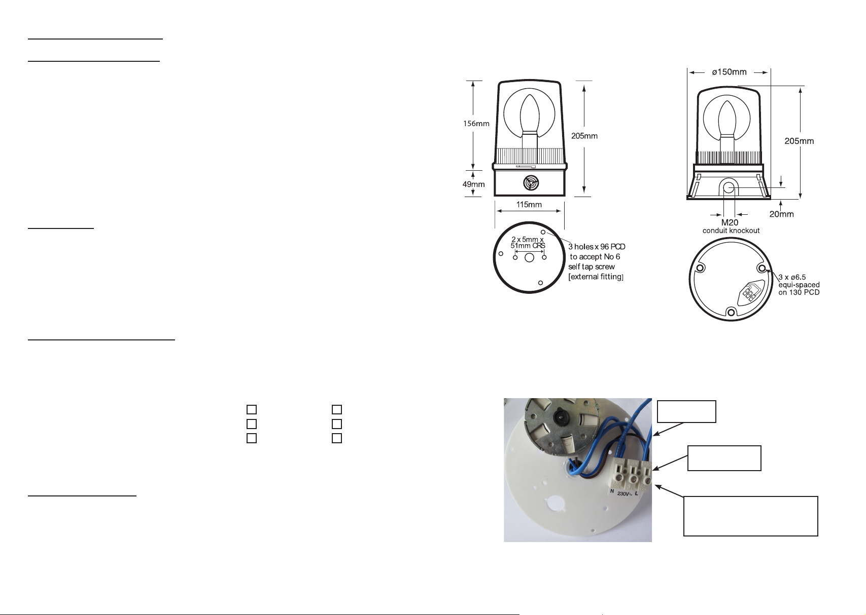
R201/200 and RA201/200 Series R401/400 Series
Alarm Stages (Modes of Operation)
The RA series is factory wired for combined operation of the audible and visual modes.
For 3 wire control giving independent operation of either lamp or buzzer the following adjustment is required.
Ensure the supply is disconnected before attempting adjustment.
Insert a 3mm at blade screwdriver into the inspection
slot of the terminal marked ‘+’ or ‘L’ (see picture 1) to
release the ‘wire grip’ and remove the Blue lead from
the back of the terminal top row. Be careful not to
dislodge the other Red/White/Blue leads, depending on
the model. Re-insert the Blue lead into the rear of the
unused middle terminal of the block (top row). Check security of all the leads. A third wire ‘+’ or ‘L’ can
now be connected to this terminal to allow independent use of lamp and buzzer.
RA201 RA200
‘+’ control of lamp
‘+’ control of buzzer
‘-’ common negative
‘L’ control of lamp
‘L’ control of buzzer
‘N’ common neutral
General Installation Notes
• Installation must be carried out in accordance with the latest codes and regulations by a qualied electrician.
• Ensure power is disconnected prior to installation or maintenance.
• Environmental exposure conditions during installation should be dry, not moist or wet.
• The lens of the unit is Polycarbonate Plastic. Do not clean with petroleum based cleaners.
• For all installations, mount the beacon with the lens above the base. Any other mounting position
will impair the IP rating (Ingress Protection) and shorten the working life of the beacon.
• Avoid mounting the beacon where it will be subject to excessive vibration.
Picture 1
LEAD TO
BUZZER
INSPECTION
SLOT
TERMINAL BLOCK
(RA200 CONNECTIONS
SHOWN. FACTORY SET)
 Loading...