

MOFLASH SIGNALLING X450, LED450, LED450-18, LED450-22, X450-18 Installation And Technical Information
...
7.0 Cable Gland
The X450 and LED450 beacons are supplied as standard with 1 x M20 threaded side cable entry with
provision for up to 4 supplied to special order.
SAFETY WARNING
If the X450 and LED450 are used at high ambient temperatures, ie over +400C then the cable entry
temperature may exceed +700C and therefore suitable heat resisting cable glands must be used, with a rated
service temperature of at least 950C.
INSTALLATION &
TECHNICAL INFORMATION
If a high IP (Ingress Protection) rating is required, a suitable sealing washer must be tted under the cable
gland. When only one cable entry is used, the other one must be closed with a blanking plug, which must
be suitably approved for the installation requirements.
8.0 End of Line Monitoring
An end of line monitoring diode or an end of line monitoring resistor can be connected across the 24v+ and
0 terminals. If an end of line monitoring resistor is required, this must be specied by the customer.
9.0 Maintenance
During the working life of the product, little or no maintenance is required due to the robust maintenance-free
surface. Composite material of PC (Polycarbonate) is abrasion and corrosion resistant therefore the
products are able to be used in both indoor and outdoor industrial conditions/under harsh environments.
It can also be applied in areas with high impact loads without additional protective constructions due
to very good mechanical properties.
If abnormal or unusual environmental conditions occur due to accident etc, visual inspection is
recommended. To avoid electrostatic charge build-up, only the exterior of the product can be cleaned
with a damp cloth. If spare parts are required, these can be supplied by Moash. If any failure occurs but
not caused by human factor, the product can be returned to Moash for free repair or replacement during
warranty period.
CAUTION:
Not suitable to be used under circumstance which exposed or near to the source or concentrated acids,
aromatic hydrocarbons, halogens and ketones.
10.0 Conditions for Safety Use
i) This apparatus is suitable to be used only in ambient temperature as stated below:
PLEASE READ PRIOR TO INSTALLATION
Type Ambient Temp
X450 and LED450 -400C to +700C
ii) Other than by the product manufacturer, painting and surface nishing are not permitted by the
third party.
iii) When used in dusty atmosphere, cable entry devices or stopping plugs have to be selected and installed
carefully in order to maintain the IP rating (IP66) of the product.
Moash part code S00583 - Issue 2
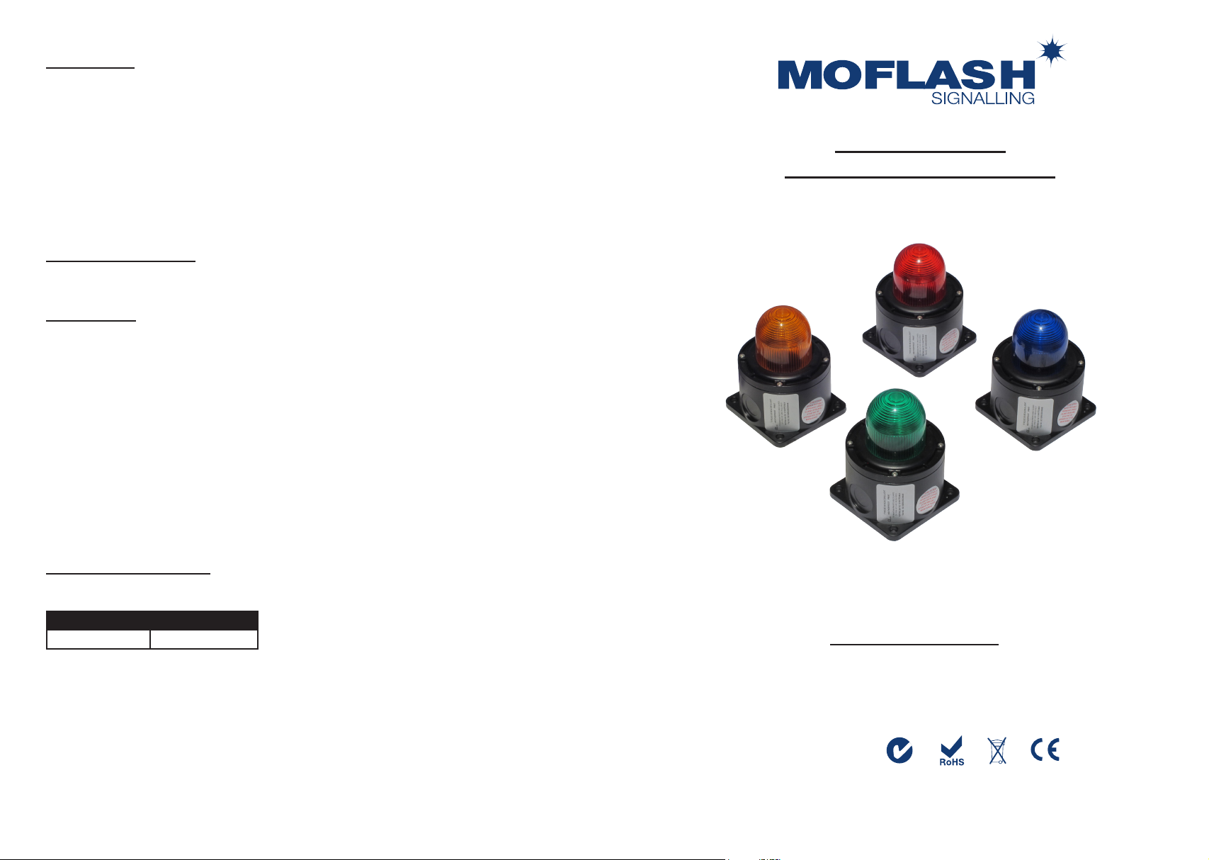
X450 & LED450 Series
Industrial Xenon & LED Beacons
VISUAL SIGNALLING DEVICES
APPROVALS AND
CONFORMITIES
Website: www.moash.com Email: technical@moash.co.uk
1.0 Introduction The LED450/X450 series are weatherproof beacons designed according to EN54 (BS 5839)
105.0
105.0
84.9
84.9
4-Ø5.6
FIX HOLE
END COVER
SCREWS
M4
105.0
105.0
84.9
84.9
4-Ø5.6
FIX HOLE
136.5
68.0
8.0
28.0
CABLE ENTRIES (x4)
TYPICAL PCB
L SO S2
N S1
DIP Switch
(2/3 pole)
(Xenon / LED)
1 2 3
ON
END COVER
SCREWS
M4
standard. The enclosure is a composite material of PC (Polycarbonate) and Fibreglass. The unique design
allows different Flash and Rotary rates, including Steady with the LED450 Beacon and Flash rates with the
X450 (Xenon) beacon.
Code Voltage Light Source Current
LED450-18 12-48v Dc --- 10 W 0.53 @ 24v
LED450-22 100-240v Ac ~ 10 W 0.08 @ 230v
X450-18 12-48v Dc --- 10 J 0.49 @ 24v
X450-22 100-240v Ac ~ 10 J 0.06 @ 230v
Removal of End Cover
Caution Ensure beacon is isolated from supply before removing cover.
Unscrew the four (4) M4 retained hex socket head screws. This will release the cover from the base and
allow the cover to hang on the retaining wire strap. Before replacing the cover, check that the joints are
clean and not damaged and that the gasket is still retained in the groove.
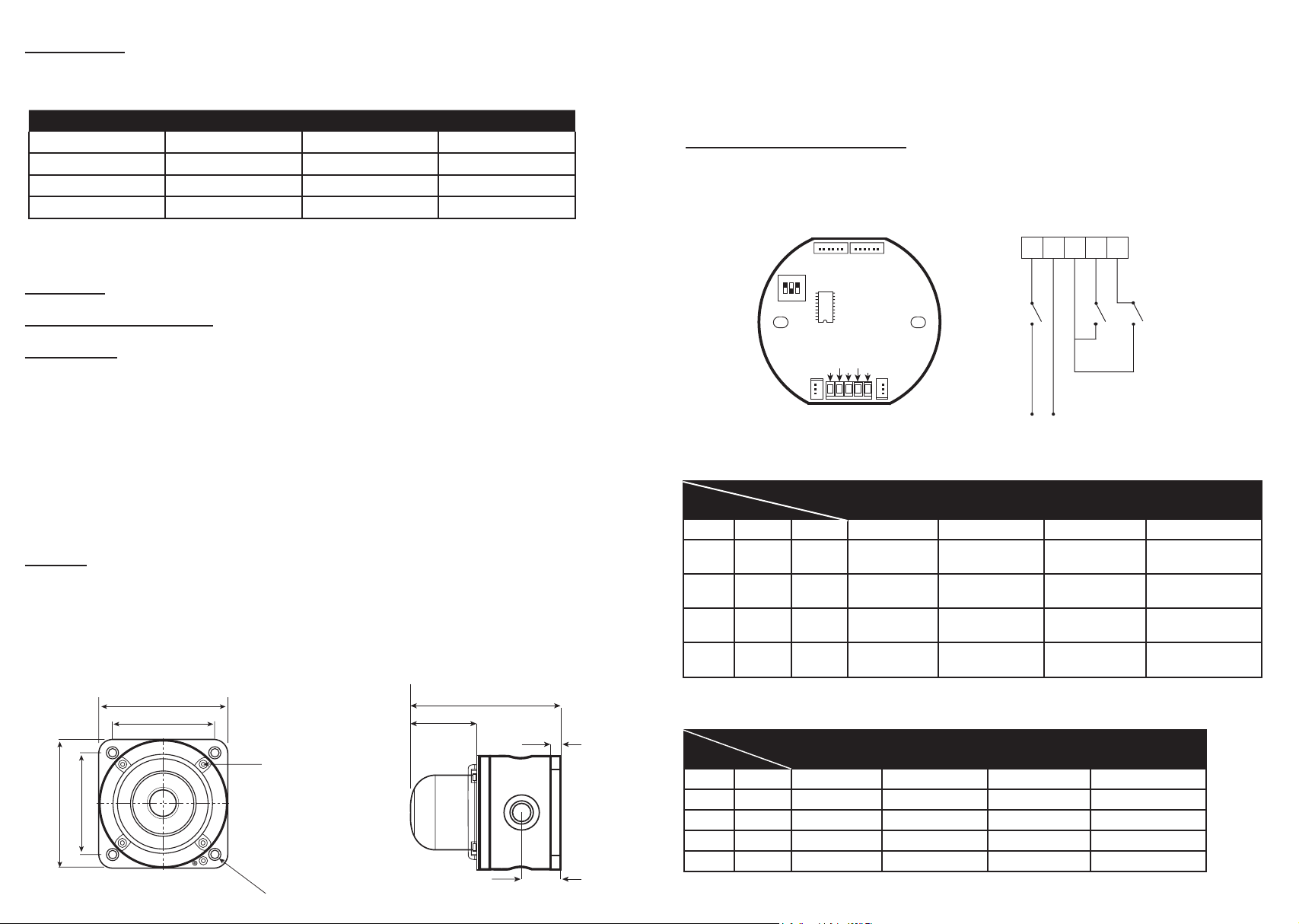
6.0 Status and Frequency Adjustment
DIP switches mounted on the PCB, 3 pole (LED450), 2 pole (X450) allow the frequency to be set
Binary code is 0=Off and 1=On. Alarm stages are managed via remote switching between S0 & S1 &
S2. Refer to Diagram 2 & Table 1 & Table 2. Dc units connect +v to terminal marked ‘L’ .
Do not connect Ac or Dc to terminals S0, S1 & S2.
Lens Colour Selection
01 = Amber, 02 = Red, 03 = Blue, 04 = Green, 05 = Clear.
2.0 Labelling Refer to label for Beacon Type, Voltage Type and Batch Code detail.
3.0 Temperature Classication Ambient temperature range -40
0
C to +70 0C
4.0 Installation
General Requirement
The product must be installed in accordance with the latest issued relevant requirements in the EN54 (BS 5839)
standard. Product installation must be carried out in accordance with any local codes that may apply and should
only be carried out by a competent electrical engineer.
Location The location of the unit should be made with due regard to the area over which the beacon warning
signal must be visible. The unit should only be xed to services that can carry the weight of the unit.
Mounting The products should be mounted on a vertical surface using four (4) xing holes in the
base. The xing holes are designed to t M5 Allen Screw only. Use of stainless steel fastener is recommended
by Moash. The beacon can be operated in any attitude. Refer to Diagram 1 for detail.
5.0 Wiring
General Requirement
Moash recommends that all cables and cores should be fully identied (suggest using cable from 1.5mm to
2.5mm2). Ensure that all nuts, bolts and screws are secured. Ensure that only the right and certied cable glands
are used and earthed correctly. Ensure correct cable glands and stopping plug are used to maintain IP rating.
Moash recommends SS316L for this application.
Cable Connection Should be carried out in accordance with relevant technical requirement.
Diagram 1
DIP Switch
(2/3 pole)
(Xenon / LED)
ON
1 2 3
L N S0 S1 S2
On O
Live (+)
N S1
L SO S2
Neutral (0)
Alarm stage selection
TYPICAL PCB
Diagram 2
LED/X450 BEACON
Table 1 - LED Beacon Frequency and Status Selection
S1/S2
DIP Switch
1st DIP 2nd DIP 3rd DIP Alarm Stage 1 Alarm Stage 2 Alarm Stage 3 Alarm Stage 4
0 0 0(1) OFF Flash
1 0 0(1) OFF Rotary
0 1 0(1) OFF Triple Flash
1 1 0(1) OFF Flash & Rotary
S1=OFF
S2=OFF
S1=ON
S2=OFF
60 (75) times/min
60 (75) times/min
60 (75) times/min
60 (75) times/min
S1=OFF
S2=ON
Flash
75 (90) times/min
Rotary
75 (90) times/min
Triple Flash
75 (90) times/min
Flash & Rotary
75 (90) times/min
S1=ON
S2=ON
Steady light
Steady light
Triple Flash
100 (120) times/min
Flash & Rotary
100 (120) times/min
Values in ( ) rate when 3rd DIP (1) On
Table 2 - Xenon Beacon Frequency and Status Selection
S1/S2
DIP Switch
1st DIP 2nd DIP Alarm Stage 1 Alarm Stage 2 Alarm Stage 3 Alarm Stage 4
0 0 OFF 60 times/min (1) 90 times/min (1) 120 times/min (1)
1 0 OFF 60 times/min (2) 60 times/min (3) 60 times/min (4)
0 1 OFF 60 times/min (3) 60 times/min (4) 60 times/min (5)
1 1 OFF 60 times/min (4) 60 times/min (5) 60 times/min (6)
S1=OFF
S2=OFF
S1=ON
S2=OFF
S1=OFF
S2=ON
S1=ON
S2=ON
All values in ( ) are the numbers of ashes per time
 Loading...