

Moflash X195-02WH-SB, X195-02WH, X195-05WH-SB, X195-05WH, X197-02WH Installation Instructions
Page 1
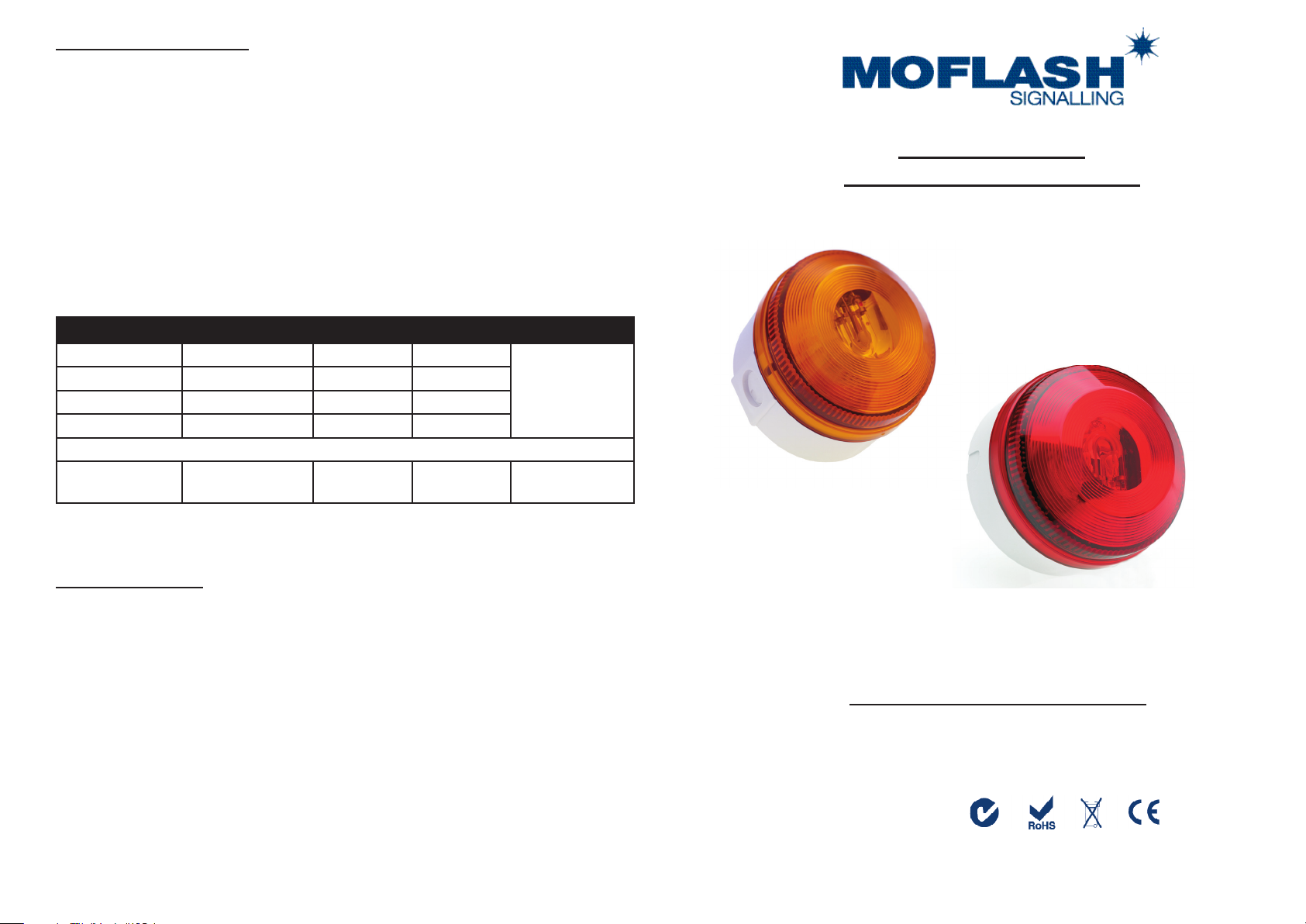
TECHNICAL DATA SHEET
The X195 and X197 are suitable for security, process control & general
industrial signalling applications.
These beacons are of the Flashing mode type (single stage alarm). Xenon beacons
(sometimes called strobes) are controlled via a PCB and put out a very brief but bright ash
of white light by ionizing and then discharging a large current through the xenon gas.
The design allows for termination inside the enclosure.
The X197 high power version only allows for internal connection via the M20 rear knockout.
The unit has provision for a Synchronous Mode of operation. This requires a third wire
connection & a remote synchronising module (not supplied).
Code No: Voltage: Light Source: Current:
X195-02WH-SB-
X195-02WH-
X195-05WH-SB-
X195-05WH-
X197-02WH 24v Dc --- Xenon 10.0 J 650mA ‘ON’ time of 2
For Lens colours add: 01 Amber, 02 Red, 03 Blue, 04 Green and 05 Clear
Key Features Include:
• Terminal block accepts up to 2.5mm cable incorporating rising
clamp protectors (1.5mm2 X197)
• Suitable for conduit box or wall mounting
• 1200 prime light output above the vertical axis
• Ingress Protection: Weatherproof to IP65
• Flash Rate: X195 - 60 Flashes / minute Nominal
• Flash Rate: X197 - 55 Flashes / minute Nominal
• Operating Temperature Range: -25 + 550c
• Enclosure Materials: UV Stable Polycarbonate Lens
UV Stable ABS Bases
• AC Supply: 50/60 Hz
Moash part code S00408 Issue 3
15-28v Ac/Dc ~ Xenon 5.0 J 310mA
15-28v Ac/Dc ~ Xenon 5.0 J 310mA
180-240v Ac ~ Xenon 5.0 J 110mA
180-240v Ac ~ Xenon 5.0 J 110mA
---
---
Rating:
Continuous
hours in any 6
INSTALLATION &
TECHNICAL INFORMATION
PLEASE READ PRIOR TO INSTALLATION
X195 & X197
Deep Base Option
X195 Shallow Base Option
X195 & X197 Series - (Xenon/Strobe)
VISUAL SIGNALLING DEVICES
APPROVED AND
CONFORMITIES
Website: www.moash.com Email: technical@moash.co.uk
Page 2
INSTALLATION DATA SHEET
Carefully pull the lens from the back box.
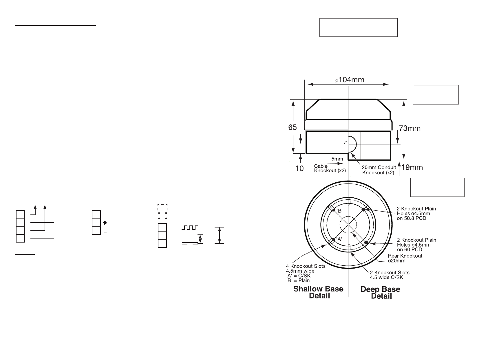
Remove the appropriate xing hole or conduit knockouts from the back box, noting:
X195 shallow base version: allows for 2 x 5mm side entry or 1 x M20 rear entry knockout.
X195 deep base version: allows for 2 x M20 side entry or 1 x M20 rear entry knockout.
X197 deep base version only: allows for 1 x rear entry supplied tted with weatherproof
grommet for cable 5-7mm diameter.
VISUAL SIGNALLING
DEVICE
Using the appropriate sealing gasket, t onto the required surface using 4mm fasteners
(Not supplied).
Pull sucient power cable/s into the back box enclosure and terminate cable/s into the Terminal
Block located on the PCB. (See diagram below).
X197 - Using the weatherproof sealing grommet supplied, insert the power cable/s and pull back
approximately 10mm of cable to form the correct seal.
Carefully replace the lens over the back box noting the following - X197 align lens PCB slots
over back box bosses. All units ensure ‘O’ ring is in position on base, power cables do not foul
PCB components and lens xing screws (where supplied) are aligned with base xing holes.
Screw in to secure lens.
X195 Ac/Dc (Low Voltage) X195 Ac (High Voltage) X197 Dc (Low Voltage)
Wiring Connections Wiring Connections Wiring Connections
LINK
I
I
+
+
24v Ac/Dc
Z
I
230v Ac ~
1 = 2 WIRE
2 = 3 WIRE
+24v
0v
+24v
2
WIRE3 WIRE
General
• Installation must be carried out in accordance with the latest codes of
practice and regulations by a qualied engineer.
• Ensure power source is disconnected prior to installation or maintenance to
avoid danger of electrical shock.
• Do not handle internal electrical components whilst wiring up.
• Environmental exposure conditions during installation should be dry. Moist or wet
conditions should be avoided.
• The lens material of the beacon is VO rated UV stable polycarbonate plastic.
Do not clean with petroleum based cleaners.
• Avoid mounting the beacon where it will be subjected to excessive vibration.
SIDE VIEW
OF BEACON
INTERNAL
VIEW OF BASE
 Loading...