

Page 1
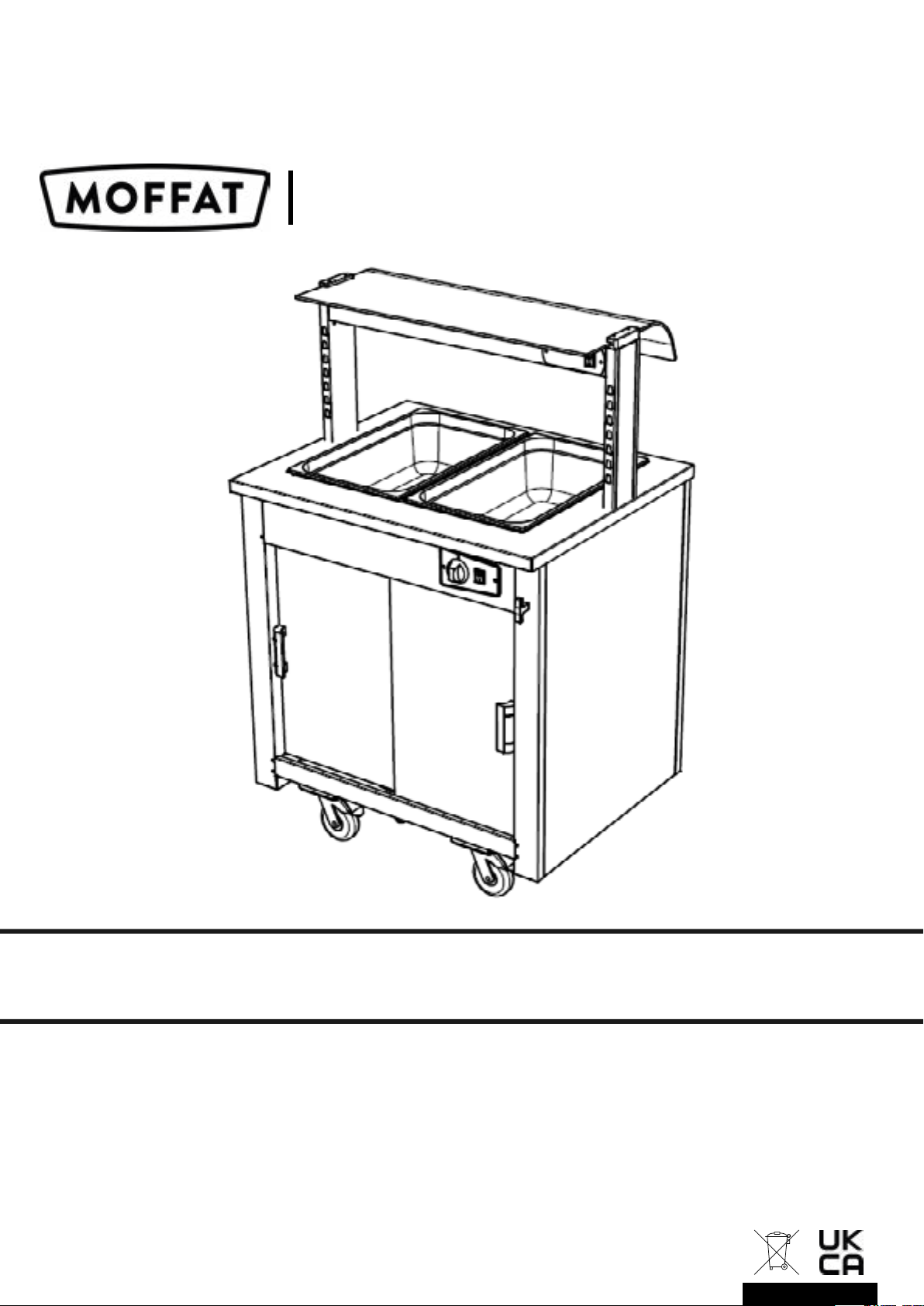
Versicarte-Pro
Operating & Service Manual
Manual 008 Issue 008 May 2025
Page 2
To ensure the best results from this unit please take the time to read and follow all
safety, installation and maintenance guidelines carefully before proceeding to install.
Keep this manual in a safe place for future consultation.
These appliances are marked in compliance with the relevant Low Voltage & EMC
Directives. Voltage stated on unit data plate.
Warning!
Please pay attention to sections of the manual displaying this symbol.
Do not attempt to use a hose or water jet to clean this unit.
For cleaning instructions, refer to section 15.
The appliance must only be used for the purpose it was designed for and may become
unsafe if used for any other purpose. Operators should be trained. The room where
this trolley is used must be dry, clean with temperatures between 16°C and 25°C and
with a maximum relative humidity of 60%. This unit is for indoor use only and has an
IPX4 rating.
Warning!
Depending on model, this unit’s system may be charged with a flammable refrigerant.
Important points that must be adhered to when using this product.
The position of the appliance must never be altered while connected to the mains
power supply.
The mains supply should never be turned o until the power has been turned o on
the appliance.
All brakes must be engaged while the appliance is being stored or is in use.
A mains power supply should be made available within 2.5m of where the appliance is
being used, never overstretch the power cable.
Multiple units must never be connected to a double 13amp socket.
only one appliance should be connected to a double 13amp outlet.
The Bain-marie openings must always be fitted with Gastronorm pans and lids.
both during heating up and during service, this is vital to maintain food temps
and energy eciency. Leaving the Bain-marie top open while switched on will
place unnecessary stress on the system and may result in integral part failures and
service issues.
Page 3
Contents
page
1
2
3
4
5
6
7
Electrical Specification
General Installation
Refrigerated installation conditions
Refrigerated Display and Refrigerated Well
Specification & Operation
Hot Cupboard
Specification & Operation
Hot Top
Specification & Operation
Bain-marie
Specification & Operation
4
5
6 /7
8 / 9
10 / 11 / 12
13
14 / 15
8
9
10
11
12
13
Heated Display
Specification & Operation
Soup Station
Specification & Operation
Carvery Station
Specification & Operation
Polar Well
Specification & Operation
Plate Dispenser
Specification & Operation
Crockery Dispenser
Specification & Operation
16 / 17
18
19 / 20 / 21
22
23 / 24 / 25/ 26
27
14
15
Changing Lights
Cleaning
28
29
Page 4
1: Electrical Specification
This appliance must be earthed and damaged cables must be replaced by a
suitably qualified person!
Live (L1)
L2
L3
Neutral
Earth
1 Phase Cable
Brown
X
X
Blue
Yellow & Green (Striped)
3 Phase Cable
Brown
Black
Grey
Blue
Yellow & Green (Striped)
A mains cable, type H07RN-F, conforming to code designation
60245 IEC 57, is supplied.
“If the supply cord is damaged, it must be replaced by the manufacturer, service agent or
suitably qualified person”
Appliance must be disconnected from the power supply during cleaning, maintenance and
part-replacement”.
Warning!
Check the 13amp
socket is in
good condition.
Do not use if the plug is
a slack fit and slides
into the socket easily.
Poor contact may
cause overheating
and failure over time.
Warning!
Do not overload socket.
Switch o before
inserting or removing
the plug.
E&R Moat Ltd.
will not accept any
responsibility
for issues caused by
faulty 13amp sockets.
Power Extensions and cables
Power extensions are not recommended, if an extension lead is used beware of the following.
• Never plug more than one appliance into a multi-way adapters / multi-way extension.
• Do not cross a pathway, leads being continually walked over will become damaged.
• Do not allow the cable to become over taut or over-stretched or continually bent.
• Do not allow cables to become tangled. Position carefully preventing risk of tripping.
• Only use an extension lead which was bought ready-assembled.
• Do not use an extension lead that is more than 15 metres long.
• Only use extension leads fitted with suitably insulated connectors and plugs.
• Always check the extension lead plug contains the correctly rated fuse.
• If using a cable drum extension, it should be completely unwound to avoid overheating.
Page 5
2: General Installation
Before installation please read the following points:
• When placing the counter bodies in position ensure there is adequate access.
• These mobile units can simply be butted up together to form a food service counter.
• Roll into position and apply the brakes on the operator’s side.
• Before installing, it is recommended that the floor is swept clean.
This equipment is designed to be operated by suitably qualified persons.
It is the responsibility of the Supervisor or equivalent to instruct users,
provide suitable P.P.E., show the mains isolating switch location, and
inform users that parts may become hot, causing injury if touched.
1. Remove all packaging & plastic coatings from the appliance.
2. Check for any damage.
When removing the stainless steel plastic protection film do not use sharp
implements. Extreme care must be taken to avoid scratching the stainless steel
surface underneath.
3. Assemble all parts, including shelves, food containers etc.
4. Hot cupboards: Ensure that the heater in the base is located correctly and plugged in.
5. Heated units: Fit the supplied halogen bulbs to the holders under the gantry.
6. Ensure all switches and thermostat controls are in the OFF position.
7. Connect the mains input plug to the socket outlet.
8. Turn on and check the unit is functioning correctly.
Page 6
3: Refrigeration installation conditions
Refrigerated Unit Venting
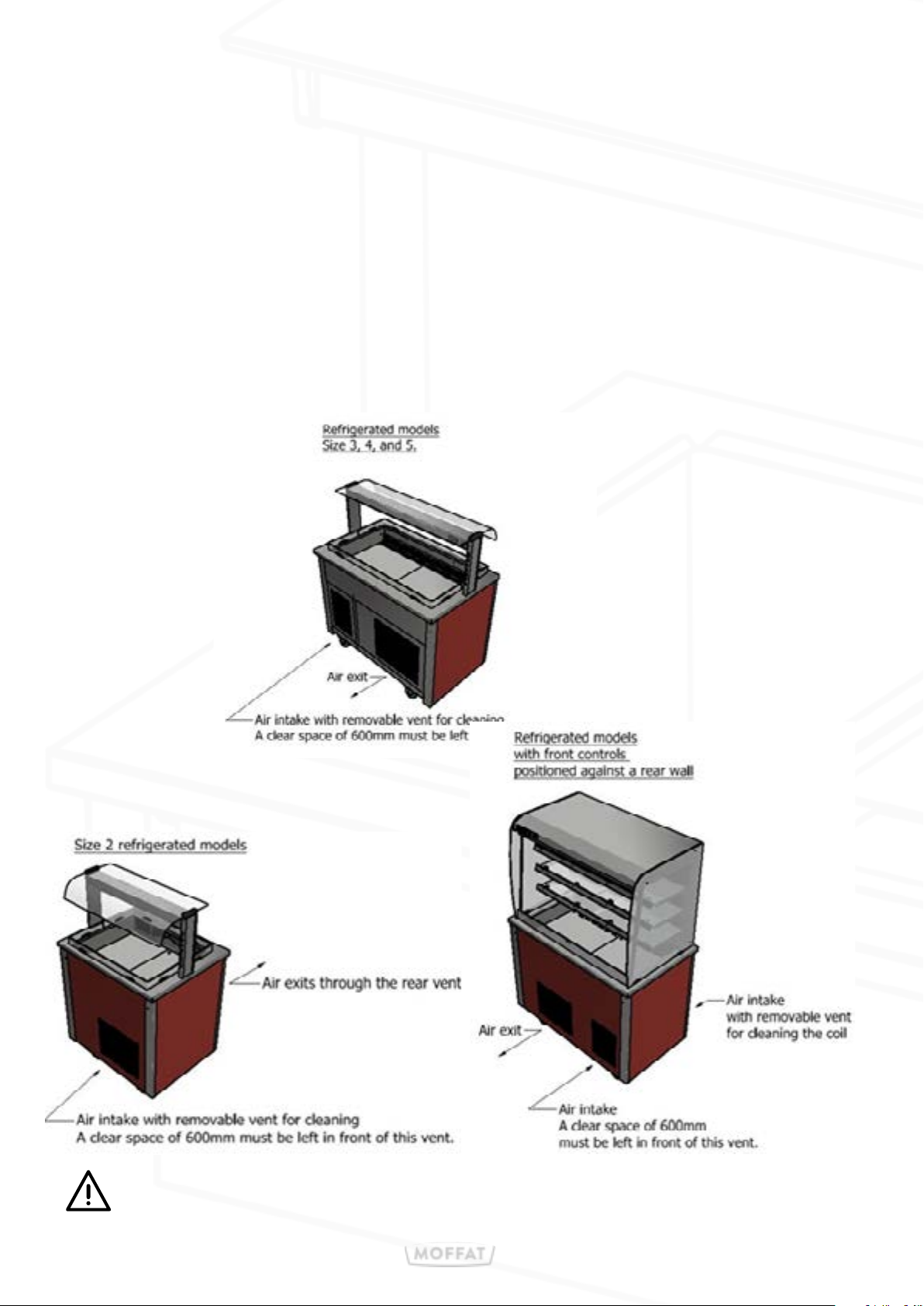
When installing these refrigerated units, allowances must be made for air venting.
It is crucial that there is an unrestricted air flow through the under slung compressor and condensing coil. Proper venting must be provided ensuring cool air from the room can be pumped in
through the condensing coil and out the other side.
The hot air blown out from the opposite side ‘must not’ be allowed to be sucked back through.
Blocked vents will cause reduced eciency and lead to malfunction
Page 7
3: Refrigeration installation conditions
To ensure the satisfactory operation and optimum eciency of this
unit, it is imperative that the ambient room conditions where the units
are being used do not exceed a room temperature of 25°c or exceed
a relative room humidity of 60%.
Should conditions exceed the above, the display units may not maintain food temperatures at the
required levels.
E & R Moat cannot accept responsibility for the performance of the units being used in extreme
conditions.
Do not install units where there is high radiated heat,e.g. direct sunlight, room
heaters, or bright spot lights. Do not install units in draughty
conditions where the air movement is greater than 0.2mtr/sec.
(e.g. near doors, windows, air conditioning units or fans]
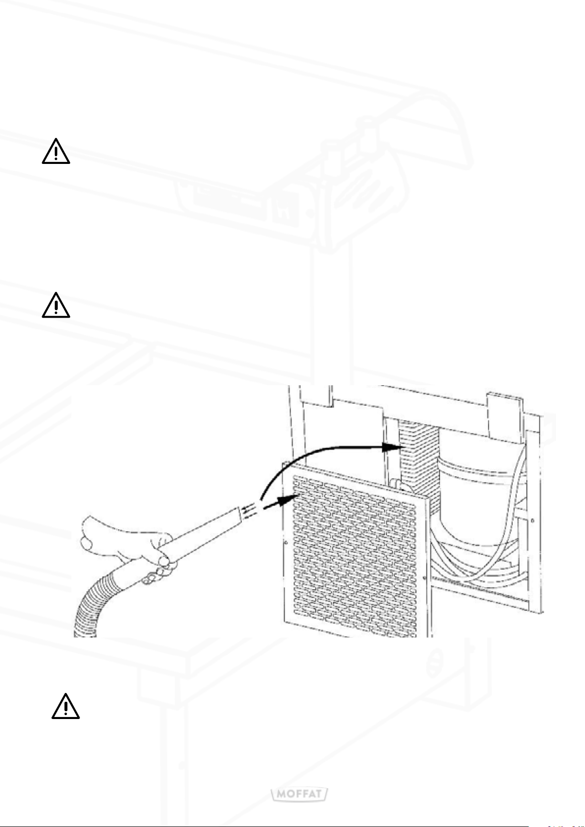
The condensing coil & vents requires
regular cleaning to maintain the
performance of the unit, as air borne
particles will choke the coils fins. They
should be cleaned with a soft brush and
vacuum.
These units require good airflow inside and outside. It is essential the vents
in the external panels do not become blocked as this can cause the unit to
fail, due to overheating. Internally good air flow must also be maintained, a
small space should be left between all products.
Page 8
4: Refrigeration well specification
Model
VC2RW
VC3RW
VC4RW
VC5RW
Weight
(kg)
95
125
155
185
Dimensions
L X W X H (mm)
830 x 680 x 900
1158 x 680 x 900
1486 x 680 x 900
1814 x 680 x 900
Electrical
Supply
13amp
13amp
13amp
13amp
Power Rating
(kw)
1.2
1.2
1.2
1.5
4: Refrigeration display specification
Model
VC2RD, VC2RDF,
VC2RDFC, VC2RDSL,
VC2RDSLF.
VC3RD, VC3RDF, VC3RDFC,
VC3RDSL, VC3RDSLF,
VC3RDSLFC.
Weight
(kg)
110
150
Dimensions
L X W X H (mm)
830 x 680 x 1650
1158 x 680 x 1650
Electrical
Supply
Power Rating
with a gantry
1.22
1.23
1.23
1.53
Power Rating
13amp
13amp
(kw)
1.5
1.7
VC4RD, VC4RDF, VC4RDFC,
VC4RDSL, VC4RDSLF,
VC4RDSLFC
VC5RD, VC5RDF, VC5RDFC,
VC5RDSL, VC5RDSLF,
VC5RDSLFC
VC2RDSA, VC2RDSAFC
VC3RDSA, VC3RDSAFC
VC4RDSA VC4RDSAFC
VC5RDSA VC5RDSAFC
This unit’s system is charged with a flammable refrigerant (R290).
Before commencing there are certain environmental parameters that must
190
230
120
165
210
255
1486 x 680 x 1650
1814 x 680 x 1650
830 x 680 x 1700
1158 x 680 x 1700
1486 x 680 x 1700
1814 x 680 x 1700
13amp
13amp
13amp
13amp
13amp
13amp
1.7
1.7
1.5
1.7
1.7
1.7
be followed please read the additional installation conditions on page 6 & 7.
Page 9
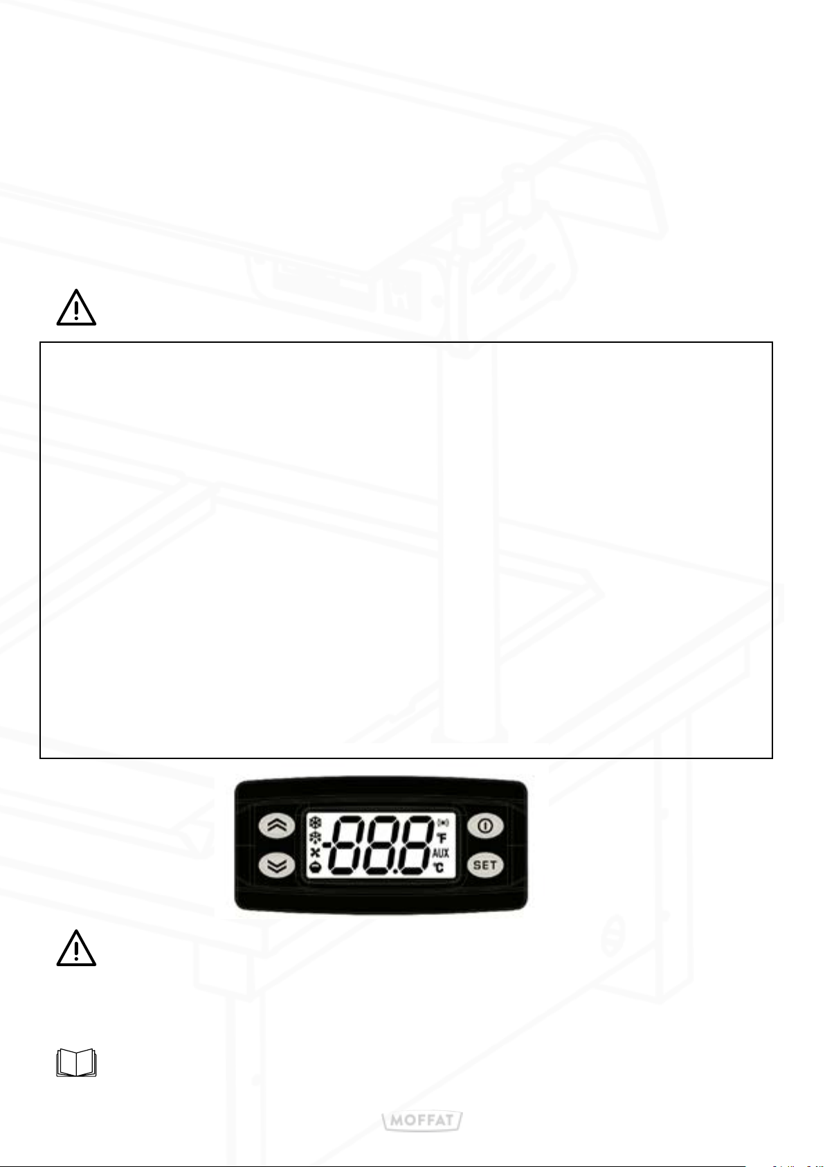
Refrigerated Units
4: Refrigeration model operation
Refrigerated display units are designed to keep pre-chilled food at a regulated
serving temperature and are suitable for the display of most types of cold food.
Designed to provide a gentle flow of cold air maintaining a safe and compliant
temperature within. The Chilled display has an automatic defrost, and automatic
condensate water evaporation system, eliminating the need to manually empty drip
trays or on-site drainage.
The Display unit is controlled by a green neon on/o switch and a digital control.
• Connect plug to 13-Amp socket and switch on at mains socket.
• Power on with green illuminated Switch
• Digital illuminates and controls the display temperature
• Allow 30mins for the display too cool down before loading product
• The controlled air temperature is factory set to operate between 2° and 5°
• Defrost is factory set to operate automatically when required
The controlled air temperature is factory set to operate between 2° and 5°.
• When serving is complete all switches should be turned o.
To enable automatic defrost, the13A plug must be constantly switched
on. The green switch can be switched o when the cooling is no longer
required, however, do not un-plug the unit from the mains power.
Product should already be 5° or below before loaded into the display
These units are not designed to chill down hot food
Page 10
5: Hot cupboard
Model
VC2HC
VC3HC
VC4HC
VC5HC
Weight
(kg)
34
51
68
85
Dimensions
L X W X H (mm)
830 x 680 x 900
1158 x 680 x 900
1486 x 680 x 900
1814 x 680 x 900
Electrical
Supply
13amp
13amp
13amp
13amp
Power Rating
(kw)
0.9
1.5
1.5
1.9
Hot storage cupboards are designed for preheating Plates & Dishes, as well as the
temporary storage of precooked food whilst service is in progress e.g.
Cooked meats, poultry, vegetables, sauces, etc. They are heated via a removable
‘Sahara’ fan heating cell. Fitted with removable sliding doors and removable
adjustable for height rod shelves, which are split into manageable sections to ease
cleaning and maintenance.
Refer to page 11, for details on how to remove Sahara fan heating cell.
for door and shelving adjustment and removal see page 12
The correct Holding temperature is dependent on the food type, amount of food in
container, etc. always keep doors closed whenever possible
These units are not designed to heat up cold food.
The Hot cupboard is controlled by green neon on/o switch and a 30° to 110°
thermostat control knob.
• Connect plug to 13-Amp socket and switch on at mains socket.
• Power on with green illuminated Switch and turn Control Knob to position 110
• Leave for 15mins to reach serving temperature
• Set the temperature of the Hot cupboard to the desired position
• Dishes can now be loaded.
• When serving is complete all switches should be turned o.
• To maintain the life clean regularly with a damp cloth.
These units will remain hot for a long period of time after use
Page 11
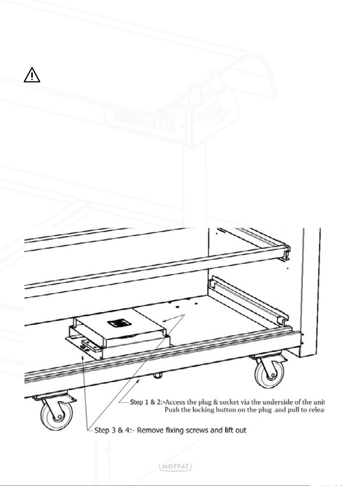
5: Hot-cupboard
Sahara fan removal & installation
Isolate appliance from power supply & allow to cool down before removal.
The unit can be easily removed & replaced for cleaning or maintenance, due to a
simple IEC type fastening system.
• Access to the Plug & socket is via the underside of the unit
• Locate the locking button on the plug and cable push in a pull to release
• Inside the cupboard remove the rod shelf sections to allow access.
• Remove fixing screws and lift out at a slight angle
• Fitting is a reversal of the above.,
Page 12
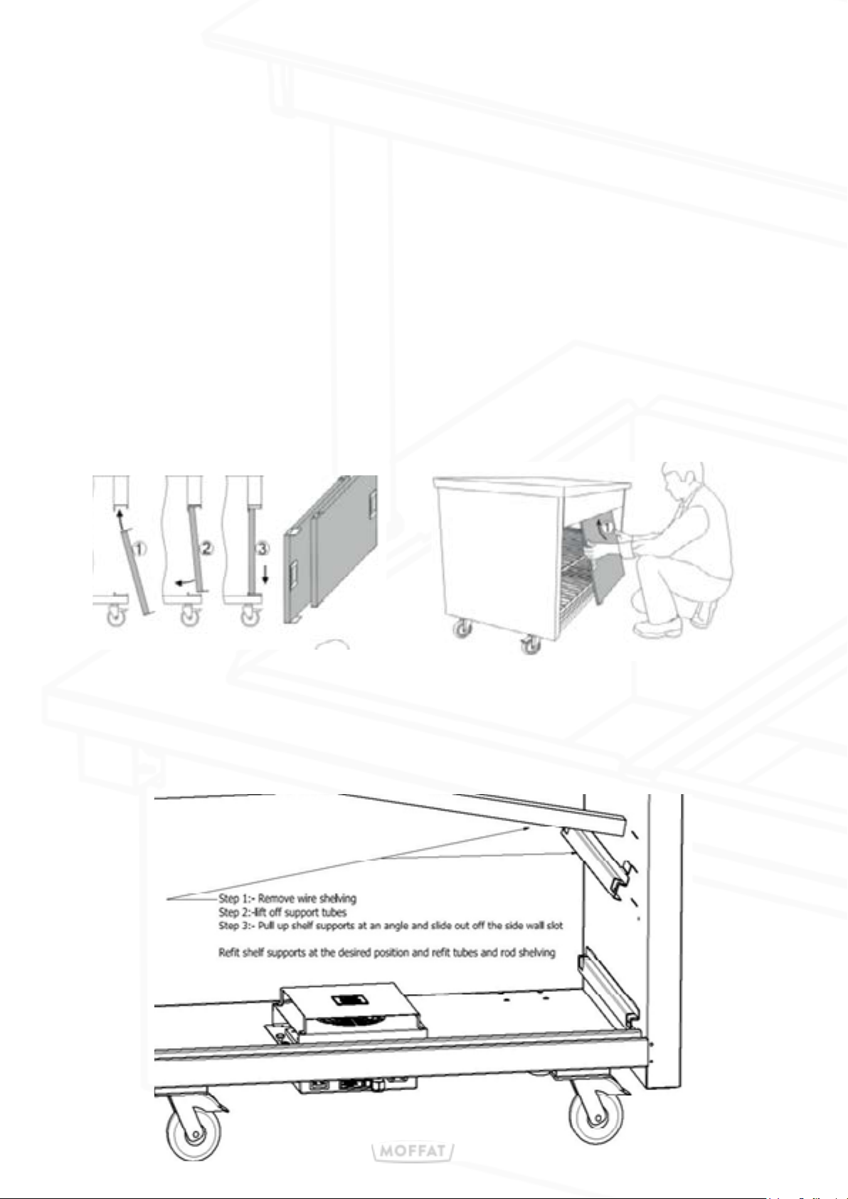
5: Hot-cupboard
Hot Cupboard Doors
Fig 1 demonstrates the fitting of the cupboard doors;
in this case, the rear door (Door A).
1. Hold the door at a slight angle & locate the door fully into the top track.
2. Swing the bottom of the door inwards connecting with the bottom track
3. Lower the door into the bottom track, & slide the door fully to the left.
The fitments of the outer door (Door B) is the same as above, except when lowered
into the bottom track slide it fully to the right.
Note: It’s imperative the doors must be fitted in correct order
as shown below - Door ‘A’ first then Door ‘B’
Door removal is a reverse of the above.
Hot Cupboard shelf removal adjustment
Rod shelving lifts o in easy sections. Shelf support tubes can also be lifted out of
the
supports and removed.
The side supports can be removed or adjusted for three height positions.
Page 13
6: Hot Top with hot-cupboard
Model
VC2HT
VC3HT
VC4HT
VC5HT
Model
VC2HCS
VC3HCS
VC4HCS
VC5HCS
Weight
(kg)
55
82
110
137
Weight
(kg)
45
67
90
112
Dimensions
L X W X H (mm)
830 x 680 x 900
1158 x 680 x 900
1486 x 680 x 900
1814 x 680 x 900
Dimensions
L X W X H (mm)
830 x 680 x 900
1158 x 680 x 900
1486 x 680 x 900
1814 x 680 x 900
Hot plates
(kw)
2 x 0.18
3 x 0.18
4 x 0.18
5 x 0.18
Top
(kw)
0.75
1.0
1.0
1.1
Fan
(kw)
0.9
1.5
1.5
0.9
Fan
(kw)
0.9
0.9
0.9
0.9
Electrical
Supply
13amp
13amp
13amp
13amp
Electrical
Supply
13amp
13amp
13amp
13amp
Rating
(kw)
1.26
2.04
2.22
1.80
Rating
(kw)
1.65
1.90
1.90
1.90
With Gantry
(kw)
1.48
2.48
2.88
2.68
With Gantry
(kw)
1.87
2.34
2.56
2.88
Hot Tops are designed to keep pre-cooked food at serving temperature and are suitable for the display of most types of hot foods. They are fitted with either easy to
clean Neo-Ceram thermo panels or a solid stainless steel top with a solid state ele-
ment under The self-regulated surface temperature is controlled at around 90°.
These units are not designed to heat up cold food.
The correct serving temperature is dependent on the food type, and quantity
Flat bases dishes are recommended to allow best heat transfer.
The Hot Top & Gantry are both controlled by green neon on/o switches
hot cupboard controlled by a 30° to 110° thermostat control knob.
• Connect plug to 13-Amp socket and switch on at mains socket.
• Power on with green illuminated Switch
• Turn Control Knob to position 110
• Leave for 15mins to reach serving temperature
• Set the temperature of the Hot cupboard to the desired position
• Dishes with ‘precooked’ food can now be loaded.
• When serving is complete all switches should be turned o.
• To maintain the life clean regularly with a damp cloth.
These units will remain hot for a long period of time after use
Page 14
7: Bain marie ( Dry heat) with hot-cupboard
Model
VC2BM
VC3BM
VC4BM
VC5BM
Weight
(kg)
45
67
90
112
Dimensions
L X W X H (mm)
830 x 680 x 900
1158 x 680 x 900
1486 x 680 x 900
1814 x 680 x 900
Bainmarie
(kw)
0.75
1.0
1.0
1.1
Fan
(kw)
0.9
0.9
0.9
0.9
Electrical
Supply
13amp
13amp
13amp
13amp
Rating
(kw)
1.65
1.90
1.90
2.00
With Gantry
(kw)
1.87
2.34
2.56
2.88
Bain-marie units are designed to keep pre-cooked food at serving temperature and are suitable
for the display of most types of hot foods, complete with an inset well designed to accommodate
various combinations of interchangeable Gastronome type pans up to 150 mm deep. Each
opening can also be fitted with an optional spiked carvery pad or Neo-Ceram Hot Top adaptor.
These units are not designed to heat up cold food.
The correct serving temperature is dependent on the food type, amount of food in container,
etc. Fit empty pans and lids into their openings before switching the unit on. After the 30mins
has elapsed load food and replace lids. Do not remove lids until service is due to commence.
The Bain-marie & Gantry are both controlled by a green
neon on/o switch and a digital
temperature control.
• Connect plug to 13-Amp socket and switch on at mains socket
• Power on with green illuminated Switch
• Turn Control Knob to position 110
• Leave for 30mins to reach serving temperature
• Set the temperature of the Bain-marie to the desired position
• Precooked food can now be loaded.
• When serving is complete all switches should be turned o.
• To maintain the life clean regularly with a damp cloth.
These units will remain hot for a long period of time after use
Page 15
7: Bain marie (Wet / Dry heat) & hot-cupboard
Model
VC2BM
VC3BM
VC4BM
VC5BM
Weight
(kg)
51
75
101
125
Dimensions
L X W X H (mm)
830 x 680 x 900
1158 x 680 x 900
1486 x 680 x 900
1814 x 680 x 900
Bainmarie
(kw)
2 x 0.75
2 x 1.0
2 x 1.0
2 x 1.0
Fan
(kw)
0.9
0.9
0.9
0.9
Electrical
Supply
13amp
13amp
13amp
13amp
Rating
(kw)
2.40
2.90
2.90
2.90
With Gantry
(kw)
2.62
3.34
3.56
3.78
This Bain-Marie well can be used either dry or wet heat with an inset well designed to
accomodate various combinations of interchangable gastronome type pans up to 150mm deep.
Bain-marie units are designed to keep pre-cooked food at serving temperature and are suitable
for the display of most types of hot foods.
Wet Heat:
Water level is an economic, 20mm deep [water level mark on side of well], complete
with drain valve and swing-out, run-o tube for easy emptying.
1. First check the drain valve inside the left-hand door of the hot-cupboard
is in the closed position.
2. Remove the Bain-Marie container situated at one end. Check the water level
mark on the side of the well. (approximately 20mm deep max)
3. Carefully fill well with water up to the water level mark
If required top up water level mid service, use suitable heat resistant gloves when
removing the hot bainmarie container.
Do not over fill with water. too much water will impinge on performance and
eciency
4. Replace the container and switch on and Turn Control Knob to position 3 (full on)
5. Turn hot-cupboard control to 110°C.
6. Leave to heat up for approximately 45 minutes before filling containers with food.
7. After 45min set the temperature of the Bain-marie to the desired position
8. Precooked food can now be loaded.
Dry Heat:
Dry heat works in the same way without any water in the well. Heat up time will be around 30 min
The base of the well will distort slightly and discolour when used dry. This is normal.
These units will remain hot for a long period of time after use
Page 16
8: Heated display with storage cupboard
Model
VC2HD & VC2HDF
VC3HD & VC3HDF
VC2HDSL & VC2HDSLF
VC3HDL & VC3HDSLF
Weight
(kg)
90
125
96
132
Dimensions
L X W X H (mm)
830 x 680 x 1650
1158 x 680 x 1650
830 x 680 x 1655
1158 x 680 x 1655
Electrical
Supply
13amp
13amp
13amp
13amp
Designed to keep pre-cooked food at serving temperature and are suitable for the
display of most types of hot foods. . Complete with either sliding
glass rear doors.
Power Rating
(kw)
1.05
1.50
1.05
1.50
These units are not designed to heat up cold food.
The correct serving temperature is dependent on the food type, quantity and packaging, etc.
The Display unit is controlled by a green neon on/o switch and a digital
temperature control.
• Connect plug to 13-Amp socket and switch on at mains socket.
• Power on with green illuminated Switch
• Digital illuminates and controls the display temperature
• Leave for 30mins to reach serving temperature
• Set the temperature of the display to the desired position
(Factory set at 80° adjustable between 60° and 95°]
• Precooked food can now be loaded.
• When serving is complete all switches should be turned o.
• To maintain the life clean regularly with a damp cloth.
These units will remain hot for a long period of time after use
Page 17
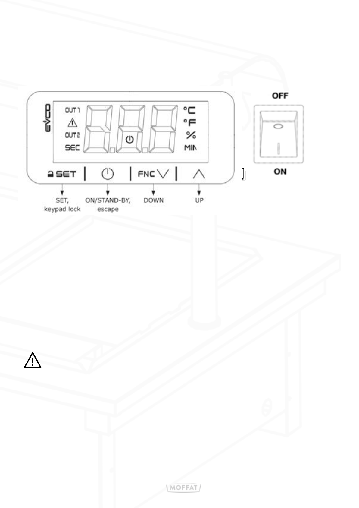
8: Heated display with storage cupboard
How to Change the Temperature Setting
Unlocking the keypad
• Press any button (SET, ON/STAND-BY, DOWN or UP) the display shows LoC
• Press and hold the SET, keypad lock button for 1 second and the display will show UnL.
Setting the temperature setpoint
• Touch the SET button and use either the DOWN or UP buttons to change the set point.
• Once the set point has been chosen, press the SET button to confirm,
or press the ON / STAND-BY, escape button to cancel.
Note
If the SET or ON / STAND-BY, escape buttons are not pressed within 15 seconds of making a
change the action will be cancelled.
• Hot display units, bain-maries, and hot tops, are designed to hold pre-heated food
products at regulated temperatures in an ambient room temperature above 16°C.
• Consideration should be made when sighting to avoid positioning
close to air conditioning vents, windows and doors where cold
draughts may be present.
(Food temperature and quality may be aected).
• Do not install units in draughty conditions where the air movement is greater than
0.2mtr/sec
Page 18
9: Soup station
Model
VC2SS
Weight
(kg)
45
Dimensions
L X W X H (mm)
830 x 680 x 970
Electrical
Supply
13amp
Power Rating
(kw)
0.70
These soup kettles are designed to hold ‘pre-cooked’ soups and gravy at serving
temperature
Along with a removable drip tray which aids cleaning, they also come supplied with
two 4,5litre stainless steel pots, complete with stainless steel lids.
The correct serving temperature is dependent on the food type / amount etc.
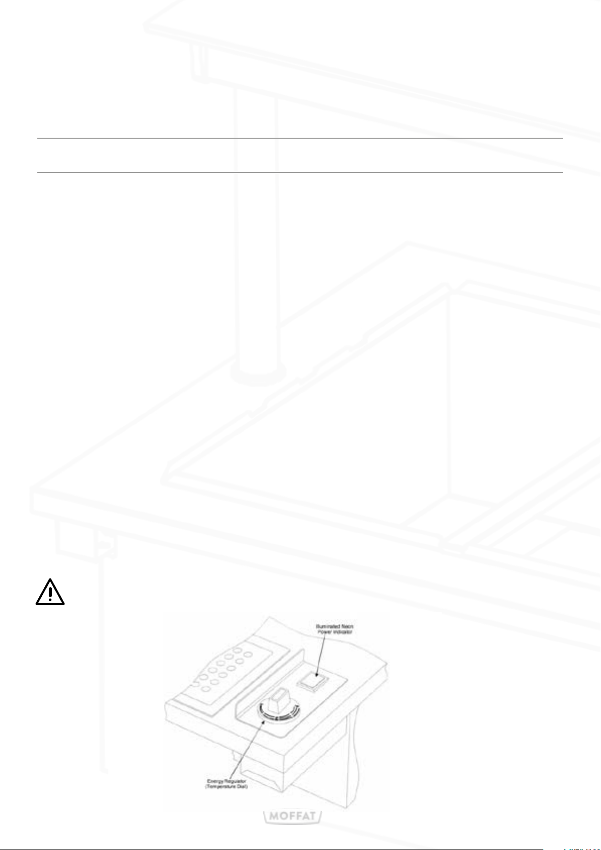
Controls are surface mounted for convenience and consist of a neon power indicator and an energy regulator dial.
• Connect plug to 13-Amp socket and switch on at mains socket.
• Fit empty pans and lids into their openings
• Power on with green illuminated Switch
• Turn control Knob to position No 3
• Leave for 30mins to reach serving temperature
• Set the Knob to the desired position (Position No 3 is full power, Position)
• Precooked Soup can now be loaded.
• Do not remove lids until service is due to commence.
• When serving is complete all switches should be turned o.
• To maintain the life clean regularly with a damp cloth.
These units are not designed to heat up cold food.
Page 19
10: Carvery station
Model
VC4CS, VC4CSSL
Weight
(kg)
55
Dimensions
L X W X H (mm)
830 x 680 x 900
Bainmarie
(kw)
1.0
Fan
(kw)
0.9
Lights
(kw)
2 x 500
Electrical
Supply
13amp
Rating
(kw)
2.9
A combined Bain-marie, twin carvery pads, and plate dispenser unit, designed to display and
hold carvery type food at serving temperature complete with an inset well fitted with GN1/3 and
GN1/6 interchangeable Gastronome type pans, twin spiked carvery pads and a pop up plated
dispenser
These units are not designed to heat up cold food.
Fit empty pans and lids and carvery pads into their openings before switching the unit on.
After the 30mins has elapsed load food and replace lids. Do not remove lids until service is due
to commence.
The Bain-marie & Gantry are both controlled by a green neon on/o switches
The energy ecient Bain-marie and Hot cupboard work in sync, residual heat from the hot cupboard is used to compliment the Bain Marie / Carvery pad heating element.
Hot cupboard & Hot top are controlled by a 30° to 110° thermostat control knob.
• Connect plug to 13-Amp socket and switch on at mains socket.
• Power on with green illuminated Switch
• Turn Control Knob to position 110
• Leave for 60mins to allow plates to reach serving temperature
• Set the temperature of the Control to the desired position
• Precooked food can now be loaded.
• When serving is complete all switches should be turned o.
• To maintain the life clean regularly with a damp cloth.
These units will remain hot for a long period of time after use
Page 20
10: Carvery station
In-counter spring-loaded pop-up plate dispensers with a variable spring system
to accommodate dierent plate weights. Ideal for oval, round & square crockery
including bowls up to 305mm (12”).Each tube can take a maximum of 65 plates
(Depending on type of plate used).
Setting the Spring Tension
Plates sits on a removable Plate Base Support which in turn rests on a floating
platform. This ‘Floating Platform’ in turn, is supported by several tension springs.
The tension springs are fastened symmetrically on two sides.
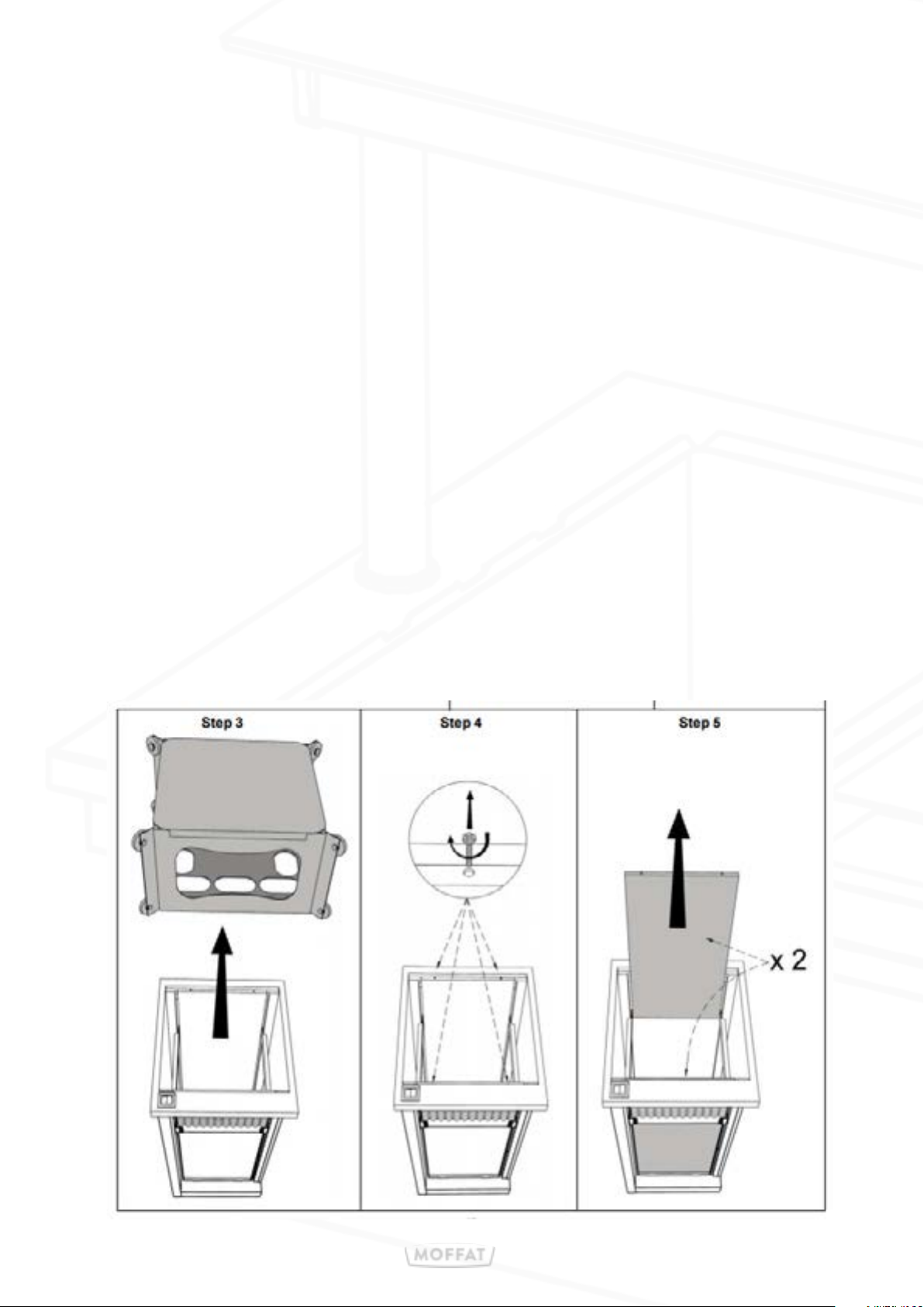
In order to access the tension springs the
Plate Base Support needs to be removed.
1. Remove lid & store in safe place.
2. Lift out plate/bowl carriage & store in safe place.
3. Unscrew the 4 bolts which secure the two inner panels and remove.
4. Adjust the springs (refer to page 21).
5. Relocate the inner panels. 2 Tabs on the bottom 2 screws on the top of each.
Page 21
10: Carvery station
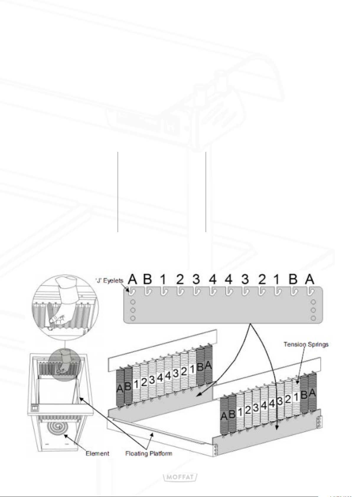
The ‘Floating Platform’ is supported by an equal amount of tension springs on each
corner. The number of springs equates to the size of plate being used.
Use the chart below as a starting point; add or remove springs accordingly
(in groups of four, one in each corner) until the top plate is at the required level).
The Springs are held in place using a hook & eye arrangement top & bottom.
They can be easily attached or detached by just hooking or unhooking the end in to
or out of the corresponding hole on the Floating support Arm.
Plate Diameter
8” (203mm)
9” (229mm)
10” (254mm)
11” (279mm)
12” (305mm)
Number of
Springs on
Each Corner
2
3
4
5
6
Total Number of
Springs
8
12
16
20
24
Page 22
11: Polar Well
Model
VC2PW
VC3PW
VC4PW
VC5PW
Weight
(kg)
58
87
117
145
Dimensions
L X W X H (mm)
830 x 680 x 900
1158 x 680 x 900
1486 x 680 x 900
1814 x 680 x 900
Electrical
Supply
13amp
13amp
13amp
13amp
Rating
(kw)
N/A
N/A
N/A
N/A
With Gantry
(kw)
0.23
0.27
0.32
0.37
Chilled Polar well display units with ambient storage cupboard.
Polar well models are designed to keep pre-chilled food cold using eutectic type polar
plates. Polar plates will keep food chilled for 2 to 3 hours. The polar plates must firstly
be charged for 8 to 12 hours in a deep freeze. If longer periods of operation are required extra polar plates can be charged in deep freeze and used in rotation.
Polar Plates weigh 5.5kg and can become slippery when wet.
Care should be taken when handling these units as they contain a liquid
refrigerant. The liquid that is sealed inside is free to move around and can
make lifting and handling awkward.
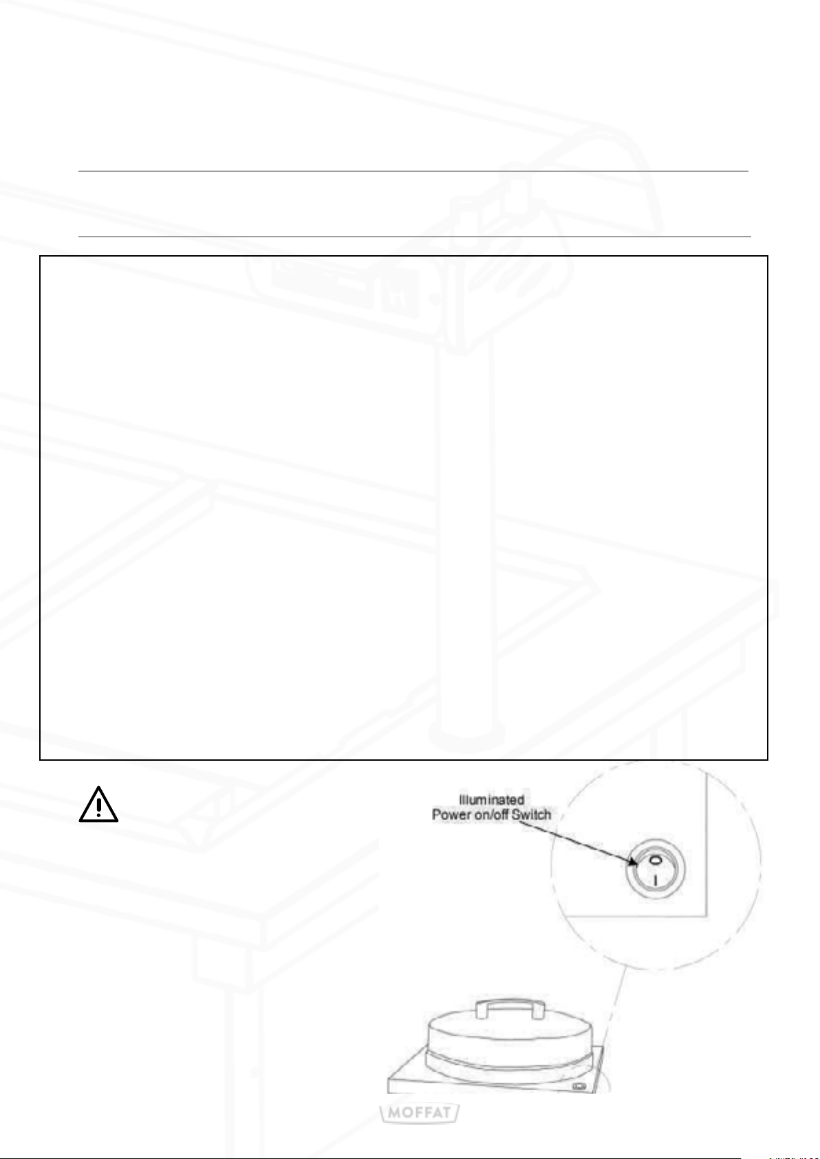
The Display unit is controlled by a green neon on/o switch
• Connect plug to 13-Amp socket and switch on at mains socket.
• Power on with green illuminated Switch
• When serving is complete all switches should be turned o.
• To maintain the life clean regularly with a damp cloth.
Page 23
12: Plate Dispenser
Model
VC2PDH
VC2PDA
Weight
(kg)
58
57
Dimensions
L X W X H (mm)
830 x 680 x 1046
830 x 680 x 950
Electrical
Supply
13amp
N/A
Rating
(kw)
1.20
N/A
In-counter spring-loaded pop-up plate dispensers Single or twin plate dispensers,
in both ambient & heated formats.
• Adjustable guides to suit 8” - 12” (203mm - 305mm) diameter plates.
• Variable spring system to accommodate dierent plate weights.
• Each tube can take a maximum of 65 plates (Depending on type of plate used).
Heated Models
• Thermostat controlled internal air temperature approximately 60°
• Complete with ergonomic black ABS plate cover.
• Supplied with a 2-meter cable fitted with a 13-amp molded plug for easy installation.
Operation:
• Load the Tube & cover plates with the supplied black ABS plate cover.
• Switch on the unit using the green switch.
• Allow approximately 60min to warm the plates before serving.
• When serving; remove the top plate & the plate below will automatically pop up.
These units will
remain hot for a long period of time after use
Page 24
12: Plate Dispenser
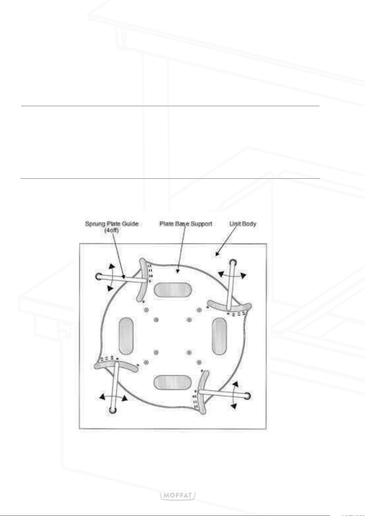
Setting the plate diameter by using one plate only,
set the guides to their correct positions for the size of plate.
Plate Diameter
8” (203mm)
9” (229mm)
10” (254mm)
11” (279mm)
12” (305mm
Plate Guide position
8
9
10
11
12
Page 25
12: Plate Dispenser
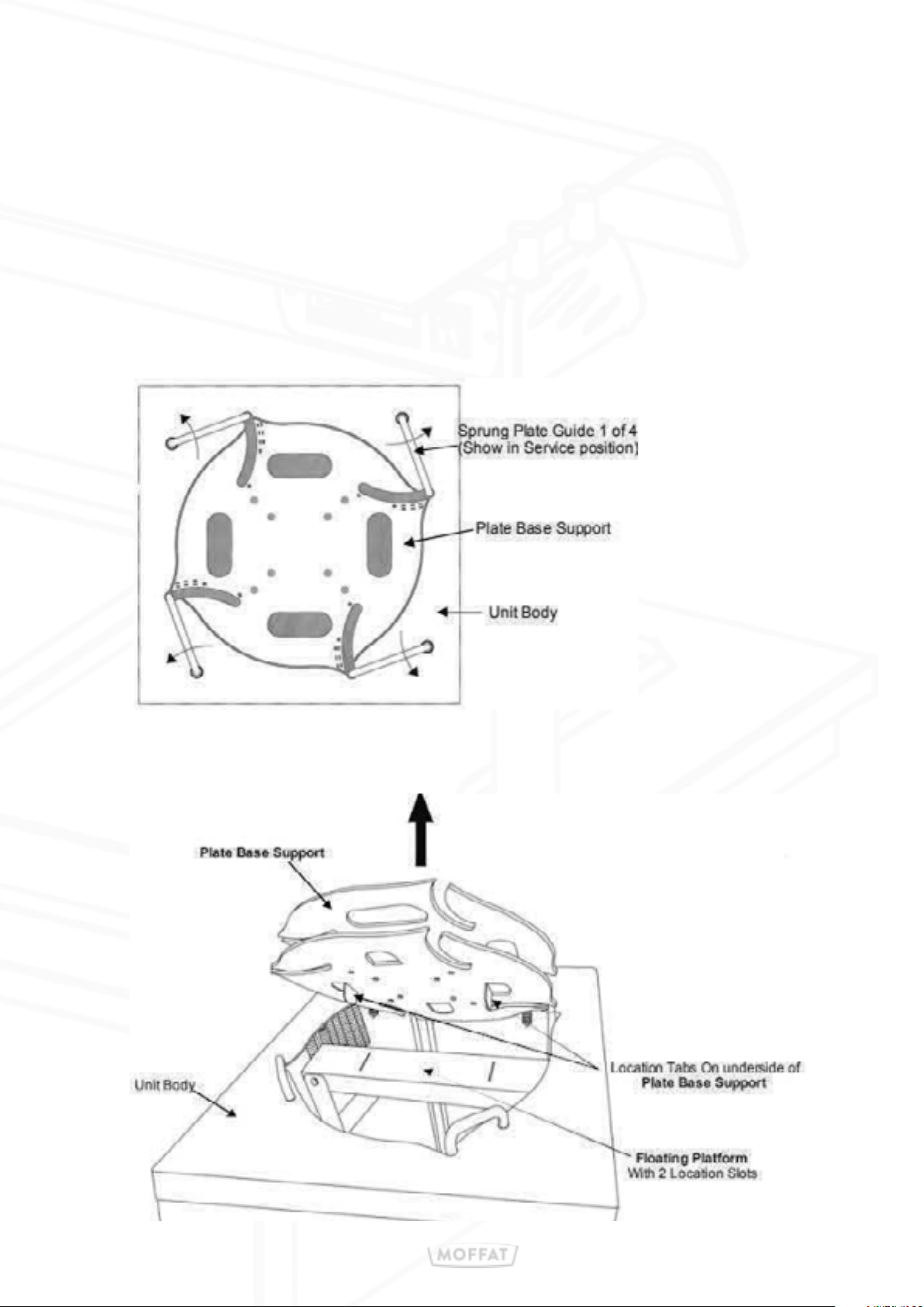
Setting the Spring Tension
Plates sits on a removable Plate Base Support which in turn rests on a floating platform.
This ‘Floating Platform’ in turn, is supported by several tension springs.
The tension springs are fastened symmetrically on two sides.
In order to access the tension springs the Plate Base Support needs to be removed.
1. Pull up the spring loaded ‘Plate Guides and swivel anticlockwise to their
extreme outer positions & lower down again for them to lock into
their ‘service’ positions.
2. Pull up the spring loaded ‘Plate Guides and swivel anticlockwise
to their extreme outer positions & lower down again for them to
lock into their ‘service’ positions.
Page 26
12: Plate Dispenser
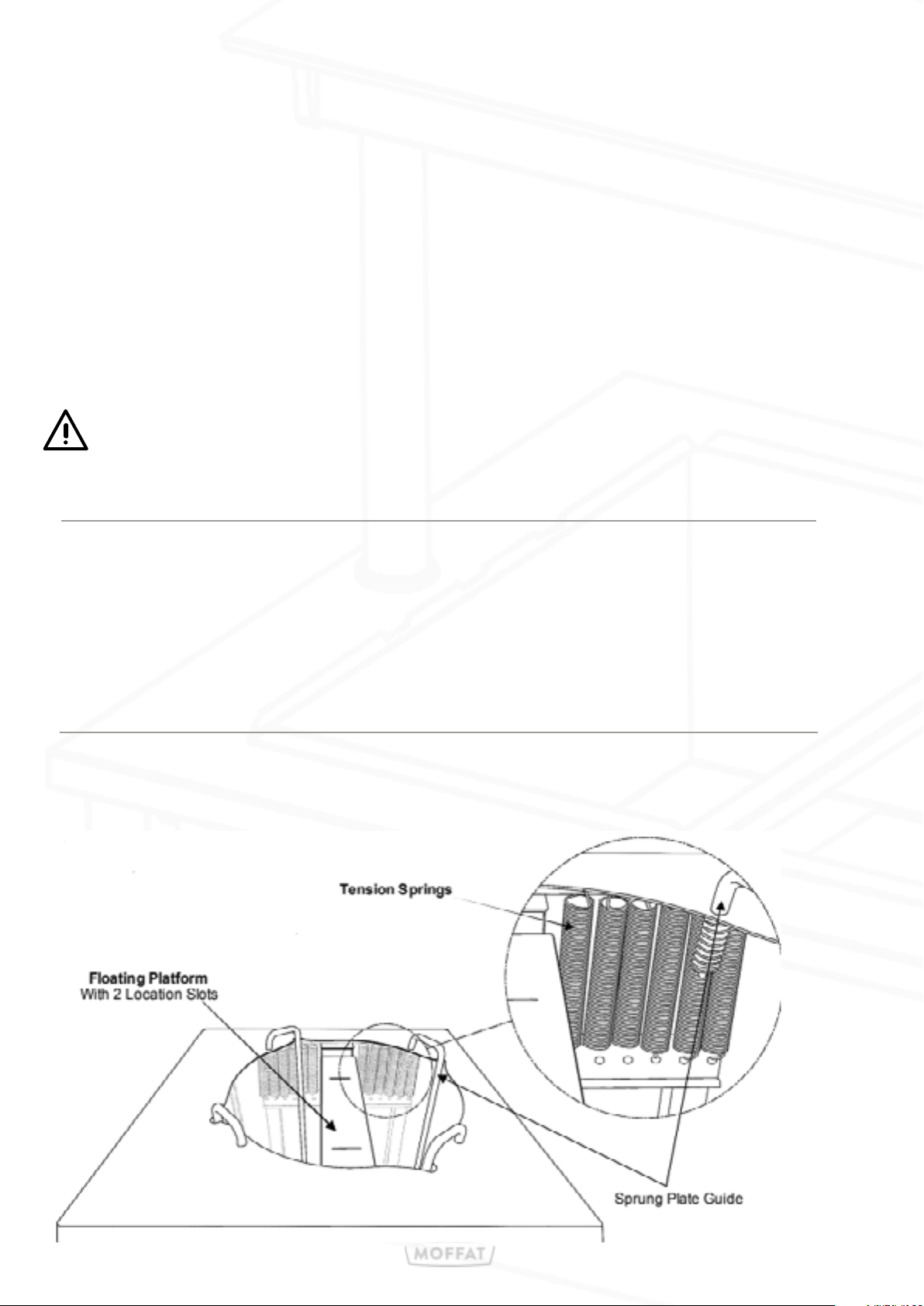
3. The ‘Floating Platform’ is supported by an equal amount of tension
springs on each corner.
The number of springs equates to the size of plate being used.
Use the chart below as a starting point; add or remove springs accordingly
(in groups of four, one each corner),
until the top plate is at the required serving level)
The Springs are held in place using a hook & eye arrangement top & bottom.
They can be easily attached or detached by just hooking or unhooking the end
in to or out of the corresponding hole on the Floating support Arm.
There must be an equal amount of springs on all four corners. The four corner
springs should not be removed. When removing springs, start from the centre
outwards. When adding springs work from the corners inwards. Keep the spring
numbers symmetrical whenever possible.
Plate Diameter
8” (203mm)
9” (229mm)
10” (254mm)
11” (279mm)
12” (305mm
Number of springs on each
corner
2
3
4
5
6
Total number of springs
8
12
16
20
24
Below shows the Plate lift set up for the weight of 9” Plates. Only the 3 outer springs are
attached to each corner of the Floating Platform. The 3 inner springs on the left, are shown in
their storage position. [hook on top only]
Page 27
13: Universal Crockery Dispenser
Model
VC2CDH
VC2CDA
Weight
(kg)
56
52
Dimensions
L X W X H (mm)
830 x 680 x 939
830 x 680 x 930
Electrical
Supply
13amp
N/A
Rating
(kw)
1.20
N/A
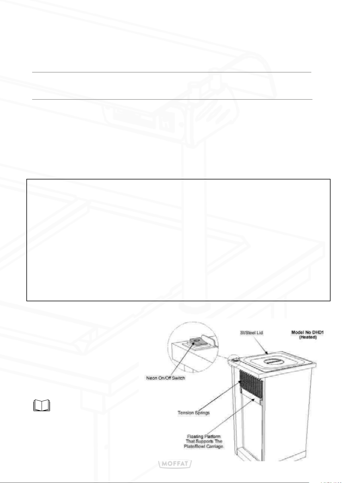
In-counter spring-loaded pop-up plate dispensers. Single tube in both ambient & heated formats.
Ideal for oval, round & square crockery including bowls up to 305mm (12”). bowl capacity may be
less depending on the type.
• Variable spring system to accommodate dierent plate weights.
• Each tube can take a maximum of 65 plates
(Depending on type of plate used).
Heated Models
• Thermostat controlled internal air temperature approximately 60°
• Complete with ergonomic stainless steel lid.
• Supplied with a 2-meter cable fitted with a 13-amp molded plug for easy installation.
Operation:
• Load the Tube & cover plates with the supplied stainless steel lid.
• Switch on the unit using the green switch.
• Allow approximately 60min to warm the plates before serving.
• When serving; remove the top plate & the plate below will automatically pop up.
See section 11 on page 20 and
21 for information on setting
the spring tension
Page 28
14: Quartz Lamp Replacement
Ensure appliance is disconnected from mains before servicing.
Lamps should not be touched with bare hands, as this may cause
premature failure. If lamp is touched, wipe clean with a cloth and
alcohol prior to use.
Replacement quartz lamps must never exceed the loading specified.
Wear safety glasses. Don’t touch hot halogen bulbs.
Only use replacement bulbs that match the wattage and design of the
fixture.
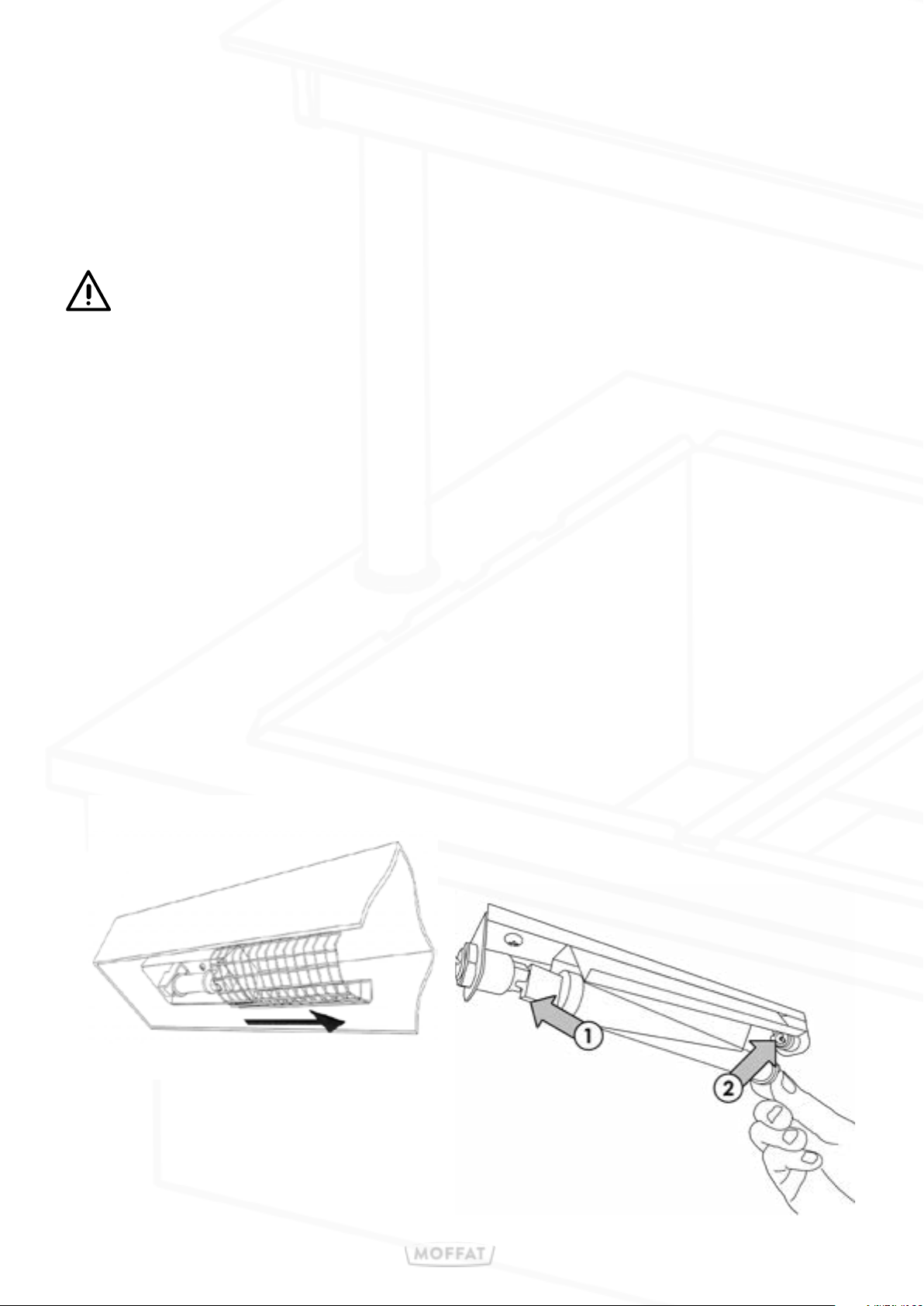
1. Isolate appliance from power supply and allow cooling
down before commencing lamp replacement.
2. Carefully slide mesh guard to one side until it clears the bulb area.
3. Remove faulty lamp by pushing to one side then pull down.
Hold the insulated end of the new lamp (Any end).
4. At a slight angle, slot the end of the new lamp into one of the Housing
5. Push against the sprung contact & hold it there.
6. Raise the opposite end of the lamp into the other end of the Lamp.
Page 29
15: Cleaning
Before attempting to clean the unit, please ensure that the Unit is
isolated from the electric supply and allowed to cool down, with all food
plates and other Dishes removed from the unit.
Do not use a water jet or pressure spray to clean this appliance.
1. Disconnect trolley from mains and wait until appliance has cooled.
2. Wipe clean using hot, soapy water and soft, non-abrasive cloth. Ensure
that the stainless steel is wiped in straight strokes following the grain of the
material.
11: Cleaning
3. Wipe dry using a clean cloth. Do not use scouring pads or abrasive cleaners
of any type. Shelving and select inner panels can be removed to allow a
deeper internal clean. Ensure all panels and fixings are replaced after cleaning
operation.
4. Refrigeration compartment should be washed and then dried with a cloth after
each service.
5. The chilled well has removable base sections for easy cleaning and
maintenance. They should be removed periodically and the area beneath wiped
clean.
6. The drain holes must also be kept clear from blockage.
7. Wipe down sneeze screen and glass top with a damp, clean cloth.
8. Finish by carefully drying with a soft dry cloth or Kitchen Towels.
Do not use scouring pads or abrasive cleaners of any type.
Do not use Solvents, bleach, Caustic Cleaners
or biological powders on any surface.
Special care should be taken around electrical parts,
avoided excessive use of water.
Take special care when cleaning glass use a soft duster & glass cleaner
spray.
Page 30
Thank you for choosing E&R Moat!
Scan the QR code below to visit the
E&R Moat website for further information:
E&R Moat Ltd.
Bonnybridge
FK4 2BS
Scotland
www.ermoat.co.uk
+44 (0) 1324 812272
sales@ermoat.co.uk
 Loading...