

Moffat RN8510GEC Installation Manual
Installation and Operation Manual
Gas Range Electric
Static/Convection Ovens
RN8510GE/GEC
RN8610GE/GEC
RN8810GE/GEC
Date Purchased
Serial Number
Dealer
Service Provider
For use in GB & IE
230562-8

MANUFACTURED BY
Moffat Limited
PO Box 10001
Christchurch
New Zealand
Ph: (03) 389 1007
Fax: (03) 389 1276
WORLD-WIDE BRANCHES
UNITED KINGDOM
Blue Seal
67 Gravelly Business Park
Gravelly Park
Birmingham
West Midlands
B24 8TQ
Ph: (121) 327 5575
Fax: (121) 327 9711
UNITED STATES
Moffat Inc
3765 Champion Blvd
Winston-Salem
North Carolina 27115
Ph: (336) 661 0257
Fax: (336) 661 9546
CANADA
Serve Canada
22 Ashwarren Road
Downview
Ontario M3J1Z5
Toll Free:800 263 1455
Ph: (416) 631 0601
Fax: (416) 631 0315
info@servecanada.com
www.servecanada.com
www.moffat.com
NEW ZEALAND
Christchurch
Moffat Limited Moffat Limited
PO Box 10-001 4 Waipuna Road
16 Osborne Street Mt Wellington
Christchurch Auckland
Ph: (03) 389 1007 Ph: (09) 574 3150
Fax: (03) 389 1276 Fax: (09) 574 3159
AUSTRALIA
Victoria
Moffat Pty Limited Moffat Pty Limited
740 Springvale Road 3/142 James Ruse Drive, Rose Hill
Mulgrave, Melbourne PO Box 913, Smithfield
Victoria 3171 Sydney, N.S.W. 2142
Ph: (03) 9518 3888 Ph: (02) 8833 4111
Fax: (03) 9518 3838 Fax: (02) 8833 4133
Western Australia
Moffat Pty Limited Moffat Pty Limited
67 Howe Street 30 Prosperity Place
Osbourne Park Geebung, Brisbane
WA 6017 Queensland 4034
Ph: (08) 9202 6820 Ph: (07) 3630 8600
Fax: (08) 9202 6836 Fax (07) 3630 8623
Auckland
New South Wales
Queensland
The reproduction or copying of any part of this manual by any means whatsoever is strictly forbidden unless authorized previously in
writing by the manufacturer.
In line with policy to continually develop and improve its products, Moffat Ltd. reserves the right to change the specifications and
design without prior notice.
© Copyright Moffat Ltd. January 2009.

Contents
Waldorf Gas Range Electric Static/Convection Ovens
RN8510GE Gas Range Electric Static Oven Four Open Burner.
RN8610GE Gas Range Electric Static Oven Six Open Burner.
RN8810GE Gas Range Electric Static Oven Eight Open Burner.
RN8510GEC Gas Range Electric Convection Oven Four Open Burner.
RN8610GEC Gas Range Electric Convection Oven Six Open Burner.
RN8810GEC Gas Range Electric Convection Oven Eight Open Burner.
Introduction .............................................................................................. 2
Specification .............................................................................................. 3
Model Numbers Covered in this Specification
General
Gas Supply Requirements
Gas Connection
Electrical Supply Requirements
Electrical Connection
Dimensions ................................................................................................ 6
Installation ................................................................................................ 9
Installation Requirements
Unpacking
Location
Clearances
Assembly
Fitting Rear Rollers
Gas Connection
Electrical Connection
Commissioning
Operation ................................................................................................. 14
Operation Guide
Description of Controls
Open Burners
Griddle
Oven
Cleaning and Maintenance ...................................................................... 18
General
After Each Use
Daily Cleaning
Weekly Cleaning
Periodic Maintenance
Fault Finding ............................................................................................ 22
Wiring Schematic..................................................................................... 24
Gas Conversion and Specifications.......................................................... 28
Conversion Procedure
Gas Specifications
Replacement Parts List............................................................................ 34
1
Introduction
We are confident that you will be delighted with your WALDORF GAS RANGE ELECTRICAL STATIC /
CONVECTION OVEN and it will become a most valued appliance in your commercial kitchen.
To ensure you receive the utmost benefit from your new Waldorf appliance, there are two important things
you can do.
Firstly:
Please read the instruction book carefully and follow the directions given. The time taken will be well
spent.
Secondly:
If you are unsure of any aspect of the installation, instructions or performance of your appliance,
contact your WALDORF dealer promptly. In many cases a phone call could answer your question.
CE Only:
These instructions are only valid if the country code appears on the appliance. If the code does not
appear on the appliance, refer to the supplier of this appliance to obtain the technical instructions for
adapting the appliance to the conditions for use in that country.
WARNING:
MPROPER INSTALLATION, ADJUSTMENT, ALTERATION, SERVICE OR MAINTENANCE CAN CAUSE PROPERTY
I
DAMAGE, INJURY OR DEATH. READ THE INSTALLATION, OPERATING AND MAINTENANCE INSTRUCTIONS
THOROUGHLY BEFORE INSTALLING OR SERVICING THIS APPLIANCE.
WARNING:
INSTRUCTIONS TO BE FOLLOWED IN THE EVENT THE USER SMELLS GAS ARE TO BE POSTED IN A PROMINENT
LOCATION. THIS INFORMATION SHALL BE OBTAINED BY CONSULTING THE LOCAL GAS SUPPLIER.
WARNING:
REAT CARE MUST BE TAKEN BY THE OPERATOR TO USE THE EQUIPMENT SAFELY TO GUARD IT AGAINST RISK
G
OF FIRE.
• T
• I
• DO NOT
•
HE APPLIANCE MUST NOT BE LEFT ON UNATTENDED.
T IS RECOMMENDED THAT A REGULAR INSPECTION IS MADE BY A COMPETENT SERVICEMAN TO ENSURE
CORRECT AND SAFE OPERATION OF YOUR APPLIANCE IS MAINTAINED.
STORE OR USE GASOLINE OR OTHER FLAMMABLE VAPOURS OR LIQUIDS IN THE VICINITY OF
THIS OR ANY OTHER APPLIANCE.
DO NOT SPRAY AEROSOLS IN THE VICINITY OF THIS APPLIANCE WHILE IT IS IN OPERATION.
C
AUTION
:
This appliance is;
•
For professional use and is to be used by qualified persons only.
•
Only qualified service persons are to carry out installation, servicing and
gas conversion operations.
•
Components having adjustments protected (e.g. paint sealed) by the
manufacturer should not be adjusted by the user / operator.
•
DO NOT operate the appliance without the legs supplied fitted.
2

Model Numbers Covered in this Specification
RN8510GE 4 Open Burners + Electric Static Oven.
RN8513GE 2 Open Burners + 300mm Griddle + Electric Static Oven.
RN8610GE 6 Open Burners + Electric Static Oven.
RN8613GE 4 Open Burners + 300mm Griddle + Electric Static Oven.
RN8616GE 2 Open Burners + 600mm Griddle + Electric Static Oven.
RN8619GE 900 mm Griddle + Electric Static Oven.
RN8810GE 8 Open Burners + Electric Static Oven.
RN8813GE 6 Open Burners + 300mm Griddle + Electric Static Oven.
RN8816GE 4 Open Burners + 600mm Griddle + Electric Static Oven.
RN8819GE 2 Open Burners + 900mm Griddle + Electric Static Oven.
RN8510GEC 4 Open Burners + Electric Convection Oven.
RN8513GEC 2 Open Burners + 300mm Griddle + Electric Convection Oven.
RN8610GEC 6 Open Burners + Electric Convection Oven.
RN8613GEC 4 Open Burners + 300mm Griddle + Electric Convection Oven.
RN8616GEC 2 Open Burners + 600mm Griddle + Electric Convection Oven.
RN8619GEC 900 mm Griddle + Electric Convection Oven.
RN8810GEC 8 Open Burners + Electric Convection Oven.
RN8813GEC 6 Open Burners + 300mm Griddle + Electric Convection Oven.
RN8816GEC 4 Open Burners + 600mm Griddle + Electric Convection Oven.
RN8819GEC 2 Open Burners + 900mm Griddle + Electric Convection Oven.
General
Specifications
A heavy duty, general purpose gas range created for compact modular kitchens. It has a high option
Cook Top / Griddle arrangement and is available on industrial adjustable feet or on robust rollers.
Open Burners are available in either 'PF' (Pilot and Flame Failure) or 'F' (Flame Failure Only) options.
Open Burner and Griddle options are fitted with individual flame failure for each open burner.
Griddles are fitted with pilot, flame failure and piezo ignition as standard. Easy clean stainless steel
external finish.
Easy clean stainless external finish.
3
Specifications
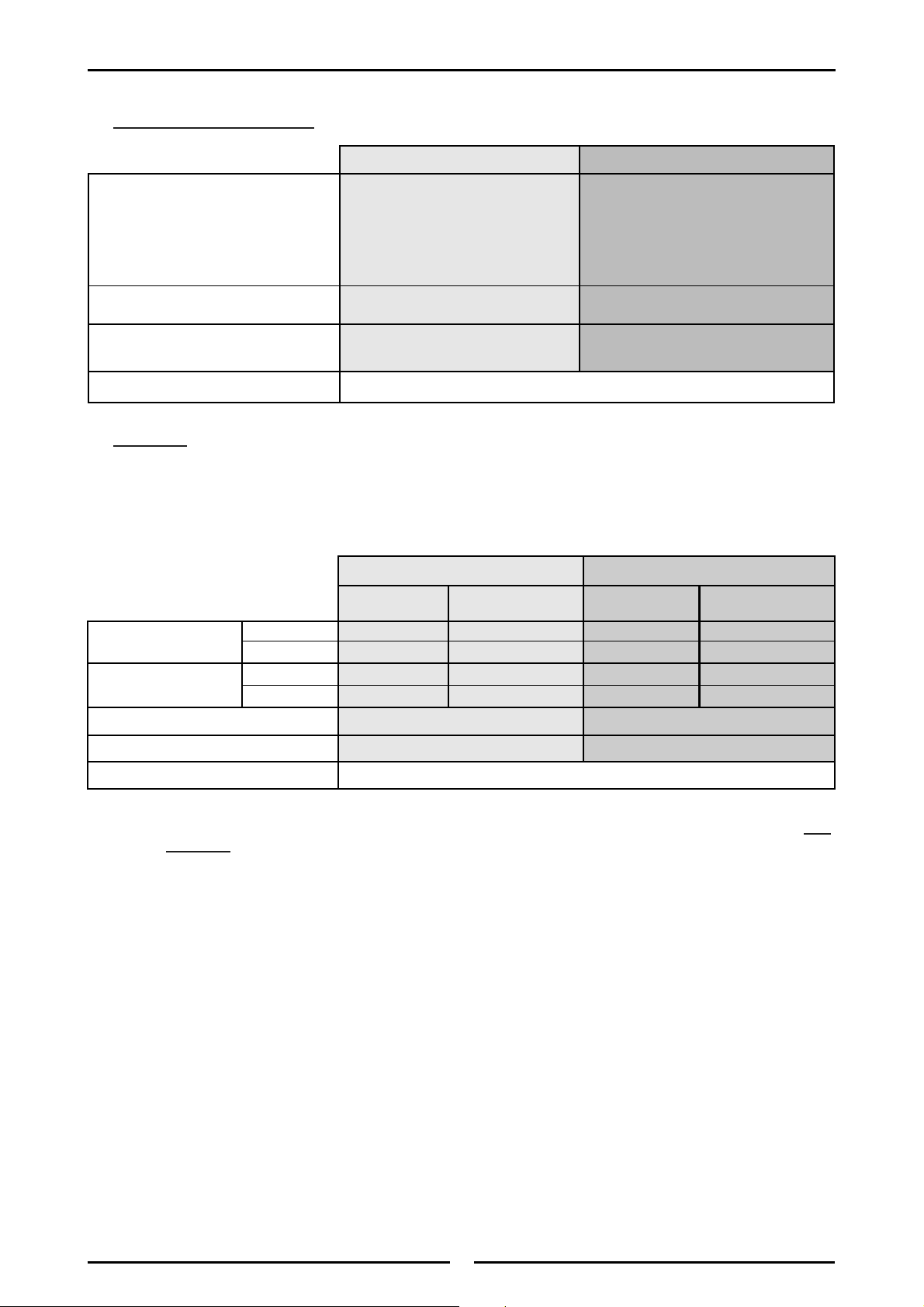
Gas Supply Requirements
- Australia / New Zealand
Input Rate (N.H.G.C.)
- each Open Burner
- each 300 mm Griddle Section
Supply Pressure
Operating Pressure
Gas Connection
Natural Gas LP Gas (Propane)
28 MJ/hr
(26,540 Btu/hr)
21 MJ/hr
(19,900 Btu/hr)
1.13 - 3.40 kPa
(4.5” - 13.5” w.c.)
0.95 kPa (*)
(3.7” w.c.)
3
/4” B.S.P. Male
28 MJ/hr
(26,540 Btu/hr)
21 MJ/hr
(19,900 Btu/hr)
2.75 - 4.50 kPa
(11” - 18.0” w.c.)
2.6 kPa (*)
(10.0” w.c.)
- UK Only
Appliance Classification
Category: II
2H3P.
Flue Type: A1.
Natural Gas (G20) Propane (G31)
Heat Input
(nett)
Gas Rate (nett)
Nominal 6.5 kW 5.5 kW 6.5 kW 5.5 kW
Reduced 1.75 kW 1.85 kW 1.75 kW 1.95 kW
Nominal 0.69 m3/hr 0.58 m3/hr 0.51 kg/hr 0.43 kg/hr
Reduced 0.19 m3/hr 0.20 m3/hr 0.14 kg/hr 0.15 kg/hr
Open Burner
(each)
Griddle
(each 300mm section)
Open Burner
(each)
(each 300mm section)
Supply Pressure 20 mbar 37 mbar
Griddle
Burner Operating Pressure 9.5 mbar (*) 26 mbar (*)
Gas Connection See ‘Gas Connection’ information overleaf
* The burner operating pressure is to be measured at the manifold test point with two
burners operating at full setting. The operating pressure is ex-factory set, through the
appliance regulator and is not to be adjusted, apart from when carrying out gas
conversion, if required. (Refer to the ‘Gas Conversion’ section for details).
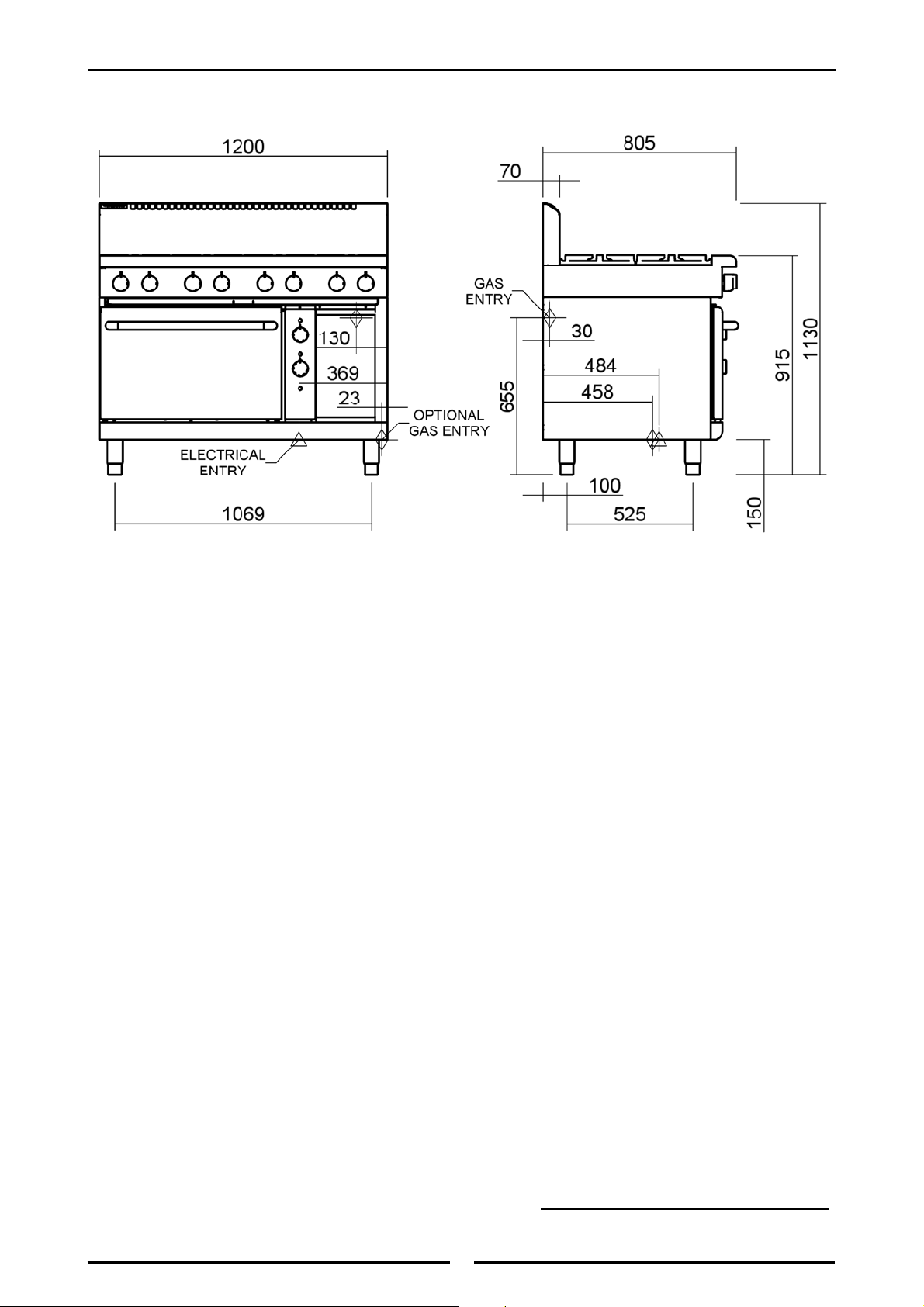
Gas Connection
Gas supply connection point is located at the rear of the appliance, approximately 130mm from the
right hand side, 35mm from the rear and 655mm from the floor and is reached from beneath the
appliance. (Refer to the ‘Dimensions’ section).
Connection is ¾" BSP male thread.
4

Electrical Supply Requirements
Specifications
MODEL
RN8510GE
RN8510GEC
RN8610GE
RN8610GEC
RN8810GE
RN8810GEC
1-Phase Connection
1P+N+E
230-240V
5.5 kW,
22.6 Amps @ 235 V
5.8 kW,
23.9 Amps @ 235 V
6.5 kW,
26.6 Amps @ 235 V
6.8 kW,
27.9 Amps @ 235 V
6.5 kW,
26.6 Amps @ 235 V
6.8 kW,
27.9 Amps @ 235 V
3-Phase Connection
3P+N+E
400-415V
5.5 kW
5.8 kW
6.5 kW
6.8 kW
6.5 kW
6.8 kW
L1 - 7.2 Amps
L2 - 7.7 Amps
L3 - 7.7 Amps
L1 - 8.5 Amps
L2 - 7.7 Amps
L3 - 7.7 Amps
L1 - 8.2 Amps
L2 - 9.2 Amps
L3 - 9.2 Amps
L1 - 9.5 Amps
L2 - 9.2 Amps
L3 - 9.2 Amps
L1 - 8.2 Amps
L2 - 9.2 Amps
L3 - 9.2 Amps
L1 - 9.5 Amps
L2 - 9.2 Amps
L3 - 9.2 Amps
Electrical Connection
WARNING:
HIS APPLIANCE MUST BE EARTHED. IF THE SUPPLY CORD IS DAMAGED, IT MUST BE REPLACED BY A SUITABLY
T
QUALIFIED PERSON IN ORDER TO AVOID A HAZARD.
RN8510 / RN8610GE / GEC Models Only
.
Electrical supply connection point is located at the rear of the appliance, approximately 69mm from
the right hand side and 484mm from the rear and 150mm from the floor.
RN8810GE / GEC Models Only
.
Electrical supply connection point is located at the rear of the appliance, approximately 69mm from
the right hand side, 484mm from the rear and 150mm from the floor.
When connecting a this electric appliance to the mains supply, ensure that the following is carried
out:-
• An isolating switch is fitted within 2 m of the appliance, but not on the appliance and in
such a position that the user does not have to reach across the cooking surface.
• Supply cord shall be oil-resistant, sheathed flexible cable and not lighter than ordinary
polychloroprene or other equivalent synthetic elastomer sheathed cord (as per AS / NZS
3191 part 2.10.11. or IEC 60245-IEC-57) e.g. HO5 RN-F Type.
• The branch supply line shall be individually overload protected to the correct current rating
and the supply chord shall be protected against any mechanical or thermal damage.
• A grommet is fitted around the wiring entry hole into the appliance.
• All wiring connections must be tight.
Refer to the appropriate wiring standards for the size of cable that is to be supplied to an appliance
for the current drawn on that line.
5
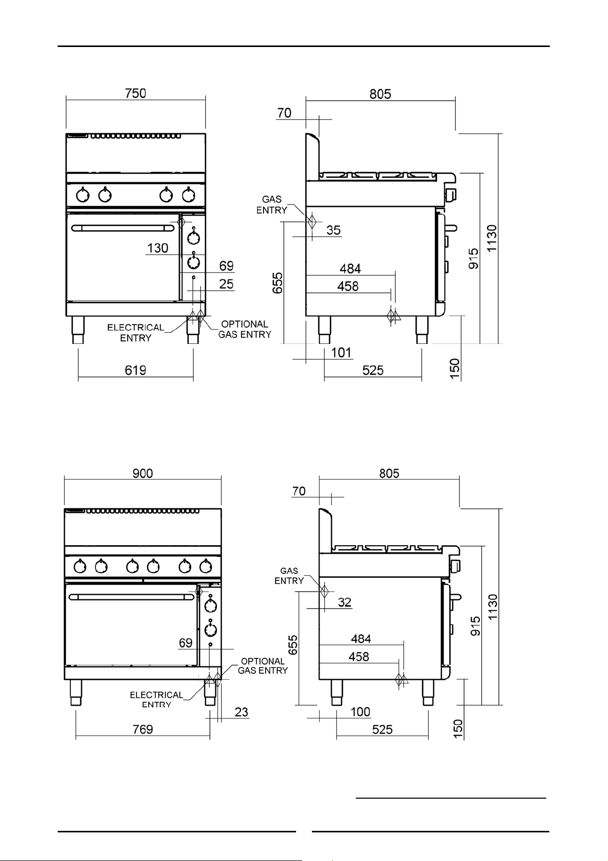
Dimensions
Dimensions RN8510GE / GEC
Dimensions RN8610GE / GEC
6
Refer to Page 8 for Cook Top Options
Dimensions RN8810GE / GEC
Dimensions
7
Refer to Page 8 for Cook Top Options
Dimensions
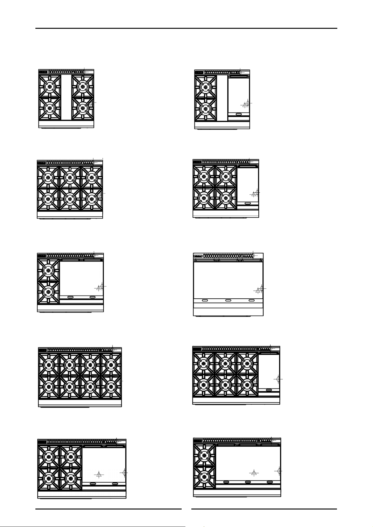
Cook Top Options
Cook Top Options RN8510GE / GEC
Cook Top Options RN8610GE / GEC
Cook Top Options RN8513GE / GEC
Cook Top Options RN8613GE / GEC
Cook Top Options RN8616GE / GEC
Cook Top Options RN8810GE / GEC
Cook Top Options RN8619GE / GEC
Cook Top Options RN8813GE / GEC
Cook Top Options RN8816GE / GEC
Cook Top Options RN8819GE / GEC
8

Installation
Installation Requirements
NOTE:
• It is most important that this appliance is installed correctly and that operation is correct
before use. Installation shall comply with local electrical, gas, health and safety
requirements.
• This appliance shall be installed with sufficient ventilation to prevent the occurrence of
unacceptable concentrations of health harmful substances in the room, the appliance is
installed in.
Waldorf Convection Ovens are designed to provide years of satisfactory service, and correct installation is
essential to achieve the best performance, efficiency and trouble-free operation.
This appliance must be installed in accordance with National installation codes and in addition, in
accordance with relevant National / Local codes covering gas, electrical and fire safety.
Australia: - AS5601 - Gas Installations.
New Zealand: - NZS5261 - Gas Installation.
Australia / New Zealand: - AS / NZS3000 - Wiring Rules.
United Kingdom: - Gas Safety (Installation & Use) Regulations 1998.
- BS6173 - Installation of Catering Appliances.
- BS5440 1 & 2 - Installation Flueing & Ventilation.
- BS7671 - Requirements for Electrical Installation.
Ireland: - IS 820 - Non - Domestic Gas Installations.
Installations must be carried out by qualified persons only. Failure to install equipment to the
relevant codes and manufacturer’s specifications shown in this section will void the
warranty.
Components having adjustments protected (e.g. paint sealed) by the manufacturer are only
allowed to be adjusted by an authorised service agent. They are not to be adjusted by the
installation person.
Unpacking
• Remove all packaging and transit protection from the appliance including all protective plastic
coating from the exterior stainless steel panels.
• Check equipment and parts for damage. Report any damage immediately to the carrier and
distributor.
• Report any deficiencies to the distributor who supplied the appliance.
• Check that the available gas and electrical supply is correct to that shown on the rating plate located
on the front right hand corner of the bottom sill.
Location
1. Installation must allow for a sufficient flow of fresh air for the combustion air supply.
Combustion Air Requirements:
RN8510GE / GEC RN8610GE / GEC RN8810GE / GEC
Natural Gas (G20) 29 m3/hr 44 m3/hr 58 m3/hr
3
LPG (G31) 30 m
/hr 45 m3/hr 60 m3/hr
2. Installation must include adequate ventilation means, to prevent dangerous build up of combustion
products.
3. Never directly connect a ventilation system to the appliance flue outlet.
4. Position the appliance in its approximate working position.
5. All air for burner combustion is supplied from underneath the appliance. The legs must always be
fitted and no obstructions placed on the underside or around the base of the appliance, as
obstructions will cause incorrect operation and / or failure of the appliance.
NOTE: Do not obstruct or block the appliances flue. Never directly connect a ventilation
system to the appliance flue outlet.
9
Installation
Clearances
NOTE: Only non-combustible materials can be used in close proximity to this appliance.
Combustible Surface Non Combustible Surface
Left / Right hand side 250mm (*) 0mm
Rear 50mm 0mm
* Side clearances can be 50mm when the adjacent surface is at least 100mm below the cooking
surface.
Assembly
This model is delivered completely assembled. Ensure that the legs are securely attached.
NOTE:
• This appliance is fitted with adjustable feet to
enable it to be positioned securely and level on
uneven floors. This should be carried out on
completion of the gas connection. Refer to the
'Gas Connection Section'.
• This appliance can also be fitted with rear rollers to
enable the appliance to be easily moved for
positioning and cleaning purposes. If desired,
these rollers are supplied in the packaging, with
the appliance. See below for fitting instructions.
Optional Accessories (Refer to Replacement Parts
List)
• Plinth Kit. For installation details, refer to the
instructions supplied with each kit.
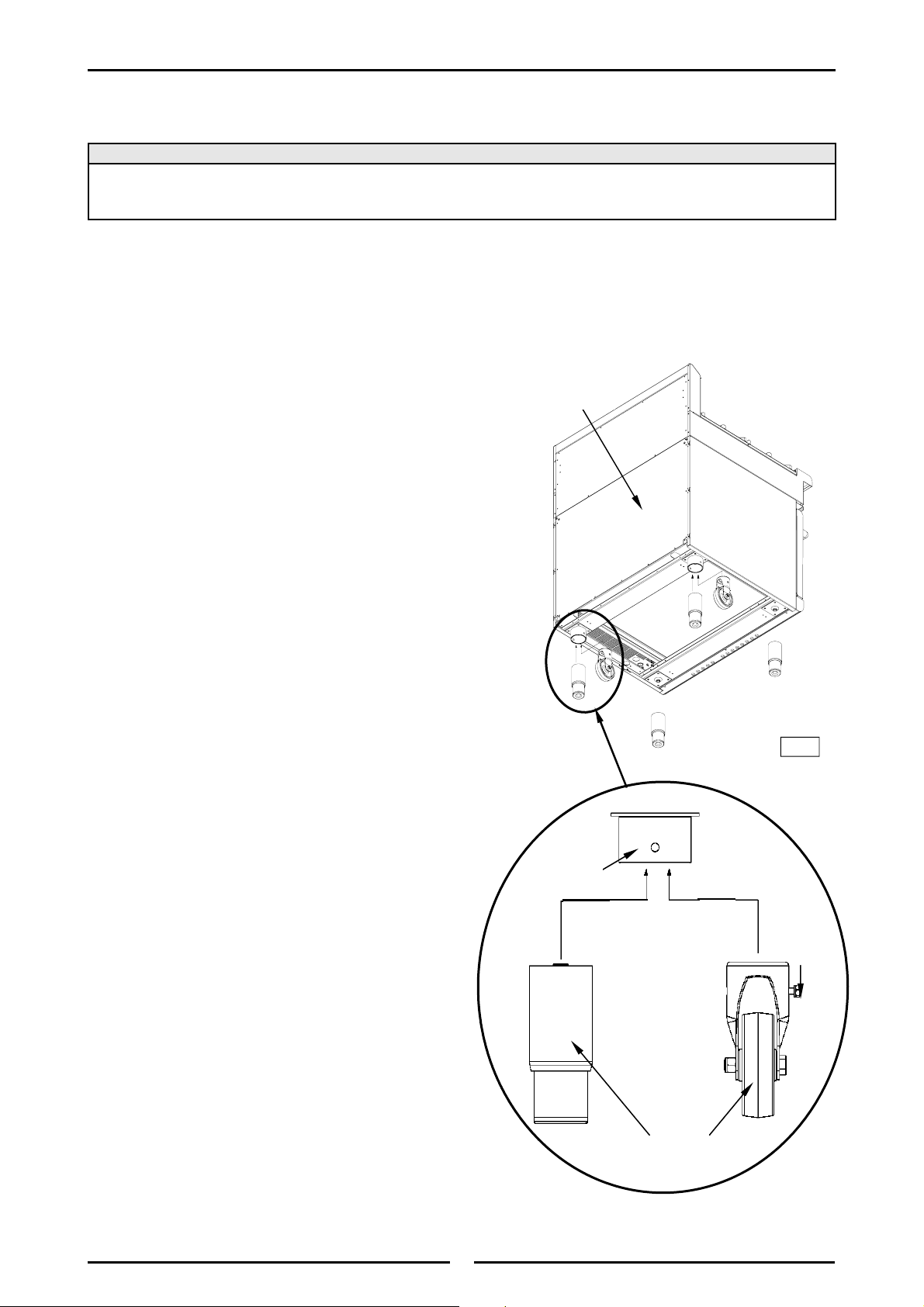
Fitting Rear Rollers.
1. Raise the appliance from the floor by approx.
75mm using suitable lifting equipment (i.e.
Palletiser / Forklift) to allow the rear adjustable
feet to be removed.
2. Unscrew and remove both the rear adjustable
feet from the rear leg housings.
3. Fit the rear roller to the rear leg housing and
align the screw hole in the side of the rear leg
housing with the threaded hole in the rear
roller.
4. Secure the rear roller to the leg support with
the bolt supplied and tighten the bolt using a
10mm A/F spanner.
5. Fit the second roller and tighten.
6. Lower the appliance back to the floor and
adjust the front adjustable feet to level the
appliance.
Appliance
Base
Rear Leg
Housing
Fig 1
Roller
Locating Bolt
10
Adjustable
Foot
Rear Roller
Assy
 Loading...