

Page 1

30D
SERIES
G32D4/D5
(Digital Operation)
Service Manual
11 May 2015
Amendment 10
Page 2

MANUFACTURED BY
Moffat Limited
Rolleston 7675
New Zealand
INTERNATIONAL CONTACTS
AUSTRALIA
Moffat Pty Limited
Web: www.moffat.com.au
E.Mail: vsales@moffat.com.au
Main Office: (tel) +61 (03) 9518 3888
(fax) +61 (03) 9518 3833
Service: (tel): 1800 622 216
Spares: (tel): 1800 337 963
Customer Service: (tel): 1800 335 315
(fax): 1800 350 281
CANADA
Serve Canada
Web: www.servecanada.com
E.Mail: info@servecanada.com
Sales: (tel): 800 551 8795 (Toll Free)
Service: (tel): 800 263 1455 (Toll Free)
NEW ZEALAND
Moffat Limited
Web: www.moffat.co.nz
E.Mail: sales@moffat.co.nz
Main Office: (tel): 0800 663328
UNITED KINGDOM
Blue Seal
Web: www.blue-seal.co.uk
E.Mail: sales@blue-seal.co.uk
Sales: (tel): +44 121 327 5575
(fax): +44 121 327 9711
Spares: (tel): +44 121 322 6640
(fax): +44 121 327 9201
Service: (tel): +44 121 322 6644
(fax): +44 121 327 6257
UNITED STATES
Moffat
Web: www.moffat.com
Sales: (tel): 800 551 8795 (Toll Free)
Service:
REST OF WORLD
Moffat Limited
Web: www.moffat.co.nz
E.Mail: export@moffat.co.nz
(tel): +1 336 661 1556
(fax): +1 336 661 9546
(tel): 866 673 7937 (Toll Free)
(tel): +1 336 661 1556
(fax): +1 336 661 1660
The reproduction or copying of any part of this manual by any means whatsoever is strictly forbidden unless authorized previously in writing
by the manufacturer.
In line with policy to continually develop and improve its products, Moffat Ltd. reserves the right to change the specifications and design
without prior notice.
© Copyright Moffat Ltd. May 2015.
11 May 2015
Amendment 10
Page 3

Contents List
G32 Turbofan Convection Oven.
Model Numbers Covered in this Manual
G32D4 - Turbofan Oven - 4 Tray Convection Oven.
G32D5 - Turbofan Oven - 5 Tray Convection Oven.
Specifications ........................................................................................................................... 2
Installatio n ............................................................................................................................... 4
Installation Requirements
Unpacking
Location
Clearances
Stand Mounted Ovens
Electrical Connection
Gas Connection
Recommended Water Specifications
Water Connection
Positioning and Levelling of Oven
Stand Mounted Ovens
Initial Start-Up
Commissioning
Operation .................................................................................................................................. 7
Oven Control Panel (Up to Ser. No. 762119)
Oven Control Panel (From Ser. No. 762120)
Changing Operator Settings
Operator Settings
Parts Replacement ................................................................................................................. 10
5.1 Parts Replacement
5.2 Adjustment and Calibration
Controller Programming ........................................................................................................ 22
6.1 Viewing / Changing Service Parameters
6.2 Viewing / Changing Service Parameters (Up to Ser No. 762119)
6.3 Viewing / Changing Service Parameters (From Ser No. 762120)
E
Wiring Diagrams..................................................................................................................... 2
Exploded Parts Lists ............................................................................................................... 2
Accessories ............................................................................................................................ 3
Gas Conversion and S
Appendix 1 - Oven Door Reversal ........................................................................................... 39
WARNING:
11 May 2015
lectrical Schematics ............................................................................................................. 26
7
9
6
pecifications ........................................................................................ 37
ALL INSTALLATION AND SERVICE REPAIR WORK MUST BE CARRIED OUT BY QUALIFIED PERSONS ONLY.
IMPROPER INSTALLATION, ALTERATION, ADJUSTMENT, MAINTENANCE OR SERVICE MAY CAUSE PROPERTY
DAMAGE, INJURY OR DEATH.
ENSURE ELECTRIC AND GAS SUPPLIES ARE TURNED OFF BEFORE SERVICING.
ALWAYS TEST AFTER SERVICE REPAIRS
Amendment 10
Page 4
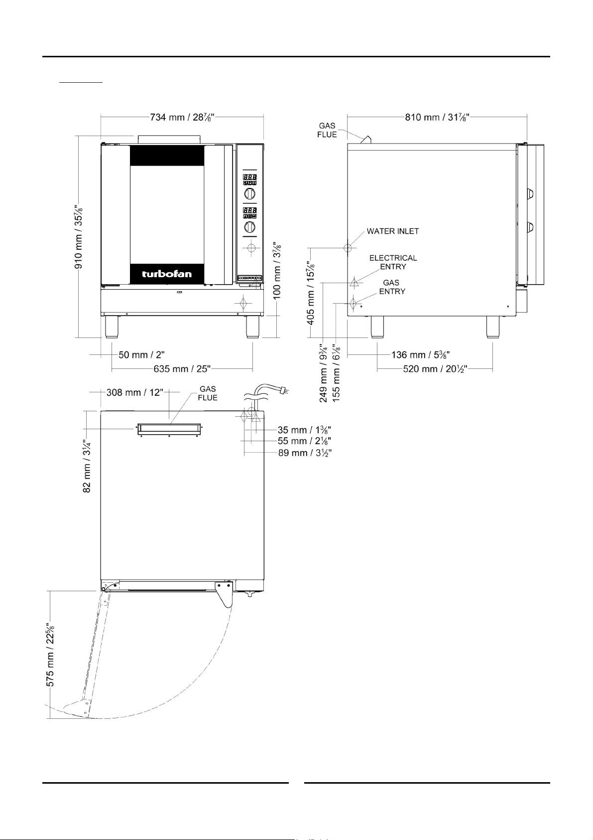
1 Specifications
G32D4/D5
11 May 2015
2
Amendment 10
Page 5
Oven Gas Supply Requirements and Specifications
G32D5 (110 - 120V):
Natural Gas LP Gas
Input Rating 35 MJ/hr. 35 MJ/hr.
Supply Pressure
1.75 kPa. 2.75 kPa.
Operating Pressure 1.05 kPa. 2.75 kPa.
Gas Connection ½” NPT.
Electrical Power Ratings 1 Phase, 110-120V, 60HZ, 220W.
Oven Tray Details
Water Connection
Tray Capacity
Tray Spacing
5 x US Full Pan.
85mm / 31/3”.
¾” BSP with ¾” GHT Adaptor supplied (80 psi / 550 kPa
maximum pressure).
Specifications 1
G32D4 (
240V) - UK Only:
Category: II
Flue Type: A
2H3P.
1.
Natural Gas Propane
Input Rating 10 kW 10 kW
Supply Pressure 20 mbar 30 - 37 mbar
Operating Pressure 10 mbar 25 mbar
Gas Connection ½” BSP Male.
Electrical Power Ratings 220-240V, 1P+N+E, 50/60HZ, 200W.
4, 18” x 26” / 460 x 660 Full Size Sheet Pan Capacity.
4, 600 x 400 Tray Capacity.
110mm.
Oven Tray Details
Tray Capacity
Tray Spacing
Water Connection ¾” BSP (80 psi / 550 kPa maximum pressure).
G32D4 (
220 - 240V) - All Other Markets:
Natural Gas LP Gas (Propane)
Input Rating 35 MJ/hr. 35 MJ/hr.
Supply Pressure 1.13 - 3.4 kPa. 2.75 - 5.0 kPa.
Operating Pressure 0.75 kPa. 2.35 kPa.
Gas Connection ½” BSP Male.
Electrical Power Ratings 220-240V, 1P+N+E, 50/60HZ, 200W.
Oven Tray Details
Tray Capacity
Tray Spacing
4 x US Full Pan / EN 600 x 400.
110mm.
Water Connection ¾” BSP (80 psi / 550 kPa maximum pressure).
11 May 2015
3
Amendment 10
Page 6
2 Installation
Installation Requirements
Important:
Installation shall comply with local gas, electrical and health and safety requirements.
It is most important that this oven is installed correctly and that oven operation is correct before use.
If you have any questions regarding the proper installation and / or operation of this oven, please contact your local
Turbofan distributor.
This installation of this appliance must conform with local codes, or in the absence of local codes, must conform to the National Codes shown
below covering gas and electrical safety.
Australia: - AS5601 - Gas Installations.
New Zealand: - NZS5261 - Gas Installation.
Australia / New Zealand: - AS/NZS3000 - Wiring Rules.
United Kingdom: - Gas Safety (Installation & Use) Regulations 1998.
Ireland: - IS 820 - Non - Domestic Gas Installations.
- BS6173 - Installation of Catering Appliances.
- BS5440 1 & 2 - Installation Flueing & Ventilation.
- BS7671 - Requirements for Electrical Installations.
Installation
Installations must be carried out by authorised persons only.
Failure to install equipment to the relevant codes and
manufacturers specifications shown above, will void the warranty.
This oven must be electrically earthed / grounded in accordance
with local codes.
Installation must allow for a sufficient flow of fresh air for the
combustion air supply. Combustion air requirements:
Natural Gas 10m³/hr.
LPG
Components having adjustments protected (e.g. paint sealed) by
manufacturer are only to be adjusted by an authorised service
agent. They are not to be adjusted by the installation person.
9m³/hr.
Unpacking
1. Remove all packaging and transit protection including all
protective plastic coating from the exterior stainless steel
panels.
2. Check the oven and supplied parts for damage. Report any
damage immediately to the carrier and distributo
3.
Check that the following parts have been supplied with yo
oven:
-
4 x Leg Adjustable.
Adaptor Brass.
Rubber Washer.
4. Report any deficiencies to the distributor who supplied yo
oven.
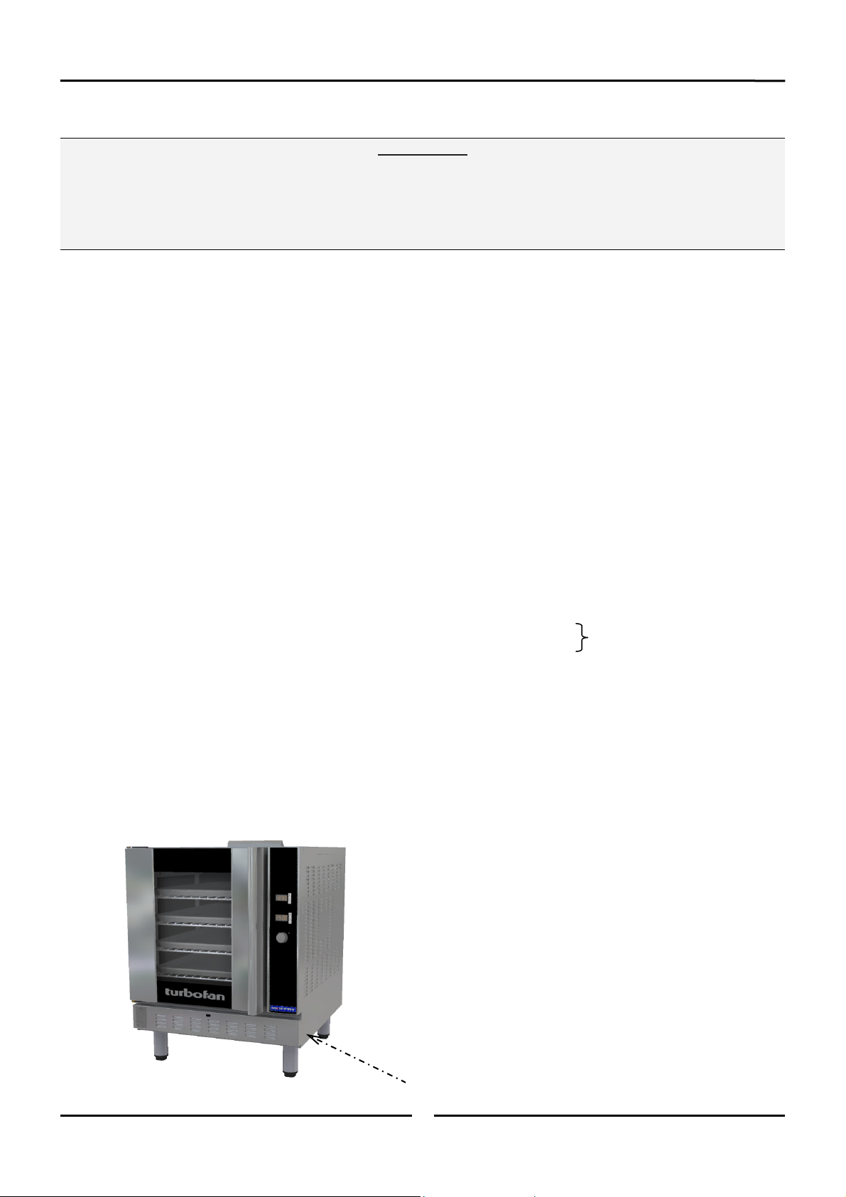
Securely fit the 4 legs supplied with the ov
5.
Check that the available gas and electrical supply is correct to
6.
that shown on the Technical Data Plate located on the fron
ri
ght hand side panel.
USA / Canada Only)
r.
en.
Refer to ‘Specifications’ section, ‘Oven
Specifi
cations Tables’.
ur
ur
t
11 May 2015
Technical Data Plate - Location
4
Amendment 10
Page 7
Installation 2
Location
1. This oven must be installed in an area of adequate air supply.
Adequate ven
of combustion products. DO NOT obstruct the
up
around
2. This oven must be fitted on supplied legs in all installations.
(When installed on a manufacturers stand, the le
to l
ocate the oven in the correct position.
3. All air for burner combustion is supplied from beneat
iance. Legs must always be fitted and no obstructions
appl
placed beneath or around the base of the applianc
structions will cause incorrect operation and / or failure
ob
the ap
4
. Installation must allow for a sufficient flow of fresh
ombustion air supply.
c
The area around the appliance must be kept free and cl
5.
from comb
6. Position the oven in its approximate working positi
should be positioned so that the control panel and ov
It
shelve
7
. Use a spirit level to ensure oven is level from side to si
t to back. (If this is not carried out, uneven cooking could
fron
occur).
The vent located on the top of the oven must NOT be
obstructed.
tilation is essential, to prevent dangerous buil
the ventilation slots.
gs are used
e.
plianc
ustibles.
s are easily reachable for loading and unloadi
Important:
Oven Vent
e, as
on.
d
air flow
h the
of
air for the
ear
en
ng.
de and
Electrical Connection
Warning
s oven must be earthed / grounded.
Thi
h oven should be connected to an adequately protected power
Eac
supply and an isolation switch mounted adjacent to, but not
behind the oven and must be readily accessible to the operator.
This switch must be clearly marked and readily accessible in case
of fire.
Check the electricity supply is correct to as shown on the
Technical Data Plate on the front right hand corner of the oven
side panel.
Ensure that the oven is fitted with the appropriate power cord and
plug.
Gas Connection
A ½" BSP or ½" N.P.T connection is provided at the bottom rear
of the oven.
A restraint chain anchor has been provided below the gas
connection point on the appliance, for fitment of a restraint chain.
It is important that adequately sized piping run directly to the
connection joint on the oven with as few tees and elbows as
possible to give maximum supply volume.
A suitable jointing compound which resists the break down action
of LPG must be used on every gas connection.
Check all gas connections for leakages using soapy water or other
gas detecting equipment.
Clearances
1. To ensure correct ventilation for the motor and controller, the
lowing minimum installation clearances are to be adhered
fol
to:
CLEARANCE FR
A minimum distance of 300mm (12”) from appliance sides
is required.
Top 600mm/24” 200mm/8”
Left / Right
Hand Side
Rear 75mm/3” 75mm/3”
NOTE: Fixed installations require at least 500mm clearance
OM SOURCE OF HEAT.
Combustible
Surface
75mm/3” 75mm/3”
at the right hand side of oven for service access.
Non Combustible
Surface
Warning
use a naked flame to check for gas leakages.
Do not
Check the technical data plate located on the front right hand
corner of the oven, for correct operating pressure and gas orifice
size for the gas being used, before operation.
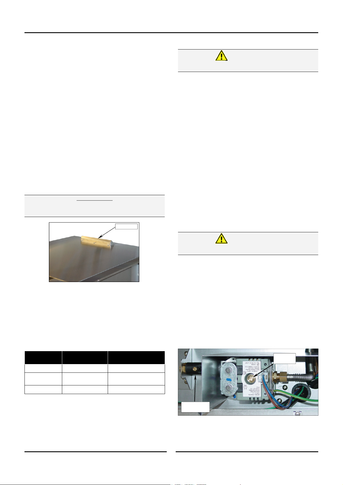
The appliance combination gas valve is fitted with an internal
regulator for adjusting the operating pressure. To access, remove
appropriately marked service panel from beneath the oven door.
Unscrew and remove regulator cap from the gas valve. Adjust the
regulator to achieve the stated pressure. Also refer to the
‘Specifications’ section.
NOTE: The Pressure Test Point is located behind the front
Pressure Test
service panel beneath the oven door.
Regulator
Cap
Point
11 May 2015
5
Amendment 10
Page 8

2 Installation
Water Connection - Optional
NOTE: If the Moisture Mode cooking option is not required,
1. Tighten 2 screws securing water
2. Connect a cold water supply to th
3.
Recommended Water Specifications
In order to prevent corrosion or scaling in the oven and water
system due to supplying water that is either too soft or too hard,
the following recommendations should be used as a guideline.
Positioning and Levelling of Oven
1. Correctly locate the oven into its final operating position and
the oven does not need to be connected to a water
supply.
nection to rear of oven. (The
con
urposely been left loos
have p
prev
ent damage to the wate
nection during transit).
con
w
ater inlet (R ¾” Connector) on th
oven.
- Max Inlet Pressure 80psi / 550kPa.
Turn ‘On’ the water supply and check for leak
Hardness: Between 60 and 90ppm.
PH: Greater than 7.5.
Chlorides: Less than 30 ppm.
using a spirit level, adjust the oven feet so that the oven is
level and at the correct height.
r
e to
se
e
e
Tighten Screws.
s.
Stand Mounted Ovens
For ovens that are to be mounted to a stand, the oven legs are
used to level the oven on the stand. Refer to the
instructions supplied with separately ordered stands for mounting
details.
Initial Start-Up
Before using the new oven;
1. For first time use of the oven, operate the oven for about 1
hour at 200°C/ 400°F to remove any fumes or odours whic
be present.
may
2.
Please refer to the Operation Section of this manual for detail
on how t
Commissioning
Before leaving the new installation;
Check the oven functions in accordance with the operating
instructions specified in the ‘Operation’ section of this manual.
o correctly operate and shutdown the ov
en.
h
Lighting the oven.
Turning ‘Off’ the oven.
Ensure that the operator has been instructed in the areas of
correct lighting, operation, and shutdown procedure for the
appliance.
s
NOTE: If for some reason it is not possible to get the
appliance to operate correctly, shut off the gas
supply and contact the supplier of this appliance.
11 May 2015
6
Amendment 10
Page 9
Operation Guide
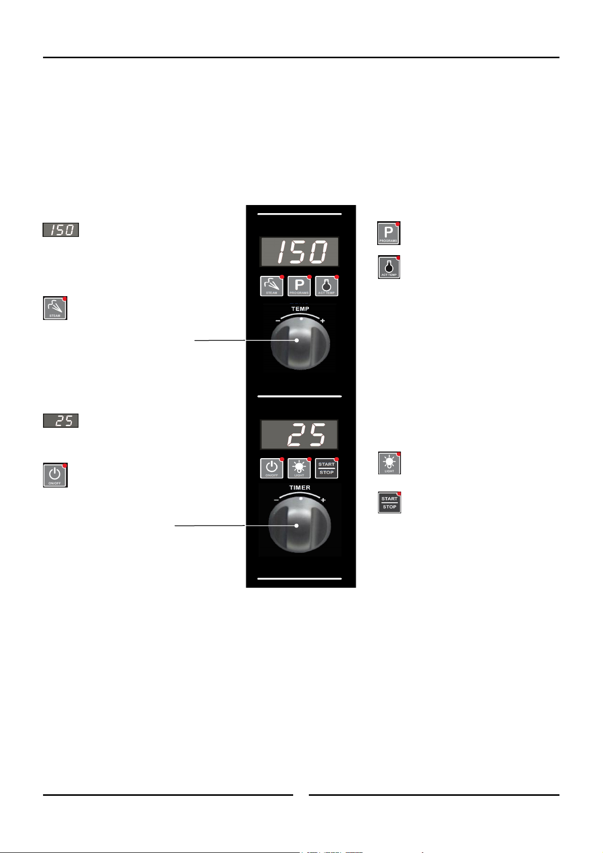
Oven Control Panel (Up to Ser. No. 762119)
Operation 3
Temperature Display - Shows
the preset chamber temperature.
When used with ‘Temperature’ button,
shows actual oven temperature for 5
seconds.
Shows Cooking Modes and Error Codes.
Steam Button and LED -
Activates the ‘Steam Mode’.
Temperature Adjustment Control.
Time Display - Shows cook
time in full minutes only from
180 - 1, and seconds for final
minute only.
On / Off / Stand-By Button and
LED - Press ‘On / Off’ button once
to turn the oven ‘On’.
Press and hold ‘On / Off’ button for
2 seconds to turn the oven ‘Off’.
Time Adjustment Control.
Programming Button and LED - Used
to enter the ‘Programming’ mode.
Temperature Button and LED - Shows
actual oven temperature for 5 seconds on
the Temperature Display.
LED ‘On’ when heating; LED flashes when
showing actual temperature.
Light On / Off Button and LED - Turns
oven light ‘On / Off’.
Start / Stop Button and LED - Pressing
the ‘Start / Stop’ button for 2 seconds,
when in the cooking cycle, will end the
cooking cycle.
11 May 2015
7
Amendment 10
Page 10
3 Operation
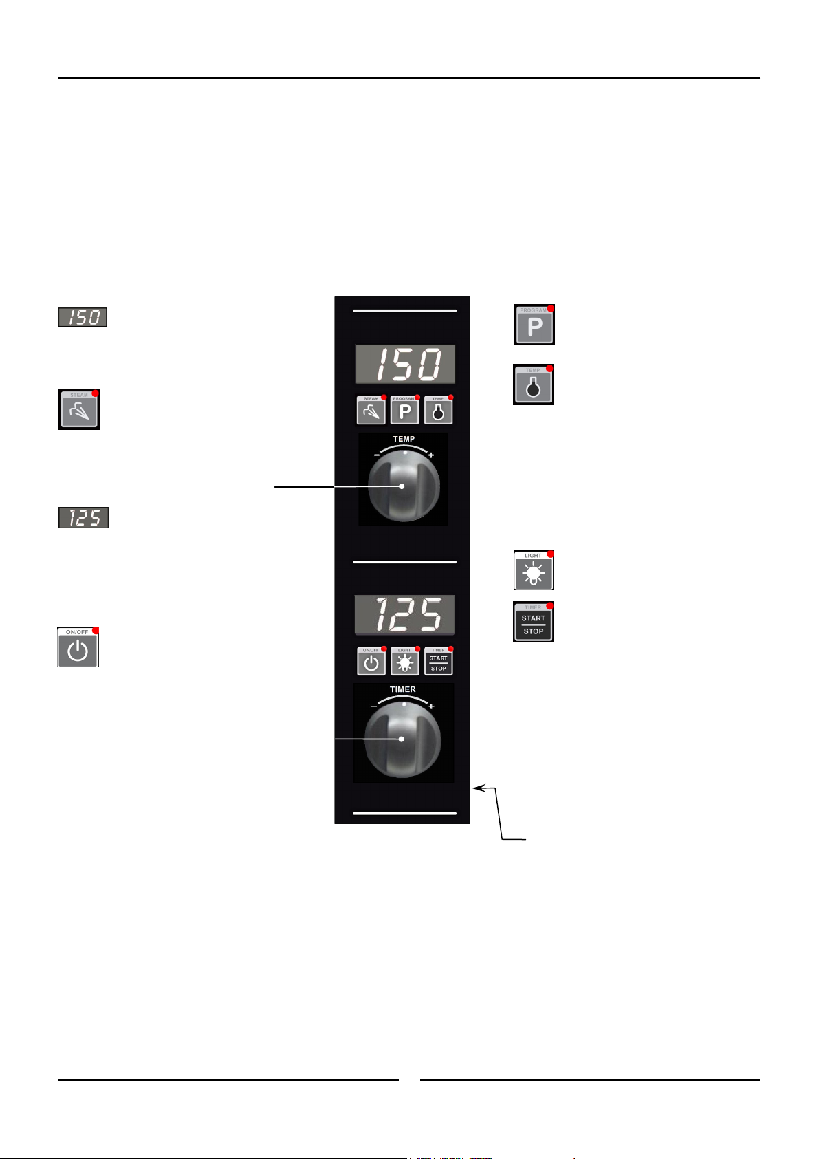
Oven Control Panel (From Ser. No. 762120)
Temperature Display -
Shows pre-set chamber temperature.
When used with the ‘Temp’ key, display shows
actual oven temperature for 5 seconds.
Shows cooking programs and error codes.
‘Steam’ Key and LED -
Used to set automated steam level or to
provide a manual steam injection when
in Manual Steam Mode.
LED is ‘On’ when automatic moisture injection is
set or when steam is manually injected.
Temperature Adjustment Control
Time Display -
Shows cook time in full minutes only
from 180 - 10, and in minutes and seconds for
the final 10 minutes.
NOTE:
In Core Temp Mode, time display alternates
between ‘CP’ and set core probe temperature.
‘On/Off’ Key and LED -
A dual-function key:
Press ‘On/Off’ key once to turn oven ‘On’.
Press and hold ‘On/Off’ key for
1.5 seconds to turn the oven ‘Off’.
Time Adjustment Control
NOTE: In Core Temp Mode, ‘Timer’ knob is
used to set core probe temperature.
‘Program’ Key and LED -
Used to select cooking programs, and to
set program parameters.
‘Temp’ Key and LED -
Displays actual oven temperature for
5 seconds on Temperature Display. LED
‘On’ when heating element is on
(heating indicator).
LED flashes when Upper Display is showing
actual temperature.
NOTE:
In Core Temp Mode, this key is used to
display Actual Oven Temperature (Upper
Display) and Core Probe Temperature (Lower
Display).
‘Light’ Key and LED -
Switches oven lights ‘On/Off’. LED is
‘On’ when oven lights are ‘On’.
‘Timer-Start/Stop’ Key & LED -
The ‘Timer-Start/Stop’ key is used to
control the following functions:-
Cancelling Alarm (All Modes).
Starting Core Temp Mode (Core Temp
Mode).
Starting Timer (Manual Mode).
Re-setting Timer (Manual Mode).
Starting Program (Program Mode).
Cancelling and Re-setting Program
(Pr
ogram Mode).
11 May 2015
Core Probe Connection Point
8
Amendment 10
Page 11
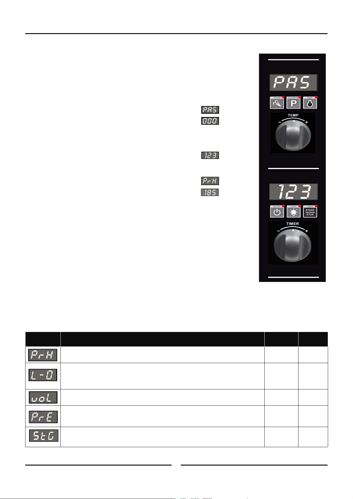
Changing Operator Settings
With the Oven in ‘Stand-By’ Mode (i.e. Power to oven but both displays blank).
1. ENTER OPERATOR PARAMETER MODE.
Press and hold 'Steam' and ‘Timer-Start/Stop’ keys together.
Operation 3
‘Upper’ Dis
‘Lower’ Display will flash ‘000’.
play will show ‘PAS’.
2. SETTING PASSWORD (Operator Password - 123).
otate ‘Timer Control’ to set password.
R
(123 - Operator Password)
Pres
s ‘Light’ key to confirm password.
‘Upper Display’ will show one of the Parameter Codes, eg.
‘Lower Display’ will show the parameter value.
3. SETTING THE PARAMETERS.
otate ‘Timer’ knob to the parameter required.
R
Press ‘Light’ key to confirm parameter required. ‘Lower Display’ will flash.
While ‘Lower Display’ is flashing, rotate ‘Timer’ knob to select value required.
Press ‘Light’ key to confirm value. ‘Lower Display’ will stop flashing.
4. EXITING THE PARAMETER MODE.
Pres
s ‘On/Off’ key, to return to Stand-By Mode.
Operator Settings
Setting
Number
Oven Pre-Heat; - (Automatic Pre-Heat Temp on oven start-up).
Light Auto ‘Off’ Setting Time -
0 = ‘On/Off’.
1 = 1 minute auto ‘Off’.
2 = 2 minutes auto ‘Off’, etc.
Alarm Volume - Can be adjusted to suit operators preference.
Program Pre-Heating Condition - This setting allows for pre-heating ‘Ready’ temperature in
‘Program Mode’ Mode to be set higher than Program Set Temperature. Factory Default Setting
is ‘0’ (Equal to Program Setting).
Multi-Stage Enable (From Ser. No. 762120 only).- This setting enables multi-stage
programming. Factory Default Setting is ‘YES’, multi-stage programming is enabled.
Changing this setting to ‘no’ simplifies programming and program cooking.
11 May 2015
Description
9
Setting
Range
60 - 260°C
140 - 500°F.
0 - 60 mins.
0 - 10.
0 - 30°C
0 - 54°F.
‘YES’ or ‘no’.
Default
Setting
150ºC
302ºF
0
5
0
YES
Amendment 10
Page 12

5 Parts Replacement
5.1 Replacement
5.1.1
5.1.2 Cooling
5.1.3
5.1.4
5.1.5
5.1.6 Ignition Module /
5.1.7 Door Microswitch /
5.1.8 Gas Valve /
Oven Controller /
Encoder
Tr
Capacitor
Overtemp Thermostat /
Temperature
O
O
F
B
Microsw
Gas Burner /
I
............................................................................................................................................. 11
Fan /
ansformer /
.......................................................................................................................................... 12
Probe ........................................................................................................................... 13
ven Lamp Assy ............................................................................................................................... 14
ven Fan /
an Motor ......................................................................................................................................... 15
urner Overtemp (Thermal Switch) ................................................................................................. 16
itch Return Spring ............................................................................................................... 16
gnition Electrode Assembly ............................................................................................................. 17
5.1.9 Door Inner Glass /
5.1.10 Water Solenoid ................................................................................................................................. 19
Door /
Door
Hinges ...................................................................................................................................... 18
5.2 Adjustment & Calibration
5.2.1 Door Alignment
5.2.2 Door Catch / Latch Adjustment ........................................................................................................ 20
5.2.3
5.2.4
Microswitch .............................................................................................................................. 21
Door
T
emperature Calibration .................................................................................................................. 21
................................................................................................................................ 20
11 May 2015
10
Amendment 10
Page 13
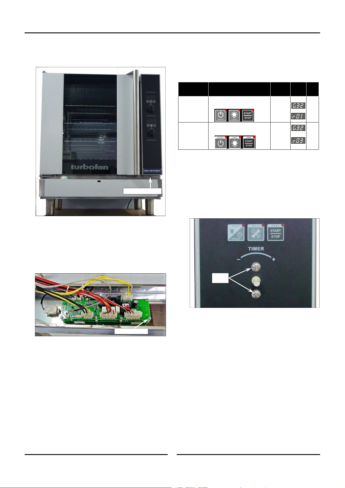
5.1 Replacement
Parts Replacement 5
5.1.1 Oven Controller /
Encoder
Control Panel Screw
To Program the New Oven Controller
1. Check / adjust Parameters P01, P02 and P24 to the model
specific values shown belo
Model /
Revision
G32D
Rev 01
G32D
Rev 03
Encoder
1. With control panel removed from the oven, remove control
knob
from control panel.
2. Disconnect encoder plug from digital control board.
3. Remove oven controller if necessary.
4. Remove encoder from control panel by removing 2 securi
screws.
Key Identifiers PO1 PO2 P24
No Light Key.
Fan LO Key.
Square Lights in Oven.
Keys - New style graphics
w.
°C / °F
as reqd.
°C / °F
as reqd.
N/A
N/A
ng
To remo
1.
Remove screw on underside of control panel.
2.
Lift panel up to unhook at top.
Disconnect plugs from rear of control panel.
3.
ve the Digital Control Board:-
Note position of connectors before disconnecting plugs
from con
Disconnect earth connection at rear of control panel.
4.
5.
Undo the shake-proof securing nuts (8).
6. Remove digital control board from rear of control panel.
To replace the Digital
1
. Ensure 8 spacers are fitted to threaded studs on rear of contro
bo
2. Fit replacement digital control board to threaded studs
sec
3.
Re-connect plugs to control board, noting position
con
trol board.
Securing Nuts (8)
Control Board:-
ard before fitting new board.
and
ure with nuts supplied and tighten nuts hand tight.
of
nectors when re-fitting.
Securing
Screws
l
11 May 2015
11
Amendment 10
Page 14
5 Parts Replacement
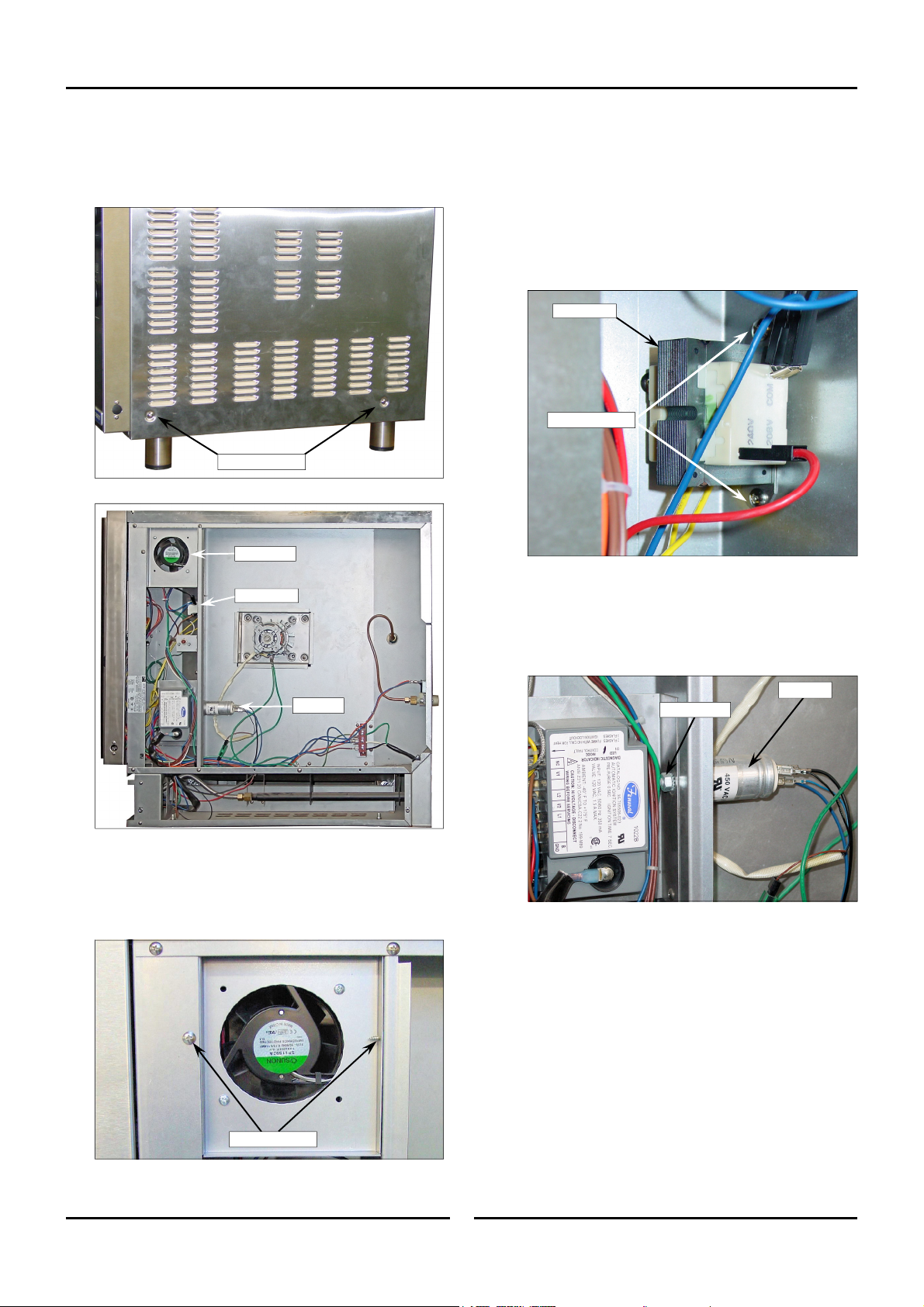
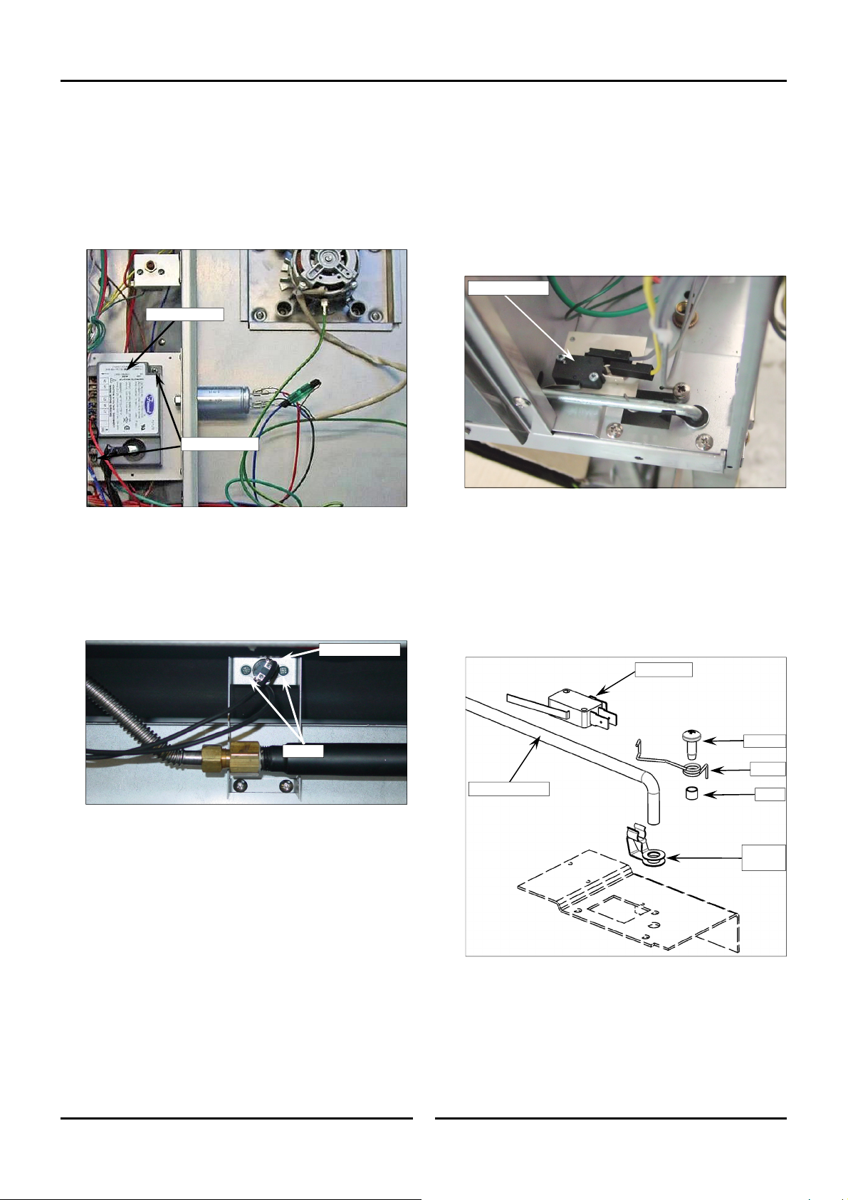
5.1.2 Cooling Fan / Transformer / Capacitor
1. Remove 2 screws on lower corners of side panel.
Pull bottom of panel out and away from bottom of oven.
2.
3. Pull down on panel to remove side panel.
Securing Screws
Cooling Fan
Transformer
Transformer
Disconnect electrical connections from transformer.
1.
2. Remove 2 screws securing transformer to oven chassis.
Transformer Specifications;
Primary; 200 - 208V / 220 - 240V.
Primary; 110 - 120V.
Secondary;
Transformer
Securing Screws
3.
Replace transformer and refit in reverse
12Vac.
order.
Capacitor
1.
Remove wires from rear of capacitor.
2. Remove capacitor securing nut.
Capacitor
Cooling Fan
Remove 2 screws securing cooling fan bracket.
1.
2. Rotate LH side inwards to remove fan assembly. Remove
ling fan from bracket.
coo
Securing Screws
Securing Nut
3. Replace capacitor(s) and refit in reverse or
3uF
s;
(208 - 240V).
Capacitor Specification
Motor Capacitor,
M
otor Capacitor, 12uF (110-120V).
Capacitor
der.
Replace in reverse order.
3.
11 May 2015
12
Amendment 10
Page 15
Parts Replacement 5
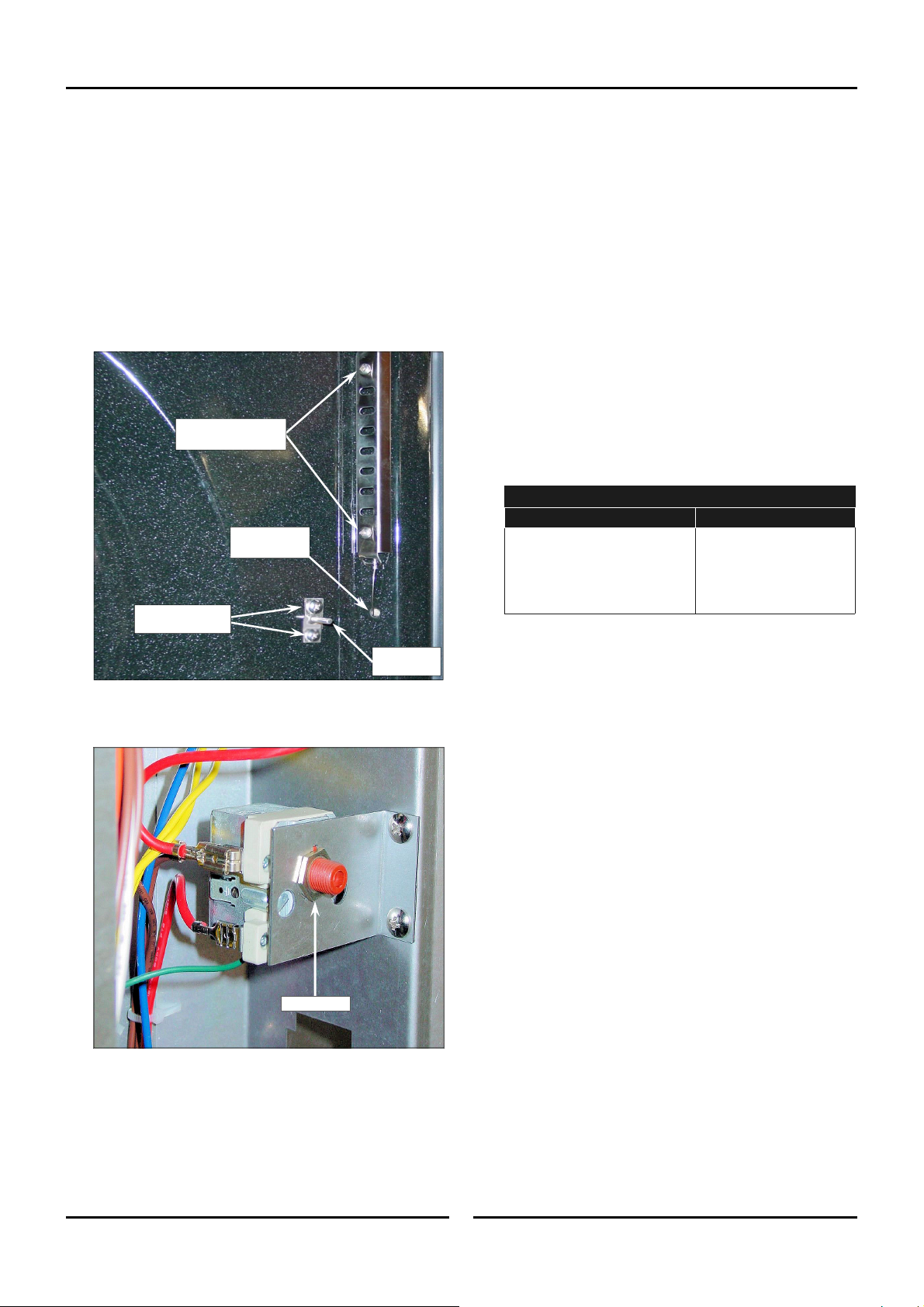
5.1.3 Overtemp Thermostat /
Temperature Probe
1. Remove RH louvered side panel.
2. Inside oven remove side oven rack
Overtemp Th
1.
From inside the oven, remove overtemp phial ho
ermostat
.
lder (two
screws).
Withdraw phial through oven cavity
2.
Remove wires from overtemp thermostat, noting positions.
3.
4.
Remove mounting nut securing overtemp to mounting bracke
and remove th
e overtemp.
Overtemp Phial Holder
Securing Screws
Seal hole with
RTV Silicone
Temperature Probe
Securing Screws
.
Temperature
1. Remove
connect temperature probe cable from controller.
2. Dis
Probe
control panel.
3. From inside oven, remove RH side oven rack.
4. Undo temperature probe securing screw(s).
t
5. Withdraw probe and cable through oven cavity
6.
Clean off any existing silicone from around the te
p
robe opening in the oven inner wall.
7. Fit the new gasket to the rear of the new temperature prob
and f
eed the probe cable through oven cavity
8.
Connect temperature probe cable to oven controller
9.
Secure temperature probe to oven using the supplied screws
1
0. Refit the control panel.
Carry out a functional check of temperature probe using th
11.
oven con
troller.
.
mperature
e
.
.
.
e
Temperature Probe Type PT1000
Temperature oC (oF) Resistance ± 5%
0 (30) 1000 Ω
50 (122) 1194 Ω
100 (212) 1385 Ω
150 (302) 1573 Ω
180 (356) 1685 Ω
Temperature
Probe
5. When replacing the overtemp use RTV silicone sealant to seal
the hole in the oven liner.
Mounting Nut
6. Refit overtemp in reverse order.
11 May 2015
13
Amendment 10
Page 16
5 Parts Replacement
5.1.4 Oven Lamp Assy
Oven Lamps (Up to Ser. No. 762119)
1. Remove the oven rack and LH side rack fr
2.
Unscrew and remove the lamp glass (anti-clockwise) from
oven.
3
. Remove the light bulb which is a push fit into the light hold
4.
ace if requir
and repl
Remove seal fitted between lamp glass and holder and replac
uired
if req
.
ed.
om oven.
the
er
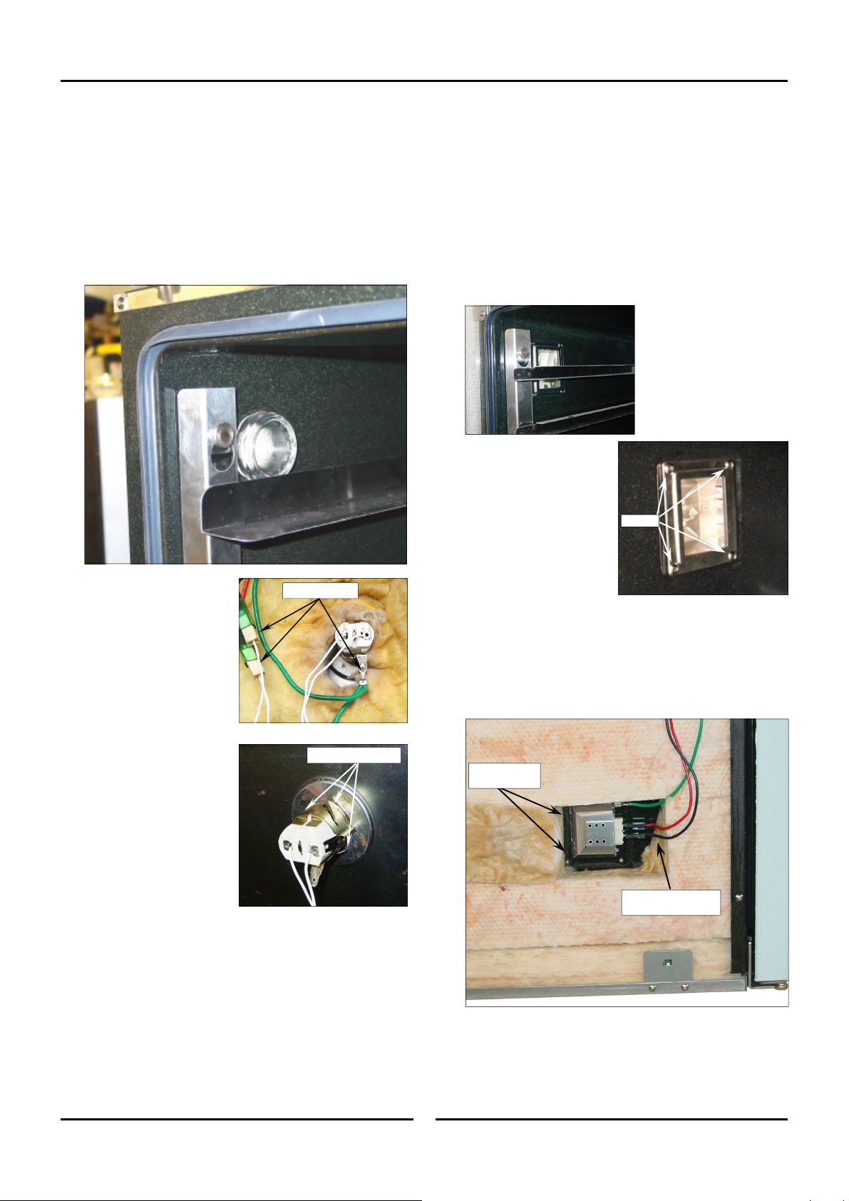
Oven Lamps (From Ser. No. 762120)
Oven Lamp / Oven Lamp Glass / Oven Lamp Seal /
Oven Lamp Housing
1. Remove LH side rack from ov
. Remove 4 screws securing the lamp support frame.
e
2
3. Remove support frame, glass lens and gasket
. Remove light bulb if required (this is a push fit into housing).
4
en.
.
Screws
Remove th
5.
panel
6. Disco
connections to the oven lamp
assy being replaced.
7. Pull back the insulation
reveal the rear of the lamp
assembly.
8.
Depress the 3 spri
load
rear of the light assy and
p
ush the assembly into
oven and
9. Refit oven light
reverse order.
1
0. Ensure the insulation
re-pos
of t
1
1. Refit the LH side rack and
oven rack to the oven.
12. Refit the LH oven side panel.
e LH Oven side
.
nnect the electrical
ed locking tabs
remove.
itio
ned around the rear
he lamp assembly
ng
assy in
to
on the
the
is
.
Disconnect
Securing Tabs (3)
To replace Oven Lamp Housing:
1.
Remove oven non louvered side panel.
2. Pull back insulation to reveal rear of lamp assy
Disconnect electrical connections on rear of lamp assy.
3.
4. Depress spring loaded locking tabs on rear of light assembly
and push assembly into oven and remove.
Depress Spring
Tabs
Disconnect Electrical
Connections (3)
.
11 May 2015
14
5.
Refit oven lamp assembly in reve
rse order.
Amendment 10
Page 17
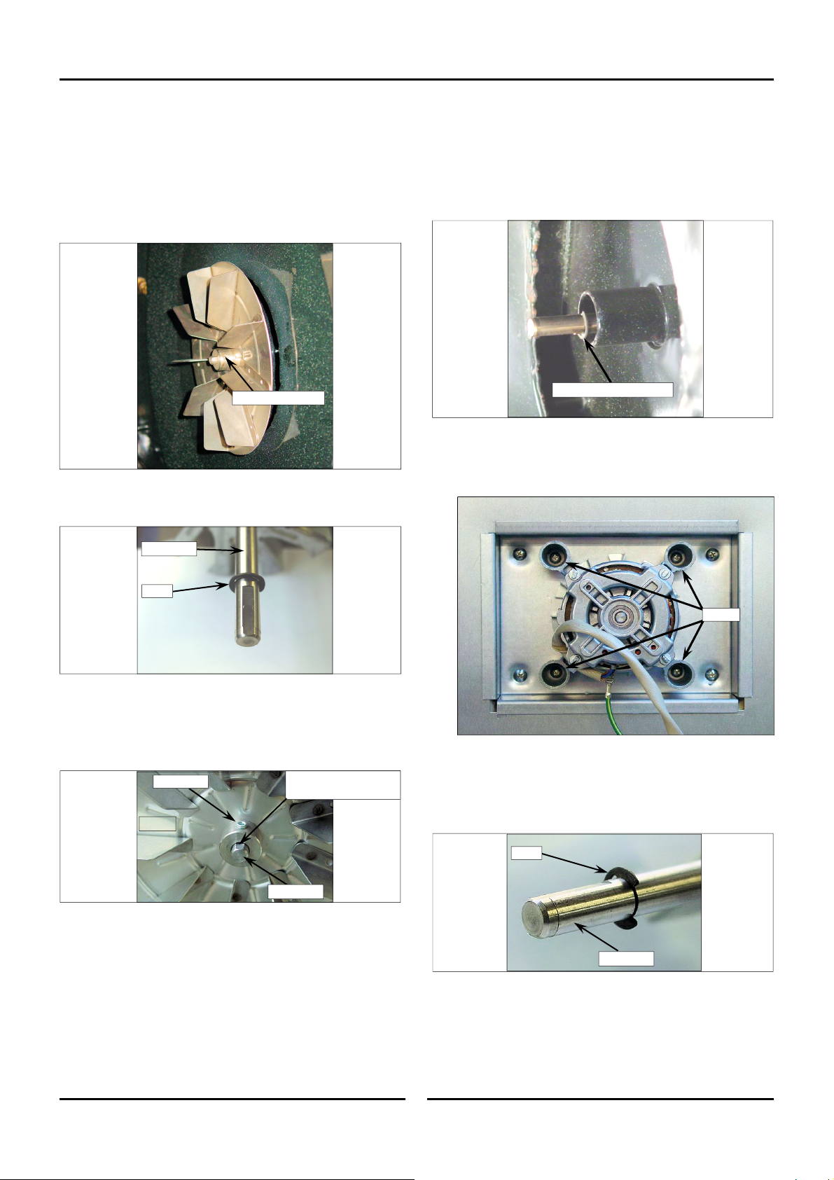
5.1.5 Oven Fan / Fan Motor
1. Remove RH louvered side panel.
Parts Replacement 5
Oven Fan
Inside oven remove RH Side oven rack
1.
2.
Remove the 2.5mm grub screw securing the oven
an motor shaf
f
3.
Remove the oven fan from inside the oven.
t.
.
fan to the
2.5mm Grub Screw
NOTE: Ensure the E-Clip is still fitted to the motor shaft
before replacing the oven fan.
Motor Shaft
Fan Motor
1.
Remove the oven fan as shown opposite.
2. Remove and retain the E-Clip fitted to the motor shaft.
Remove and Retain E-Clip
3. Disconnect motor wires from motor connection block, no
wire p
Remove Motor mounting screws and remove the motor
4.
osition
s.
the oven.
te
from
E-Clip
3. Refit oven fan, pushing fan back against the E-Clip
4
. Rotate the fan until the fan securing grub screw is located
.
over the flat of the motor shaft.
5. Securely tighten the grub screw onto the ‘D’ section of th
m
otor shaft to secure the fan to motor shaft.
Grub Screw
Fan
Note Flat on Motor Shaft
for Grub Screw location.
Motor Shaft
Screws
e
5.
Replace motor and secure with 4 screws
. Reconnect motor wires to connection block, note wi
6
po
sitions.
From inside the oven refit the E-Clip into the groo
7.
m
otor shaf
. Refit oven fan as shown opposite.
8
t.
E-Clip
Motor Shaft
.
re
ve on the
9. Refit RH oven side panel.
11 May 2015
15
Amendment 10
Page 18
5 Parts Replacement
5.1.6 Ignition Module /
Burner Overtemp (Thermal Switch)
1. Remove RH louvered side panel.
Ignition Module
1.
Disconnect plug connections from Ignition Module.
2. Remove and replace Ignition Module
Re-connect the plug connections to the Ignition Module.
3.
Ignition Module
Securing Screws
.
Burner Overtemp (Thermal Switch)
Remove RH side panel.
1.
2.
Remove wires from burner overtemp
Remove securing screws and replace burner overtemp.
3.
.
4. Refit replacement burner overtemp and connect up wi
temp
over
.
Burner Overtemp
res to
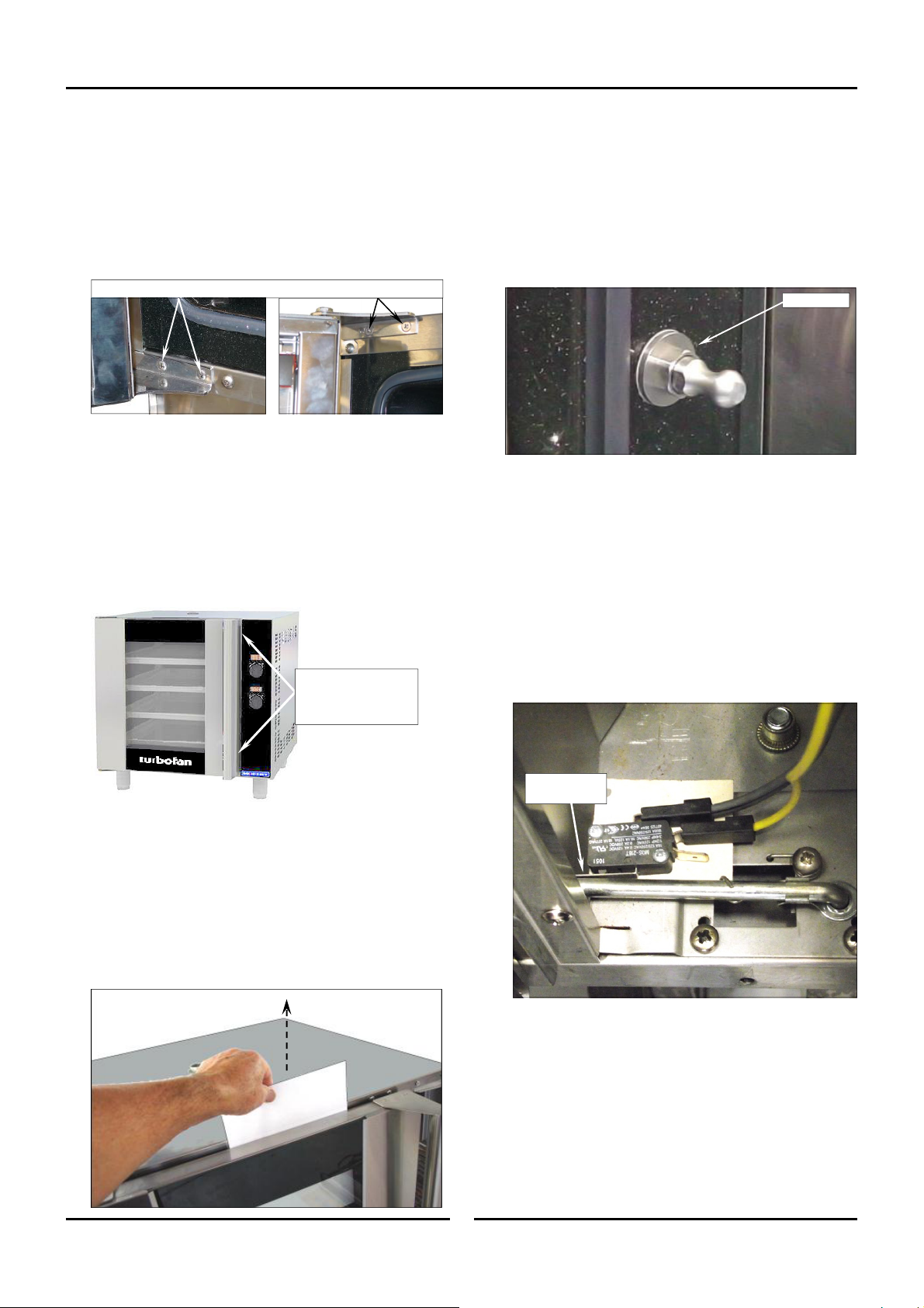
5.1.7 Door Microswitch /
Microswitch Return Spring.
To replace Door Microswitch:
1. Remove
control panel.
2. Remove oven RH side panel.
3. Remove electrical connections from door microswitch.
4. Remove
Check adjustment when new door microswitch is fitted. Refe
5.
Sec
microswitc
h.
tion 5.2. ‘Adjustment & Calibration’.
Door Microswitch
To replace Door Microswitch Return Spring:
croswitc
croswitc
control panel.
curing screw and spacer from
h bracket.
rod and
h bracket.
e order.
Microswitch
1. Remove
2.
Unscrew and remove spring se
mi
3.
Unclip and remove return spring from microswitch
mi
Refit replacement spring in revers
4.
r
5.
Refit RH side and Gas Control panels
11 May 2015
.
Screws
16
Microswitch Rod
Screw
Spring
Spacer
Retaining
Clip
Amendment 10
Page 19
Parts Replacement 5
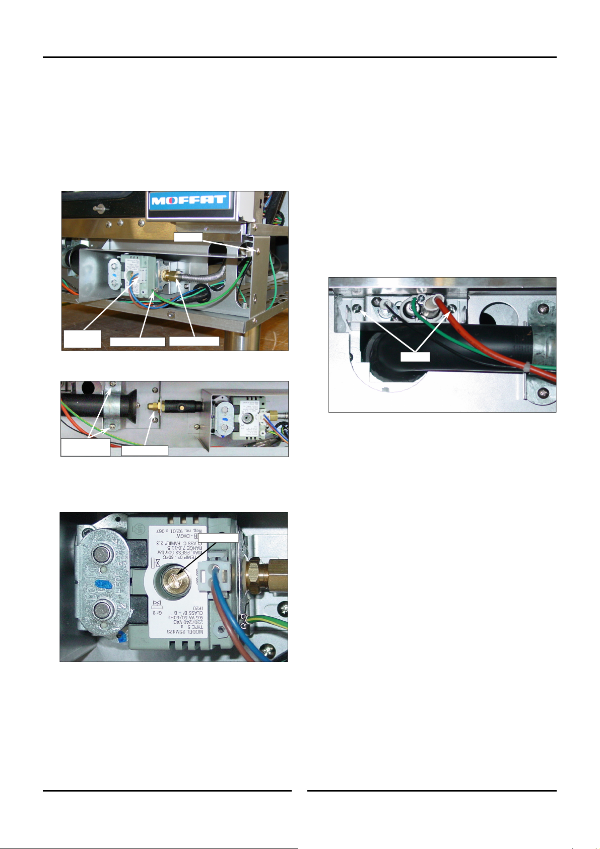
5.1.8 Gas Valve / Ignition Electrode
Assembly / Gas Burner
1. Remove gas control panel.
Gas Valve &
1. Remove gas control
Remove cover bracket, 1 screw.
2.
Remove earth and power connectors.
3.
4. Disconnect gas inlet pipe to Gas Valv
Power
Connector
. Remove injector and securing nut.
5
Burner Injector
panel.
Earth Connector
e.
Screw
Gas Inlet Pipe
Ignition Electrode Assembly
1. Remove burner access panel.
2. Disconnect wires from the Ignition Electrode Assembly to th
Ignition Module.
3
. Remove 2 slotted screws securing Ignition Electrode Assemb
he oven
to t
Withdraw the ignition electrode assembly and replac
4.
Before fitting the new ignition electrode assembly,
5.
spark ele
2 ‘Adjustment and Calibratio
5.
Re-connect wires from the new Ignition Electrode Assembly
6.
the I
.
ctrode / flame sensor gaps are as shown
n’.
gnition Module.
Screws
e.
check the
in Section
e
ly
to
Burner Bracket
Screws
6.
Remove securing screws and remove gas valve with bracket.
7. Replace and refit in reverse or
8.
Remove screw cap and fit correct spring for the gas type bein
Injector & Nut
der.
used.
Screw Cap
. Adjust operating pressure as shown in Section 9. ‘G
9
Conversion and Specifications’ section.
Gas Burner
Remove Ignition Electrode Assembly as sh
1.
Remove burner bracket screws (2).
2.
3. Carefully withdraw
Fit replacement
g
4.
burner.
burner and refit in reverse order.
own above.
as
11 May 2015
17
Amendment 10
Page 20
5 Parts Replacement
5.1.9 Door Inner Glass / Door / Door Hinges
To replace Door Inner Glass:
1. Undo inner glass retaining clip.
Retaining Clip
2. Lift inner glass up and pull bottom outwards to free bottom
pivot.
NOTE: Pivot spacer is a loose fit over pivot and may fall
out.
3. Lower inner glass to free top pivot and remove glass.
To replace Door Hinges:
1. Remove door and inner glass complete. (as shown previous
2.
Remove 2 Hinge Plate Screws
Remove the upper and lower hinge plates
3.
Refit replacement door hinge plates.
4.
5. Refit door and inner glas
: The Door Hinge Assembly can be ordered as a
NOTE
.
.
s.
Remove Top or Bottom
Hinge Plate Screws.
complete Door Hinge Replacement Kit or as
separate items as shown below.
Door Top Hinge Assemby.
Door Hinge Pivot Pin.
Nord-Lock Washer.
Door Hinge Pivot Bush.
Door Bottom Hinge Assemby.
).
Pivot Spacer
4. Replace and refit door inner glas
to ref
it Pivot Spacer to bottom hing
s in reverse order, remember
e.
To replace Door:
1. Remove door inner glass (as above).
2. Whilst supporting door, unscrew and remove top door hi
pi
vot bolt from the door top hinge assembly
3.
Remove the Nord-Lock Washer.
4.
Lift door off the bottom hinge.
.
Remove Door Top Pivot Bolt.
Nord-Lock Washer.
Pivot Bush
nge
Door Hinge Pivot Bush.
Nord-Lock Washer.
Door Hinge Pivot Pin.
To replace Door Hinge Pivot Bushes:
Remove door complete
1.
2.
Unscrew and remove top and bottom plates from the door
3.
Tap out the old Door Hinge Pivot Bushes and discard.
4. Gently Tap in the new pivot bushes
. Refit the oven door as shown opposite.
5
.
Unscrew 2 Screws
Door Hinge Pivot Bush.
.
.
5.
Refit door in reve
11 May 2015
rse order.
18
Amendment 10
Page 21
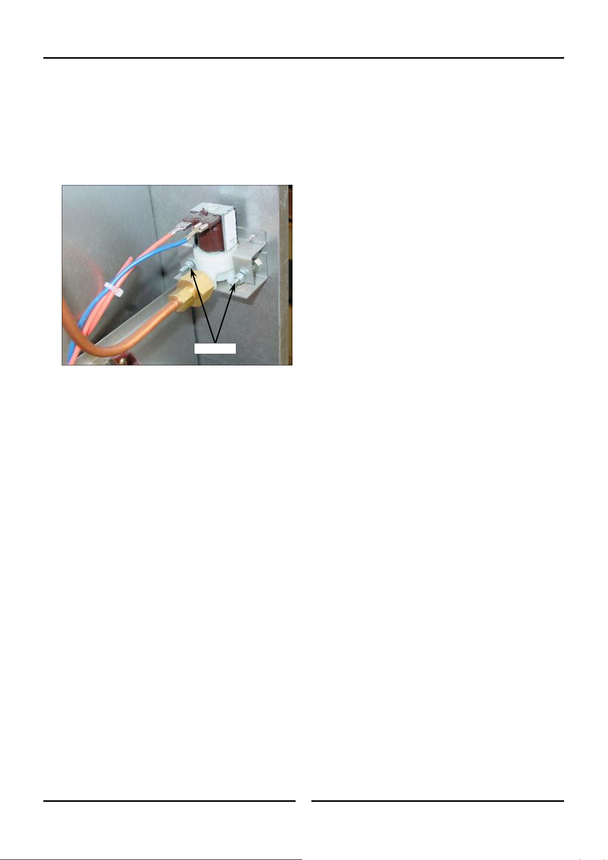
5.1.10 Water Solenoid.
1. Remove control panel.
2. Remove oven RH side panel.
3.
Turn Off wa
Remove wires from water sole
4.
Disconnect water pipes.
5.
6. Remove Nylock nuts (7mm) and mounting screws
7
. Remove water solenoid.
ter.
noid.
Parts Replacement 5
.
8.
Replace water soleno
Nylock Nuts
id and refit in reverse order.
11 May 2015
19
Amendment 10
Page 22
5 Parts Replacement
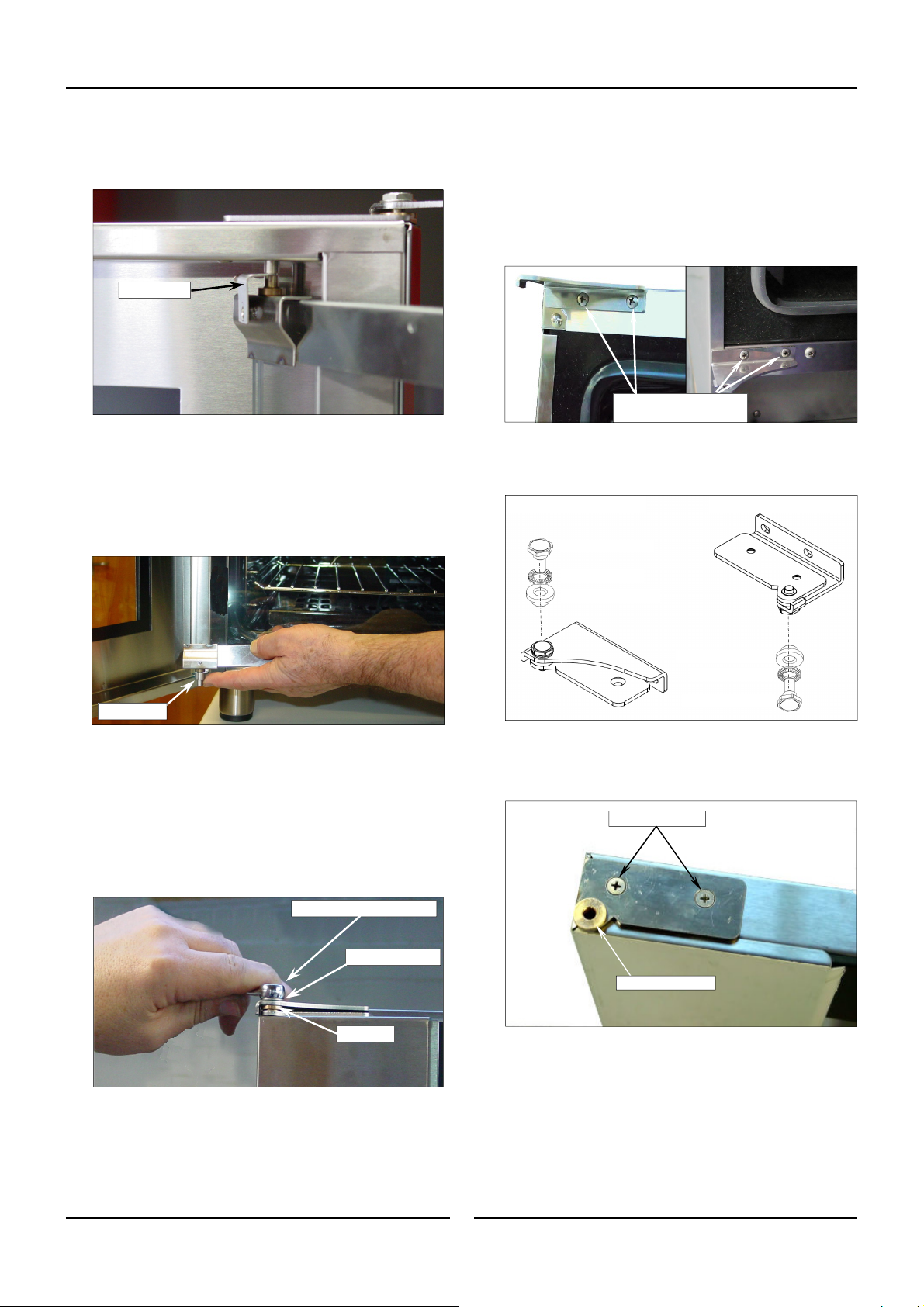
5.2 Adjustment & Calibration
5.2.1 Door Alignment.
Ensuring Door is Square to Oven.
Check alignment and operation of the door. Ensure that the door
is correctly aligned horizontally and vertically.
There should be a
nominal gap of 6mm from edge of door to side of control
panel.
Slacken these screws to adjust door vertically - horizontally.
1. Slacken off the upper and lower hinge plates and correctly
align the door. Re-tighten both hinge plates on completion.
NOTE:
Check the nominal gap from front edge of door to side
of control panel. This should be 6mm.
If door is adjusted for correct alignment, ensure that
the door closes correctly. Check door closes correctly
as shown below at Section 5.2.2 ‘Door Catch / Latch
Adjustment’.
Check Gap between Door
and Control Panel at top
and bottom of Door.
Should be 6mm nom.
3. To adjust door catch, loosen the locking nut on the door catch.
4. If paper withdraws easily,
turn
and repeat test above until adjusted correctly.
5. If paper cannot be withdrawn and door springs open,
door catch ‘Out’ by ½ a turn
il adjusted correctly.
unt
6.
Tighten the locking nut on the door catch.
Ensuring Door Latches Closed Properly:
1. Check that the door closes and latches correctly by push
the door clo
ithout springing open.
w
2. If the door is hard to close and springs open,
sed and ensuring that the door remains clos
catch ‘Out’ by ½ a turn
adjusted corre
If the door closes and feels loose once latched closed,
3.
ctly.
door catch ‘In’ by ½ a turn
oor is adjusted correctly.
d
4.
Tighten the locking nut on the door catch.
5.2.3 Door Microswitch
screw door catch ‘In’ by ½ a
screw
and repeat the test above
Locking Nut
ing
ed
screw door
and repeat test above until door is
screw
and repeat the test above until
5.2.2 Door Catch / Latch Adjustment.
Ensuring Door Seals Properly:
If the door sealing requires adjustment, carry out the following to
adjust the door catch:-
1. Check that the door seals correctly when closed, by plac
s
heet of paper between the door and the seal
. Close the door on the paper and attempt to withdraw
2
paper by
pull out with some resistance but without tearing.
11 May 2015
firmly tugging on the paper. The paper should just
.
ing a
the
Microswitch
Activation Arm
1. Remove control panel.
Bend the microswitch activation arm so switch open circuits
2.
when door is open.
Check adjustment when door is opened and closed
3.
20
.
Amendment 10
Page 23

5.2.4 Temperature Calibration
1. Place temperature probe in the centre of the oven.
2. Close the door and allow temperature to stabilise.
3. Enter service parameters settings menu on control panel
che
ck P10 Temperature Offset (refer to Sectio
ing / Changing Service Para
‘View
meters’).
n 6.
5.2.5 Spark Electrode Adjustment.
The recommended gap settings for the ignition electrodes are
given in the diagram below.
‘a’ 18.3mm (+0.5mm, -0mm).
3
/4” (+1/64”, -0”).
‘b’ 4.5mm (+0.5mm, -0mm).
3
/16” (+1/64”, -0”).
FLAME SENSER
EARTH / GROUND
Parts Replacement 5
and
‘a’
‘b’
SPARK
11 May 2015
21
Amendment 10
Page 24

6 Controller Programming
6.1 Viewing / Changing Service Parameters
With the Oven in ‘Stand-By’ Mode (i.e. Power to oven but both displays blank).
1. ENTER SERVICE PARAMETER MODE.
Press and hold 'Steam' and ‘T
‘Upper’ Display will show ‘PAS’.
The ‘Lower’ Display will flash.
imer-Start/Stop’ keys together for 3 seconds.
2. SET PASSWORD (Service / Factory Password - 321).
Rotate ‘Timer Control’ to set password;
321 - Service Password).
(
Press ‘Light’ key to confirm password.
‘Upper’ Display will show one of the Parameter Codes.
‘Lower’ Display will show the parameter value.
3. SETTING THE PARAMETERS.
Rotate ‘T
Pres
imer’ Knob to the parameter required.
s ‘Light’ key to confirm parameter. ‘Lower Display’ will flash.
While ‘Lower Display’ is flashing, rotate ‘Timer’ Knob to select value required.
Press ‘Light’ key to confirm value. ‘Lower Display’ will stop flashing.
4. EXITING THE PARAMETER MODE.
Press ‘T
imer-Start/Stop’ to, to return to ‘Stand-By’ mode.
11 May 2015
22
Amendment 10
Page 25

Controller Programming 6
6.2 Viewing / Changing Service Parameters (up to Ser. No. 762119)
Parameter
Number
P1 Temperature Scale
Description Min Max Default Value S / O
˚F ˚C
˚C
---- S
P2 Oven Model. 31 32 32 ---- S
P3 Minimum Temperature Setpoint. 0(32) 300(572) 60(140) ˚C(˚F) S
P4 NOT SHOWN WHEN P2 SET TO 32
Maximum Temperature Setpoint
P5
PrH NOT SHOWN WHEN P2 SET TO 32.
H Temperature preset.
Pr
P3 P5 150(325) ˚C(˚F) O
0(32) 300(572) 260(500) ˚C(˚F) S
P8 Hysteresis Temperature Gap. 1 10 1 ˚
P9
Temperature Regulation Offset. 0 10 0 ˚
Chamber Temperature Offset.
P
10
(This offset is always added to the raw temperature measurement,
in order to correct the value. The value shown on display is the
-25(-45) 25(45) 0(0) ˚C(˚F) S
corrected value).
P11 Maximum Timer Setpoint. 1 180 180 Min S
P12 Timer Preset. 1 P11 0 Min S
L-O Time Light stays on. 0 60 0 Min O
InJ Steam Injection Time
0 10 0 Sec O
P15 Cooling Fan Timeout. 0 60 10 Min S
P16 Oven Fan Rotation Time
P17 Oven Fan Inversion Pause Time
1 999 120 Sec S
5 10 10 Sec S
VoL Buzzer Volume 0 10 5 ---- O
P19 NOT SHOWN WHEN P2 SET TO 32
20 Thermal switch NO or NC contacts 0 1 1 ---- S
P
P21 Program Mode - Pre-heat temp condition. 0(0) 30(54) 20(36) ˚C(˚F) O
P22 Door open time—Program Mode Only. 30 180 60 Sec S
S
S
1) To change the parameter turn the timer encoder knob.
2
) To enter the parameter, to change it’s value, press the light button.
3)
To change the value turn the timer encoder knob
) To enter the value press the light button.
4
5)
Press ‘On / Off’ button to exit.
.
11 May 2015
23
Amendment 10
Page 26

6 Controller Programming
6.3 Viewing / Changing Service Parameters (from Ser. No. 762120)
: All units produced after this point are G32r03 Units, but older units can fit the new controller as a spares item, in which
NOTE
case Parameter Number ‘P02’ is set to ’G32r01’.
Parameter
Number
P01
P02
P03
P04
P05
P06
PrH
P08
P09
P10
P11
P12
L-O
P13
P14
InJ
P15
Description Min Max
Temperature Scale.
Defines temperature scale used
(C = °C, F = °F). Changing scale from °F to °C will reset all
temperature parameters to their default values.
Oven Model and Software Revision.
Minimum Oven Temp Set Point.
The minimum temperature
that the oven can be set to.
Maximum Oven Temp Set Point.
The maximum temperature
that the oven can be set to.
Minimum Core Temp Set Point.
The minimum core
temperature that can be set.
Maximum Core Temp Set Point.
The maximum core
temperature that can be set.
Oven Default Preheat Temp.
The temperature that the oven
will pre heat to on start-up.
Hysteresis Temperature Gap.
The temperature drop from
the Set Point before the heating cycles back ‘On’.
Temperature Regulation Offset.
The temperature below set
point that the oven heating turns off. i.e. If P9 is set to 5 and
oven temperature is set to 180, oven heating will turn ‘Off’ at
175. This is intended to allow for thermal over-run in the oven
cavity
.
Oven Temperature Offset.
This offset is always added to the
raw temperature measurement, to correct the value. Value
shown on display is the corrected value).
Maximum Timer Set Point.
Core Temp Verification Time.
Maximum time that can be set.
Time required for Core Probe
to be at or above the Set Temperature before the cooking done
alarm sounds.
Time Light stays On.
Duration of time for which light stays
‘On’. Pressing ‘Act Temp/Light Key will turn oven light ‘On / Off’
in all settings. If 1-60min set, oven light will turn off after set
time elapsed. If ‘0’ is set, key must be pressed to turn lights ‘Off’.
Steam Cycle Time.
The time duration in minutes for each
steam cycle.
Steam Injection Pulse Time.
The time duration in seconds
for each steam pulse within the steam cycle (P13).
Note;- The number of steam injections per cycle is
determined by the humidity level set by the user, e.g. H1
= 1 Injection Pulse of (P14) seconds every (P13)
minutes.
Steam Injection Time (sec).
Cooling Fan Timeout.
The time that the cooling fan will
continue running after the ‘On/Off’ key has been pressed.
Default
G32R01 G32R03
˚C ˚F ˚C
E31 r01 G32 r03
0 (32) 300 (572) 60 (140) ˚C (˚F) S
0 (32) 300 (572) 260 (500) ˚C (˚F) S
0 (32) 150 (302) N/A 50 (122) ˚C (˚F) S
0 (32) 150 (302) N/A 90 (194) ˚C (˚F) S
P3 P4 150 (300) N/A ˚C (˚F) U
1 (2) 10 (18) 1 (2) °C / °F S
0 (0) 10 (18)
-25 (-45) 25 (45) 0 (0) 0 (0) ˚C (˚F) S
1 180 180 180 min S
1 120
0
1 5
0 5
0 10 0 N/A sec U
0 60 min S
G32r01 --- S
0
N/A 30
60 0 0 min U
N/A
N/A
10
˚C
G32r03
60 (140)
260 (500)
1 (2)
U o M
Pass
--- S
0
°C / °F S
sec S
2 min S
1 sec S
10
0
(0) Defines the password level of the parameter (S = Service / Factory. Password level 321)
User. Password level 123)
(U =
24
11 May 2015
.
Amendment 10
Page 27

Controller Programming 6
Viewing / Changing Service Parameters (from Ser. No. 762120) (Cont.d)
Parameter
Number
P16
P17
voL
P20
PrE
P22
P25
StG
Description Min Max
Oven Fan Rotation Time.
The time the fan will rotate in one
direction before changing direction.
Oven Fan Reversing Pause Time.
The time between the fan
stopping and re-starting in the opposite direction.
Buzzer Volume.
Volume of buzzer can be adjusted between ‘
O’ - No Buzzer and ‘10’ - Maximum Volume.
Thermal switch NO or NC contacts
Program Preheating Offset.
In Program Mode only. The
temperature above ‘Set Temperature’ that the oven will pre-heat
to. (To allow for heat loss during door opening and cold product
loading
). Note;- Upon starting the Program, Oven Set
Temperature will revert to the Set Temperature.
Maximum Door Open Time - Program Mode Only.
This is the time allowance for door open when loading oven, to
avoid Pre-Heating state re-activating once the door is closed.
Note: If door has been open longer than the time set (60)
and actual temperature has dropped below the set
temperature for that program, when the door is closed, the
oven will revert to the Pre-heating Mode.
Core Probe Temperature Offset.
This offset is always added to
the raw temperature measurement, to correct displayed value.
(Value shown on display is the corrected value).
Enable Multi-Stage Cooking.
This new parameter will control
whether or not the oven can program with multiple stages. Setting
defaults to ‘No’ ensuring programming for single stage ios as in
previous revision (No decimal numbers e.g. 1.1, 1.2 to indicate
stages).
Default
G32R01 G32R03
1 999 120 120 sec S
5 10 10 10 sec S
0 10 5 5 --- U
0 1 1
0 (0) 30 (54) 20 (36) 0 ˚C (˚F) U
30 180
25 (-45) 25 (45) N/A 0 ˚C (˚F) S
no YES N/A YES ---- U
60 60
1
U of M
--- S
sec S
Pass
0
P26
(0) Defines the password level of the parameter (S = Service / Factory Password level 321)
Maximum number of stages.
User Password level 123)
(U =
2 5 N/A 3 —- S
.
11 May 2015
25
Amendment 10
Page 28

7 Electrical Schematics
Circuit Schematic G32D Turbofan Oven, 220 - 240V.
Circuit Schematic G32D Turbofan Oven, 110 - 120V
11 May 2015
26
Amendment 10
Page 29

Wiring Diagrams 8
Wiring Diagram G32D4 Turbofan Oven, 220 - 240V
Round Lamps (Up to Ser. No. 762119)
Square Lamps (From Ser. No. 762120)
11 May 2015
27
Amendment 10
Page 30

Wiring Diagram G32D5 Turbofan Oven, 110 - 120V
Round Lamps (Up to Ser. No. 762119)
Square Lamps (From Ser. No. 762120)
11 May 2015
28
Amendment 10
Page 31

Exploded Parts Lists 9
Outer Assembly
Item Part No. Description
1
2
3
4
5
6
7
M234223
M232912
M232961
M232210
M233986 FOOT 4”/100mm ADJ
M233533
M234583
SIDE COVER LH
TOP PANEL
VENT SHIELD
SIDE COVER RH
SILL
DOOR ASSEMBLY(COMPLETE)
11 May 2015
29
*RPL
D
D
D
D
D
D
C
*Recommended Parts Level
RPL
Number of units in service
A 1-5
B 5-10
C 10-50
D 50+
Amendment 10
Page 32

9 Exploded Parts Lists
Motor, Lamp & Racks
Round Lamps
(up to Ser. No. 762119)
Square Lamps (from Ser. No. 762120)
*Recommended Parts Level
RPL
Number of units in service
A 1-5
B 5-10
C 10-50
D 50+
Item
8
9
9a
9b
9c
Part No. Description
M232666
M233863
M231814
M233884
M233883
M233115
DOOR SEAL E27/32
OVEN LAMP ASSY G9 (COMPLETE)
LAMP BULB G9 25W 230V HALOGEN 208-240V
LAMP BULB G9 25W 120V HALOGEN 110-120V
OVEN LAMP SEAL
OVEN LAMP LENS
10 — OVEN LAMP ASSY - STEAM SEALED
10a
10b
10c
10d
10e
13
14
15
M236214
M231814
M233884
M021354
M021352
GLASS LENS A
M021353
M234656
M234658
M234660
M233552 THUMBSCREW
M234666 SIDE RACK RH 4 TRAY
LAMP HOLDER (Bulb Included) B
LAMP BULB G9 25W 230V HALOGEN 208-240V A
LAMP BULB G9 25W 120V HALOGEN 110-120V A
GASKET A
SUPPORT FRAME A
SIDE RACK LH 4 TRAY
SIDE RACK LH 5 TRAY
SIDE RACK LH 3 TRAY D
M234667 SIDE RACK RH 5 TRAY
M238561 SIDE RACK RH 3 TRAY D
16
M232904 FAN MOTOR 208-240V, 50/60Hz
M232905 FAN MOTOR 120V, 60Hz
17
18
19
M234726
M232903
M234460
M234461
M233649
M235277
M235278
E-CLIP (NOT SHOWN) D
FAN 7”/175mm
COOLING FAN 230V 50/60Hz
COOLING FAN 115V 50/60HZ
OVEN RACK
DOOR ROLLER CATCH STRIKE PIN
STRIKE LOCKING NUT
*RPL
B
A
A
A
B
B
D
D
B
D
D
B
B
C
B
B
D
C
D
11 May 2015
30
Amendment 10
Page 33

Exploded Parts Lists 9
Electrical Components
Item Part No. Description *RPL
20
21
22
23
24
25
Not shown
26
27
29
M021057
M234774
M015292
M013215
M020869
M020851
M021617
M025922
M021527
M233870
M026160
M232964
SPRAY NOZZLE ASSEMBLY C
WATER TUBE D
SEAL WASHER D
NUT BRASS D
FEMALE CONNECTOR D
WATER SOLENOID 240V B
WATER SOLENOID 110V B
ADAPTOR BRASS ¾” BSP. (USA / CANADA ONLY) D
WASHER RUBBER. (USA / CANADA ONLY) A
CABLE CLAMP PA107 D
TERMINAL BLOCK FV110B D
THERMAL SWITCH 110°C C
30 ------ DOOR MICROSWITCH ASSY (Refer following Page)
31
32
33
34
M234459
IGNITION MODULE 110-120V
M232552
M025400
M234430
CAPACITOR 12uF 110-120V
OVERTEMP THERMOSTAT 360C
TRANSFORMER 110/120V x 12VAC SEC 15VA
A
A
B
C
*Recommended Parts Level
RPL
Number of units in service
A 1-5
B 5-10
C 10-50
D 50+
11 May 2015
31
Amendment 10
Page 34

9 Exploded Parts Lists
Oven Main Assembly - Microswitch Details
Up to Ser. No. 744429.
1
2
3
4
5
6
7
8
9
Item Part No Description *RPL
1
2
3
4
5
6
7
8
9
10
M021637
M013610
M021638
M234403
M024802
M041043
M235354
M003397
M017929
M232911
Microswitch Button D
Pivot Bush Plated D
Pin Circlip D
Microswitch Rod D
Door Microswitch B
Screw M5 x 12 Taptite Phil D
Microswitch Return Spring C
Spacer - Plated D
Damper Rod Clip D
Microswitch Bracket B
10
From Ser. No. 744430.
13
12
11
14
15
16
17
18
Item Part No Description *RPL
11
12
13
14
15
16
17
18
19
M236880
M236885
M236886
M024802
M041043
M235354
M003397
M017929
M232911
Microswitch Button Assy D
Microswitch Button Gasket D
Microswitch Rod D
Door Microswitch A
Screw M5 x 12 Taptite PHIL D
Microswitch Return Spring E32 C
Spacer Plated D
Damper Rod Clip D
Microswitch Bracket D
19
M237437
11 May 2015
Microswitch Button Kit - Upgrade
32
*Recommended Parts Level
RPL
Number of units in service
A 1-5
B 5-10
C 10-50
D 50+
Amendment 10
Page 35

Exploded Parts Lists 9
Gas Components
Item Part No. Description
BURNER
35
36
37
38
39
42
43
45
46
47
49
M004952
SPARK ELECTRODE
M024127
FLAME SENSOR
M025071
M022909
M032170
M032270
M025093
LOCKNUT M14X1
M234266
M015311
M234458
M015627
M016405
M021288
M024156
M233548
IGNITION ELECTRODE ASSEMBLY (COMPLETE)
INJECTOR 1.7mm - LPG / BUT
INJECTOR 2.70mm - NAT UK US CA
G32 INJECTOR PIPE ASSY - USA/CAN US CA JP ONLY
PRESSURE TEST POINT PLUG US CA JP ONLY
GAS VALVE G32 110-120V
LPG SPRING KIT (NOT SHOWN)
NAT SPRING KIT (NOT SHOWN) C
MALE CONNECTOR ASSY 3/8" x 3/8" BSPT
FLEXTUBE DORMONT T6x12
G32 SUPPLY PIPE ASSY - NPT US CA JP ONLY
11 May 2015
33
*RPL
C
A
A
B
C
C
D
D
D
B
C
D
D
D
*Recommended Parts Level
RPL
Number of units in service
A 1-5
B 5-10
C 10-50
D 50+
Amendment 10
Page 36

9 Exploded Parts Lists
Door Assembly
DOOR HINGE ASSEMBLY KIT - 234930
HINGE PIVOT KIT - 234752
46
Item Part No. Description *RPL
45
46
---
M235275
M234930
M234752
DOOR OUTER GLASS ASSEMBLY C
DOOR HINGE ASSEMBLY KIT - which includes:- B
Door Hinge Assy Bottom
Door Hinge Assy Top
HINGE PIVOT KIT - which includes the following:-
Door Hinge Pivot Pin
Washer M8 Nord-Lock T316
Door Hinge Pivot Bush
47
48
49
50
51
53
54
55
56
57
58
59
60
M234725
M041045
M234779
M234757
M234767
M235105
M235104
M235278
M235277
M234580
M234818
M234835
M234581
DOOR CATCH BLANKING PLATE C
SCREW 8 x ⅜" TRUSS HD PHL NP D
INNER GLASS RETAINING CLIP C
DOOR INNER GLASS ASSY C
INNER GLASS PIVOT SPACER D
DOOR STRIKE ESCUTCHEON WASHER C
DOOR STRIKE PIN ESCUTCHEON C
STRIKE LOCKING NUT C
DOOR ROLLER CATCH STRIKE PIN C
DOOR ROLLER CATCH C
INNER GLASS LATCHING BUSH D
DOME PLUG D
DOOR HANDLE WA D
*Recommended Parts Level
RPL
Number of units in service
A 1-5
B 5-10
C 10-50
D 50+
11 May 2015
34
Amendment 10
Page 37

Exploded Parts Lists 9
Controller
72
11 May 2015
Item Part No. Description *RPL
61
62
63
64
65
66
67
68
69
70
71
72
Not Shown
73
74
75
M237139
M236256
M237447K
M236885
M234450K
M235846
M236192
M228132
M233865
M234447
M041425
M236060
CONTROL PANEL LAMINATED G32D D
DIGITAL CONTROL KIT E31D E32D G32D E33D B
TEMP PROBE PT1000 31D/32D/33D B
TEMP PROBE GASKET B
ENCODER MOMENTARY B
PAN
DOME PLUG 15.9 D
BADGE CLIP C
BADGE MOFFAT D
KNOB TFAN INDEX C
SCREW M4 X 6 PAN HD PHIL NP D
CORE TEMP PROBE KIT (
M235845
M235847
M236486
M748019
SCREW M4 x 10 TAPTITE PAN POZI ZP D
EL SOCKET CORE TEMP - D SERIES C
which includes:-
) B
Core Temp Probe (PT1000)
Dust Cap Core Temp Socket
Core Temp Probe Holder
35
*Recommended Parts Level
Number of units in service
RPL
B
D
C
A 1-5
B 5-10
C 10-50
D 50+
Amendment 10
Page 38

10 Accessories
SK STANDS
SK32 — Stand for G32
735mm/29”(W) x 650mm/25½”(D) x 900mm/35½”(H)
Accepts US ½ and US full pan
DSK Double Stacking Kit
GAS TYPE CONVERSIONS
235433 G32D Gas Conversion Kit AU/NZ/XP
235434 G32D Gas Conversion Kit UK
235435 G32D Gas Conversion Kit US/CA
11 May 2015
36
Amendment 10
Page 39

Instruction Sheet for the Assembly of the Base Stand for
the Turbofan Series Ovens
SERVICE WORK ONLY TO BE CARRIED OUT BY QUALIFIED PERSONS
Suitable for the following models:
Stand SK23 for E22 / E23 Ovens. Stand SK2731U for E27 / E28 / E31 Ovens.
Stand SK32 for E32 / G32 Ovens. Stand SK2731N for E27 / E28 / E31 Ovens.
Important - For G32 Appliances Only:
For G32 appliances installed on castors (on base stand, double stacked or on proofer), the appliance is
to be fitted with a restraint at the location provided below the gas connection point.
Adequate means must be provided to limit the movement of the appliance without depending on the
gas connector and the quick-disconnect device or its associated piping to limit the appliance movement.
This installation shall comply with the applicable local codes / standards, e.g. for USA / Canada Only:-
ANSI Z21.69 • CSA 6.16 - Connectors f
ANSI Z21.41 • CSA 6.9, (2) - Quick Disconnect Devices for use with Gas Fuel.
or Moveable Gas Appliances.
Unpacking and Assembly:
Check that the kit includes the correct parts and quantities for the stand purchased as listed overleaf.
1. Place Frame (A) on flat surface and fit Shelf Runners
(B) to Frame with 4 Screws (E). Only loosely tighten all
screws until Top Plates (C) are fitted.
Base of Stand
Restraining Anchor Point
(E)
(E)
(A)
Position for Shelf Runners
(‘L’ Shaped) when Stand is sat
on castors.
(B)
B
a
s
e
o
f
S
t
a
n
d
Correct
T
o
p
o
f
S
t
a
n
d
(A)
(E)
(B)
(E)
3. Fit Castors (F) to one Frame (A). Fit Castors (G) to
second Frame (A) and tighten hand tight. Ensure
both Locking Castors are fitted to the same
Frame.
(G)
Frame.
Top of Stand
(F)
(F)
2. Turn stand upside down and fit second Frame (A) and
attach to Shelf Runners (B), secure with 4 Screws (E).
Ensure Shelf Runners (B) are fitted correctly.
20 January 2011
1
(A)
Part No 234246-3
Page 40

Instruction Sheet for the Assembly of the Base Stand for the Turbofan Series Ovens.
4. Fit Top Plates (C) with 4 Screws (E). Fit Oven Location
Pins (D) with 4 Screws (E). Refer ‘Pin Fitting Locations’
figures overleaf for correct pin location for oven type.
Tighten all screws securely.
Correct
Position with Shelf
Runner upright sitting
behind Top Plate.
Note position
of Screw (E).
(C)
(D)
(E)
(D)
(E)
(C)
Pin Location for E31 Ovens Only
NOTE: For E31 Ovens Only, pin location should be as
shown below with Locking Castors at front of
stand and Rear Locating Pins fitted in holes
nearest front of stand.
d
n
a
t
S
f
o
t
n
o
r
F
NOTE: Position of
Rear Locating Pins.
For Stands SK23 / SK32
Pin Location for E22 / E23 & G32 / E32 Ovens
Pin Fitting Locations:
For Stands SK2731U / SK2731N
Pin Location for E27 / E28 Ovens
Parts List:
Frame (A) - Qty 2.
Top Plate (C) - Qty 2.
Stand Oven Locating Pin (D) - Qty 4.
Screw M6 x12 (E) - Qty 17 (1 spare).
Castor 75 mm (F) - Qty 2.
Shelf Runners (B) - Qty 2.
20 January 2011
Castor Braked 75 mm (G) - Qty 2.
2
Part No 234246-2
Page 41

Page 42

Page 43

Gas Conversion and Specifications 9
Conversion Procedure
Caution
Ensure that the appliance is isolated from
the electrical and gas supply before
commencing servicing.
NOTE:
These conversions should only be carried out by qualified
persons. All connections must be checked for leaks before
re-commissioning the appliance.
Adjustment of components that have adjustments /settings
sealed (e.g. paint sealed) can only be adjusted in
accordance with the following instructions and shall be
re-sealed before re-commissioning this appliance.
For all relevant gas specifications refer to the table at the
end of this section.
Procedure:
1. Remove the lower service panel to allow access to the gas
trol valv
con
Unscrew and remove screw cap from regulator incorporated in
2.
the gas control.
3.
Remove regulator spring from the gas control valve. Replace
with correct spring supplied with the conversion kit.
e.
Screw Cap
Gas Type Identification Label
On completion of the gas conversion, replace gas type
identification labels, located at:-
- The rear of the appliance, above the gas connection point.
Commissioning
Before leaving the converted installation;
1. Check all gas connections for leakages using soapy water or
other gas detecting equipment.
2. Check the following functions in accordance with the operating
instructions specified in the ‘Operation’ section of this manual.
Ensure that all the oven controls operate correctly.
Ensure that the operating pressure remains correct.
3. Ensure any adjustments done to components that have the
adjustments / settings sealed (e.g. paint sealed), are
re-sealed.
NOTE: If it is not possible to get the appliance to operate
correctly, shut ‘off’ the gas supply and contact the
supplier of this appliance.
9 Gas Conversion and
Specifications
- US / Canada Only:
4. Unscrew and remove the main burner injector and replac
with appropriate item.
5. Connect gas and electrical supplies.
6.
Main Burner Injector
7
. Carry out a full leak test of the converted oven prior to placing
it into operation.
e
Table of Gas Specifications
Operate oven and adjust regulator to achieve correct pressure
pressure test point (front
at
Orifice Size
Regulator Spring (Colour)
Supply Pressure
Operating Pressure
RH corner).
Natural Gas LP Gas
#36 Drill (2.70mm) #51 Drill (1.70mm)
Green Spring Blue Spring
7” w.c.
4.2” w.c. 11” w.c.
11” w.c.
Do not use a naked flame to
8. Refit the service panels.
11 May 2015
Warning
check
for gas l
eakages.
37
Amendment 10
Page 44

Appendix A Reversing Oven Door
Reversing the Oven Door
NOTE: This operation should only be carried out by a
suitably competent person.
Remove the Oven Door Inner Glass.
Open the oven door and open the
1.
door inner glass.
2. Remove screw securing in
gl
ass retaining clip and remove
clip
.
ner
Remove Screw
and Retaining
3. Lift up inner glass and remove,
ing that pivot spac
ensur
removed from
vot and retained.
pi
lower inner gla
4. Remove black plastic plugs from
top and bottom of door and fit
s where inner glass pivots
hole
were removed fr
Remove t
he Oven Door.
5. Remove the door roller catch and blanking plate from th
nside of the door and swap these over.
i
om.
er is
ss
to
Fit Blanking Plugs.
e
11. Remove inner glass latching
s and fit to opposite side of
stud
door using Loctite 243 to secu
Turn door handle over and fit to other end of d
12.
s were removed from. Ensure Flat of handle is to
hinge
out
side.
re.
Remove Latching Studs
oor where
the
Remove Upper and Lower Door Hinges and Door Catch.
13. Remove bottom door pivot bolt
and spacers and fit pivot bolt to
top door hinge assembly (as th
ll be swapped over and fitt
wi
to b
ottom of other side of oven).
ed
is
Bottom Door Pivot
Bolt and Spacers.
Swap Roller Catch and
Blanking Plate over.
6. Whilst supporting door, unscr
and remo
ve top door pivot bolt
ew
from top door hinge assembly.
7. Remove door and lay on a flat
ce or workbench.
surfa
8. Unscrew screws securing th
door handle rem
ove door handle.
e
9. Remove top door hinge and fit to
bottom opposite corner of door.
Remove Top
Door Pivot Bolt.
Remove Handle
Securing Screws
14.
Remove the 4 blanking screws
from front of oven.
15.
Remove Hinge Plate from
ven and fit diagonally opposite,
o
to lower corn
er.
Remove screws top and bottom
and fit to where hinges removed
from.
top of
Remove these screws to remove
top and bottom hinges.
Remove bottom door hinge and
10.
fit to top opposite corner of door
11 May 2015
Remove Top Door Hinge
.
39
16.
Remove Hinge Pl
ottom of oven and
b
di
agonally opposite, to
corner.
Fit screws removed at It
17.
above to wher
tted.
fi
ate from
fit
e hinges
upper
em 14
were
Amendment 10
Page 45

Appendix A Reversing Oven Door
18. Remove Blanking Screw and Door Catch from front of oven
and swap around (refer ‘Adjusting Door Catch’).
Locking Nut
19. Fit door spacers removed at Item 13 previously, to lower hi
pi
vot bolt.
Oven Door Re-Fitting
Fit the Door.
1. Refit oven door by locating bott
oor onto bottom hinge plat
of d
pi
vot bolt and spac
Fit top of door into top hinge pl
2.
and s
ecure with top pivot bolt
Fit Inner Glas
NOTE: It is important to ensure that the inner glass is fitted
3. Fit pivot spacer removed at Item 3 on previous page, to th
4. Locate top pivot of inner glass into
5. Lift inner glass up onto locking
correctly and that the glass pivots at the hinge end
of the door and not the handle end.
ower inner glass pivot and locate inner glass lower pivot into
l
position on inside of door.
top of door and secure in position
with inner glass retaining clip.
catch to lock glass into position
Door Catch
ers.
s to Door.
om
e
ate
.
.
Blanking Screw
nge
Top Door Pivot Bolt.
e
Screw and Retaining Clip.
Inner Glass Locking Catch
Adjust Door for Correct Alignment.
Check alignment and operation of the
door. Ensure that the door is
correctly aligned horizontally and
vertically.
To align, slacken off
1.
lower hinge plate
alig
n the door. Re-tighten bo
hinge plates.
Check that the roller ca
2.
corre
ctly retains door in the closed
position.
3. To adjust, slightly loosen screws
securing roller catch and close the
door. The roller catch wi
entralise itself.
c
4. Open door and tighten roller ca
securing screws.
Adjusting Door Catch
If the door sealing requires adjustment, carry out the following to
adjust the door catch:-
1. Check that the door seals correctly when closed, by plac
s
heet of paper between the door
and the seal
2.
Close the door on th
pt to withdraw the paper by
attem
firmly tugging on the paper.
hould just pull out wi
paper s
s
ome resistance but without
tearing the paper.
3. To adjust the door catch, loosen the locking nut on the door
ch:
cat
-
If the paper withdraws easily,
a.
by ½ a turn
ctly.
corre
b. If the paper cannot be withdrawn and the door springs
open,
screw the door catch ‘Out’ by ½ a turn
eat the test above until adjusted correctly.
rep
Tighten the locking nut on the door catch.
4.
the upper and
s and correc
.
e paper and
tch
tly
th
Slacken these screws to adjust
door vertically - horizontally.
ll
tch
The
th
screw the door catch ‘In’
and repeat the test above until adjusted
ing a
and
11 May 2015
40
Amendment 10
Page 46

Page 47

P
SERIES
P8M/P10M/P12M Series
Proofer/Holding Cabinets
(Manual Operatio
Service Manual
n)
26 July 2013
Amendment 2
Page 48

MANUFACTURED BY
Moffat Limited
Christchurch
New Zealand
INTERNATIONAL CONTACTS
AUSTRALIA
Moffat Pty Limited
E.Mail: vsales@moffat.com.au
Main Office: (tel) (03) 9518 3888
(fax) (03 9518 3833
Service: (tel): 1800 622 216
Spares: (tel): 1800 337 963
Customer Service: (tel): 1800 335 315
(fax): 1800 350 281
CANADA
Serve Canada
Web: www.servecanada.com
E.Mail: info@servecanada.com
Sales: (tel): 800 551 8795 (Toll Free)
Service: (tel): 800 263 1455 (Toll Free)
NEW ZEALAND
Moffat Limited
Web: www.moffat.co.nz
E.Mail: sales@moffat.co.nz
Main Office: (tel): 0800 663328
UNITED KINGDOM
Blue Seal
Web: www.blue-seal.co.uk
E.Mail: sales@blue-seal.co.uk
Sales: (tel): 0121 327 5575
(fax): 0121 327 9711
Spares: (tel): 0121 322 6640
(fax): 0121 327 9201
Service: (tel): 0121 322 6644
(fax): 0121 327 6257
UNITED STATES
Moffat
Web: www.moffat.com
Sales: (tel): 800 551 8795 (Toll Free)
Service:
REST OF WORLD
Moffat Limited
Web: www.moffat.co.nz
E.Mail: export@moffat.co.nz
(tel): 336 661 1556
(fax): 336 661 9546
(tel): 866 673 7937 (Toll Free)
(tel): 366 661 1556
(fax): 336 661 1660
The reproduction or copying of any part of this manual by any means whatsoever is strictly forbidden unless authorized previously in writing
by the manufacturer.
In line with policy to continually develop and improve its products, Moffat Ltd. reserves the right to change the specifications and design
without prior notice.
© Copyright Moffat Ltd. July 2013.
Page 49

P8M/P10M/P12M Turbofan Proofer/Holding Cabinets.
Model Numbers Covered in this Manual
P8M - Turbofan Proofer / Holding Cabinet - 8 Tray.
P10M - Turbofan Proofer / Holding Cabinet - 10 Tray.
P12M - Turbofan Proofer / Holding Cabinet - 12 Tray.
1. Specifications ................................................................................................. 2
2. Installation ..................................................................................................... 5
Installation Requirements
Unpacking
Location
Clearances
Electrical Connection
Water Connection
Positioning of Proofer / Holding Cabinet
Contents List
3. Operation ....................................................................................................... 7
Proofer / Holding Cabinet Control Panel
4. Fault Finding ..................................................................................................8
Operational Faults
Component Testing
Element Resistance and Current Value Table
5. Service Procedures ....................................................................................... 10
5.1 Access
5.2 Replacement
5.3 Adjustment and Calibration
6. Electrical Schematic ..................................................................................... 16
7. Wiring
8. Replacement
Appendix 1 - Proofer Door Reversal (P8 - P12 Proofer/Holding Cabinets only) A1
Diagram ............................................................................................ 17
Parts List ................................................................................ 18
Warning
ALL I
NSTALLATION AND SERVICE REPAIR WORK MUST BE CARRIED OUT BY QUALIFIED PERSONS ONLY.
IMPROPER INSTALLATION, ALTERATION, ADJUSTMENT, MAINTENANCE OR SERVICE MAY CAUSE PROPERTY DAMAGE,
INJURY OR DEATH.
ENSURE SUPPLY IS SWITCHED OFF BEFORE SERVICING.
ALWAYS TEST AFTER SERVICE REPAIRS.
Page 50

P8M Proofer / Holding Cabinet
Specifications
P8M Specifications Table:-
Power Ratings
Tray Capacity
Tray Spacing
110-120V, 1P+N+E, 60HZ, 1.45 kW
8, 18” x 26” / 460 x 660, Full Size Sheet Pan Capacity.
16, 18” x 13” / 460 x 330, Half Size Sheet Pan Capacity.
8, 600 x 400mm Tray Capacity (Optional Kit).
76mm / 3”
2
Page 51

P10M Proofer / Holding Cabinet
Specifications
P10M Specifications Table:-
Power Ratings
Tray Capacity
Tray Spacing
110-120V, 1P+N+E, 60HZ, 1.45 k
10, 1/1 GN Gastronorm Pan Capacity.
10, 20” x 12”, Hotel Steam Pan Capacity.
10, 18” x 13” Half Size Sheet Pan Capacity.
74mm / 27/8”
W
3
Page 52

P12M Proofer / Holding Cabinet
Specifications
P12M Specifications Table:-
Power Ratings
Tray Capacity
Tray Spacing
110-120V, 1P+N+E, 60HZ, 1.95 k
12, 18” x 26” / 460 x 660, Full Size Sheet Pan Capacity.
24, 18” x 13” / 460 x 330, Half Size Sheet Pan Capacity.
12, 600 x 400mm Tray Capacity (Optional Kit).
76mm / 3”
W
4
Page 53

Installation
Installation Requirements
Important:
Installation shall comply with local electrical, health and safety requirements.
It is most important that this proofer / holding cabinet is installed correctly and that the operation is correct before use.
If you have any questions regarding the proper installation and / or operation of this proofer / holding cabinet , please
Unpacking
1. Remove all packaging and transit protection including
all protective plastic coating from the exterior stainless
steel panels.
2. Check the proofer / holding cabinet and supplied parts
for damage. Report any damage immediately to the
carrier and distributor.
3. Check that the following parts have been supplied with
your proofer / holding cabinet:-
Adaptor Brass.
Rubber
4. Report any deficiencies to the distributor who supplied
the appliance.
Ensure that all the castors are fitted securely.
5.
6. Check that the available electrical supply is correct to as
shown on the Technical Data Plate located on the front
right hand side panel.
- Refer to ‘Specifications’ section for details.
Location
1. Position the proofer / holding cabinet in its working
position.
2. The proofer / holding cabinet should be positioned so
that the control panel and shelves are easily reachable
for loading and unloading.
Washer.
USA / Canada Only)
Clearances
To ensure correct ventilation for the motor and controls,
the following minimum installation clearances are to be
adhered to:-
Top 0 mm / 0”.
Rear 0 mm / 0”.
Left-hand side 0 mm / 0”.
Right-hand side 25 mm / 1”.
Electrical Connection
Warning
Thi
s proofer / holding cabinet must be earthed/grounded.
Each proofer / holding cabinet should be connected to an
adequately pro
mounted adjacent to, but not behind the proofer / holding
cabinet and must be readily accessible to the operator.
This switch must be clearly marked and readily accessible
in case of fire.
Check that the electricity supply is correct to as shown on
the Technical Data Plate on the front right hand corner of
the proofer / holding cabinet side panel.
tected power supply and an isolation switch
The P8 / P10 / P12 Proofer / Holding Cabinets are supplied
with electrical cords fitted . Ensure that the appliance is
fitted with the appropriate power cord and plug.
Technical Data Plate - Location
5
Page 54

Installation
Water Connection
1. A cold water supply should
be connected to the water
inlet located on the rear right
hand side of the unit..
Water
Connection
- Max Inlet Pressure 80psi.
2. Turn ‘On’ the water supply to check for water leaks.
NOTE: The Prover / Holding Cabinet can be fitted with
an optional Water Filter Kit (Part No. 234347).
For fitting instructions refer to the Instruction
Sheet supplied with the Water Filter Kit.
Positioning of Proofer / Holding Cabinet
Correctly locate the proofer / holding cabinet into its final
operating position and lock the front castors to retain the
proofer / holding cabinet in it’s location.
6
Page 55

Operation
Proofer / Holding Cabinet Control Panel Description of Controls
Power ‘On’ Indicator Light
1
Indicator light illuminates when the ‘Function’ Switch is
Control Panel (˚F) Control Panel (˚C)
1
2
turned to ‘ON’ or ‘HOLD’.
Function Control
2
I Unit is ‘Off’.
ON Unit is in Proofing Mode (Power ‘On’ Indicator
Light illuminates).
HOLD Unit is in Holding Mode (Power ‘On’ Indicator
Light illuminates).
Heating ‘On’ Indicator Light
3
3
4
5
6
7
Indicator light illuminates when ‘Thermostat Heating’ is
turned ‘ON’ and the elements are cycling ‘ON’ to maintain
set temperature.
Thermostat Control
4
Controls air temperature in the Proofer / Holding Cabinet.
Temperature Range - 0 - 85°C / 32 - 185°F.
Proofing Range - 20 - 40°C / 65 - 105°F.
Holding Range - 65 - 85°C / 150 - 185°F.
Humidity ‘On’ Indicator Light
5
Indicator light illuminates when ‘Humidity Control’ is
turned ‘ON’ and elements are cycling ‘ON’ to maintain the
set humidity. (Controls the cabinet humidity in PROOF
Mode only).
Humidity Control
6
Controls humidity level in the proofer / holding cabinet.
Controls the cabinet humidity in PROOF Mode only.
1 to 5 Suggested settings for butter based pastries
(Croissants, Danish Pastries etc).
5 to 8 Suggested settings for yeast based breads and
doughs.
Thermometer
7
Indicates the cabinet temperature.
Dual Centigrade and Fahrenheit scale.
7
Page 56

Fault Finding
OPERATIONAL FAULTS
FAULT FUNCTIONS
Proofer not operating No Proofer functions possible Not plugged in
Neon off Proofer switch on Proofer does not operate Function Switch
Proofer operates Neon
No heat Proofer switch on Heat Neon on Element
Heat neon off Thermostat
No Fan Proofer switch on Fan motor
Light off Proofer switch on Lamp
No Water in tank Proof switch on Humidity Neon off Float switch
No Humidity Proof switch on Humidity Neon on No water in tank
Door does not fully close Door seal incorrectly fitted
OTHER
INDICATORS
CAUSE
Power supply switch off
Fuse blown or Circuit breaker tripped
Power cord damaged
Function Switch
Fus
e
Relay
Water solenoid
Water
thermostat
Elemen
Water
Tray in way of door.
Door not fitted correctly
t
8
Page 57

Fault Finding
COMPONENT TESTING
ITEM CONDITION TESTING FOR REPLACE
Function Switch Proofer power OFF Continuity through switch when turned on If open circuit
Voltage at Switch Check power to switch and power out of switch If no power out
Air Temperature Thermostat
(set above Proofer
Temperature)
Water Thermostat
(set above Proofer Humidity)
Element Proofer power OFF Continuity If open circuit
Relay Voltage at Relay Coil Does relay switch If no
Relay Contacts Voltage at Relay Contacts Check power to contacts and power out of contacts If no power out
Fan Motor Voltage at Fan Does fan rotate If no
Float Switch Proofer power OFF Continuity through switch when float is down If open circuit
Water Solenoid Voltage at Solenoid Solenoid opens If no
Proofer power OFF Continuity through thermostat If open circuit
Voltage at Thermostat Check power to switch and power out of switch If no power out
Proofer power OFF Continuity through switch If open circuit
Voltage at Thermostat Check power to switch and power out of switch If no power out
Voltage at Element Check current draw If low or zero
Voltage at Switch Contacts Check power to switch and power out of switch If no power out
ELEMENT RESISTANCE & CURRENT
Model Watts Voltage Resistance ± 5% @20oC (68oF) Current ± 5%
P8/P10/P12 Water 650W
P
8 / P10 Dry 700W 110 — 120V 20 Ω 5.8A @ 120V
P12 Dry 1200W 110 — 120V 11 Ω 10A @ 120V
110 — 120V 21 Ω 5.4A @ 120V
9
Page 58

Service Procedures
5.1. Access .............................................................................................................
Control Panel ------------------------------------------------------------------------------------------------------ 11
LH / RH Side Access Panels ------------------------------------------------------------------------------------ 11
LH / RH Proofer / Holding Cabinet Side Racks -------------------------------------------------------------- 11
5.2. Replacement ................................................................................................... 11
Function Control Switch ------------------------------------------------------------------------------------------ 11
Thermostat Control Switch -------------------------------------------------------------------------------------- 11
Humidity Control Thermostat ----------------------------------------------------------------------------------- 12
Thermometer ------------------------------------------------------------------------------------------------------ 12
Fan Motor----------------------------------------------------------------------------------------------------------- 12
Relay ---------------------------------------------------------------------------------------------------------------- 12
Fuse and Fuse Holder -------------------------------------------------------------------------------------------- 12
Water Solenoid ---------------------------------------------------------------------------------------------------- 13
Dry Element -------------------------------------------------------------------------------------------------------- 13
Wet Element ------------------------------------------------------------------------------------------------------- 14
Float Switch -------------------------------------------------------------------------------------------------------- 14
Lamp Assembly ---------------------------------------------------------------------------------------------------- 15
11
5.3 Adjustment & Calibration ................................................................................. 15
Temperature Calibration 15
10
Page 59

Service Procedures
5.1 Access
5.1.1 Control Panel
1. Remove screw on
underside of control
panel.
2. Lift control panel up
to unhook top of
panel from proofer /
holding cabinet.
Securing Screw
5.1.2 LH / RH
Side Access Panels
1. Remove 2 screws on
lower corners of side
panel.
2. Pull bottom of panel
out and away from
bottom of proofer /
holding cabinet.
3. Pull down on panel to
remove.
5.1.3 LH / RH Proofer / Holding Cabinet
Side Racks
Side Racks - P10
a. Lift up and remove side rack out of proofer /
holding cabinet.
Side Racks - P8 / P12
a. Take hold of top and bottom of rack and lift front of
rack upwards to disengage front upper and lower
hangar studs.
b. Swing rack inwards.
c. Take hold of top and bottom rack at centre and lift
rear of rack upwards to disengage rear upper and
lower hangar studs. Lift rack out of proofer /
holding cabinet.
5.1.4 Fan Baffle
1. Remove RH proofer / holding cabinet RH side rack as
shown above.
2. Lift Fan Baffle up to unhook from side of proofer /
holding cabinet and remove.
Securing Screws
5.2 Replacement
5.2.1 Function Control Switch
1. Remove knob from
switch spindle. Knob is
a push fit.
2. Remove control panel
(Refer Section 5.1.1).
3. Remove 2 switch
mounting screws and
remove switch from
control panel.
4. Remove wires from rear
of function control
switch, noting their
position.
5. Re-assemble in reverse
order.
5.2.2 Thermostat Control Switch
1. Remove knob from
switch spindle. Knob is
a push fit.
Remove control panel
2.
(refer Section 5.1.1).
3. Remove 2 switch
mounting screws and
remove switch from
rear of control panel.
4. Disconnect wires from
rear of Control Switch,
noting their position.
5. Remove RH Rack from
proofer / holding
cabinet. (refer Section
5.1.3).
6. Remove Fan Baffle.
(refer Section 5.1.4).
7. Remove RH access
panel (refer Section
5.1.2).
8. Remove phial from
holder inside Proofer.
9. Withdraw phial through
the proofer / holding
cabinet sidewall.
10. Re-assemble in reverse
order.
Securing
Securing Screws
Screws
Thermostat
Phial
11
Page 60

Service Procedures
5.2.3 Humidity Control Thermostat
1. Remove knob from
switch spindle. Knob is
a push fit.
2. Remove control panel
(Refer Section 5.1.1).
3. Remove 2 switch
mounting screws and
remove switch from
rear of control panel.
4. Remove RH Side Rack
from oven. (refer
Securing Screws
Section 5.1.3).
5. Remove Fan Baffle.
(refer Section 5.1.4).
6. Remove RH access
panel (refer Section
5.1.2).
7. Disconnect wires from
rear of Humidity
Control Thermostat,
noting their position.
8. Undo 2 screws and
remove plate in
proofer / holding
cabinet RH side wall.
Remove Screws and Plate
9. Remove humidity
control phial from
water element clamp.
10. Withdraw humidity
control phial through
proofer / holding
Humidity Control Phial Clamp
cabinet side wall.
11. Re-assemble in reverse
order.
5.2.5 Fan Motor
1. Remove RH Side Access
Panel from proofer /
holding cabinet. (refer
Section 5.1.2).
2. Remove RH Side Rack
from oven. (refer
Section 5.1.3).
3. Remove Fan Baffle.
(refer Section 5.1.4).
4. Undo securing nut and
remove fan blade.
5. Disconnect wires from
fan motor.
6. From inside proofer,
undo fan mounting
screws.
7. Remove motor from
proofer.
8. Re-assemble in reverse
order.
5.2.6 Relay
1. Remove RH access
panel (refer Section
5.1.2).
Disconnect wires from
2.
relay (note positions).
3. Remove 2 securing
screws and remove
relay.
4. Re-assemble in reverse
order.
Securing
Nut
Fan Mounting Screws
Disconnect Connections
Relay
Securing Screws
5.2.4 Thermometer
1. Remove control panel
(Refer Section 5.1.1).
2. On rear of control
panel, undoing thumbscrews and remove
bracket and
thermometer.
3. Remove RH Side Rack
from proofer. (refer
Section 5.1.3).
4. Remove Fan Baffle.
(refer Section 5.1.4).
5. Remove RH access
panel (refer Section
5.1.2).
6. Remove phial from
holder inside proofer.
7. Withdraw phial through
proofer / holding
cabinet sidewall.
Control Phial
8. Re-assemble in reverse
order.
Remove Screws and Bracket
Humidity
5.2.7 Fuse and Fuse Holder
The fuse holder is located on rear panel, just above power
entry point. To access fuse, unscrew centre of holder and
withdraw fuse.
1. Remove RH access
panel (refer Section
5.1.2).
2. Disconnect connections
from rear of fuse
holder.
3. Push fuse holder out of
rear panel.
4. Re-assemble in reverse
order.
Rear of Fuse Holder
12
Fuse
Holder
Page 61

Service Procedures
5.2.8 Water Solenoid
1. Turn Off water
supply to proofer /
holding cabinet.
2. Remove RH access
panel (refer Section
5.1.2).
Disconnect wires from
3.
water solenoid.
4. At rear of proofer /
holding cabinet, on top
left of rear panel,
slacken screw on rear
lip.
5. Remove 2 screws
securing bracket to
proofer.
6. Remove 2 screws
securing water solenoid
to bracket.
7. Pull down and out to
remove bracket from
rear of proofer.
8. Disconnect water hose
at inlet to proofer.
(This is a push fit
connection).
9. Remove water solenoid
and replace.
Water Solenoid
Slacken Screw
Remove Screws
13. Refit and tighten screws
securing water solenoid
to mounting bracket.
14. Secure mounting
bracket to rear of
proofer.
15. Tighten screw at top LH
corner of proofer.
16. Connect hose from
water solenoid to
proofer inlet at bottom
of proofer. (This is a
push fit connection).
17. Re-connect water
supply to proofer.
18. Connect electrical
connections to water
solenoid.
19. Refit and secure RH
access panel.
Tighten this Screw
Refit Screws
Refit Screws
Mounting Bracket
Water Push-Fit Connection
10. Insert replacement
water solenoid into
recess at rear of
proofer.
11. Refit water solenoid
mounting bracket by
pushing top of bracket
up under top panel lid.
12. Ensure water solenoid
inlet is located through
hole in bracket.
Water Solenoid
Ensure Water Solenoid correctly located
5.2.9 Dry Element
1. Remove RH access
panel (refer Section
5.1.2).
2. Disconnect electrical
nnections to the dry
co
element.
Disconnect Elect
Connections
3. Pull back insulation to reveal terminals. Unscrew
locking nuts.
L/Hand Terminal
13
Water Solenoid
R/Hand Terminal
Page 62

Service Procedures
4. Remove RH Side Rack
from proofer. (refer
Section 5.1.3).
5. Remove Fan Baffle.
(refer Section 5.1.4).
6. Withdraw dry element
from inside proofer /
holding cabinet.
7. Re-assemble in reverse
order.
5.2.10 Wet Element
1. Remove RH Side Rack
from proofer. (refer
Section 5.1.3).
2. Remove Fan Baffle.
(refer Section 5.1.4).
Lift out and remove the
3.
water trough.
4. Unscrew and remove
humidity control phial
from element by
loosening and removing
clamp. Remove phial
from element.
Humidity Control Phial Clamp
5. Remove RH access
panel (refer Section
5.1.2).
6. Disconnect electrical
connections to the dry
element.
7. Pull back insulation to
reveal terminals.
Unscrew locking nuts.
L/Hand Terminal
Dry Element
Lift Up and Remove
Water Trough
Remove Clamp here
Disconnect Elect
Connections
R/Hand Terminal
5.2.11 Float Switch
1. Remove Control Panel.
(refer Section 5.1.1).
2. Remove RH Side Rack
from proofer. (refer
Section 5.1.3).
3. Remove Fan Baffle.
(refer Section 5.1.4).
Lift out and remove the
4.
water trough.
5. Remove 2 screws
Unscrew Lock Nut
securing float switch
bracket to prover.
6. Unscrew locknut
securing float switch to
mounting bracket.
7. Remove RH access
panel (refer Section
5.1.2).
8. Disconnect float switch
Float Switch Mounting Bracket
Disconnect and cut off this end of Plug
plug at connector.
9. Cut off plug from float
switch end of cable.
10. Pull cable through hole
into prover.
11. Remove float switch
mounting bracket and
From Float Switch
lock nut from cable.
12. Fit float switch mount
bracket and lock nut
onto new float switch
cable, ensuring bracket
is orientated correctly
and tighten up locknut.
13. From inside prover,
feed cable through hole
in prover side wall and
Float Switch Mounting Bracket
out to RH side of oven.
14. Fit supplied 2 Way Cap
to terminal ends of float
switch cable and
connect up plug to
connector from relay.
15. Refit float switch
mounting bracket and
secure with 2 screws.
16. Refit water trough and
check float switch operates in a vertical movement
without catching the sides of the water trough.
17. Refit Control Panel. (refer Section 5.1.1).
18. Refit RH Side Rack. (refer Section 5.1.3).
19. Refit Fan Baffle. (refer Section 5.1.4).
20. Refit RH access panel (refer Section 5.1.2).
Securing
Screws
From Relay
Lock Nut
Securing
Screws
8. From inside the proofer,
withdraw the element.
9. Re-assemble in reverse
order.
14
Page 63

Service Procedures
5.2.12 Lamp Assy
1. Remove LH access
panel (refer Section
5.1.2).
2. Remove LH Side Rack
from proofer.
Section 5.1.3).
3. Remove 4 screws
securing support frame.
4. Remove support frame,
glass lens and gasket.
5. Remove light bulb if
required (this is a push
fit into housing).
(refer
5.3 Adjustment & Calibration
5.3.1 Temperature Calibration
1. Remove thermostat control switch (refer 5.2.2).
2. Adjust calibration collar located at base of thermostat
shaft.
3. Adjustment of calibration collar by 1° angular will alter
Proofer temperature by approximately 2°C (36°F).
4. To increase temperature, turn thermostat shaft fully
counter-clockwise then turn calibration collar, counterclockwise.
5. To decrease temperature, turn thermostat shaft fully
clockwise then turn calibration collar clockwise.
6. Refit thermostat control switch.
7. Turn On power and re-check thermostat calibration.
Screws
Thermostat Shaft
6. Pull back insulation to
reveal rear of lamp
assy.
7. Disconnect electrical
connections on rear of
lamp assy.
8. Depress spring loaded
locking tabs on rear of
light assy. Push light
assy into proofer and
remove from proofer.
9. Re-assemble in reverse
order.
Disconnect
Depress Spring
Tabs
Calibration Collar
+
-
15
Page 64

Electrical Schematic
Electrical Schematic P8M / P10 / P12M Proofer Holding Cabinets.
1
P
700W 120V
HEATING
ELEMENT
8
WATER
LEVEL
RELAY
THERMOSTAT
HEATING
7
5
1 3
2 4 6
1
P
N/O
WATER
LEVEL
FLOAT
SWITCH
P8M / P10M
WATER
TANK
P12M
1200W 120V
650W 120V
ELEMENT
HEATING ON
INDICATOR
HUMIDITY ON
INDICATOR
HEATING CIRCUIT
1
P1
HUMIDITY CIRCUIT
2
3
P4 4P2P3
Ø
FUNCTION SWITCH
L1
WATER
TANK
THERMOSTAT
10A
FUSE
1
2
3
P1
1
P1
1
P4 4P2P3
2
3
P4 4P2P3
2
3
SWITCH SETTINGS
P1
P4 4P2P3
HOLD
PROOF
OFF
M
WATER
SOLENOID
2x25W
LIGHT
MOTOR
FAN
POWER ON
INDICATOR
N
L2
E
16
Page 65

Wiring Diagram
Wiring Diagram P8M / P10M / P12M Proofer Holding Cabinets.
32
15
17
17
29
28
29
30
WATER
SOLENOID
28
16
27
26
POWER SUPPLY CORD
P
N
7
8
645
3
2
1
RELAY
22
23
E
1
BLOCK
TERMINAL
32
33
26
13
18
21
21
FAN MOTOR
FUSE 10A
33
34
24
25
PLUG 2-WAY (017731)
DRY / HOLD ELEMENT
P8M / P10M
DRY ELEMENT 120V 700W (234190)
P12M
DRY ELEMENT 120V 1200W (234081)
5
WET ELEMENT
8
P8M / P10M / P12M
WET ELEMENT 120V 650W (234079)
P8 / P12 ONLY
LIGHT
3
2
2
1P1
P2
9
34
35
31
20
15
6
P33
P44
10
TERMINAL CONNECTOR (015917)
30
19 19
11
2
POWER INDICATOR
SWITCH
CONTROL PANEL (BACKSIDE)
FUNCTION
HEATING INDICATOR
LIGHT
FLOAT SWITCH
18
5
12
11
4
DRY / HOLD
3
12
(0-85°C)
THERMOSTAT
HUMIDITY INDICATOR
8
13
12
16
7
1
WET
(30-85°C)
2
THERMOSTAT
14 14
EARTH
1
17
Page 66

Main Assembly
Replacement Parts List
ITEM PART No. DESCRIPTION *RPL
M234565
1
M236466
M234566
M235022
M236520
M235024
M235026
2
M235442
M235443
M234324
M234661
234328
M
M235023
M236521
M235025
235027
M
3
M235440
M235444
M234325
M
234662
234329
M
M235445
M235446 600x400 RACK CONVERSION KIT P12
DOOR ASSEMBLY P8 C
DOOR ASSEMBLY P10 C
DOOR ASSEMBLY P12 C
RACK WA LH P8
(from S/N 476955)
D
RACK WA LH P10 D
RACK WA LH P12 12-TRAY
RACK WA LH P12 9-TRAY
RACK WA LH P8 600x400 TRAY
RACK WA LH P12 600x400 TRAY
RACK WA LH P8
RACK WA LH P12 9-TRAY
RACK WA LH P12 12-TRAY
RACK WA RH P8
(from S/N 476948)
(from S/N 476948)
(from S/N 476955)
(from S/N 476948)
(to S/N 476954)
(to S/N 476947)
(to S/N 476947)
(from S/N 476955)
D
D
D
D
D
D
D
D
RACK WA RH P10 D
RACK WA RH P12 12-TRAY
RACK WA RH P12 9-TRAY
RACK WA RH P8 600x400 TRAY
RACK WA RH P12 600x400 TRAY
RACK WA RH P8
RACK WA RH P12 9-TRAY
RACK WA RH P12 12-TRAY
(from S/N 476948)
(from S/N 476948)
(from S/N 476955)
(from S/N 476948)
(to S/N 476954)
(to S/N 476947)
(to S/N 476947)
D
D
D
D
D
D
D
600x400 RACK CONVERSION KIT P8 D
D
*Recommended Parts Level
RPL
A 1-5
A+B 5-10
A+B+C 10-50
A+B+C+D 50+
Number of Units In-Service
18
Page 67

Replacement Parts List
Main Assembly (continued)
ITEM PART No. DESCRIPTION *RPL
M026216 DRAWER WA D
4
5
6
7
8
9
10
11
12
13
M234319
M236599
M022758
M234313
M236463
M234315
M236464
M234316
M234216
M234217
M234856
M236299
M234447
M
234334
M234717
M236526
M236527
M234335
M234718
CONDENSATE CHANNEL (P8 / P12)
CONDENSATE CHANNEL (P10)
DOOR CATCH PLATE C
TOP COVER (P8 / P12)
TOP COVER (P10)
SIDE PANEL (P8)
SIDE PANEL (P10)
SIDE PANEL (P12)
CASTOR 75mm RIGID RUBBER D
CASTOR 75mm SWIVEL RUBBER D/BRAKE D
HINGE SPACER D
DOOR GASKET D
KNOB INDEXED C
CONTROL PANEL ASSEMBLY (P8M) °F
CONTROL PANEL ASSEMBLY (P8M) °C
CONTROL PANEL ASSEMBLY (P10M) °F
CONTROL PANEL ASSEMBLY (P10M) °C
CONTROL PANEL ASSEMBLY (P12M) °F
CONTROL PANEL ASSEMBLY (P12M) °C
D
D
D
D
D
D
D
D
D
D
D
D
D
*Recommended Parts Level
RPL
A 1-5
A+B 5-10
A+B+C 10-50
A+B+C+D 50+
Number of Units In-Service
19
Page 68

Main Components
16A
Replacement Parts List
ITEM PART No. DESCRIPTION *RPL
14
15
16
16A
17
18
19
20
Not
21
22
23
24
25
26
27
28
29
M234318
M236668
M025566
M233863
M233115
M233884
M233883
M233884
M236214
M021352
M021353
M021354
M233528
M234190
M234081
M234349
M234668
M234669
M025922
M021527
M234803
M234802
M233870
M233871
M022042
M025387K
M021535
M026160
M234079
WATER TANK WA (P8 / P12).
WATER TANK WA (P10).
HANGER STUD. D
OVEN LAMP ASSY -MUST ORDER M233884 - (P8 / P12).
OVEN LAMP LENS - (P8 / P12).
LAMP BULB G9 25W HALOGEN 120V - (P8 / P12).
OVEN LAMP SEAL - (P8 / P12).
LAMP BULB G9 25W HALOGEN 120V - (P10).
OVEN LAMP HOLDER - (P10).
OVEN LAMP GLASS - (P10).
LAMP FRAME - (P10).
LAMP GASKET - (P10).
FLOAT SWITCH - CAP WIRED. B
DRY ELEMENT 120V 700W (P8 / P10).
DRY ELEMENT 120V 1200W (P12).
WATER SOLENOID 90° OUTLET 120V.
WATER TUBE 3/8" ID BLUE 640mm (P12).
WATER TUBE 3/8" ID BLUE 490mm (P8 / P10).
ADAPTOR BRASS ¾” BSP. (USA / CANADA ONLY).
WASHER RUBBER. (USA / CANADA ONLY).
FUSE 10A Ø6.3 X 32mm. B
FUSE HOLDER 16A 250V. D
CABLE CLAMP PA107. D
SCREW 3.5x15 Hi-Lo. D
FAN BLADE. D
MOTOR A67-3038LH-47 (120V).
RELAY 110V.
TERMINAL BLOCK FV110B. C
WET ELEMENT 120V 650W.
D
D
A
B
A
B
A
A
B
A
B
B
B
B
D
D
D
A
B
C
B
*Recommended Parts Level
RPL
A 1-5
A+B 5-10
A+B+C 10-50
A+B+C+D 50+
Number of Units In-Service
20
Page 69

Door Assembly
Replacement Parts List
31B
31C
Top Hinge P10 Only
Bottom Hinge P10 Only
31B
31D
30
Top Hinge P8-P12 Only
31A
33 34
32
35
Bottom Hinge P8-P12 Only
31A
ITEM PART No. DESCRIPTION *RPL
DOOR HANDLE WA (P8 Only). D
DOOR HANDLE WA (P10 Only). D
DOOR HANDLE WA (P12 Only). D
DOOR HINGE SET (P8 - P12 Only).
(Includes Top and Bottom Hinge)
B
DOOR HINGE GASKET (P10 Only). B
DOOR HINGE SET TOP (P10 Only). B
DOOR HINGE SET BOTTOM (P10 Only). B
DOOR SEAL (P8). B
DOOR SEAL (P10). B
DOOR SEAL (P12). B
MAGNET CATCH B
CATCH CLIP C
MAGNET MOUNTING PLATE C
30
31A
31B
31C
31D
32
33
34
35
M234571
M236473
M234535
M234930
M236299
M235851
M235852
M234570
M236474
M234537
M018947
M026604
M025600
*Recommended Parts Level
RPL
A 1-5
A+B 5-10
A+B+C 10-50
A+B+C+D 50+
Number of Units In-Service
21
Page 70

Replacement Parts List
Controls & Water Assembly
ITEM PART No. DESCRIPTION *RPL
234641 CONTROL PANEL LAMINATED P8M °F D
234715 CONTROL PANEL LAMINATED P8M °C D
236586 CONTROL PANEL LAMINATED P10M °F D
37
236587 CONTROL PANEL LAMINATED P10M °C D
234642 CONTROL PANEL LAMINATED P12M °F D
234716 CONTROL PANEL LAMINATED P12M °C D
233865 BADGE MOFFAT D
38
39 228132 TUBE CLIP B
40 022788 THERMOMETER D
41 234737 INDICATOR LED RED 9mm 110-250V BIPOLAR A
42 022789 SWITCH - 3 POSITION B
43 022787 THERMOSTAT 0-85 DEG C A
44 024527 THERMOSTAT 30-85 C A
45 234347
46 234563
47 234562
012289
52
023100
FILTER HEAD KIT (INCLUDES ITEM 47) (OPTIONAL)
DOUBLE CHECK VALVE (OPTIONAL)
FILTER CARTRIDGE (OPTIONAL)
CORD SET 15A 120V 5-15P US, CAN, XP
(P8 , P10 ONLY, NOT SHOWN)
CORD SET 20A 120V 5-20P US, CAN (P12 ONLY, NOT SHOWN)
C
D
B
D
D
*Recommended Parts Level
RPL
Number of Units In-Service
A 1-5
A+B 5-10
A+B+C 10-50
A+B+C+D 50+
22
Page 71

Appendix 1 - Proofer Door Reversal
Reversing the Proofer Door
(P8/P12 Proofer/Holding
Cabinet Only)
NOTE:
Refit all screw fasteners using a low-mid strength
thread locking adhesive unless otherwise stated.
Door reversal should only be carried out by a
suitably competent person.
1. Whilst supporting door remove bottom hinge body
(two screws) and remove door.
2. Remove top hinge body (two screws).
3. Remove four cover screws covering alternate hinge
holes. Refit cover screws on opposite side.
4. Remove the LH side panel (four screws).
When Changing to RH Hinged Door.
1. Remove the LH magnet plate cover screws and clips
from in
side LH wall (Do not fit cover screws to old
magnet position).
2. Transfer door magnet plate to opposite side.
When Changing to LH Hinged Door.
1. Remove magnet plate and transfer to opposite side.
Important: Redundant plate holes in LH side wall
must be filled to stop steam ingress into wall
cavity.
2.
Fit bottom hinge body to top on opposite side, centre
hinge on slots.
3. Whilst holding door in place fit remaining hinge body
to bottom, securing door in position.
4. Ensure door seal is removed and re-fitted with the join
in the seal at bottom.
5. Refit the LH side panel.
A1
Page 72

 Loading...